
A Muscle-Driven Mechanism for Locomotion of Snake-Robots


Abstract
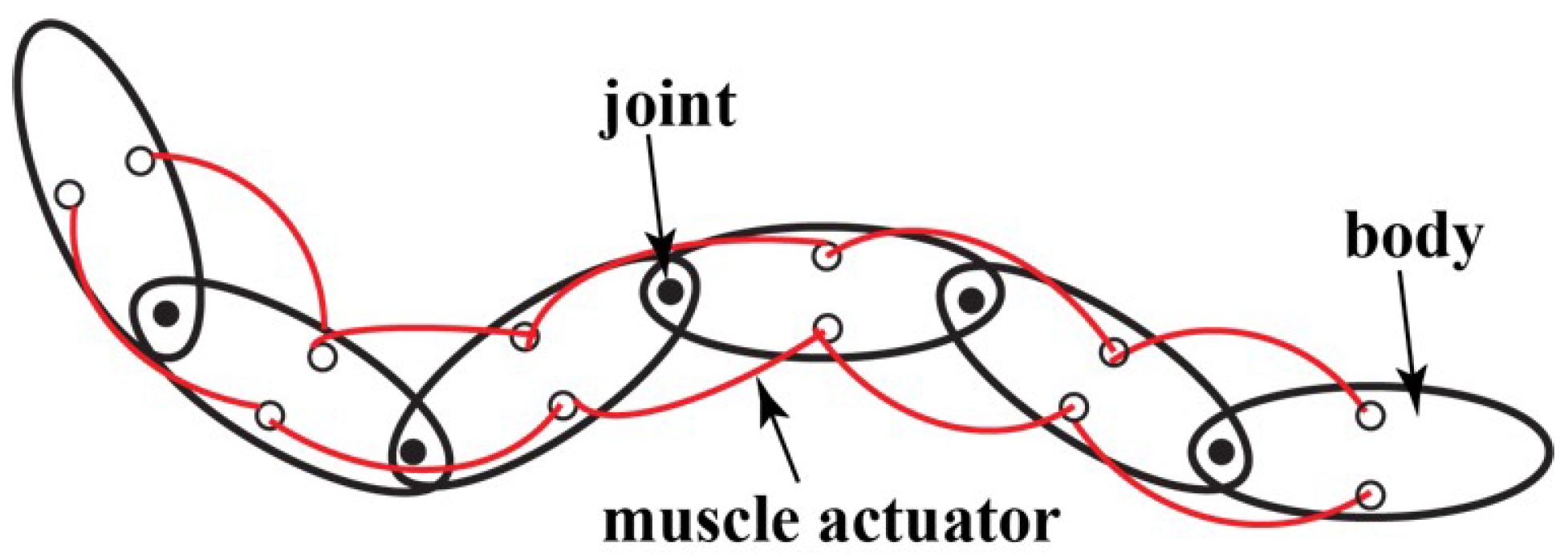
:1. Introduction
2. Kinematics
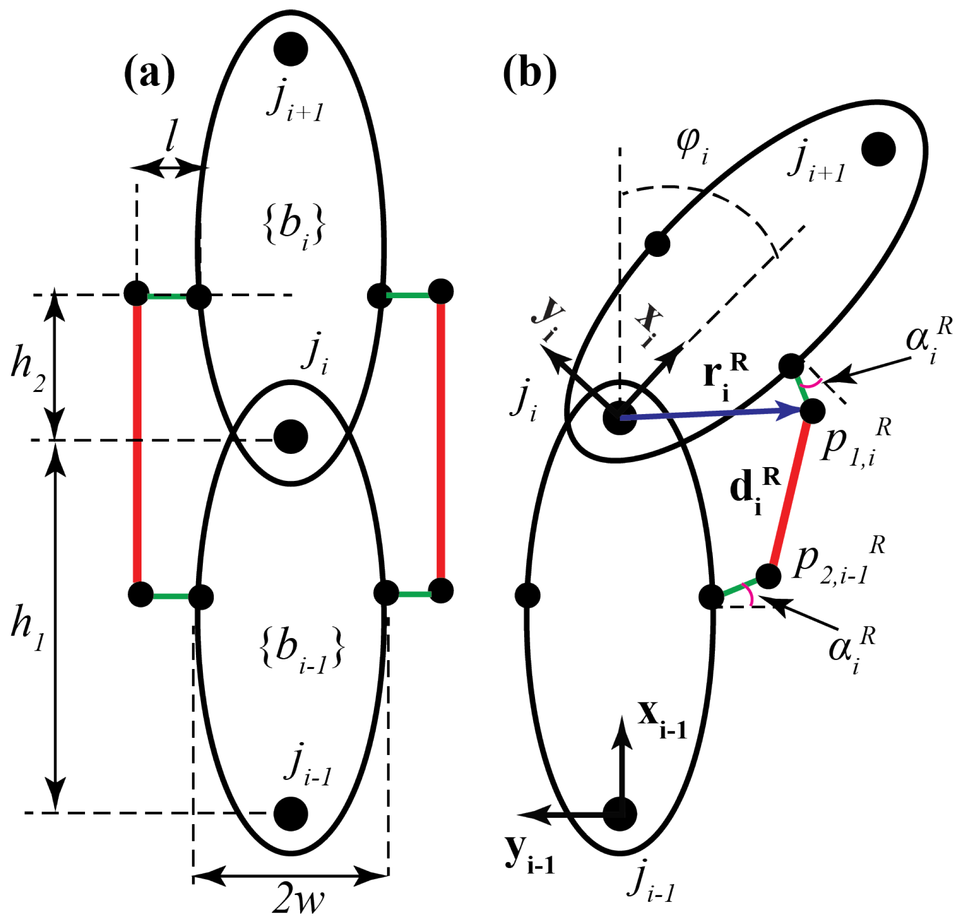
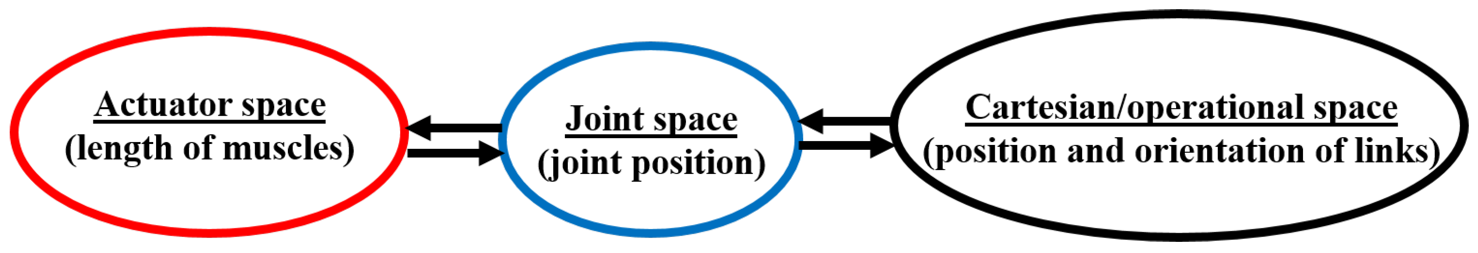
2.1. Actuator Space to Joint Space
- = length of each link;
- = distance from the joint to the attachment point;
- w = half width of each link;
- l = distance from w to muscle attachment point;
- = joint angle;
- = attachment point angle.
2.2. Joint Space to Cartesian Space
3. Dynamics
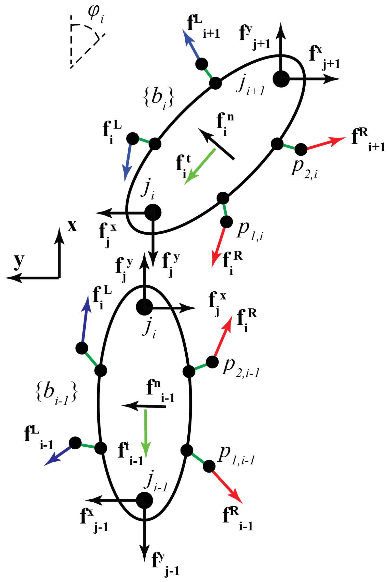
3.1. Dynamics of a Single Muscle-Driven Module
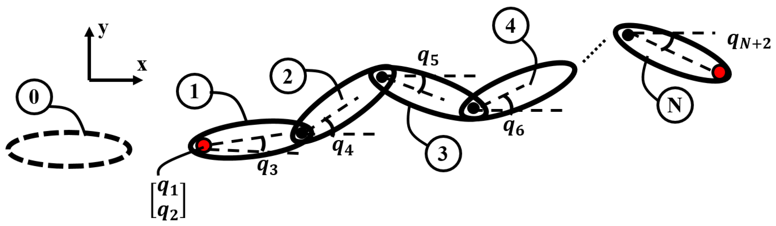
3.2. Dynamics of N-Link Muscle-Driven Snake Robot
4. Design and Prototyping
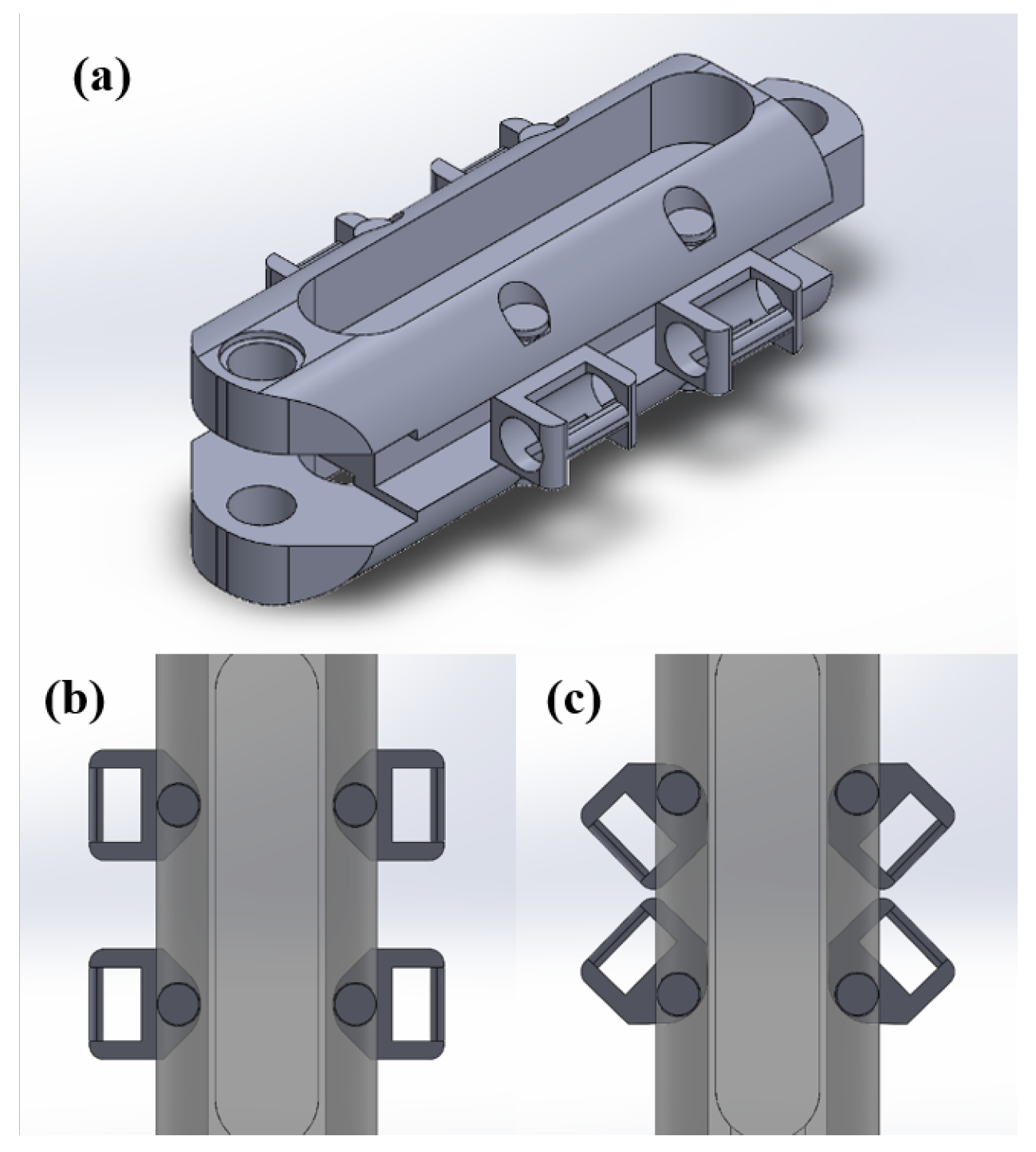
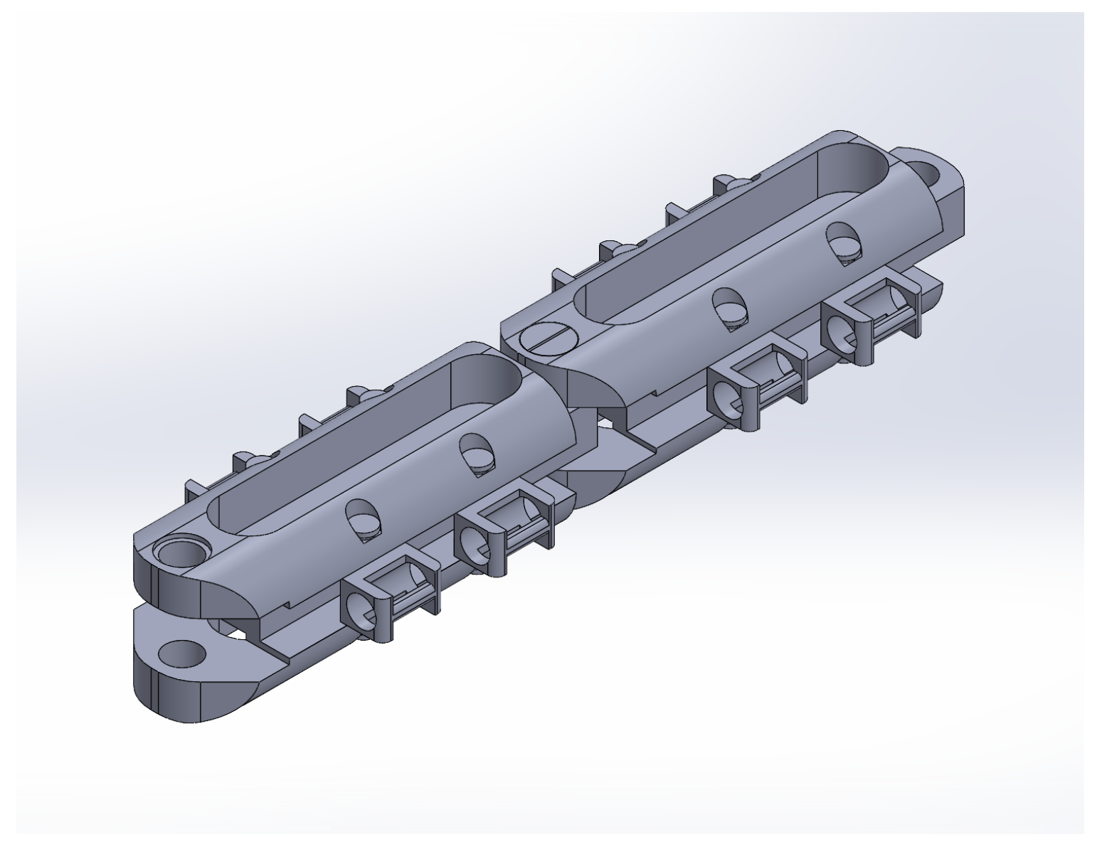
4.1. Conceptual Design and CAD Models
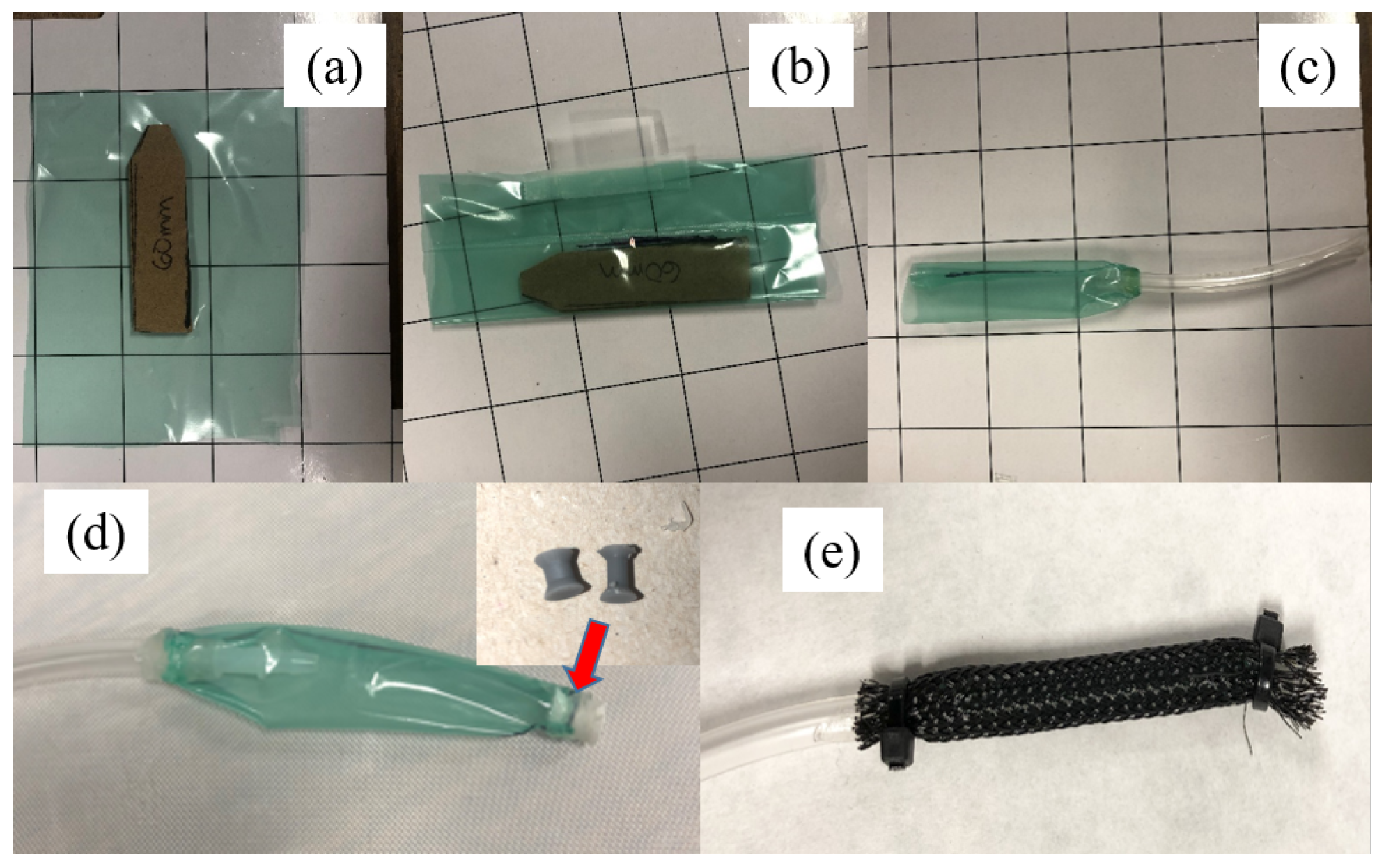
4.2. Prototyping
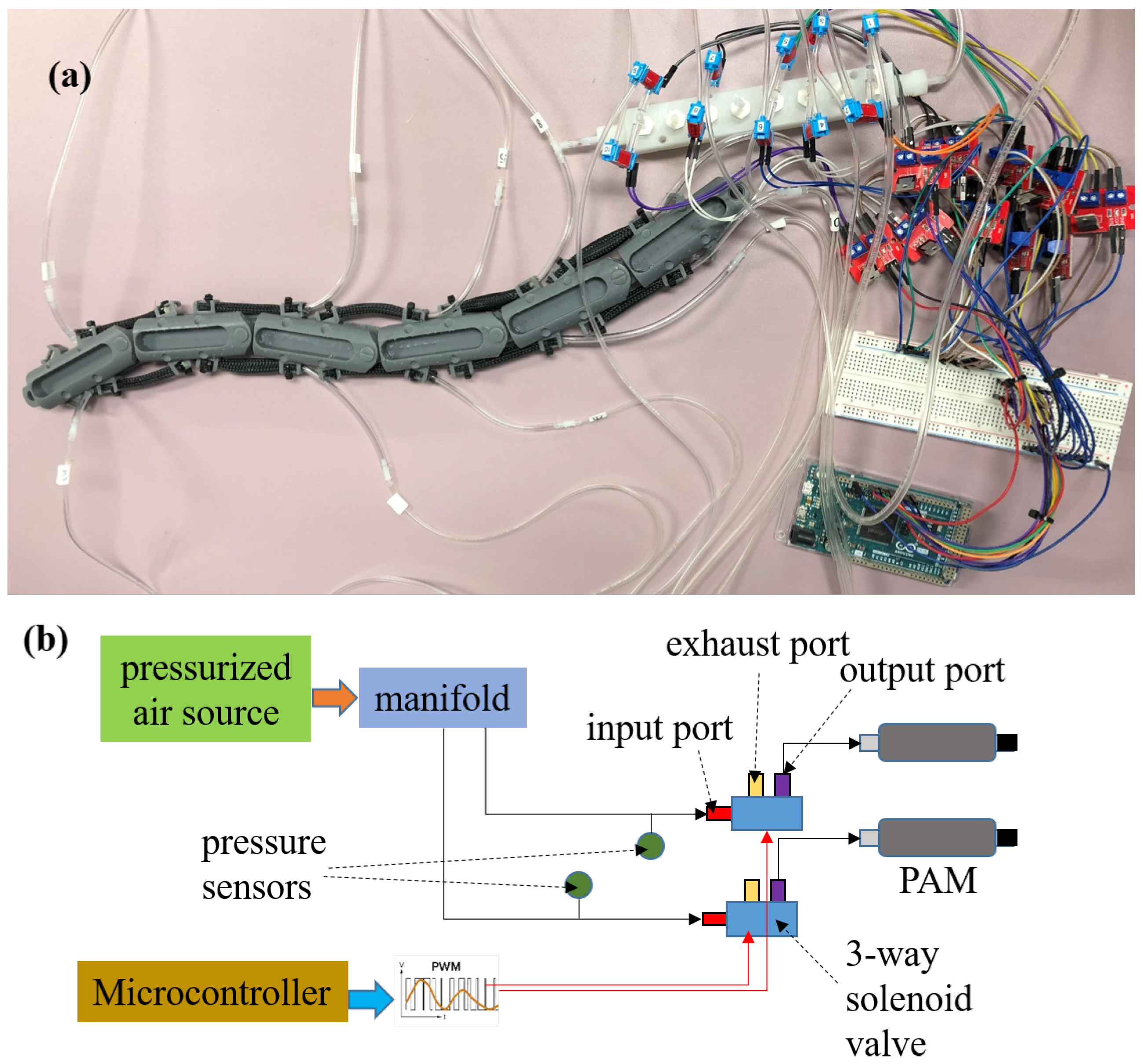
4.3. Control System: Pneumatics and Electronics
5. Testing and Characterization
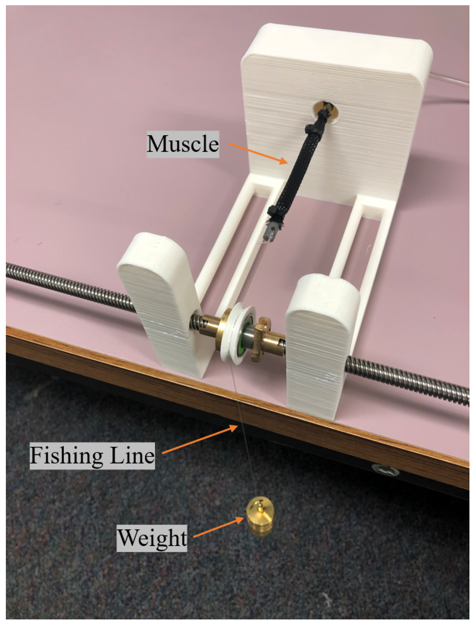
5.1. Kinematic Testing
5.2. Dynamic Testing
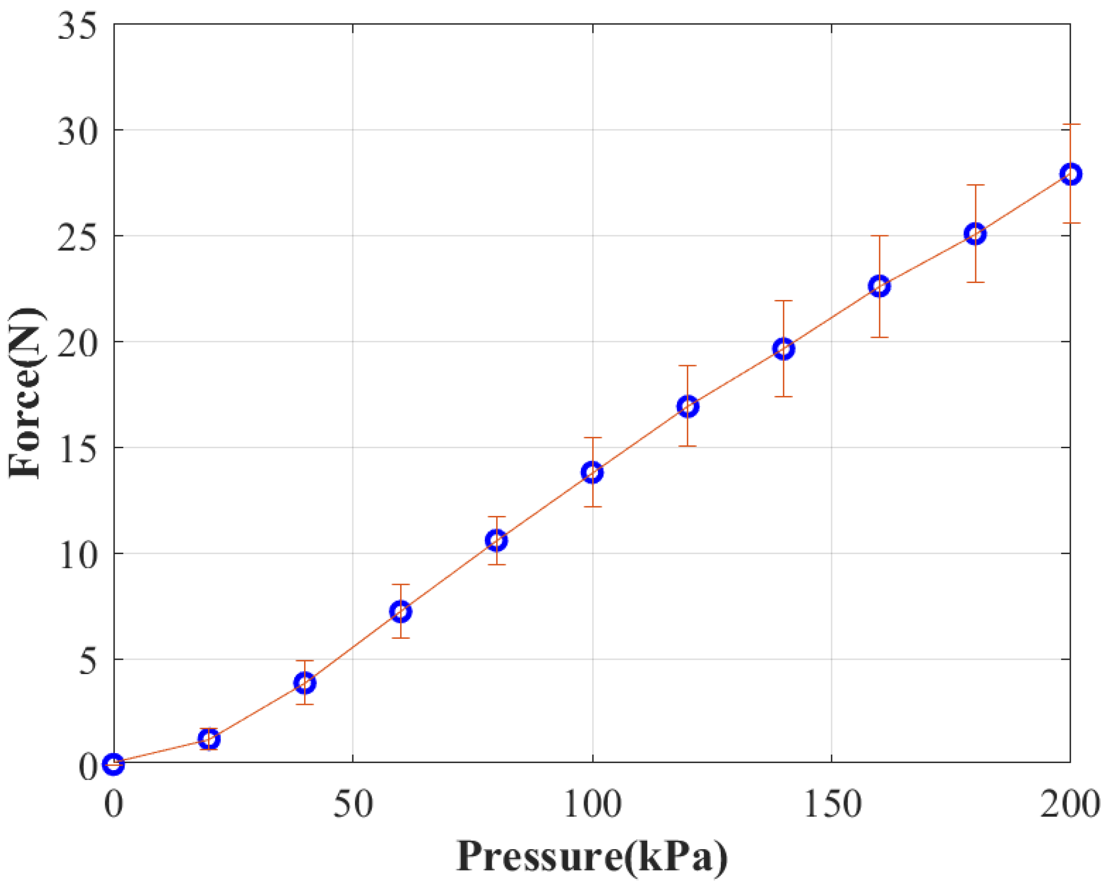
5.2.1. Isometric Contraction
5.2.2. Isotonic (Concentric) Contraction
6. Results and Discussion
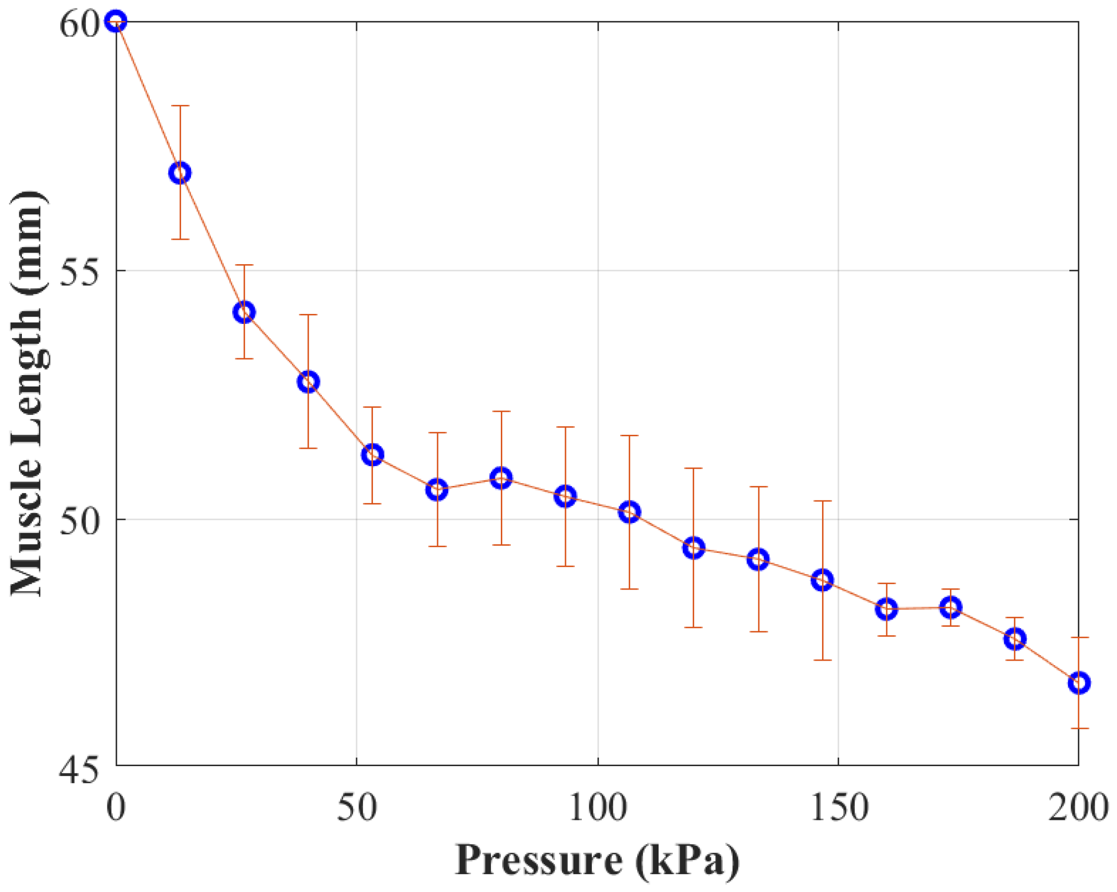
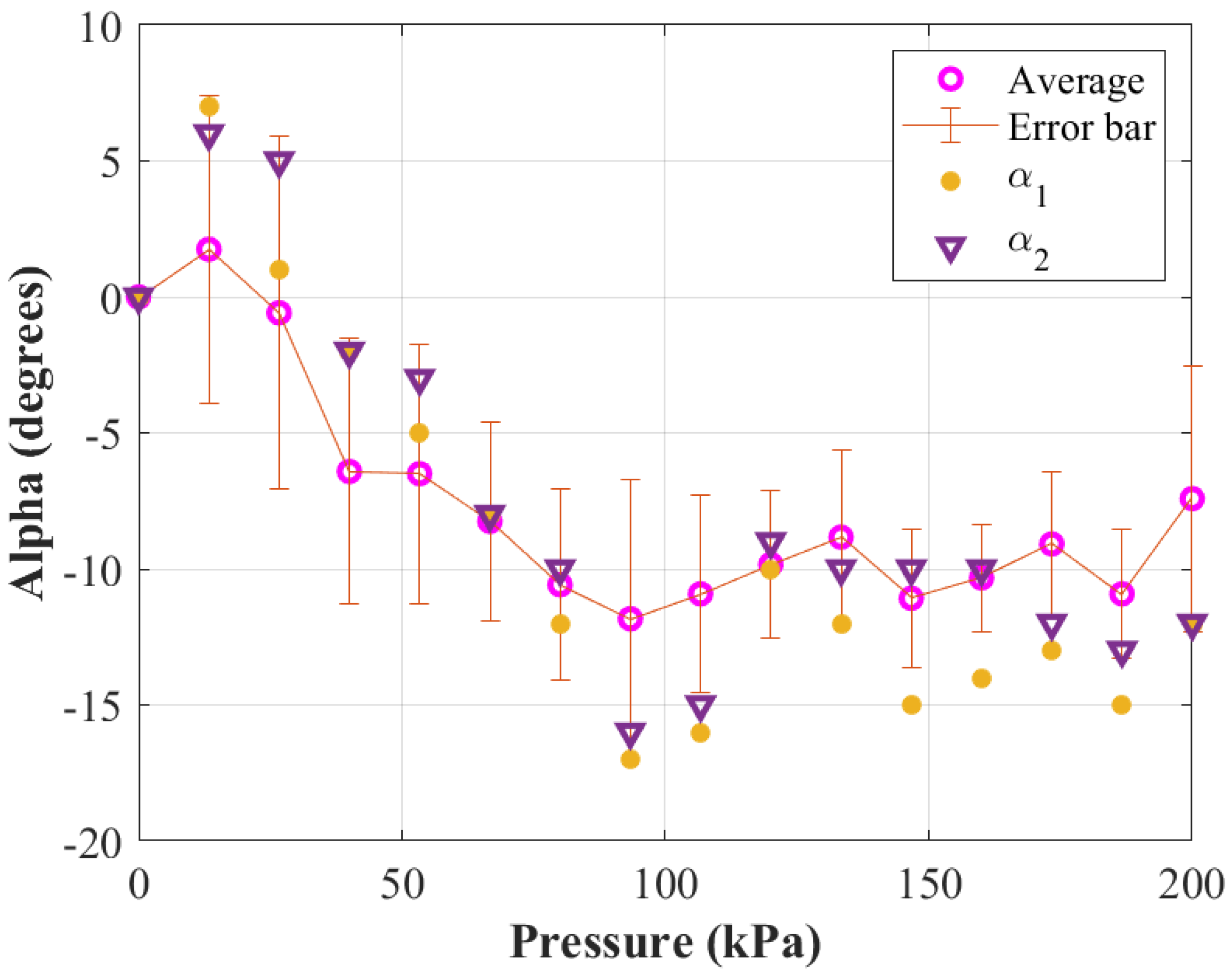
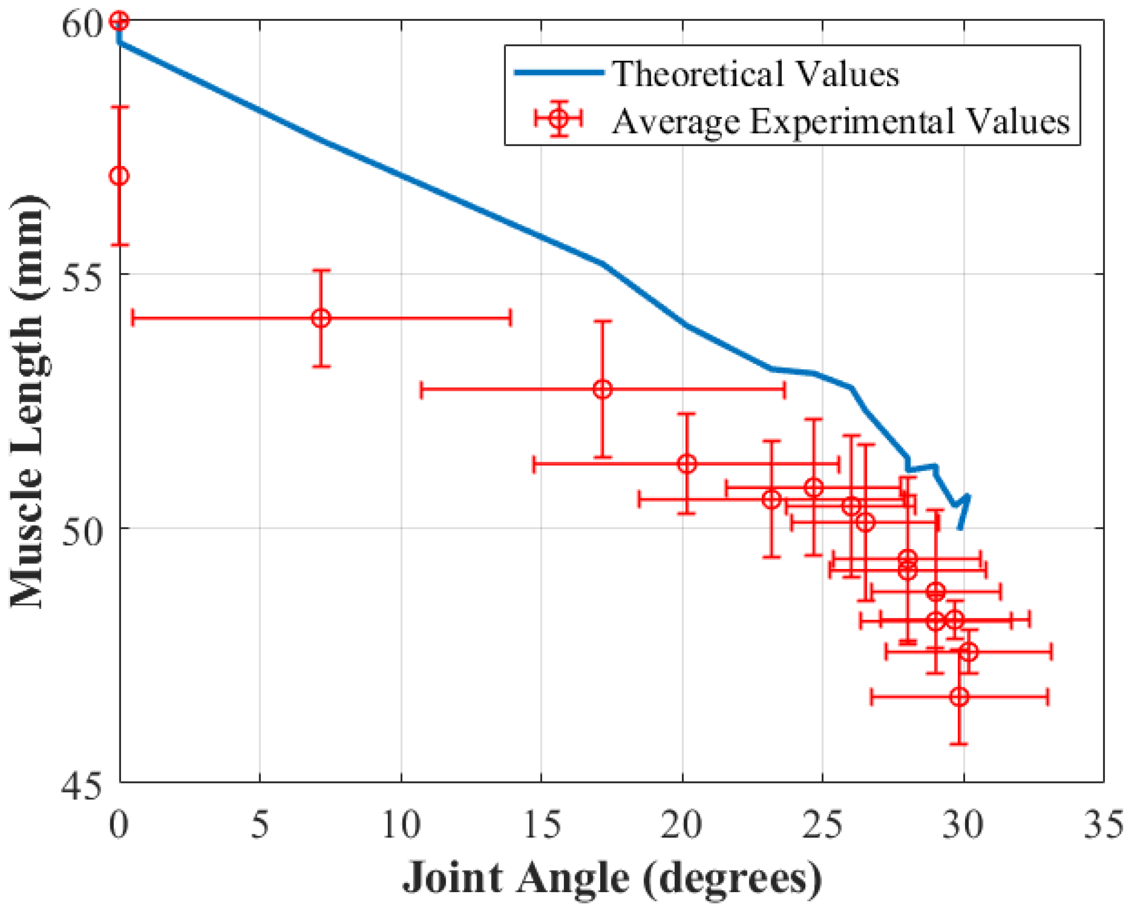
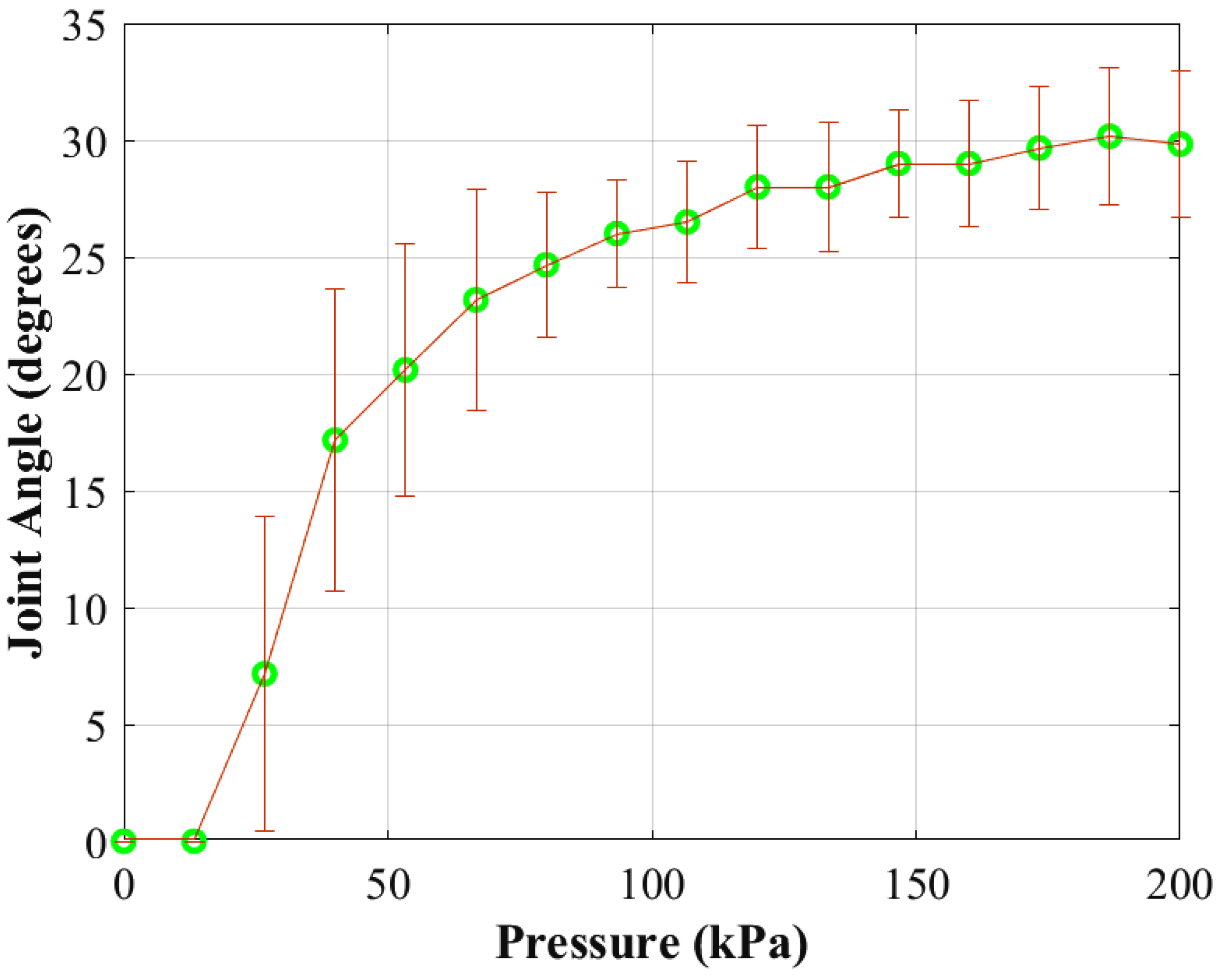
6.1. Kinematic Characterization
6.2. Dynamic Characterization
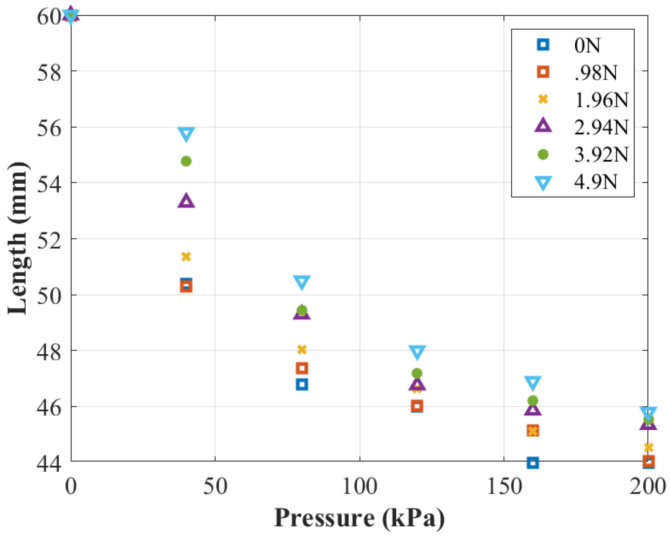
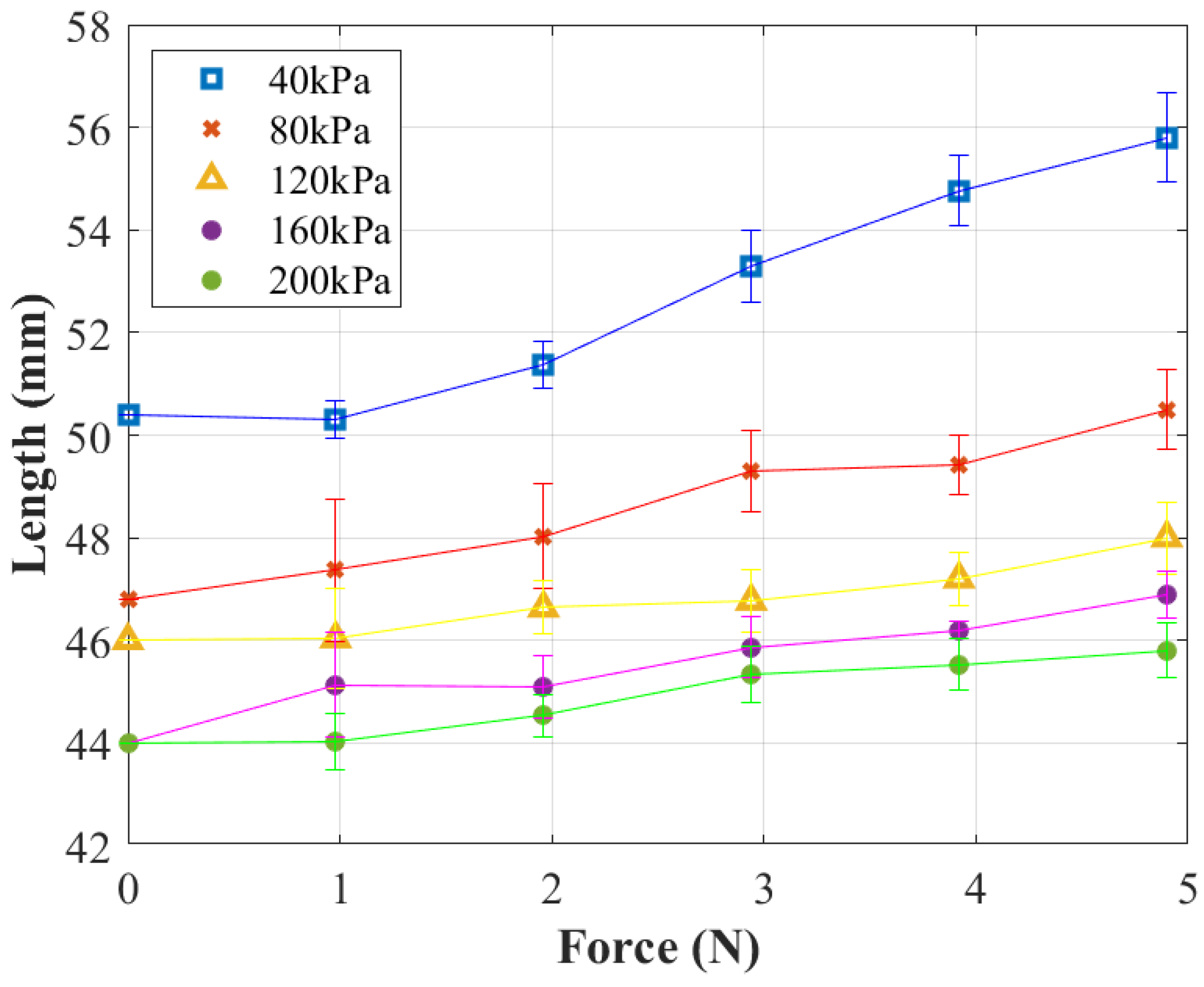
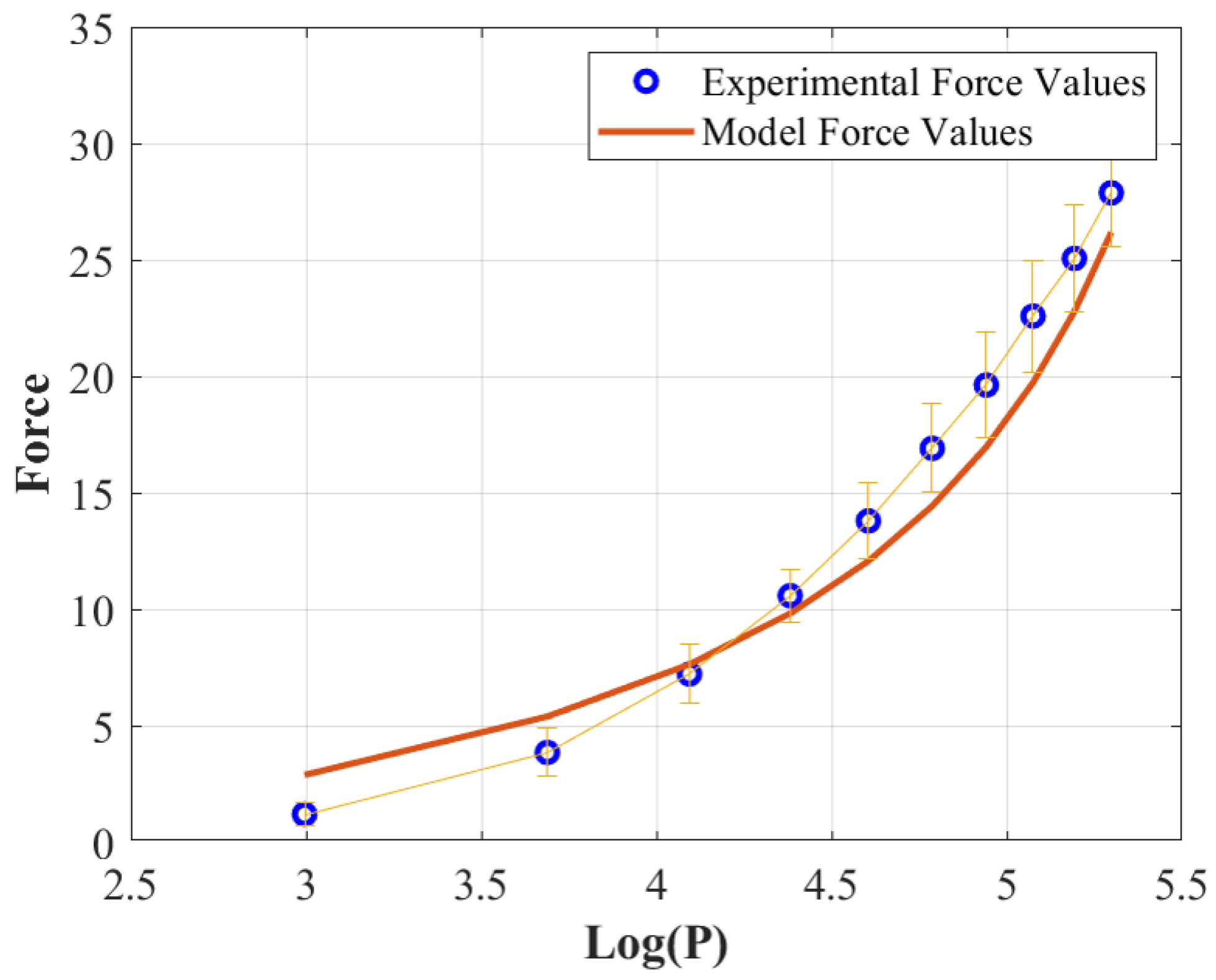
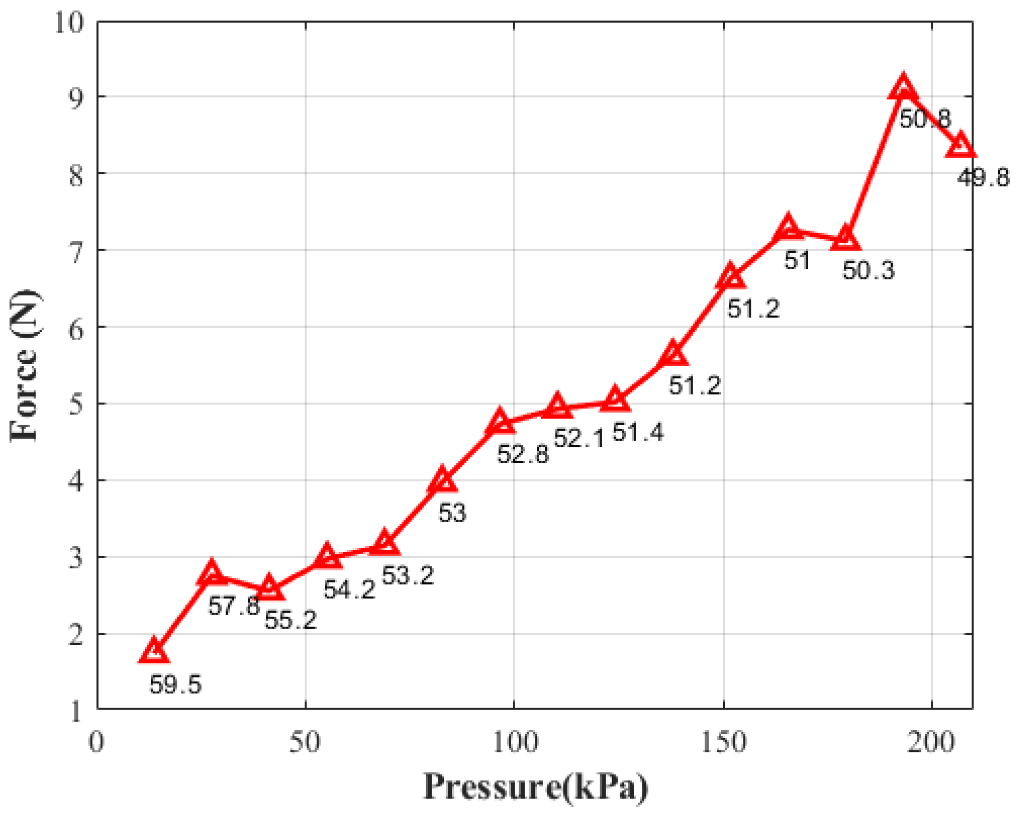
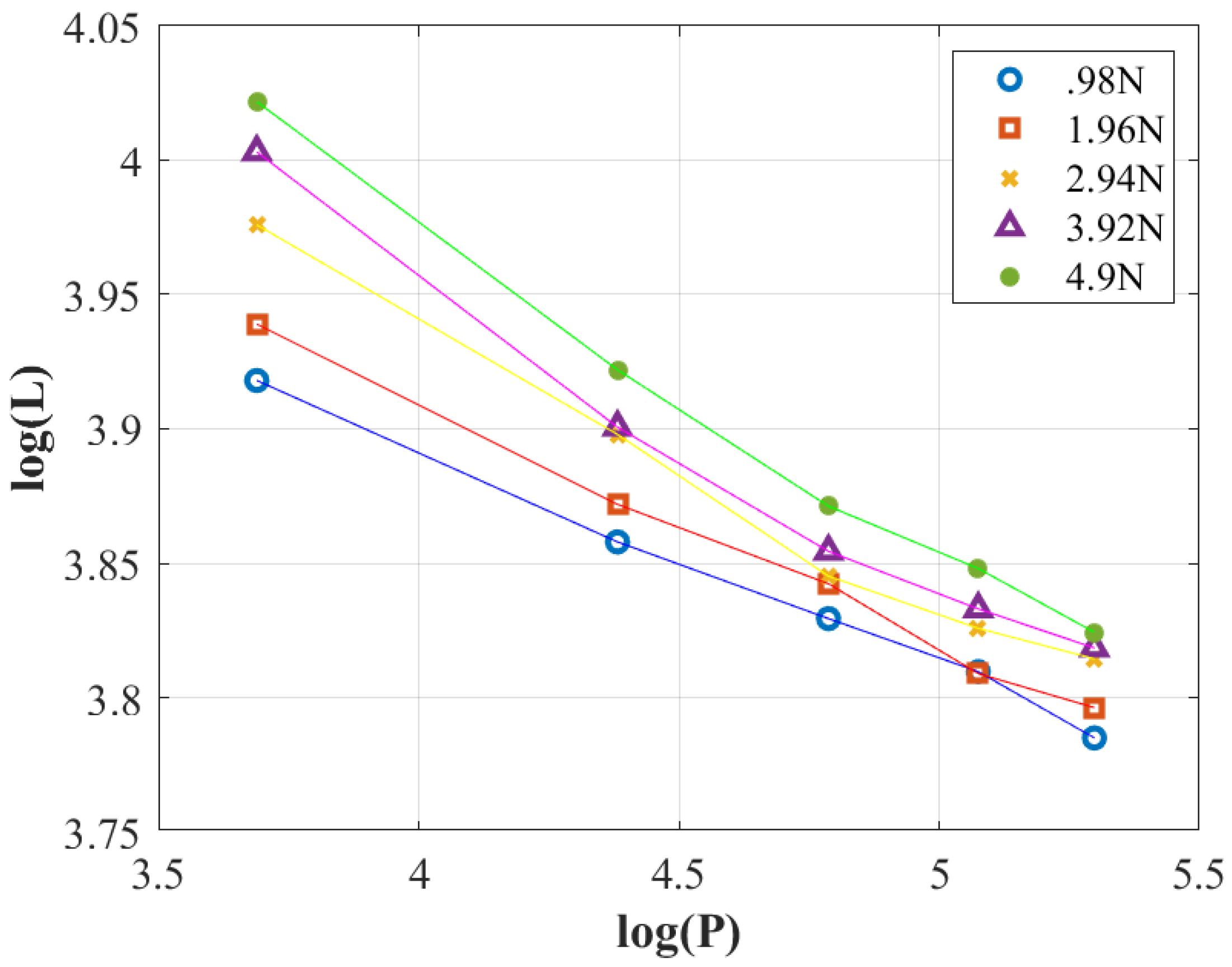
6.2.1. Force–Pressure–Length Model
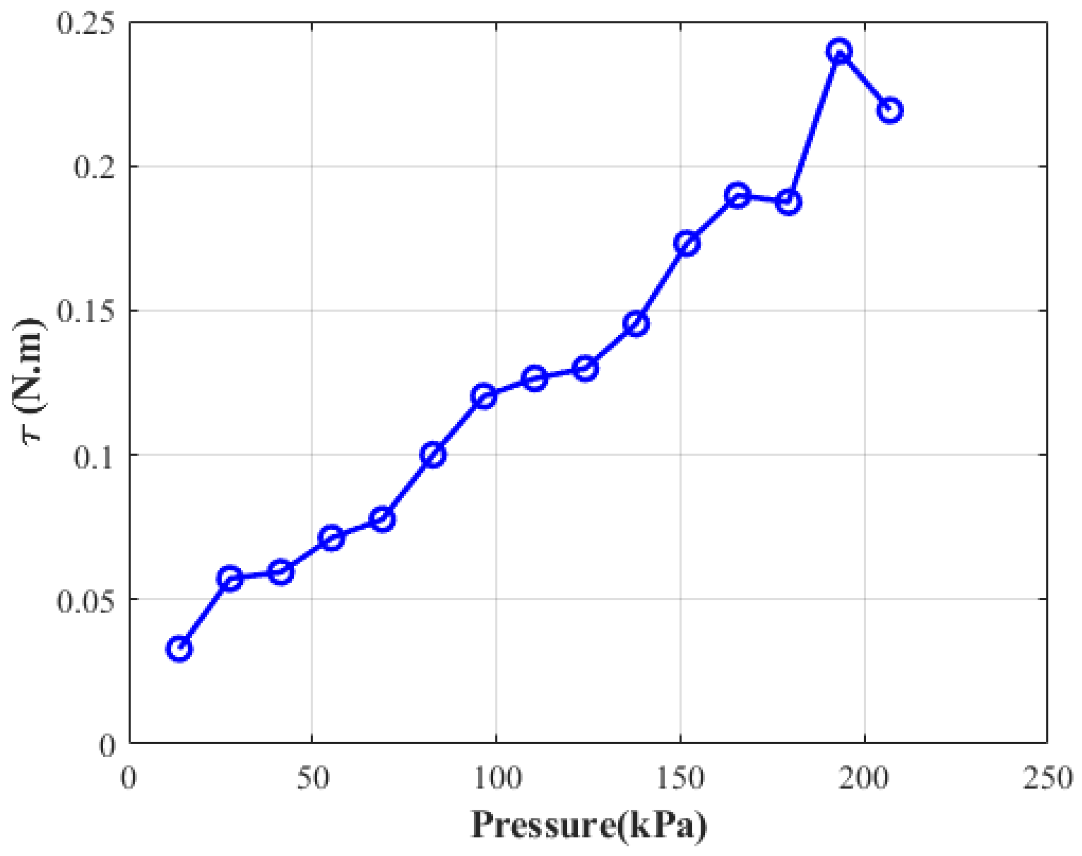
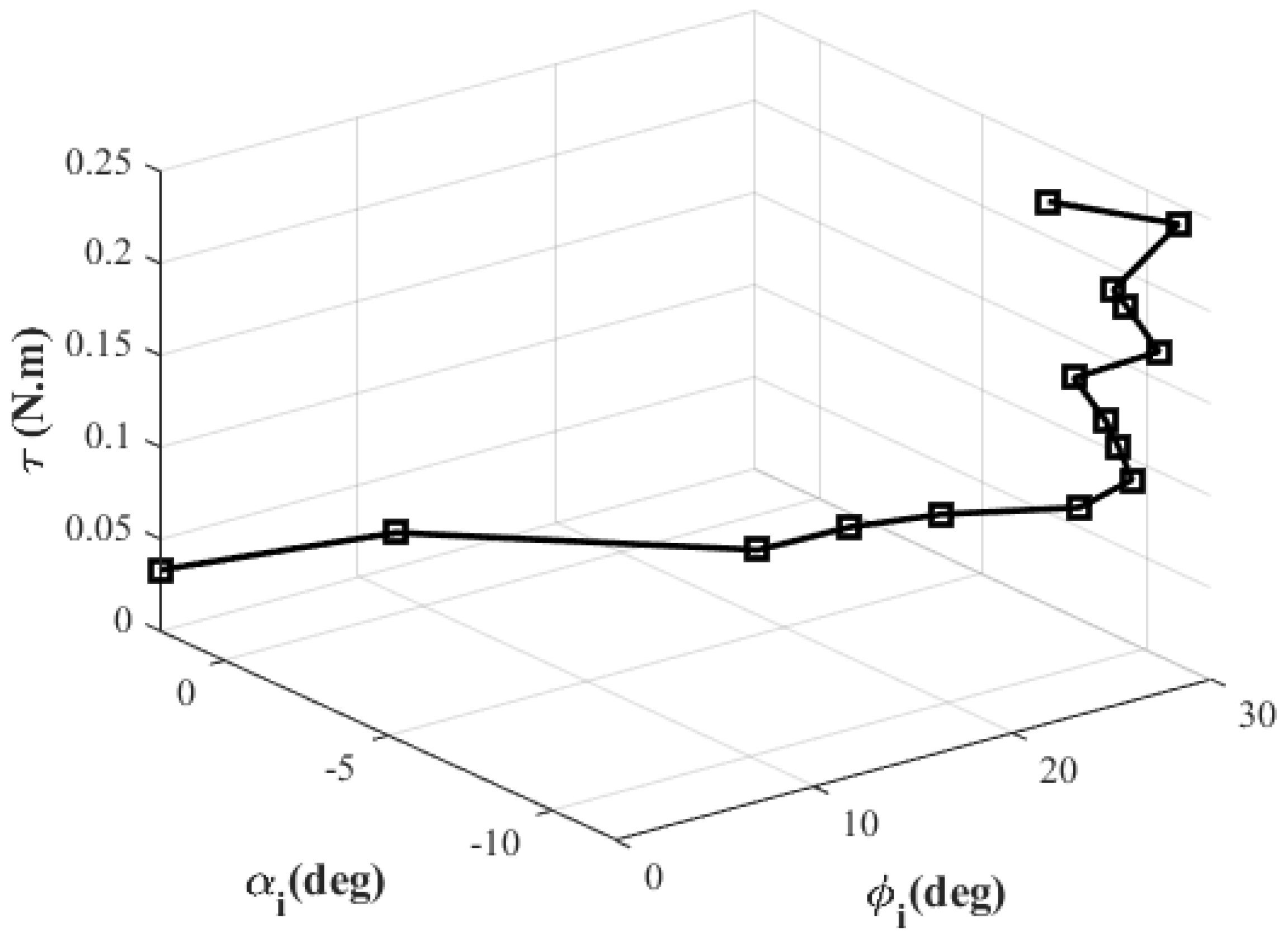
6.2.2. Dynamic Model-Based Torque Characterization
6.2.3. Power Consumption Efficiency Analysis
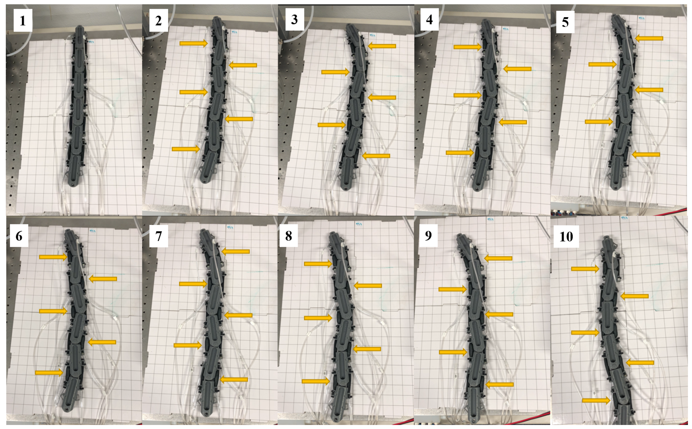
6.3. A Muscle-Driven Six-Link Snake Robot Locomotion
7. Conclusions
Author Contributions
Funding
Institutional Review Board Statement
Informed Consent Statement
Data Availability Statement
Conflicts of Interest
Abbreviations
| PAM | Pneumatic Artificial Muscle |
| ACM III | Active Cord Mechanism III |
| PEA | Parallel Elastic Actuator |
| 6D | 6-dimensional |
| TPE | Thermoplastic Elastomer |
| SLA | Stereolithography |
| CAD | Computer Aided Design |
Nomenclature
| a 3D position vector of point on link (body) expressed in the body frame | |
| a 3D position vector of point on link (body) expressed in the body frame | |
| a 3D position vector from joint to expressed in the body frame | |
| transpose of a given vector | |
| a vector describing a quantity on the right-side of a given link (body) | |
| a vector describing a quantity on the left-side of a given link (body) | |
| a vector describing a quantity at a given joint | |
| a vector describing a quantity at a given body | |
| a 6D spatial vector describing a quantity at a given body | |
| x, y, and z components of a given 3D vector | |
| a Homogeneous transformation matrix mapping the body frame to | |
| a rotation matrix describing orientation of the body frame w.r.t | |
| a general coordinate transformation matrix (a spatial matrix) from the body frame to | |
| transpose of a given matrix |
References
- Koopaee, M.J. Design, modelling and control of a modular snake robot with torque feedback for pedal wave locomotion on surfaces with irregularities. Ph.D. Thesis, University of Canterbury, Christchurch, New Zealand, 2019. [Google Scholar]
- Pettersen, K.Y. Snake robots. Annu. Rev. Control 2017, 44, 19–44. [Google Scholar] [CrossRef]
- Hirose, S. Biologically Inspired Robots; Oxford Science Publications: Oxford, UK, 1993. [Google Scholar]
- Rezapour, E.; Pettersen, K.Y.; Liljebäck, P.; Gravdahl, J.T.; Kelasidi, E. Path following control of planar snake robots using virtual holonomic constraints: Theory and experiments. Robot. Biomim. 2014, 1, 3. [Google Scholar] [CrossRef] [PubMed] [Green Version]
- Liljeback, P.; Pettersen, K.Y.; Stavdahl, Ø.; Gravdahl, J.T. Experimental Investigation of Obstacle-Aided Locomotion with a Snake Robot. IEEE Trans. Robot. 2011, 27, 792–800. [Google Scholar] [CrossRef] [Green Version]
- Rollinson, D.; Bilgen, Y.; Brown, B.; Enner, F.; Ford, S.; Layton, C.; Rembisz, J.; Schwerin, M.; Willig, A.; Velagapudi, P.; et al. Design and architecture of a series elastic snake robot. In Proceedings of the 2014 IEEE/RSJ International Conference on Intelligent Robots and Systems, Chicago, IL, USA, 14–18 September 2014; pp. 4630–4636. [Google Scholar] [CrossRef]
- Borenstein, J.; Hansen, M.; Borrell, A. The OmniTread OT4 serpentine robot—design and performance. J. Field Robot. 2007, 24, 601–621. [Google Scholar] [CrossRef] [Green Version]
- Onal, C.D.; Rus, D. Autonomous undulatory serpentine locomotion utilizing body dynamics of a fluidic soft robot. Bioinspir. Biomim. 2013, 8, 026003. [Google Scholar] [CrossRef]
- Luo, M.; Agheli, M.; Onal, C.D. Theoretical modeling and experimental analysis of a pressure-operated soft robotic snake. Soft Robot. 2014, 1, 136–146. [Google Scholar] [CrossRef]
- Luo, M.; Pan, Y.; Skorina, E.H.; Tao, W.; Chen, F.; Ozel, S.; Onal, C.D. Slithering towards autonomy: A self-contained soft robotic snake platform with integrated curvature sensing. Bioinspir. Biomim. 2015, 10, 055001. [Google Scholar] [CrossRef]
- Branyan, C.; Fleming, C.; Remaley, J.; Kothari, A.; Tumer, K.; Hatton, R.L.; Mengüç, Y. Soft snake robots: Mechanical design and geometric gait implementation. In Proceedings of the 2017 IEEE International Conference on Robotics and Biomimetics (ROBIO), Macau SAR, China, 5–8 December 2017; pp. 282–289. [Google Scholar] [CrossRef]
- Branyan, C.; Menğüç, Y. Soft Snake Robots: Investigating the Effects of Gait Parameters on Locomotion in Complex Terrains. In Proceedings of the 2018 IEEE/RSJ International Conference on Intelligent Robots and Systems (IROS), Madrid, Spain, 1–5 October 2018; pp. 1–9. [Google Scholar]
- Luo, M.; Wan, Z.; Sun, Y.; Skorina, E.H.; Tao, W.; Chen, F.; Gopalka, L.; Yang, H.; Onal, C.D. Motion Planning and Iterative Learning Control of a Modular Soft Robotic Snake. Front. Robot. AI 2020, 7, 599242. [Google Scholar] [CrossRef] [PubMed]
- Godage, I.S. Swimming Locomotion of Soft Robotic Snakes. arXiv 2019, arXiv:1908.05250. [Google Scholar]
- Davis, S.; Tsagarakis, N.; Canderle, J.; Caldwell, D.G. Enhanced modelling and performance in braided pneumatic muscle actuators. Int. J. Robot. Res. 2003, 22, 213–227. [Google Scholar] [CrossRef]
- Zhang, J.; Sheng, J.; O’Neill, C.T.; Walsh, C.J.; Wood, R.J.; Ryu, J.H.; Desai, J.P.; Yip, M.C. Robotic Artificial Muscles: Current Progress and Future Perspectives. IEEE Trans. Robot. 2019, 35, 761–781. [Google Scholar] [CrossRef]
- Schroder, J.; Erol, D.; Kawamura, K.; Dillman, R. Dynamic pneumatic actuator model for a model-based torque controller. In Proceedings of the 2003 IEEE International Symposium on Computational Intelligence in Robotics and Automation, Computational Intelligence in Robotics and Automation for the New Millennium (Cat. No. 03EX694), Kobe, Japan, 16–20 July 2003; Volume 1, pp. 342–347. [Google Scholar]
- József, S.; Gábor, S.; János, G. Investigation and application of pneumatic artificial muscles. Biomech. Hung. 2010, 3, 208–214. [Google Scholar]
- Tondu, B.; Lopez, P. Modeling and control of McKibben artificial muscle robot actuators. IEEE Control Syst. Mag. 2000, 20, 15–38. [Google Scholar]
- Kothera, C.S.; Jangid, M.; Sirohi, J.; Wereley, N.M. Experimental characterization and static modeling of McKibben actuators. In Proceedings of the ASME International Mechanical Engineering Congress and Exposition, Chicago, IL, USA, 5–10 November 2006; Volume 47659, pp. 357–367. [Google Scholar]
- Arcus, A.G. Modeling of a Dynamic McKibben Style Muscle System Using Material Properties. Master’s Thesis, Rochester Institute of Technology, Rochester, NY, USA, 2018. [Google Scholar]
- Villegas, D.; Van Damme, M.; Vanderborght, B.; Beyl, P.; Lefeber, D. Third-generation pleated pneumatic artificial muscles for robotic applications: Development and comparison with mckibben muscle. Adv. Robot. 2012, 26, 1205–1227. [Google Scholar] [CrossRef]
- Balasubramanian, S.; Wei, R.; Perez, M.; Shepard, B.; Koeneman, E.; Koeneman, J.; He, J. RUPERT: An exoskeleton robot for assisting rehabilitation of arm functions. In Proceedings of the 2008 Virtual Rehabilitation, Vancouver, BC, Canada, 25–27 August 2008; pp. 163–167. [Google Scholar]
- Kobayashi, H.; Hiramatsu, K. Development of muscle suit for upper limb. In Proceedings of the 2004 IEEE International Conference on Robotics and Automation, ICRA’04, New Orleans, LA, USA, 26 April–1 May 2004; Volume 3, pp. 2480–2485. [Google Scholar]
- Koeneman, E.; Schultz, R.; Wolf, S.; Herring, D.; Koeneman, J. A pneumatic muscle hand therapy device. In Proceedings of the 26th Annual International Conference of the IEEE Engineering in Medicine and Biology Society, San Francisco, CA, USA, 1–5 September 2004; Volume 1, pp. 2711–2713. [Google Scholar]
- Wongsiri, S.; Laksanacharoen, S. Design and Construction of an Artificial Limb Driven by Artificial Muscles for Amputees. Available online: http://biobot.kmutnb.ac.th/publications/psu_uns_final1.pdf (accessed on 18 November 2021).
- Wehner, M.; Tolley, M.T.; Mengüç, Y.; Park, Y.L.; Mozeika, A.; Ding, Y.; Onal, C.; Shepherd, R.F.; Whitesides, G.M.; Wood, R.J. Pneumatic Energy Sources for Autonomous and Wearable Soft Robotics. Soft Robot. 2014, 1, 263–274. [Google Scholar] [CrossRef] [Green Version]
- Granosik, G.; Borenstein, J. Integrated joint actuator for serpentine robots. IEEE/ASME Trans. Mechatron. 2005, 10, 473–481. [Google Scholar] [CrossRef]
- Rezaei, S.M.; Barazandeh, F.; Haidarzadeh, M.S.; Sadat, S.M. The effect of snake muscular system on actuators’ torque. J. Intell. Robot. Syst. 2010, 59, 299–318. [Google Scholar] [CrossRef]
- Wang, T.; Wang, Z.; Wu, G.; Lei, L.; Zhao, B.; Zhang, P.; Shang, P. Design and analysis of a snake-like surgical robot with continuum joints. In Proceedings of the 2020 5th International Conference on Advanced Robotics and Mechatronics (ICARM), Shenzhen, China, 18–21 December 2020; pp. 178–183. [Google Scholar]
- Kakogawa, A.; Jeon, S.; Ma, S. Stiffness design of a resonance-based planar snake robot with parallel elastic actuators. IEEE Robot. Autom. Lett. 2018, 3, 1284–1291. [Google Scholar] [CrossRef]
- Ute, J.; Ono, K. Fast and efficient locomotion of a snake robot based on self-excitation principle. In Proceedings of the 7th International Workshop on Advanced Motion Control. Proceedings (Cat. No. 02TH8623), Maribor, Slovenia, 3–5 July 2002; pp. 532–539. [Google Scholar]
- Gray, J. The mechanism of locomotion in snakes. J. Exp. Biol. 1946, 23, 101–120. [Google Scholar] [CrossRef]
- Ma, S. Analysis of snake movement forms for realization of snake-like robots. In Proceedings of the 1999 IEEE International Conference on Robotics and Automation (Cat. No. 99CH36288C), Detroit, MI, USA, 10–15 May 1999; Volume 4, pp. 3007–3013. [Google Scholar]
- Jayne, B.C. Muscular mechanisms of snake locomotion: An electromyographic study of the sidewinding and concertina modes of Crotalus cerastes, Nerodia fasciata and Elaphe obsoleta. J. Exp. Biol. 1988, 140, 1–33. [Google Scholar] [CrossRef] [PubMed]
- Jayne, B.C. Muscular mechanisms of snake locomotion: An electromyographic study of lateral undulation of the Florida banded water snake (Nerodia fasciata) and the yellow rat snake (Elaphe obsoleta). J. Morphol. 1988, 197, 159–181. [Google Scholar] [CrossRef] [PubMed]
- Moon, B.R.; Gans, C. Kinematics, muscular activity and propulsion in gopher snakes. J. Exp. Biol. 1998, 201, 2669–2684. [Google Scholar] [CrossRef]
- Guo, Z.; Mahadevan, L. Limbless undulatory propulsion on land. Proc. Natl. Acad. Sci. USA 2008, 105, 3179–3184. [Google Scholar] [CrossRef] [Green Version]
- Geijtenbeek, T.; van de Panne, M.; van der Stappen, A.F. Flexible Muscle-Based Locomotion for Bipedal Creatures. ACM Trans. Graph. 2013, 32, 206. [Google Scholar] [CrossRef]
- Wang, J.M.; Hamner, S.R.; Delp, S.L.; Koltun, V. Optimizing Locomotion Controllers Using Biologically-Based Actuators and Objectives. ACM Trans. Graph. 2012, 31, 25. [Google Scholar] [CrossRef] [PubMed]
- Cruz Ruiz, A.; Pontonnier, C.; Pronost, N.; Dumont, G. Muscle-Based Control for Character Animation. Comput. Graph. Forum 2017, 36, 122–147. [Google Scholar] [CrossRef] [Green Version]
- Featherstone, R. Rigid Body Dynamics Algorithms; Springer: New York, NY, USA, 2014. [Google Scholar]
- Holland, D.P.; Park, E.J.; Polygerinos, P.; Bennett, G.J.; Walsh, C.J. The soft robotics toolkit: Shared resources for research and design. Soft Robot. 2014, 1, 224–230. [Google Scholar] [CrossRef]


Publisher’s Note: MDPI stays neutral with regard to jurisdictional claims in published maps and institutional affiliations. |
© 2021 by the authors. Licensee MDPI, Basel, Switzerland. This article is an open access article distributed under the terms and conditions of the Creative Commons Attribution (CC BY) license (https://creativecommons.org/licenses/by/4.0/).
Share and Cite
Lopez, M.; Haghshenas-Jaryani, M. A Muscle-Driven Mechanism for Locomotion of Snake-Robots. Automation 2022, 3, 1-26. https://doi.org/10.3390/automation3010001
Lopez M, Haghshenas-Jaryani M. A Muscle-Driven Mechanism for Locomotion of Snake-Robots. Automation. 2022; 3(1):1-26. https://doi.org/10.3390/automation3010001
Chicago/Turabian StyleLopez, Marcela, and Mahdi Haghshenas-Jaryani. 2022. "A Muscle-Driven Mechanism for Locomotion of Snake-Robots" Automation 3, no. 1: 1-26. https://doi.org/10.3390/automation3010001
APA StyleLopez, M., & Haghshenas-Jaryani, M. (2022). A Muscle-Driven Mechanism for Locomotion of Snake-Robots. Automation, 3(1), 1-26. https://doi.org/10.3390/automation3010001