Article

Specific Absorption Rate Analysis of Wideband Multiple-Input Multiple-Output Antennas for Upper Mid-Band LTE 46/47 and n102 Future Generation Applications

by
Muhammad Zahid
* and
Yasar Amin
Department of Telecommunication Engineering, University of Engineering and Technology, Taxila 47050, Pakistan
*
Author to whom correspondence should be addressed.
Telecom 2025, 6(2), 22; https://doi.org/10.3390/telecom6020022
Submission received: 2 January 2025 / Revised: 18 March 2025 / Accepted: 27 March 2025 / Published: 31 March 2025

Abstract

:
The design of wideband multi-port multiple-input multiple-output (MIMO) antennas and their optimization are very important for next-generation smartphones with the increase in massive connectivity. This paper offers the design, simulation, measurement, and specific absorption rate (SAR) analysis of a Pi-shaped ten-element MIMO antenna system for use in the upper mid-band, covering LTE 46 (5.15–5.925 GHz), LTE 47 (5.855–5.925 GHz), and n102 (5.925–6.425 GHz), thus meeting a good fractional bandwidth of 32.7% with a maximum peak gain of 2.89 dBi. Hence, it is well suited for high-isolation (<−10 dB), compactness, and wideband (4.7–6.5 GHz) applications suitable for the current communication system needs. The overall size of the proposed system is 125 mm × 70 mm, with a planar dielectric material Rogers RT/5880. Designing the proposed antenna with multiple units entails the preservation of the spatial features of the antenna alongside the reduction of the mutual coupling for adjacent elements by using a decoupling structure. Due to the high accuracy of the positioning elements and precise geometric transformations, the antenna system provides high-performance analysis based on reflection coefficients, radiation patterns, and each antenna’s averaged efficiency values (76.12–91.57%).

1. Introduction

Future generation frequency for the upper mid-band has turned out to be a major building block of 5G due to its many benefits against mmWave technology. These include reversed coverage—especially in rural areas—lowered power consumption, better penetration, better data rates, and improved mobility [1,2]. For expanding the demand of high-data-rate communication system, multiple antenna techniques at both the transmitter and receiver have developed. A glance at some of these systems like multiple-input multiple-output (MIMO) shows that they increase the channel capacity of communication links without necessarily increasing the allocated power or bandwidth [3,4]. MIMO technologies are still one of the key elements of 5G wireless networks. Their performance is dependent on the multi-path characteristics of the communication channels and using carefully designed MIMO systems. On this front, low-profile wideband antennas are becoming popular due to their small size, light weight, lowered cost, and simpler fabrication. It additionally states that in the case of close placement of the antennas, there is great mutual coupling, which is undesirable from an efficiency aspect. For successful wireless communication in MIMO systems, a minimum isolation of 12 dB between antenna elements is required [5]. Several solutions have been put forward to tackle coupling and attain a high level of isolation. Some of these are parasitic elements [6], defected ground structures (DGSs) [7], stubs [8], self-isolating decoupling structures [9], and artificial intelligent techniques [10]. These methods are useful in the improvement of the performance of antennas, especially where the available space is very limited.
Advancement of the fifth generation (5G) network is focused mainly on attaining the right amount of so-called spectral efficiency, bandwidth, and channel capacity, with the C-band (4.0–8.0 GHz) being the important frequency band of international interest [11]. MIMO antenna technology plays a vital role in 5G smartphones, helping to achieve faster data speeds, better signal reliability, and more efficient use of the available spectrum. Since smartphones have limited space, engineers have developed innovative antenna designs like planar inverted-F antennas (PIFAs), slot antennas, monopole arrays, dielectric resonator antennas (DRAs), and metasurface-based antennas to optimize performance while keeping interference low [12]. To further enhance signal quality, techniques such as decoupling networks, electromagnetic bandgap (EBG) structures, and metamaterials are used to reduce unwanted interactions between antennas. Another key challenge is specific absorption rate (SAR) compliance, ensuring that radiation exposure remains within safe limits. Solutions like artificial magnetic conductors (AMCs) and metasurfaces help balance safety with high performance [13,14]. Thus, this band is an ideal solution for the economy and widespread distribution of coverage with 5G networks. In view of this, a large number of antennas is important in delivering high data rates [15]. But as wireless evolution advances to higher frequencies, this results in limitations such as short transmission ranges and more signal path loss. To counter these problems, solutions have been proposed such as the reconfigurable intelligent surface [16], which can actively manage the paths of signals within given systems. Further, the design requirements of wideband MIMO antennas for compact platforms such as smartphones face extra difficulties such as poor isolation between antennas and low space for integrating a number of antennas, which result in reduced spectral efficiency [17]. To avoid these challenges, the desirable antennas have a wider bandwidth, can operate in multiple bands, and have higher levels of separation between the elements. Nevertheless, the task of attaining improved spectral efficiency for 5G devices presents some real challenges. Wideband MIMO antennas with tuning possibilities across upper mid-frequency bands have been considered as one of the most suitable solutions [11].
The literature also discusses on several optimized MIMO antenna designs for 5G smartphones such as compact antennas using low proximity [18], compact size [19], and multi-band MIMO antenna using monopole [20,21], dipole [22], and patch antennas [23,24]. Nevertheless, these designs are subject to certain drawbacks, for instance, additional coaxial local conversion losses [17,23], the radiation characteristics of wideband MIMO antennas being compromised [17,25], and higher design gradients. For instance, Ref. [26] presented a ten-element dual-band MIMO antenna with a neutralizing line decoupling structure, but it has a low efficiency of only 45% and an isolation of only 12 dB. It is further known that the number of antenna ports must be raised in order to provide support to more users, increase channel capacity, and yield higher data rates [27]. Thus, extensive studies have been dedicated to design eight-element antennas for different 5G applications [1,28,29,30,31,32,33,34,35]. However, low antenna flexibility is a common issue with most current research works; therefore, there is a need for highly flexible eight-element antennas that are optimized for 5G mid-band frequencies.
The novelty and contributions of our paper are as follows:
  • We proposed a Pi-shaped ten-element MIMO antenna that consists of a decoupling structure that offers isolation of greater than −10 dB across the upper mid-band (LTE 46/47, n102), with a fractional bandwidth of 32.72%.
  • SAR analysis: The maximum and minimum SARs observed in hand simulation for 1 g of tissue were 0.118 W/kg and 0.0606 W/kg, and the maximum and minimum SARs observed in the presence of head simulation for 10 g of tissue were 18.7 W/kg and 1.72 W/kg.
  • The mutual coupling performance of the proposed ten-element antenna was examined, and the results show good values for the envelope correlation coefficient (ECC) < 0.03, which proves the appropriateness of the antenna for real-time diversity environments.
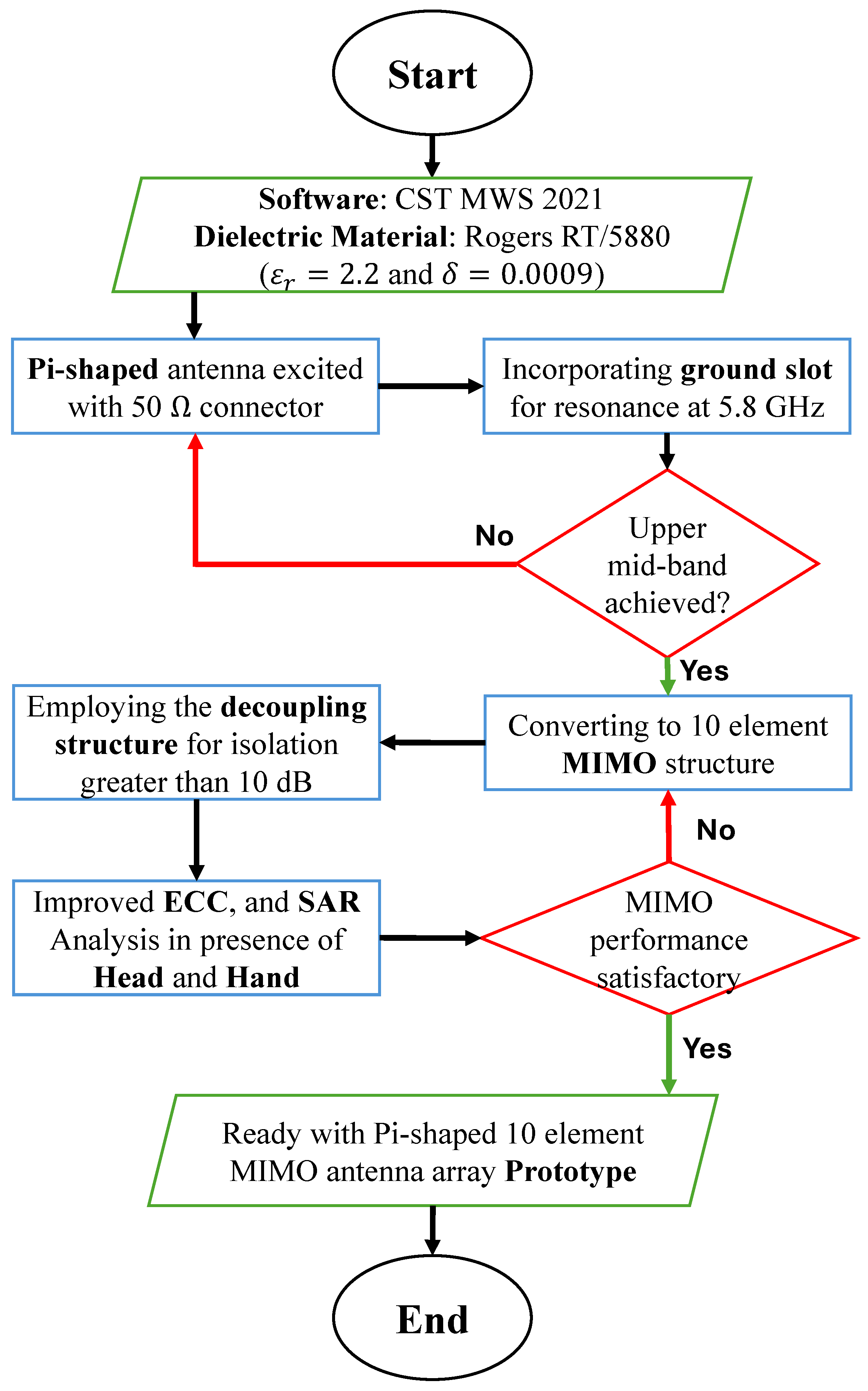
Therefore, using the method of independent frequency control, an extensive parametric study was carried out on different design parameters. Moreover, a Pi-shaped ten-element MIMO antenna array was designed and measured for the verification of the design concept presented in this work. The obtained experimental results show a high isolation of more than 12 dB, presenting the best level of high-data-rate broadband system (HDBS) performance. The antenna array was optimized for total efficiency at a resonance frequency of 5.8 GHz in simulation (76.12–91.57%), in the presence of a hand (33.2–83.43%) and head (32.4–75.3%), and in measurements (68.7–90.2%). The article is structured as follows: Section 2 deals with the methodological aspect of the antenna design and offers a definition accompanied by an explanation of its geometry. Section 3 displays and discusses the S-parameters, radiation patterns, and MIMO parameters of the achieved antenna array, with an equal focus on the simulated and experimentally measured outcomes. Last, Section 4 presents the discussions and conclusions for the study.

2. Antenna Design

The flow chart depicted in Figure 1 shows an approach used to arrive at the optimum values of the MIMO antenna array for upper mid-band range. This includes the operating frequency selection of the chosen antenna structure, which is another process during the analysis of the given problem. The steps that follow target designing a more optimized antenna which satisfies the given objectives and, thirdly, checking on the fabricated improved version in order to compare its performance and efficiency with the simulated model. The methodology starts with the analysis of the dependency of the MIMO antenna pair performance on the design parameters of the element antennas and the operating frequency. It then determines the best MIMO antenna pair, which is then employed to provide optimization to a MIMO ten-element setup. As a result, the array is designed, simulated, and fabricated with the intention of testing it. Data acquisition and design validation were performed on CST MWS 2021. The systematic nature of how this is done also guarantees coverage of all the aspects of choosing antenna parameters and checking the final design on a test bed.
The layout of the approximate Pi-shaped MIMO antenna is shown in Figure 2, and the fabricated prototype in Figure 3 is also illustrated. The overall dimension of the antenna measures 125 mm × 70 mm, and the fabrication material used is Rogers RT/5880, which has a dielectric constant of 2.2 and loss tangent of 0.0009, with a thickness of 0.51 mm (semi-flexible). Each of the antenna elements was connected to a 50 Ω feed line while having the N–S arrangement; the distance between two adjacent elements was about 1 2 λ at 5.8 GHz. The values of the parameters depicted in Figure 2 are presented in the Table 1.
The proposed multi-port Pi-shaped MIMO antenna has been carefully designed to maintain reliable performance despite environmental interference and manufacturing variations. Factors like signal degradation due to surrounding obstacles, multi-path fading, and electromagnetic interference (EMI) from nearby devices can impact antenna efficiency and isolation. To address these challenges, the design has been optimized for stable impedance matching and high isolation across ports, reducing its vulnerability to external noise. Additionally, slight differences in manufacturing—such as variations in substrate thickness, etching precision, or connector placement—can affect the antenna’s performance. By incorporating robust parameter optimization, the design ensures minimal performance deviation, even under practical fabrication conditions. These considerations make the proposed Pi-shaped MIMO antenna a dependable and adaptable solution for next-generation wireless communication systems.

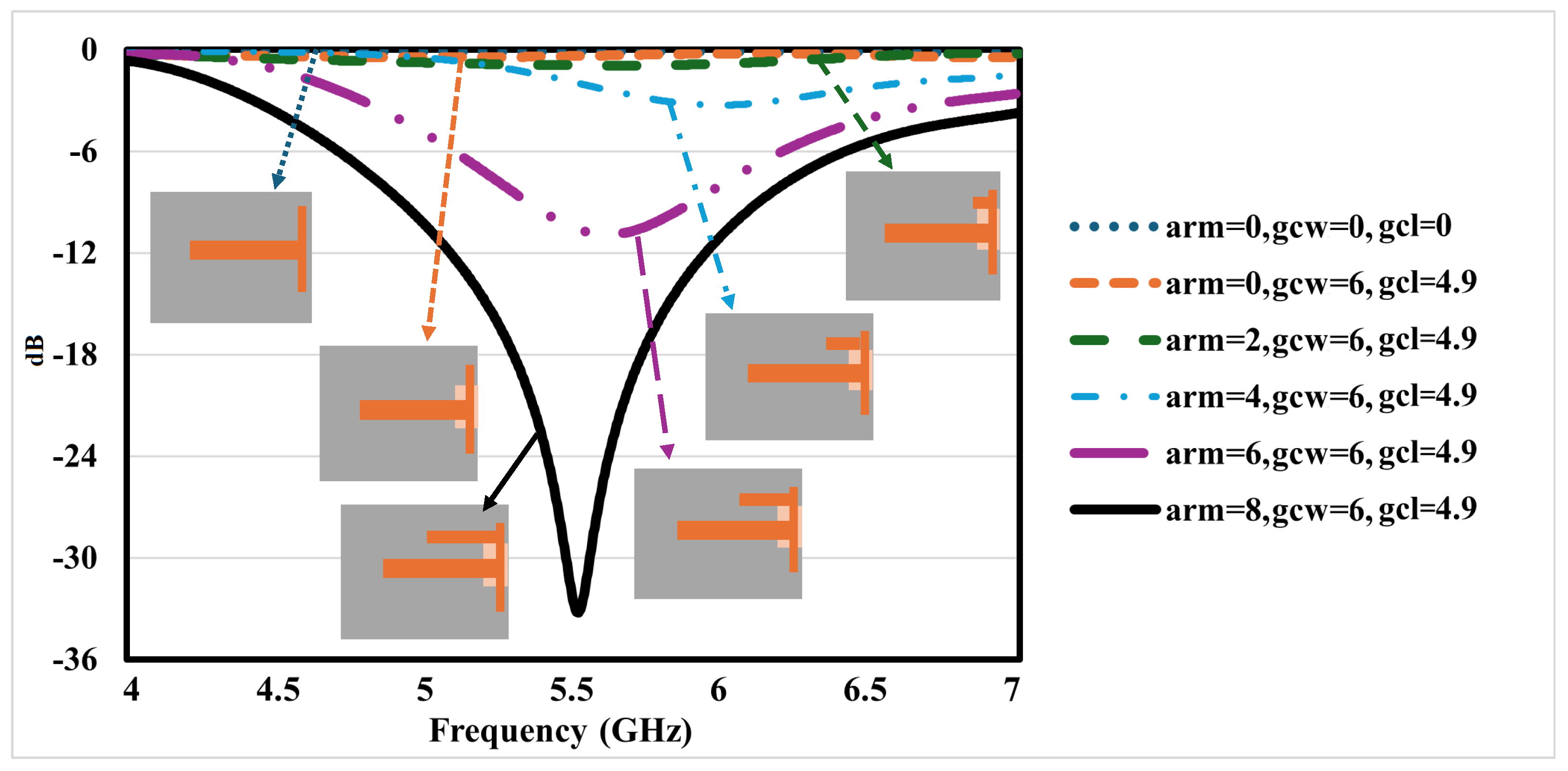
2.1. Evolution of the Pi-Shaped Antenna Design

The design of the Pi-shaped antenna evolved through a series of modifications, starting from a basic T-shaped structure and gradually incorporating changes to enhance the performance in terms of return loss. The process is outlined in the following steps:
Starting with a Simple T-Shaped Antenna: Initially, the antenna had a T-shaped radiating structure with no modifications to the ground plane. At this stage, the performance was limited due to poor impedance matching and insufficient return loss.
Introducing a Ground Cut for Performance Improvement: A ground cut was added to help redistribute current flow and enhance impedance matching. The width of the ground cut (gcl) and length of the ground cut (gcw) were optimized to 4.9 mm and 6 mm, leading to better resonance at target frequencies; a detailed explanation of ground cut dimension optimization is included in Section 2.2.
Gradual Addition of Arms for Bandwidth Enhancement: Additional elements (arms) were incrementally introduced (arm = 2, 4, 6) to fine-tune the resonance characteristics. This step ensured better impedance matching and improved return loss.
Final Optimization into a Pi-Shaped Structure: The final design, incorporating an 8 mm arm, demonstrated the best performance with a significant resonance dip around 5.5 GHz. The Pi shape, combined with the optimized ground cut, provided an efficient current path, enhancing the overall performance.
By following this structured progression, the reflection coefficient of the single antenna was transformed from a basic T-shape to a fully optimized Pi-shaped structure, as shown in Figure 4, achieving better impedance matching and enhanced return loss. This makes it a highly effective design for next-generation wireless applications.

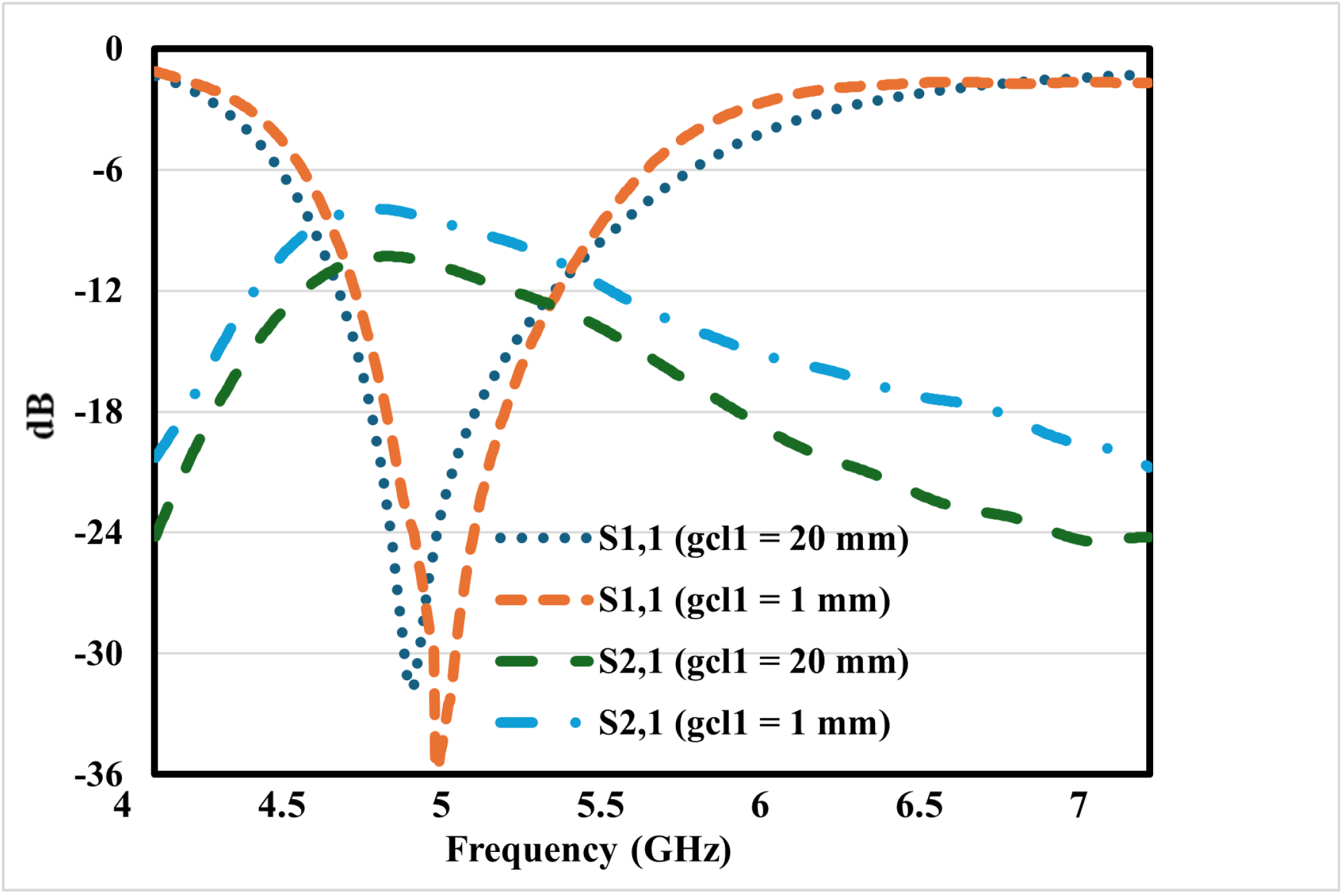
2.2. Optimization of Ground Slot Dimensions

The proposed single-element antenna was analyzed according to the ground cut, varying two parameters in two steps, to achieve the upper mid-band conveniently. In the first step 1, from Figure 5a, the ground cut width (gcl) was varied to analyze the frequency shift, but by varying the width from 4.8 mm to 5.0 mm, there was a minor shift for both values not in the desired range. And in step 2, the Pi-shaped patch antenna’s ground slot length (gcw) varied from 5.5 mm to 6.5 mm; the reflection coefficient is shown by a solid black color in Figure 5b for the desired range, where increasing the value shifted to higher frequencies and decreasing the ground cut length showed a minor shift to lower frequencies.

2.3. Effect of Decoupling Structure

The Figure 6 illustrates how integrating a decoupling structure significantly enhanced the S-parameters of the MIMO antenna system. Notably, the S 2 , 1 parameter, which represents mutual coupling between antenna elements, showed a significant reduction when the decoupling structure was applied (gcl1 = 20 mm), indicating improved isolation. This enhancement is crucial for MIMO performance, as lower coupling leads to better signal quality and reduced interference between antenna elements. Additionally, the improved S 1 , 1 parameter suggests better impedance matching, leading to more efficient signal transmission and reception. Overall, incorporating a decoupling structure helps optimize signal integrity, boost diversity performance, and enhance system efficiency, making it an essential design choice for next-generation wireless communication systems like 5G and beyond.

3. Results and Discussion
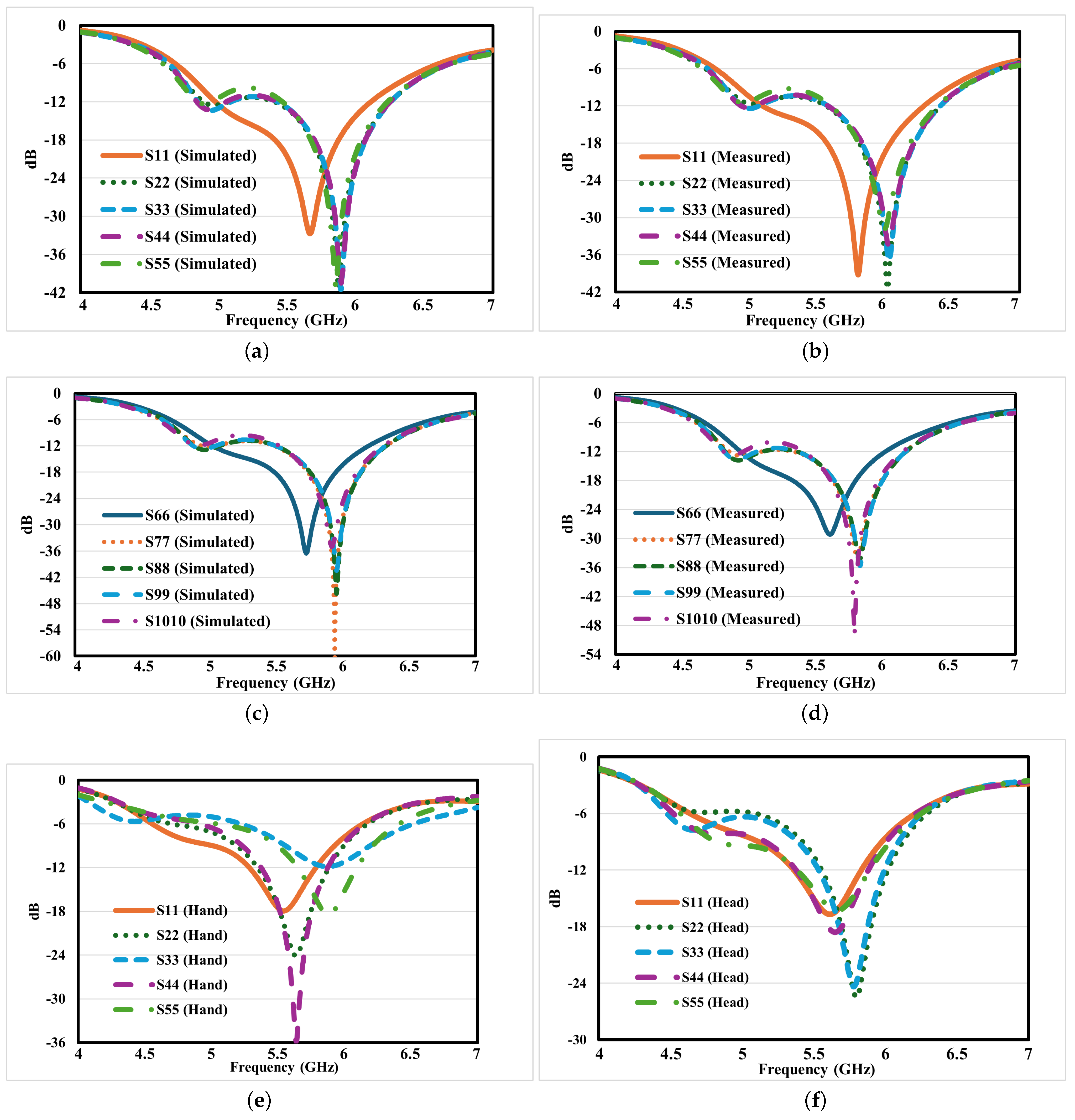
In this section, we will discuss simulated and measured results, as well as the SAR analysis of the MIMO antenna array in the presence of a hand and head, to analyze the performance for future-generation upper mid-band applications.

3.1. S-Parameters

For the purpose of comparison, the simulated results with the measured ones, the S-parameters for left-sided ports (Port 1 to 5), S 11 , S 22 , S 33 , S 44 , and S 55 have been depicted in Figure 7a,b, and for right-sided ports (Port 6 to 10), S 66 , S 77 , S 88 , S 99 , S 1010 , are shown in Figure 7c and Figure 7d, respectively. The plots indicate a discrepancy of about 150 MHz for almost all measured values from their corresponding simulated counterparts, primarily due to SMA connector soldering as well as mild fabrication and measurement errors. Nevertheless, the simulated reflection coefficient continued to increase beyond unity, and the measured reflection coefficient also increased, with both operating within the upper mid-band frequency range. Additionally, the above proposed antenna was modeled for the presence of hand and head models, and the reflection coefficients are reported in Figure 7e,f. In both cases, the reflection coefficient values were still rising slightly across the desired frequency range.
The simulated and measured transmission curves with respect to isolation also presented performance of the antenna that all the values of S 12 , S 13 , S 14 , S 15 , S 16 , and S 23 were below −10 dB at the entire operating bandwidth, as shown in Figure 8a,b. Specifically, a low S 12 value shows that the isolation between the antenna ports is very good if it is below −10 dB (VSWR 3:1), which is a requirement for highest MIMO performance. These results provide practical evidence regarding the feasibility of the fabrication and measurement procedures, demonstrating that the given antenna provides high performance and excellent isolation. These results also confirm high suitability of the proposed configuration for achieving the required frequency in modern 5G NR applications.

3.2. Realized Gain

The realized gain performance of the proposed multi-port MIMO antenna array highlights its suitability for future-generation wireless applications. The gain varied across different ports, showcasing the antenna’s ability to deliver stable radiation characteristics. Among the ports, Port 10 achieved the highest realized gain of around 4.5 dBi at 5.9 GHz, ensuring strong signal reception and transmission, while Port 2 registered the lowest gain at approximately 0 dBi at 4.7 GHz, as presented in the Figure 9, indicating some variations in radiation efficiency. Despite these differences, the overall gain remained well within an acceptable range, supporting reliable connectivity, enhanced spatial diversity, and improved signal coverage. This multi-port design effectively operates across multiple frequency bands, making it an excellent candidate for next-generation 5G communication systems and beyond.

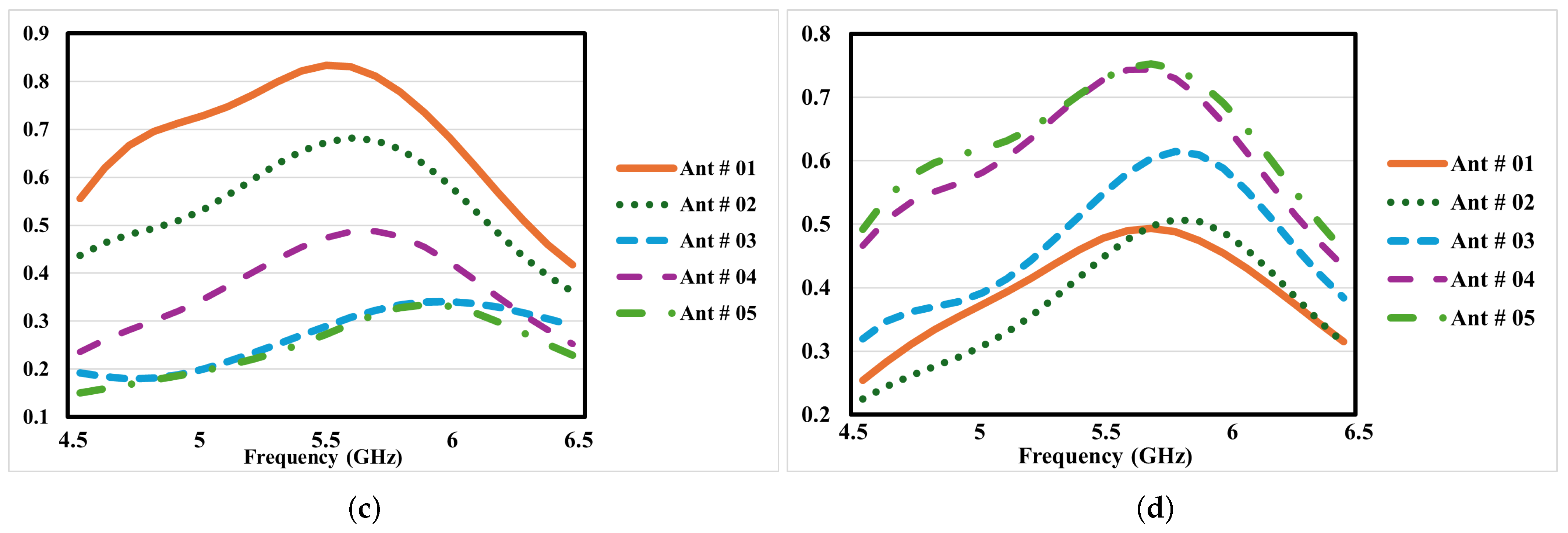
3.3. Total Efficiency

The total efficiency of an antenna is one performance factor that defines the general performance of an antenna in any communication system. In fact, it measures the portion of power that is actually emitting from the antenna to the power fed to it, combining the effects of the radiation efficiency and the impedance mismatch. In the proposed ten-port MIMO antenna system, the total efficiency values varied from 76.12% to 91.57% for all the operating bands of interest, emphasizing the upper mid-band region performance of the proposed design, as shown in Figure 10. This high efficiency translates to low power losses, a factor that makes the antenna very appropriate for next-generation wireless applications that require efficient, low-power systems. Various aspects such as effective design of the stacked geometry of the PCB, effective design of the feed lines, and efficient decoupling play a critical role in attaining such efficiency. The efficiency of all the bands under the LTE was considerably constant; the LTE 46, LTE 47, and n102 all performed efficiently, making the product reliable and apt for multi-national compact devices such as smartphones that function in multi-bands.

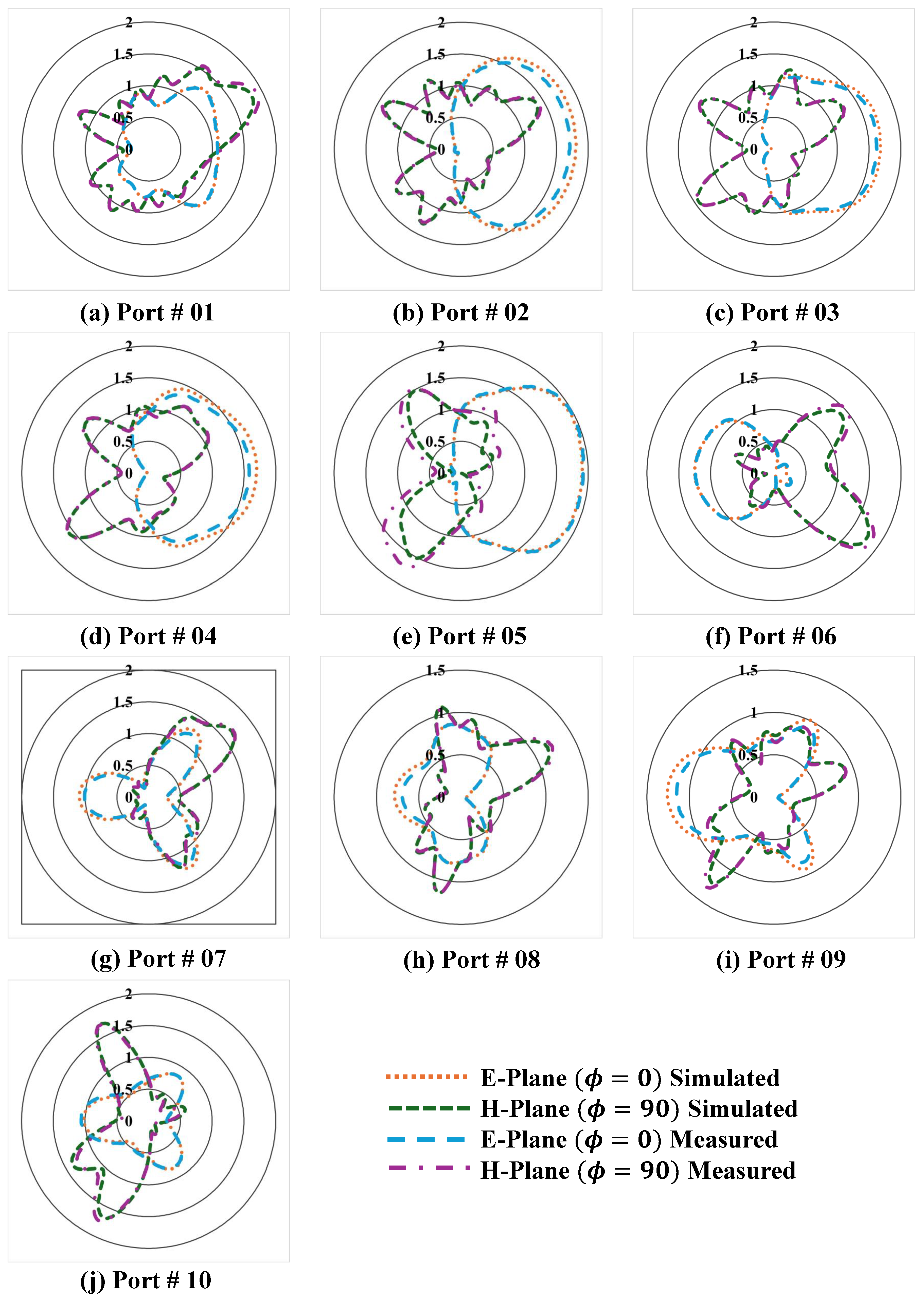
3.4. Radiation Pattern

Thus, to understand the radiation behavior of the antenna well, the far-field radiation patterns are shown in Figure 11 at the resonance frequency both for the E-plane and H-plane. During the simulations and measurements, one of the antenna ports was activated with a load of 50 ohms. The proposed antenna showed near-stable E-plane directional radiation patterns close to resonance. Also, the H-plane radiation pattern at 5.8 GHz was again bidirectional, with a distinctly recognizable and integrated pattern.
These results show that the developed antenna provides acceptable radiation characteristics in the studied frequency bands to be used in practical systems or measurement setups, as shown in Figure 3c. From the stable H-plane pattern, the usefulness of the antenna in providing directional coverage as required in certain application environments is evident, while the E-plane patterns to different frequencies give a glimpse of its directional pattern at the higher frequencies.

Envelope Correlation Coefficient (ECC)

By applying Equation (1), the ECC evaluates the S-parameters matrix; its methodological background has been discussed in [11]. Substituting this into the above equation, the ECC ( ρ ) values were computed and are shown in Figure 12, where the ECC values of antennas 1 to 5 are shown, which indicates that both the simulated and measured ECC values are less than 0.03—as shown in Figure 12. These measured ECC values were obtained from the measured reflection coefficients given by Equation (1).
ρ e i j = | S i i S i j + S j i S j j | 2 ( 1 | S i i | 2 | S j i | 2 ) ( 1 | S j j | 2 | S i j | 2 )

3.5. Diversity Gain

Diversity gain (DG) plays a vital role in assessing the effectiveness of multi-port MIMO antenna arrays, especially for next-generation wireless applications that require reliable and efficient communication. The proposed MIMO antenna array achieved a simulated DG close to the ideal 10 dB across its frequency range from the S-parameters D G = 10 × 1 | E C C | 2 , as depicted in Figure 13, ensuring strong signal reception while reducing the impact of signal fading from [11]. The plotted DG values for different antenna port combinations remain stable, highlighting the antenna’s ability to counteract multi-path interference in complex wireless environments. This exceptional diversity performance makes the antenna well suited for advanced communication systems like 5G and beyond, where high-speed data transmission, stable connectivity, and optimal spectrum use are critical.

3.6. SAR Analysis

Preliminary results of the SAR analysis for the proposed antenna design near human tissue are a significant factor for determining the safety and performance of the proposed antennas. In the proposed MIMO antenna system, the SAR values were analyzed under two scenarios: There were two types examined, namely, hand simulation and head simulation. In the case of hand simulation for a 1-g tissue, the maximum and minimum SAR values were found to be 0.118 W/kg and 0.0606 W/kg, respectively, as shown in Figure 14. Likewise for a head simulation of a 10-g tissue, the maximum and minimum SAR values reported were 18.7 W/kg and 1.72 W/kg, as shown in Figure 15. These results confirm that the system’s radiation level is within SAR regulatory limits and prove that the system can safely function in typical environments. The low SAR values demonstrated in the hand simulations thus confirm the antenna’s appropriateness for handheld devices, while the performance observed in the head simulations shows its application in smartphones. In realizing low SAR values and sustaining good efficiency and isolation of the antennas, the presented design provides safety for users and effectiveness for future wireless communications.
Recent research on MIMO antennas for 5G smartphones has placed significant emphasis on SAR (specific absorption rate) assessment to ensure both high-performance connectivity and user safety. The study “High Performance Eight-Port Dual-Band MIMO Antenna System for 5G Devices” [36] explored an eight-port antenna system, optimizing isolation to achieve lower SAR values while maintaining reliable performance. Similarly, “SAR Assessment of Miniaturized Wideband MIMO Antenna Structure for Millimeter Wave 5G Smartphones” [37] focused on the impact of compact MIMO designs operating at millimeter-wave frequencies, ensuring that device miniaturization did not compromise safety compliance. The research “Dual-Band Ten-Element MIMO Array Based on Dual-Mode IFAs for 5G Terminal Applications” [26] evaluated SAR levels for a ten-element MIMO array, demonstrating an effective balance between radiation efficiency and user exposure limits. Likewise, “High-Isolation Eight-Element MIMO Array for 5G Smartphone Applications” [38] examined isolation techniques and their role in reducing the SAR, ensuring compliance with safety regulations while enhancing antenna performance. These studies align with our research, as we also focus on SAR optimization through strategic antenna placement, decoupling techniques, and miniaturization. Our findings contribute to this ongoing research by offering a comprehensive evaluation of SAR mitigation strategies in modern MIMO antenna designs for 5G smartphones.

3.7. Comparison

A comparison of the proposed antenna system’s performance with existing 5G antennas is presented in Table 2 below. The proposed antenna is tuned for the 4.7–6.5 GHz frequency band, thus having a fractional bandwidth of 32.72%, while the comparative studies of the proposed antenna with the other designs mentioned in [11,39] show that the presented designs have lower bandwidths of 46.96% and 11.11%, respectively. The proposed system also ensures an isolation of >10 dB; however, this is slightly less than the isolation of >17 dB and >20 dB realized in [11,39], respectively, but is adequate for MIMO operation. Furthermore, the ECC for the proposed designs is <0.03, which is very good MIMO diversity and is superior to <0.002 in [11] and <0.01 in [39]. The overall efficiency of the proposed antenna varies between 76.12% and 91.57%. However, compared to other equivalent designs of [11] (64–82%) and [40](53–86%), it can be concluded that the proposed antenna design is suitable for high-performance 5G applications. In summary, the proposed design solution provides a reasonable bandwidth, isolation, and efficiency that guarantee its competitiveness in the sphere of prospective next-generation wireless communication systems.

4. Conclusions

In the present work, an effective ten-element MIMO antenna system that is Pi-shaped has been designed, modeled, and tested for the upper mid-band of smartphones in the next generation. The proposed system also implants the LTE 46 (5.15–5.925 GHz), LTE 47 (5.855–5.925 GHz), and n102 (5.925–6.425) GHz, with the help of which it has a fractional bandwidth of 32.7%. Based on the isolation and averaged efficiency results of the proposed antenna system, which is better than 10 dB and ranges from 76.12 to 91.57%, it reveals that the proposed antenna system lends itself to wideband applications in modern communication systems. The overall size of antenna array is 125 mm × 70 mm using RT/5880 as the dielectric material, which fits into current and future smartphone applications. Thus, through adopting a decoupling structure, the self-coupling between the adjacent antennas is significantly minimized, thus maintaining the operation functionality of the MIMO system. The reflection coefficients, radiation patterns, and efficiency measurements attest to the efficacy of the proposed design. For 1 g tissue, the maximum and minimum SARs obtained in the hand simulation are 0.118 W/kg and 0.0606 W/kg, while for 10 g tissue in the presence of head simulation, they are 18.7 W/kg and 1.72 W/kg, respectively. In this work, high-isolation, compact, and wideband design issues have been discussed for the Pi-shaped MIMO antenna as a promising solution for the design of future massive connectivity communication systems with comparatively high data rates.

Author Contributions

Conceptualization, M.Z.; Formal analysis, Y.A.; Methodology, M.Z.; Software, M.Z.; Validation, Y.A.; Writing—original draft, M.Z.; Writing—review and editing, Y.A. All authors have read and agreed to the published version of the manuscript.

Funding

This research received no external funding.

Data Availability Statement

No new data were created or analyzed in this study. Data sharing is not applicable to this article.

Conflicts of Interest

All authors declare that they have no competing interests.

References

  1. Zahid, M.N.; Gaofeng, Z.; Kiani, S.H.; Rafique, U.; Abbas, S.M.; Alibakhshikenari, M.; Dalarsson, M. H-Shaped Eight-Element Dual-Band MIMO Antenna for Sub-6 GHz 5G Smartphone Applications. IEEE Access 2022, 10, 85619–85629. [Google Scholar] [CrossRef]
  2. Kulkarni, N.; Linus, R.M.; Bahadure, N.B. A Small Wideband Inverted L-Shaped Flexible Antenna for Sub-6 GHz 5G Applications. AEU-Int. J. Electron. Commun. 2023, 159, 154479. [Google Scholar]
  3. Fang, Y.; Liu, Y.; Jia, Y.; Liang, J.; Zhang, H.H. Reconfigurable Structure Reutilization Low-SAR MIMO Antenna for 4G/5G Full-Screen Metal-Frame Smartphone Operation. Antennas Wirel. Propag. Lett. 2023, 22, 1219–1223. [Google Scholar]
  4. Desai, A.; Kulkarni, J.; Kamruzzaman, M.M.; Hubalovsky, S.; Hsu, H.-T.; Ibrahim, A.A. Interconnected CPW Fed Flexible 4-Port MIMO Antenna for UWB, X, and Ku Band Applications. IEEE Access 2022, 10, 57641–57654. [Google Scholar]
  5. Abubakar, H.S.; Zhao, Z.; Wang, B.; Kiani, S.H.; Parchin, N.O.; Hakim, B. Eight-Port Modified E-Slot MIMO Antenna Array with Enhanced Isolation for 5G Mobile Phone. Electronics 2023, 12, 316. [Google Scholar] [CrossRef]
  6. Shankar Das, G.; Bikash Chamuah, B.; Beria, Y.; Protim Kalita, P.; Buragohain, A. Compact Four Elements SUB-6 GHz MIMO Antenna for 5G Applications. Mater. Today Proc. 2023, in press.
  7. Kumar, P.; Pathan, S.; Kumar, O.P.; Vincent, S.; Nanjappa, Y.; Kumar, P.; Shetty, P.; Ali, T. Design of a Six-Port Compact UWB MIMO Antenna with a Distinctive DGS for Improved Isolation. IEEE Access 2022, 10, 112964–112974. [Google Scholar]
  8. Saurabh, A.K.; Meshram, M.K. Compact Sub-6 GHz 5G-Multiple-input-multiple-output Antenna System with Enhanced Isolation. Int. J. RF Microw. Comput. Aided Eng. 2020, 30, e22246. [Google Scholar]
  9. Kulkarni, J.; Alharbi, A.G.; Desai, A.; Sim, C.-Y.-D.; Poddar, A. Design and Analysis of Wideband Flexible Self-Isolating MIMO Antennas for Sub-6 GHz 5G and WLAN Smartphone Terminals. Electronics 2021, 10, 3031. [Google Scholar] [CrossRef]
  10. Roshani, S.; Koziel, S.; Yahya, S.I.; Chaudhary, M.A.; Ghadi, Y.Y.; Roshani, S.; Golunski, L. Mutual Coupling Reduction in Antenna Arrays Using Artificial Intelligence Approach and Inverse Neural Network Surrogates. Sensors 2023, 23, 7089. [Google Scholar] [CrossRef]
  11. Zahid, M.; Ali, Q.; Bhowmike, N.; Bolla, D.P.; Shoaib, S.; Amin, Y. Dual-Band MIMO Antenna for N79 and Sub-7 GHz Smartphone Applications. Electronics 2024, 13, 2724. [Google Scholar] [CrossRef]
  12. Jemaludin, N.H.B.; Al-Gburi, A.J.A.; Elabd, R.H.; Saeidi, T.; Akbar, M.F.; Ibrahim, I.M.; Zakaria, Z. A comprehensive review on MIMO antennas for 5G smartphones: Mutual coupling techniques, comparative studies, SAR analysis, and future directions. Results Eng. 2024, 23, 102712. [Google Scholar]
  13. Dubazane, S.P.; Kumar, P.; Afullo, T.J.O. Metasurface Superstrate-based MIMO Patch Antennas with Reduced Mutual Coupling for 5G Communications. ACES J. 2022, 37, 408–419. [Google Scholar]
  14. Riaz, M.J.; Sultan, A.; Zahid, M.; Javed, A.; Amin, Y.; Loo, J. MIMO Antennas for Future 5G Communications. In Proceedings of the 2020 IEEE 23rd International Multitopic Conference (INMIC), Bahawalpur, Pakistan, 5–7 November 2020; pp. 1–4. [Google Scholar] [CrossRef]
  15. Ahmed, M.; Zafar, Z.; Javed, I.; Zahid, M.; Amin, Y. 12 Element Inverted E-Shaped Massive MIMO Antennas for Future 5G Smartphone Applications. In Proceedings of the 2023 7th International Multi-Topic ICT Conference (IMTIC), Jamshoro, Pakistan, 10–12 May 2023; pp. 1–5. [Google Scholar] [CrossRef]
  16. Lin, Z.; Niu, H.; An, K.; Wang, Y.; Zheng, G.; Chatzinotas, S.; Hu, Y. Refracting RIS-Aided Hybrid Satellite-Terrestrial Relay Networks: Joint Beamforming Design and Optimization. IEEE Trans. Aerosp. Electron. Syst. 2022, 58, 3717–3724. [Google Scholar] [CrossRef]
  17. Sun, L.; Li, Y.; Zhang, Z. Wideband decoupling of integrated slot antenna pairs for 5G smartphones. IEEE Trans. Antennas Propag. 2021, 69, 2386–2391. [Google Scholar] [CrossRef]
  18. Chang, L.; Yu, Y.; Wei, K.; Wang, H. Orthogonally polarized dual antenna pair with high isolation and balanced high performance for 5G mimo smartphone. IEEE Trans. Antennas Propag. 2020, 68, 3487–3495. [Google Scholar] [CrossRef]
  19. Cheng, B.; Du, Z. A wideband low-profile microstrip mimo antenna for 5G mobile phones. IEEE Trans. Antennas Propag. 2021, 70, 1476–1481. [Google Scholar]
  20. Babashah, H.; Hassani, H.R.; Mohammad-Ali-Nezhad, S. A compact uwb printed monopole mimo antenna with mutual coupling reduction. Prog. Electromagn. Res. C 2019, 91, 55–67. [Google Scholar] [CrossRef]
  21. Ali, A.; Munir, M.E.; Marey, M.; Mostafa, H.; Zakaria, Z.; Al-Gburi, A.J.A.; Bhatti, F.A. A Compact MIMO Multiband Antenna for 5G/WLAN/WIFI-6 Devices. Micromachines 2023, 14, 1153. [Google Scholar] [CrossRef]
  22. Sun, L.; Li, Y.; Zhang, Z.; Iskander, M.F. A compact planar omnidirectional mimo array antenna with pattern phase diversity using folded dipole element. IEEE Trans. Antennas Propag. 2018, 67, 1688–1696. [Google Scholar] [CrossRef]
  23. Jaglan, N.; Gupta, S.D.; Kanaujia, B.K.; Sharawi, M.S. 10 element sub-6-GHz multi-band double-t based mimo antenna system for 5G smartphones. IEEE Access 2021, 9, 118662–118672. [Google Scholar] [CrossRef]
  24. Pei, T.; Zhu, L.; Wang, J.; Wu, W. A low-profile decoupling structure for mutual coupling suppression in mimo patch antenna. IEEE Trans. Antennas Propag. 2021, 69, 6145–6153. [Google Scholar] [CrossRef]
  25. Hei, Y.Q.; He, J.G.; Li, W.T. Wideband decoupled 8-element mimo antenna for 5G mobile terminal applications. IEEE Antennas Wirel. Propag. Lett. 2021, 20, 1448–1452. [Google Scholar] [CrossRef]
  26. Hu, W.; Liu, X.; Gao, S.; Wen, L.-H.; Qian, L.; Feng, T.; Xu, R.; Fei, P.; Liu, Y. Dual-band ten-element mimo array based on dual-mode ifas for 5G terminal applications. IEEE Access 2019, 7, 178476–178485. [Google Scholar] [CrossRef]
  27. Armghan, A.; Lavadiya, S.; Udayaraju, P.; Alsharari, M.; Aliqab, K.; Patel, S.K. Sickle-Shaped High Gain and Low Profile Based Four Port MIMO Antenna for 5G and Aeronautical Mobile Communication. Sci. Rep. 2023, 13, 15700. [Google Scholar] [CrossRef] [PubMed]
  28. Ullah, A.; Ojaroudi Parchin, N.; Amar, A.S.I.; Abd-Alhameed, R.A. Eight-Element Antenna Array with Improved Radiation Performances for 5G Hand-Portable Devices. Electronics 2022, 11, 2962. [Google Scholar] [CrossRef]
  29. Yuan, X.-T.; He, W.; Hong, K.-D.; Han, C.-Z.; Chen, Z.; Yuan, T. Ultra-Wideband MIMO Antenna System with High Element-Isolation for 5G Smartphone Application. IEEE Access 2020, 8, 56281–56289. [Google Scholar] [CrossRef]
  30. Sim, C.-Y.-D.; Liu, H.-Y.; Huang, C.-J. Wideband MIMO Antenna Array Design for Future Mobile Devices Operating in the 5G NR Frequency Bands N77/N78/N79 and LTE Band 46. Antennas Wirel. Propag. Lett. 2020, 19, 74–78. [Google Scholar] [CrossRef]
  31. Mishra, P.; Kulat, K.D. An Eight-Element MIMO Antenna Array for NR Application. IETE J. Res. 2023, 70, 4562–4571. [Google Scholar] [CrossRef]
  32. Kiani, S.H.; Altaf, A.; Abdullah, M.; Muhammad, F.; Shoaib, N.; Anjum, M.R.; Damaševičius, R.; Blažauskas, T. Eight Element Side Edged Framed MIMO Antenna Array for Future 5G Smart Phones. Micromachines 2020, 11, 956. [Google Scholar] [CrossRef]
  33. Ali, H.; Ren, X.-C.; Hashmi, A.M.; Anjum, M.R.; Bari, I.; Majid, S.I.; Jan, N.; Tareen, W.U.K.; Iqbal, A.; Khan, M.A. An Eight Element Dual Band Antenna for Future 5G Smartphones. Electronics 2021, 10, 3022. [Google Scholar] [CrossRef]
  34. Jiang, J.-Y.; Su, H.-L. A Wideband Eight-Element MIMO Antenna Array in 5G NR N77/78/79 and WLAN-5 GHz Bands for 5G Smartphone Applications. Int. J. Antennas Propag. 2022, 2022, 8456936. [Google Scholar]
  35. Ali, H.; Ren, X.-C.; Bari, I.; Bashir, M.A.; Hashmi, A.M.; Khan, M.A.; Majid, S.I.; Jan, N.; Tareen, W.U.K.; Anjum, M.R. Four-Port MIMO Antenna System for 5G N79 Band RF Devices. Electronics 2021, 11, 35. [Google Scholar] [CrossRef]
  36. Kiani, S.H.; Khan, M.A.; Rafique, U.; Marey, M.; Alharbi, A.G.; Mostafa, H.; Khan, M.A.; Abbas, S.M. High Performance Eight-Port Dual-Band MIMO Antenna System for 5G Devices. Micromachines 2022, 13, 959. [Google Scholar] [CrossRef] [PubMed]
  37. Elabd, R.H.; Al-Gburi, A.J.A. SAR assessment of miniaturized wideband MIMO antenna structure for millimeter wave 5G smartphones. Microelectron. Eng. 2023, 282, 112098. [Google Scholar] [CrossRef]
  38. Jiang, W.; Liu, B.; Cui, Y.; Hu, W. High-Isolation Eight-Element MIMO Array for 5G Smartphone Applications. IEEE Access 2019, 7, 34104–34112. [Google Scholar] [CrossRef]
  39. Jaglan, N.; Gupta, S.D.; Sharawi, M.S. 18 Element Massive MIMO/Diversity 5G Smartphones Antenna Design for Sub-6 GHz LTE Bands 42/43 Applications. IEEE Open J. Antennas Propag. 2021, 2, 533–545. [Google Scholar] [CrossRef]
  40. Dey, S.; Dey, S. Wideband Highly Efficient Eight Element MIMO Antenna Using Differential Fed Open End Slot for Sub-7 GHz 5G Mobile Handset Applications. IEEE Trans. Circuits Syst. II Express Briefs, 2024, early access.
  41. Ren, A.; Yu, H.; Yang, L.; Huang, Z.; Liu, Y.; Hou, J. Massive 16-Element Wideband Decoupled Pairs with High Integration for 5G Smartphones. IEEE Antennas Wirel. Propag. Lett. 2024, 23, 4114–4118. [Google Scholar] [CrossRef]
Figure 1. The flow chart of a proposed Pi-shaped ten-element MIMO antenna array.
Telecom 06 00022 g001
Figure 2. The detailed dimensions of the proposed multi-port MIMO antenna array. (a) 10-port Pi-shaped MIMO structure. (b) Radiator (Patch) dimensions of single antenna. (c) Ground slots parameters.
Telecom 06 00022 g002
Figure 3. The fabricated prototype. (a) Front view. (b) Rear view. (c) Measurement setup.
Telecom 06 00022 g003
Figure 4. Progression of S 1 , 1 to Pi-shaped from simple T shape without ground cut to Pi-shaped with ground cut.
Telecom 06 00022 g004
Figure 5. The variations of the ground slot to achieve the desired frequency band in terms of S 1 , 1 . (a) Reflection coefficient by varying ground cut width (gcl). (b) Reflection coefficient by changing ground cut length (gcw).
Telecom 06 00022 g005
Figure 6. S-parameters improved by incorporating decoupling structure.
Telecom 06 00022 g006
Figure 7. Reflection coefficient of proposed ten-port MIMO antenna array. (a) Simulated reflection coefficient (left side). (b) Measured reflection coefficient (left side). (c) Simulated reflection coefficient (right side). (d) Measured reflection coefficient (right side). (e) Reflection coefficient with hand. (f) Reflection coefficient with head.
Telecom 06 00022 g007
Figure 8. Transmission coefficient of proposed ten-port MIMO antenna array. (a) Simulated transmission coefficient. (b) Measured transmission coefficient. (c) Transmission coefficient with hand. (d) Transmission coefficient with head.
Telecom 06 00022 g008
Figure 9. The realized gain of a proposed MIMO antenna array throughout the obtained frequency band.
Telecom 06 00022 g009
Figure 10. Total efficiency of proposed ten-port MIMO antenna array. (a) Simulated total efficiency. (b) Measured total efficiency. (c) Total efficiency with hand. (d) Total efficiency with head.
Telecom 06 00022 g010aTelecom 06 00022 g010b
Figure 11. The 2D radiation patterns of proposed MIMO antenna array at 5.8 GHz.
Telecom 06 00022 g011
Figure 12. Envelope correlation coefficient of proposed multi-port MIMO antenna array. (a) Simulated reflection coefficient. (b) Measured reflection coefficient. (c) Reflection coefficient with hand. (d) Reflection coefficient with head.
Telecom 06 00022 g012
Figure 13. Diversity gain of a proposed MIMO antenna array throughout the obtained frequency band.
Telecom 06 00022 g013
Figure 14. SAR values of proposed multi-port MIMO antennas for hand simulation.
Telecom 06 00022 g014
Figure 15. SAR values of proposed multi-port MIMO antennas for head simulation.
Telecom 06 00022 g015
Table 1. Ten-element Pi-shaped MIMO antenna array parameters.
VariableDimension (mm)VariableDimension (mm)VariableDimension (mm)
sl125sw70spacing25
pl7.5fl13fs2.63
gcw6gcw11gcs2.085
gcl4.9gcl120arm8
gap1.5gap114.915
Table 2. Performance comparison of various state-of-the-art 5G antennas.
Ref.Frequency (GHz)% BandwidthIsolation (−dB)ECCTotal Eff. (%)
[11]4.4–7.146.96>17<0.00264–82
[39]3.4–3.811.11>20<0.0187
[41]4.4–6.030.77>14.2<0.3246.1–76.9
[40]3.29–6.6167.1>16.6<0.05753–86
Proposed4.7–6.532.72>10<0.0376.12–91.57
Disclaimer/Publisher’s Note: The statements, opinions and data contained in all publications are solely those of the individual author(s) and contributor(s) and not of MDPI and/or the editor(s). MDPI and/or the editor(s) disclaim responsibility for any injury to people or property resulting from any ideas, methods, instructions or products referred to in the content.

