Article

Towards Biomass Gasification Enhanced by Structured Iron-Based Catalysts

Institute of Sciences and Technologies for Sustainable Energy and Mobility-CNR, P.le Tecchio 80, 80125 Naples, Italy
*
Author to whom correspondence should be addressed.
Fuels 2021, 2(4), 546-555; https://doi.org/10.3390/fuels2040032
Submission received: 14 October 2021 / Revised: 9 November 2021 / Accepted: 29 November 2021 / Published: 6 December 2021

Abstract

:
The main drawback for the development of biomass gasification technology is tar conversion. Among the various methods for tar abatement, the use of catalysts has been proposed in the literature. Most of the works reported in the literature on catalytic systems for biomass tar conversion refers to catalysts in the form of powder; however, deactivation occurs by fast clogging with particulates deriving from biomass gasification. The integration of catalytic filter element for particle and tar removal directly integrated into the freeboard of the reactor is a new concept recently proposed and patented. In this context, this paper evaluates the possibility to integrate a structured iron-based catalytic monolith in the freeboard of a fluidized bed gasifier to enhance biomass gasification. The effectiveness of using a monolith for gas conditioning has been preliminarily verified. The limited effect on the gas production and composition seems to be related to the limited range of operating conditions explored in this work rather than to the low activity of the iron-based catalyst. Further studies to optimize the performance and to assess the possible deactivation of the catalyst due to coke deposition must be carried out.

1. Introduction

The main challenge to implement biomass gasification technology is tar conversion to gaseous products. They are in fact unwanted products, as they condense in the coldest parts of the systems, obstructing pipes and filters; they are also highly carcinogenic products, and contain a significant amount of unused energy [1]. Therefore, the generation of condensable products must be limited [2,3,4]. This is a necessity of biomass gasification processes, whatever the final use of the gas produced (use in gas turbines, fuel for engines, fuel cells, methanol synthesis, Fischer-Tröpsch synthesis). Among the various methods of tar abatement, the use of catalysts has been proposed in the literature, which has the advantage of recovering the energy content of tar, converting them into gaseous products at temperatures below 900 °C [5]. Tar is generally converted by reforming reactions; thus, nickel-based catalysts are mainly applied [5,6,7,8,9,10].
Depending on whether the catalyst is placed in a reactor downstream of the gasifier or directly in the gasifier, we are talking about secondary or primary treatment methods, respectively. The majority of the works reported in the literature on the study of catalytic systems for the conversion of biomass tar refers to catalysts in the form of powders, although they, in the case of secondary systems, cannot be used in the presence of particulates deriving from biomass because they can become clogged. Therefore, it would be necessary to filter the gas coming from the gasifier before their entry into the secondary reactor. Hot gas particulate cleanup is one of the most important improvements to commercial applications of biomass and coal gasification in the past 30 years [11]. This operation should then be carried out with filtering systems operating at high temperatures (400–550 °C), which themselves can face clogging/deactivation problems by the coke that can form as a result of any cracking reactions of the tar contained in the gas stream to be filtered [12,13]. Catalytic filter candles are an innovative solution for hot gas cleaning and conditioning; the integration of the catalytic filter element (mainly based on Ni as active phase) for particle and tar removal directly integrated into the freeboard of reactor is a new concept recently proposed and patented [14,15].
The performances of catalytic hot filters has been investigated by carrying out experiments with both tar model compounds and real syngas streams [16,17]. More specifically, Nacken et al. [17] studied the performance of two nickel based catalytic filter configurations using naphthalene as model tar compound; the best performance was obtained with a candle filled with a fixed bed catalyst, showing a tar conversion higher than the most catalytically active candle (i.e., a candle impregnated with a catalytically active phase). Rapagnà et al. [16] showed that a tar concentration of 1 g/Nm3 can be obtained using nickel impregnated filters located in the freeboard of a fluidized bed gasifier. The authors also showed a stable performance under 22 h work.
de Diego and coworkers analyzed four different catalytic filter configurations for in-situ tar removal during dual fluidized bed gasification [18]. They showed that the configuration obtained by coupling a catalytically active filtering candle with a structured Ni-based alumina foam tube placed inside the filtering element allowed for a 95% tar conversion, thus reducing the tar concentration to 0.2 g/Nm3.
Recently, good performance was obtained using real syngas by Rapagnà e coworker with a catalytic filter system realized by filling the inner empty space of commercial ceramic filtering candles with pellets of a catalyst [19]; the highest tar reduction corresponded to a residual tar concentration equal to 250 mg/Nm3, comparable to results reported by de Diego et al. [18].
Another approach to the solution of this type of problem could be to use catalysts in the form of monoliths with a honeycomb structure.
On the other hand, the studies concerning structured secondary catalytic systems, i.e., catalysts in which the active phase is deposited onto a block of ceramic material (generally cordierite), are few [6,12,20,21]. Very recently, Tian et al. [6] proposed the use of biomimetic biochar monoliths as supports for Ni-catalysts to be used for tar abatement. In particular, the authors explored the possibility to use monoliths prepared by carbonization of round pinewood sticks and impregnated with nickel. The best tar conversion efficiency (i.e., the tar amount converted in the presence of the catalyst with respect to the tar amount produced in the absence of the catalyst) corresponded to about 88%.
It is worth noting that the structured catalysts are generally placed downstream from the filtering system, requiring a dedicated temperature control [6,12,20,21].
According to the above considerations, the analysis of the literature suggests an “empty space”: the use of structured catalysts downstream of the gasifier, i.e., in the freeboard just above the fluidizing bed. Structured catalysts generally offer good compactness and low pressure drops [22,23,24,25], which are features of interest in the post-treatment of biomass-derived syngas; moreover, by means of a proper selection of the structure (honeycomb, foam, etc.) and of the channel characteristic diameter, they can be applied for the treatment of a gas rich in particulate matter, without clogging problems that occur for more traditional catalytic packed beds. It is thus possible to avoid the use of expensive and delicate hot filtering systems (operating at 400–550 °C) which can easily become blocked due to the cracking reactions of the tar contained in the gas stream [12,13]. Based on these considerations, it is even more interesting to place a structured catalyst directly on the freeboard of a fluidized bed reactor, thus integrating the cleaning/upgrading stage. Additionally, integration of the structured catalyst within the freeboard allows for a better thermal management, because the catalytic section can be operated at high temperature without requiring additional temperature control devices.
In this work we preliminary evaluate the suitability of enhancing biomass gasification by placing a structured catalytic monolith in the freeboard of a fluidized bed gasifier. To the best of our knowledge, this is the first work proposing this approach. As active phase, an iron-based catalyst was chosen due to its interesting activity, low price and low environmental impact [26] and prior use as a powder [26,27,28]. In particular, the aim is to improve tar abatement; moreover, the effect of the structured catalyst on the syngas composition is addressed.

2. Materials and Methods

2.1. Catalyst Preparation

A 3 wt.% Fe/γ-Al2O3 structured catalyst was used to carry out tests of enhanced biomass gasification. The active layer was deposited onto a 600 cpsi honeycomb cordierite monolith (NGK) in the shape of a cylinder (length, 20 mm; diameter, 17 mm). The preparation method was similar to that reported in previous works [29,30]. Briefly, a γ-Al2O3 (Sasol) layer was first deposed onto the cordierite walls by a dip-coating procedure. Then, the monoliths were impregnated with iron(III) nitrate nonahydrate (Aldrich, >99.99%) in aqueous solution (32 g/L). Drying in a stove at 120 °C and calcination at 800 °C for 3 h under flowing air were carried out in order to obtain the iron oxide. The procedure (impregnation, drying, calcination) was repeated until the desired iron content was reached, corresponding to about 0.3 g of catalyst onto the substrate. It is worth noting that the iron content was similar to that used for the iron based catalyst previously developed as powder [26]. Figure 1 shows images of blank monoliths and prepared structured catalysts, showing the typical red color due to iron oxide.

2.2. Gasification Tests

2.2.1. Standard Tests

The gasification tests were carried out in a pre-pilot bubbling fluidized bed gasifier (BFB) previously developed [28]. The BFB reactor is made by connecting two vertical stainless steel tubes with different diameters (I. D. of 140 mm and I. D. 200 mm respectively) for a total height of 3000 mm. To introduce the pellet in the reactor, an under-bed feeding system was adopted. The syngas leaving the reactor was burned by a flare using an LPG pilot flame prior to being emitted in the atmosphere. A de-dusting treatment of the syngas was performed by a cyclone heated at 450 °C to prevent tar condensation. CO, CO2, and CH4 composition were continuously monitored by an on-line ABB (AO2020) analyzer equipped with an infrared (IR) detector. The analysis system also measures H2 concentration with a thermal conductivity. The gaseous products were also collected by means of 3 L bags and were off-line analyzed by gas microGC (Agilent 3000A). The procedure of the gasification test was the following: (i) the reactor was electrically heated up to the selected temperature, (ii) the fluidization air flow was prepared and established at the assigned value, (iii) the biomass feeding was started, (iv) the tar and fine sampling started when steady conditions were reached. The tar sampling was isokinetically performed by inserting a probe in the reactor from the top (1 m inside) and using a high precision pump (Zambelli PF 12000-02) for the sampling of the stream. Condensable species were separated through a two step-condenser, the first one at ambient temperature for heavier tars, and the second one at −10 °C for lighter ones. A sampling time interval of about 20 min was used to collect the tar, as well as to determine the solids elutriation rates.
The collected liquid and solid were weighed and the tar and fine concentration (g/Nm3) on a dry basis (db) were calculated as the ratio of weight of the sampled tars and solids and the total volume of the collected gas. Additional details on the experimental apparatus are reported in [28].
Gasification tests have been carried out at 830 °C using quartzite as bed materials sand (density = 2600 kg/m3; average particle size φ = 300 μm; minimum fluidization gas velocity umf = 3.8 cm/s at 830 °C) and a home-made iron based catalyst (density = 1800 kg/m3, average particle size φ= 150 μm, minimum fluidization velocity umf = 0.6 cm/s at 830 °C) prepared and characterized as reported in [26]. Briefly, the iron alumina supported catalyst was synthetized by wet impregnation, adding the support (γ-alumina PURALOX SCCA-150/200, Sasol, Sandton (South Africa)) to a solution of iron nitrate Fe(NO3)3·9 H2O (98%, Sigma-Aldrich, St. Louis, MI, USA). The amount of iron was 2.9 wt.% (ICP-MS quantification by Agilent 7500CE instrument). The catalyst had been calcined at 800 °C before use.
In all tests, air as a gasifying agent has been used at a fixed equivalent ratio (ER) and two different gas velocities (0.3 and 0.17 m/s). Similar tests have been reported in [27].
Commercial spruce wood pellets have been feed to the gasifier with a mass flow rate of 4.6 kg/h. The main properties of the pellets used as feedstock, characterized as reported in [26], are shown in Table 1.
Each test was repeated three times in order to evaluate reliability of results; mean value, standard deviation, and error (calculated as standard deviation divided by mean value) for gas species and tar concentrations were calculated and reported in Table S1 (Supplementary Material). Error for gaseous species was lower than 5%, while error for tar concentration was lower than 10%.

2.2.2. Enhanced Gasification Tests

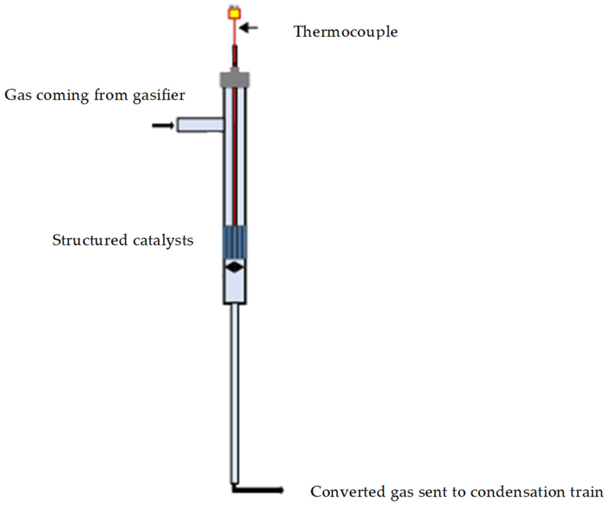
Gasification tests enhanced by structured catalytic reactors were carried out by simulating the positioning of the monolith in the freeboard of the gasifier by inserting a quartz reactor, containing the catalytic monolith, on the tar sampling line out of the gasifier before the condenser train (as previously described). A schematic representation of the catalytic section is reported in the Figure 2. The quartz reactor is in turn housed in a heated oven so that it can be heated to the same temperature as the gasifier freeboard during the test. A fraction (controlled by a precision pump) of the flow gases leaving the gasifier passes through the heated catalytic monolith and is sent to the condensation train. Two different space velocity have been realized by changing the fraction of gas sent to monolith. The liquids were collected according to the standard procedure and the outgoing gases were sent to the analyzer, as reported in the previous section. Gas bags were also taken for analysis with the microGC, as occurring for the standard tests.
Each test was repeated three times in order to evaluate the reliability of results; mean value, standard deviation, and error (calculated as standard deviation divided by mean value) for gas species and tar concentrations were calculated and reported in Table S1 (Supplementary Material). Error for gaseous species was lower than 5%, while error for tar concentration was lower than 10%.

3. Results

Tests were carried out in the presence and in the absence of monoliths, as reported in Section 2, under the experimental conditions reported in Table 1. In particular, two monoliths having an active phase content equal to 650 mg were loaded into the reactor.
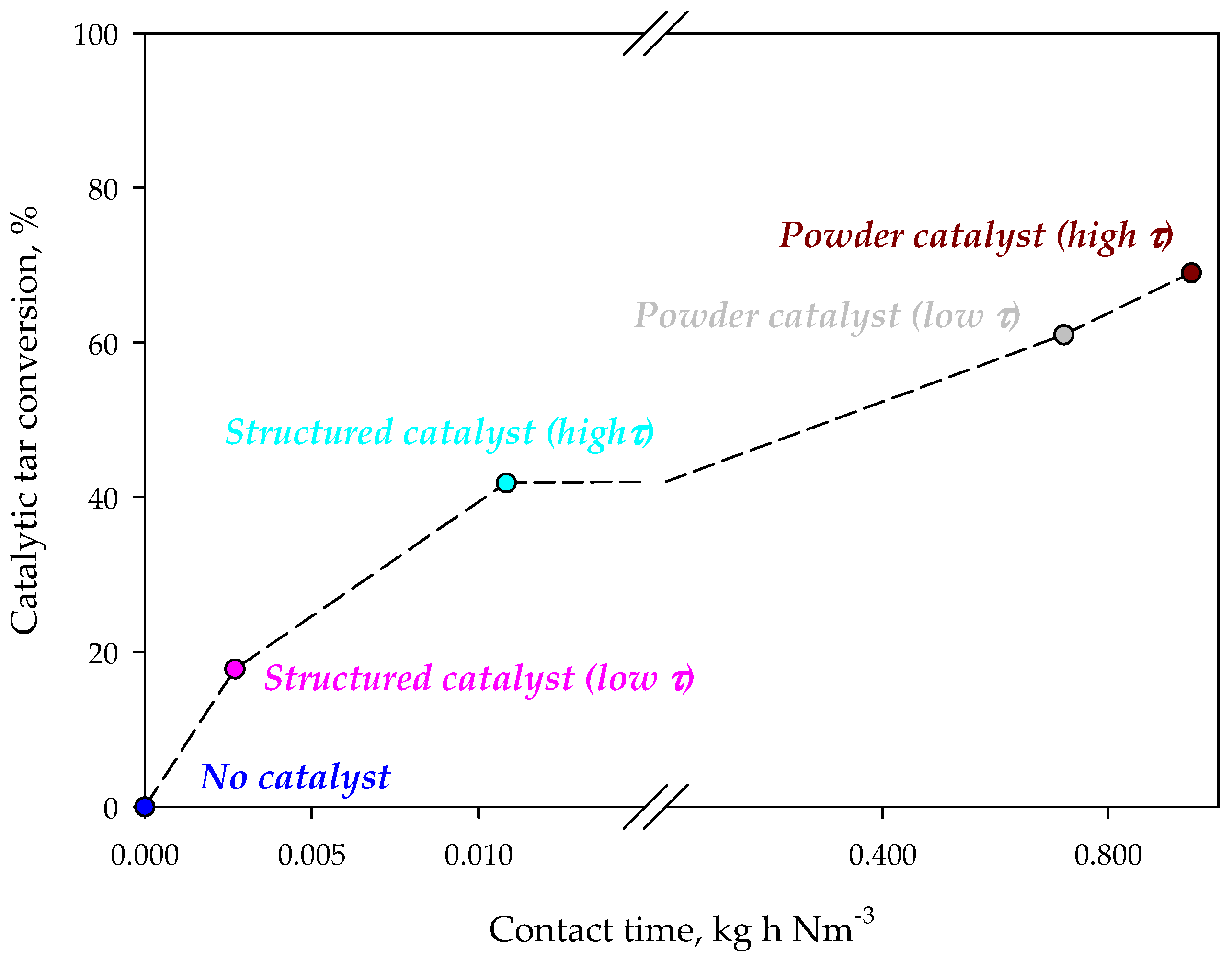
Figure 3 shows the tar concentration in the syngas for different configurations. The presence of the iron-based catalyst reduces tar concentration in the synthesis gas. On monolithic reactors the reduction of the contact time, by increasing the flow rate through the catalyst, causes a reduction of tar conversion. This result suggests that tar reaction on the catalyst is under-limited by kinetics. However, the tar abatement level is lower than that obtained in the case of using a powder catalyst, independently from the contact time. However, it should be emphasized that the amounts of catalyst and the contact times are very different for monolithic and powder catalysts. Figure 4 shows the catalytic tar conversion (i.e., the tar conversion calculated using tar concentration without catalyst as reference) as a function of the contact time; points are labelled with the corresponding configuration. Despite their lower conversions, results obtained on structured catalysts (virtually placed in the freeboard of the gasifier) are related to contact times about two orders of magnitude lower than those corresponding to powder catalysts, used within the bed of the fluidizing bed reactor. Moreover, the slope of the two straights connecting conversions related to structured and powder catalysts, respectively, are clearly very different (about 2977 vs. 25%·Nm3·kg−1·h−1). These results suggest that (i) the active phase is used more efficiently in the enhanced configuration and (ii) catalytic conversion in the configuration with powder catalyst is controlled not only by kinetic limitations, but also by an efficiency in the catalyst utilization related to the reactor fluid dynamics.
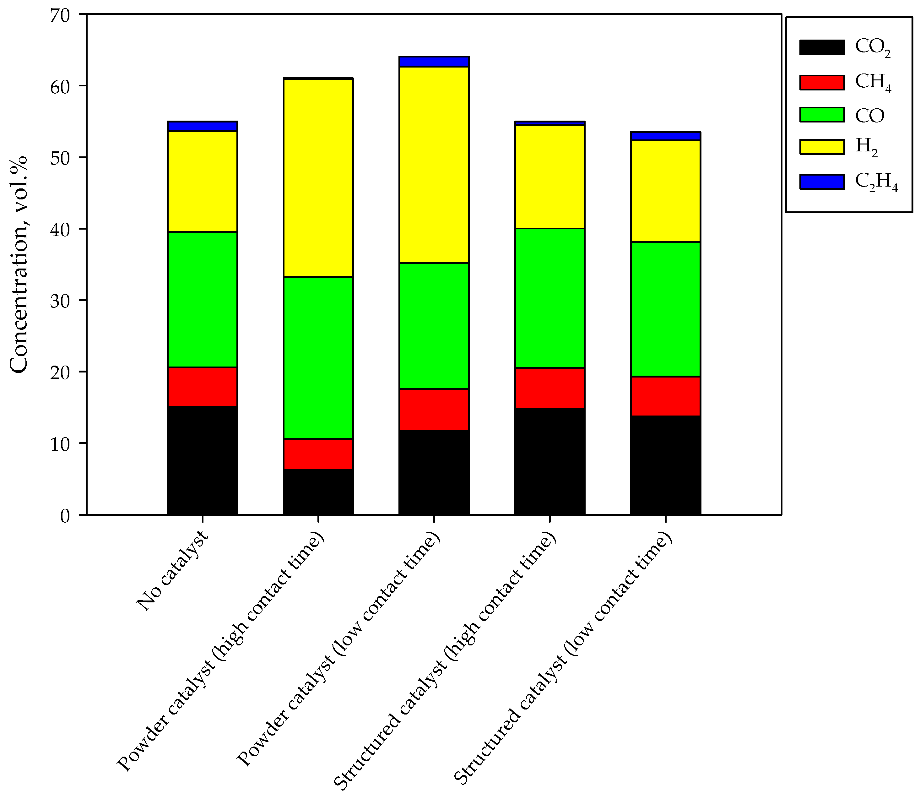
The composition of the syngas as obtained by carrying out the tests in the presence and in the absence of the catalysts (both powders and monoliths) are shown in the Figure 5 in terms of average concentrations obtained at steady state. The overall height of the bars qualitatively represents the gas production; the higher the bar, the greater the gas production. In the standard test, syngas is produced with a H2/CO ratio equal to 0.75; methane and ethylene are produced (5.5 and 1.3 vol.%, respectively), as expected [26]. A significant CO2 production is detected, mainly due to direct production by combustion reactions. Catalyst addition in the gasifier bed significantly improves both gas production and syngas selectivity. In particular, the H2/CO ratio becomes higher than 1 (1.2 and 1.6 at high and low contact time respectively). The greatest gas production is obtained at low contact time (i.e., at a higher gas flow rate); as previously reported, this is related to improved performance due to higher recirculation [26]. However, the highest syngas production is detected by increasing the contact time; in fact, the catalyst shows a non-negligible activity towards reforming and water gas shift reactions. For this reason, methane, ethylene and carbon dioxide fractions are lower.
In the presence of the monolith, the quality of the syngas is poorly modified. In particular, ethylene concentration decreases at high contact time. Accordingly, the H2/CO ratio remains about 0.75 as in the absence of catalysts. The gas production is quite unchanged too. The limited effect on the gas phase composition and production can be due to different reasons, discussed in the next session.

4. Discussion

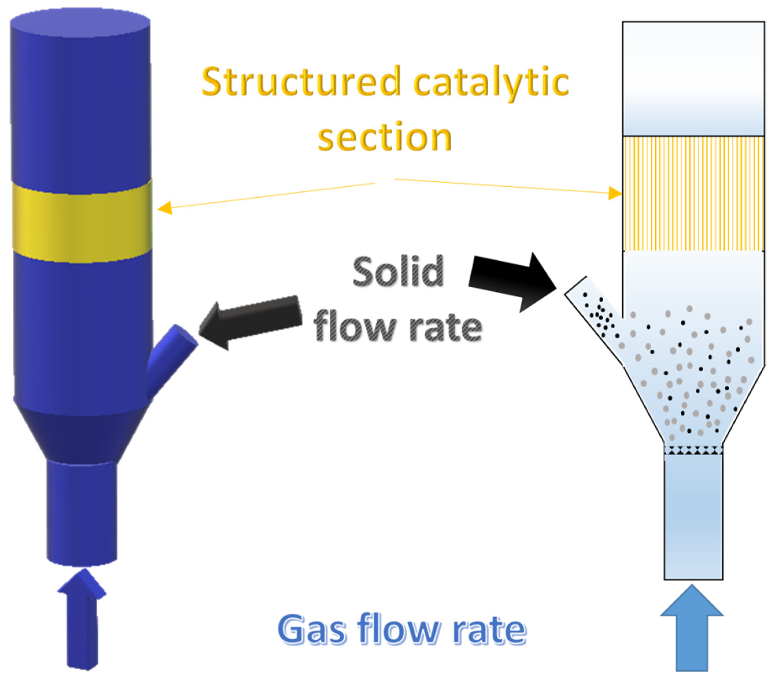
Results reported in the previous section suggest several considerations. Preliminarily, it is worth noting that we first propose a “hybrid” reactor configuration for a biomass gasifier composed by a fluidized bed and a structured catalytic reactor placed in the freeboard as sketched in Figure 6.
It has clearly been demonstrated that the use of this “hybrid” reactor configuration allows for a significant reduction in the tar concentration in the synthesis gas. The effect seems lower than that obtained by adding a powder catalyst within the bubbling bed, in terms of (i) tar conversion, (ii) gas production, and (iii) selectivity to syngas (i.e., H2 and CO production). However, the large difference among the contact times of powder and structured catalysts suggests that, in the “hybrid” configuration, the catalyst works more efficiently on tar conversion; accordingly, the low amount of catalyst to be used suggests that the process developed with the “hybrid” configurations requires lower catalyst amounts, and are thus less expensive. It is worth noting that further studies for the optimization of contact time should be carried out to optimize efficiency. Interestingly, as reported above, under the investigated operating conditions, the effect of the monolithic reactor on the syngas composition and production is negligible. This is due to the low amount of gas produced by tar conversion, negligibly affecting the gas phase composition. The improved syngas production over powder catalysts is mainly related to a more efficient gasification process (at the expense of great amounts of catalyst used). However, results obtained on the gas distribution over the powder catalyst show that the iron-based catalyst is also active towards reactions involving gas species; in this context, higher contact times and/or higher reaction temperatures can contribute to improve selectivity to H2 and CO on structured catalysts as well. The lower amount of ethylene obtained by increasing the contact time over the structured catalyst, in agreement with the behavior detected on powder catalysts, supports the above considerations.
Actually, catalytic results on tar abatement reported in the literature, independently from the process configuration used, have shown better performance than those reported in this work [5,6,16,17,18], even if a straightforward comparison is difficult, because in some cases the contact time is not reported and/or simple to calculate. However, as stated in the introduction, Ni-based catalysts have been used for tar abatement [5,6,16,17,18], iron eventually used as promoter [5,10]. On the contrary, in this work, iron was chosen as active phase, due to its lower price and lower environmental impact of its production process. Moreover, as stated above, our configuration is not yet optimized in terms of operating conditions and catalyst composition. According to these considerations, the use of a structured Fe-based catalyst in the freeboard of a biomass gasifier can potentially provide tar abatement at low cost and with a simplified thermal management.

5. Conclusions

The results achieved can be summarized by saying that the effectiveness of using a monolith for gas conditioning has been preliminarily verified. This “hybrid” configuration appears promising; in fact, a good tar conversion has been obtained under the explored operating conditions. On the contrary, the limited effect on the gas production and composition seems related to the limited range of operating conditions explored in this work rather than to the low activity of the iron-based catalyst towards reforming and water gas shift reactions.
Further optimization studies, as well as duration studies, to study the possible deactivation of the catalyst due to coke deposition must be carried out.

Supplementary Materials

The following are available online at https://www.mdpi.com/article/10.3390/fuels2040032/s1, Table S1: mean values and statistical parameters (standard deviation and error (calculated as standard deviation divided by mean value)) for each type of experiment.

Author Contributions

Conceptualization, G.R.; methodology, G.R. and G.L.; validation, G.R. and G.L.; investigation, G.R. and G.L.; resources, G.R. and G.L.; data curation, G.R. and G.L.; writing—original draft preparation, G.R. and G.L.; writing—review and editing, G.R. and G.L.; supervision, G.R. and G.L.; project administration, G.R.; funding acquisition, G.R. All authors have read and agreed to the published version of the manuscript.

Funding

The authors acknowledge the financial support of the Italian Ministry for Economic Development (MiSE) and MiSE-CNR Agreement on National Electrical System.

Data Availability Statement

The data presented in this study are available in the article.

Conflicts of Interest

The authors declare no conflict of interest.

References

  1. Abu El-Rub, Z.; Bramer, E.A.; Brem, G. Review of catalysts for tar elimination in biomass gasification processes. Ind. Eng. Chem. Res. 2004, 43, 6911–6919. [Google Scholar] [CrossRef]
  2. Simell, P.A.; Hepola, J.O.; Krause, A.O.I. Effects of gasification gas components on tar and ammonia decomposition over hot gas cleanup catalysts. Fuel 1997, 76, 1117–1127. [Google Scholar] [CrossRef]
  3. Simell, P.A.; Hirvensalo, E.K.; Smolander, V.T.; Krause, A.O.I. Steam reforming of gasification gas tar over dolomite with benzene as a model compound. Ind. Eng. Chem. Res. 1999, 38, 1250–1257. [Google Scholar] [CrossRef]
  4. Lv, P.; Chang, J.; Xiong, Z.; Huang, H.; Wu, C.; Chen, Y.; Zhu, J. Biomass air-steam gasification in a fluidized bed to produce hydrogen-rich gas. Energy Fuels 2003, 17, 677–682. [Google Scholar] [CrossRef]
  5. Liang, S.; Guo, F.; Du, S.; Tian, B.; Dong, Y.; Jia, X.; Qian, L. Synthesis of Sargassum char-supported Ni-Fe nanoparticles and its application in tar cracking during biomass pyrolysis. Fuel 2020, 275, 117923. [Google Scholar] [CrossRef]
  6. Tian, B.; Du, S.; Guo, F.; Dong, Y.; Mao, S.; Qian, L.; Liu, Q. Synthesis of biomimetic monolithic biochar-based catalysts for catalytic decomposition of biomass pyrolysis tar. Energy 2021, 222, 120002. [Google Scholar] [CrossRef]
  7. Wei, B.; Yang, H.; Hu, H.; Wang, D.; Jin, L. Enhanced production of light tar from integrated process of in-situ catalytic upgrading lignite tar and methane dry reforming over Ni/mesoporous Y. Fuel 2020, 279, 118533. [Google Scholar] [CrossRef]
  8. Lestinsky, P.; Zikmund, Z.; Grycova, B.; Ryczkowski, R.; Grams, J.; Inayat, A. Production of hydrogen over Ni/carbonaceous catalyst. Fuel 2020, 278, 118398. [Google Scholar] [CrossRef]
  9. Xu, H.; Shen, Z.; Chen, G.; Yin, C.; Liu, Y.; Ge, Z.; Wang, Y.; Zheng, Z.; Li, X. Carbon-coated mesoporous silica-supported Ni nanocomposite catalyst for efficient hydrogen production via steam reforming of toluene. Fuel 2020, 275, 118036. [Google Scholar] [CrossRef]
  10. Xie, Y.; Su, Y.; Wang, P.; Zhang, S.; Xiong, Y. In-situ catalytic conversion of tar from biomass gasification over carbon nanofibers- supported Fe-Ni bimetallic catalysts. Fuel Process. Technol. 2018, 182, 77–87. [Google Scholar] [CrossRef]
  11. Lang, L.; Zhu, H.Y.; Ding, Y.N.; Yin, X.L.; Wu, C.Z.; Yu, X.; Bridgwater, A.V. Mini-Review on Hot Gas Filtration in Biomass Gasification: Focusing on Ceramic Filter Candles. Energy Fuels 2021, 35, 11800–11819. [Google Scholar] [CrossRef]
  12. Toledo, J.M.; Corella, J.; Molina, G. Catalytic hot gas cleaning with monoliths in biomass gasification in fluidized beds. 4. Performance of an advanced, second-generation, two-layers-based monolithic reactor. Ind. Eng. Chem. Res. 2006, 45, 1389–1396. [Google Scholar] [CrossRef]
  13. Heidenreich, S. Hot gas filtration—A review. Fuel 2013, 104, 83–94. [Google Scholar] [CrossRef]
  14. Heidenreich, S.; Foscolo, P.U. New concepts in biomass gasification. Prog. Energy Combust. Sci. 2015, 46, 72–95. [Google Scholar] [CrossRef]
  15. Heidenreich, S.; Nacken, M.; Foscolo, P.U.; Rapagna, S. Gasification Apparatus and Method for Generating Syngas from Gasifiable Feedstock Material. US Patent 20100223848 A1, 9 September 2010. [Google Scholar]
  16. Rapagnà, S.; Gallucci, K.; di Marcello, M.; Matt, M.; Nacken, M.; Heidenreich, S.; Foscolo, P.U. Gas cleaning, gas conditioning and tar abatement by means of a catalytic filter candle in a biomass fluidized-bed gasifier. Bioresour. Technol. 2010, 101, 7123–7130. [Google Scholar] [CrossRef] [PubMed]
  17. Nacken, M.; Ma, L.; Heidenreich, S.; Baron, G.V. Catalytic activity in naphthalene reforming of two types of catalytic filters for hot gas cleaning of biomass-derived syngas. Ind. Eng. Chem. Res. 2010, 49, 5536–5542. [Google Scholar] [CrossRef]
  18. de Diego, L.F.; García-Labiano, F.; Gayán, P.; Abad, A.; Mendiara, T.; Adánez, J.; Nacken, M.; Heidenreich, S. Tar abatement for clean syngas production during biomass gasification in a dual fluidized bed. Fuel Process. Technol. 2016, 152, 116–123. [Google Scholar] [CrossRef]
  19. Savuto, E.; Di Carlo, A.; Steele, A.; Heidenreich, S.; Gallucci, K.; Rapagnà, S. Syngas conditioning by ceramic filter candles filled with catalyst pellets and placed inside the freeboard of a fluidized bed steam gasifier. Fuel Process. Technol. 2019, 191, 44–53. [Google Scholar] [CrossRef]
  20. Simell, P.; Kurkela, E.; Ståhlberg, P.; Hepola, J. Catalytic hot gas cleaning of gasification gas. Catal. Today 1996, 27, 55–62. [Google Scholar] [CrossRef]
  21. Pfeifer, C.; Hofbauer, H. Development of catalytic tar decomposition downstream from a dual fluidized bed biomass steam gasifier. Powder Technol. 2008, 180, 9–16. [Google Scholar] [CrossRef]
  22. Thompson, C.R.; Marín, P.; Díez, F.V.; Ordóñez, S. Evaluation of the use of ceramic foams as catalyst supports for reverse-flow combustors. Chem. Eng. J. 2013, 221, 44–54. [Google Scholar] [CrossRef] [Green Version]
  23. Li, X.; Dai, H.; Deng, J.; Liu, Y.; Xie, S.; Zhao, Z.; Wang, Y.; Guo, G.; Arandiyan, H. Au/3DOM LaCoO3: High-performance catalysts for the oxidation of carbon monoxide and toluene. Chem. Eng. J. 2013, 228, 965–975. [Google Scholar] [CrossRef]
  24. Cocchi, S.; Nutini, G.; Spencer, M.J.; Nickolas, S.G. Catalytic combustion system for a 10 MW class power generation gas turbine. Catal. Today 2006, 117, 419–426. [Google Scholar] [CrossRef]
  25. Furuya, T.; Sasaki, K.; Hanakata, Y.; Ohhashi, T.; Yamada, M.; Tsuchiya, T.; Furuse, Y. Development of a hybrid catalytic combustor for a 1300 °C class gas turbine. Catal. Today 1995, 26, 345–350. [Google Scholar] [CrossRef]
  26. Miccio, F.; Picarelli, A.; Ruoppolo, G. Increasing tar and hydrocarbons conversion by catalysis in bubbling fluidized bed gasifiers. Fuel Process. Technol. 2016, 141, 31–37. [Google Scholar] [CrossRef]
  27. Bareschino, P.; Mancusi, E.; Tregambi, C.; Pepe, F.; Urciuolo, M.; Brachi, P.; Ruoppolo, G. Integration of biomasses gasification and renewable-energies-driven water electrolysis for methane production. Energy 2021, 230, 120863. [Google Scholar] [CrossRef]
  28. Miccio, F.; Piriou, B.; Ruoppolo, G.; Chirone, R. Biomass gasification in a catalytic fluidized reactor with beds of different materials. Chem. Eng. J. 2009, 154, 369–374. [Google Scholar] [CrossRef]
  29. Barbato, P.S.; Di Benedetto, A.; Di Sarli, V.; Landi, G.; Pirone, R. High-pressure methane combustion over a perovskyte catalyst. Ind. Eng. Chem. Res. 2012, 51, 7547–7558. [Google Scholar] [CrossRef]
  30. Landi, G.; Barbato, P.S.; Di Sarli, V.; Di Benedetto, A. Multifuel catalytic combustion in the presence of carbon dioxide over fully and partially perovskite-coated monoliths. Ind. Eng. Chem. Res. 2017, 56, 4920–4928. [Google Scholar] [CrossRef] [Green Version]
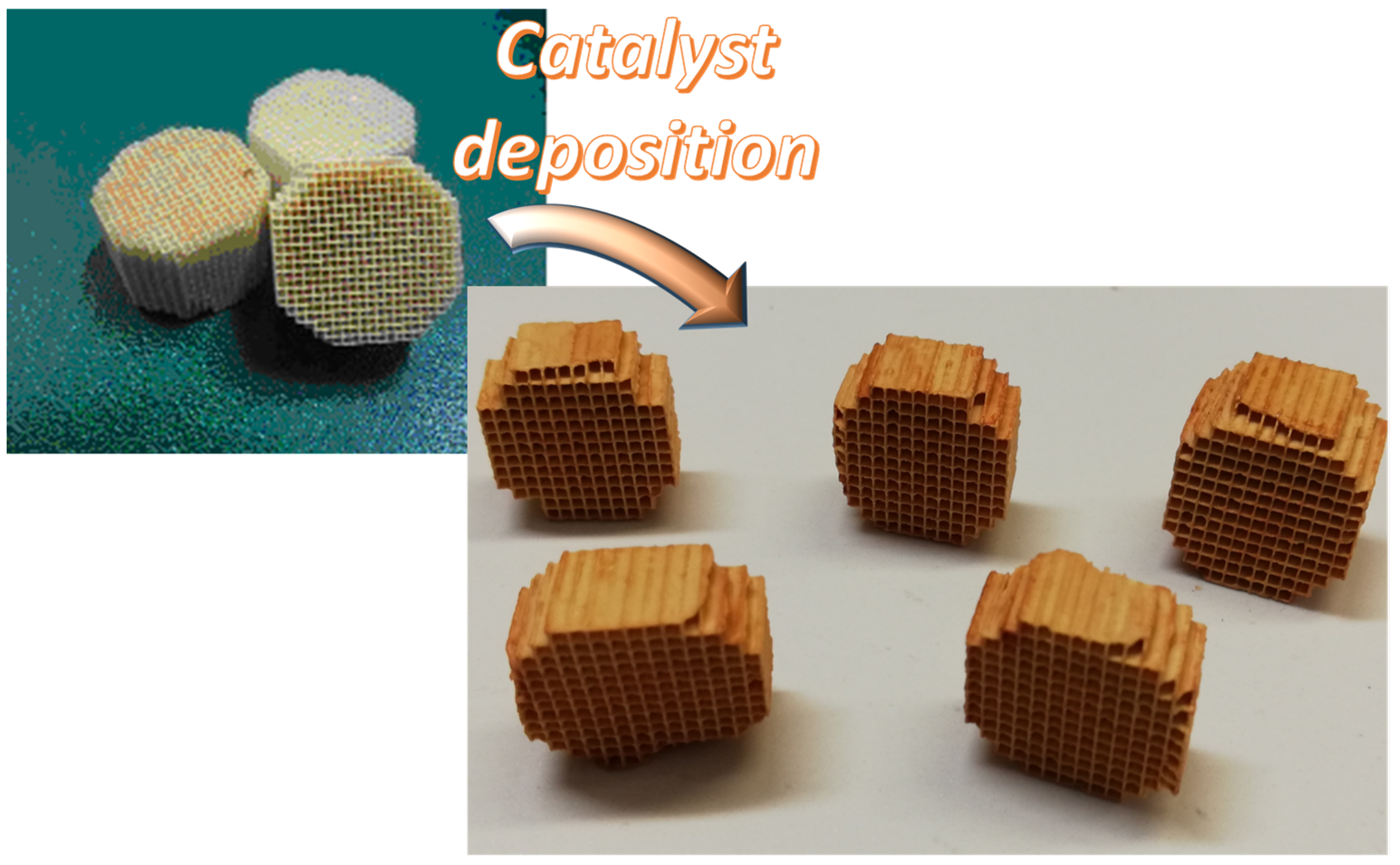
Figure 1. Picture of blank and prepared monoliths.
Fuels 02 00032 g001
Figure 2. Schematic representation of the quartz reactor containing the structured catalysts.
Fuels 02 00032 g002
Figure 3. Tar concentration in the synthesis gas during standard and enhanced gasification tests.
Fuels 02 00032 g003
Figure 4. Catalytic tar conversion as a function of the contact time during standard and enhanced gasification tests.
Fuels 02 00032 g004
Figure 5. Gas composition during standard and enhanced gasification tests.
Fuels 02 00032 g005
Figure 6. Sketch of the “hybrid” fluidized bed gasifier enhanced by a structured catalyst placed in the freeboard.
Fuels 02 00032 g006
Table 1. Spruce wood pellet characterization and experimental conditions used for both standard and enhanced gasification tests.
ParameterValue
Pellet characterization
Pellets size (mm)6 × 20
Proximate analysis (wt%, as received basis)
Moisture 8.4
Volatiles 74.2
Fixed carbon 17.1
Ash 0.3
Ultimate analysis (wt%, dry basis)
Carbon 49.3
Hydrogen 5.90
Nitrogen 0.10
Oxygen 44.7
Operative conditions
ER0.15
Bed height (cm)18–26
Bed materialQuartzite or Fe/Al2O3 catalyst
Operating temperature (°C)830
Effective velocity (m/s)0.17–0.3
Publisher’s Note: MDPI stays neutral with regard to jurisdictional claims in published maps and institutional affiliations.