Abstract
In recent years, protecting stainless steel from corrosion has become crucial, particularly in harsh environments. The present study focuses on improving the photocathodic corrosion resistance of 304 stainless steel (304SS) by fabricating TiO2/CuO composite coatings using the spin coating technique with varying CuO weight percentages. Structural characterization through X-ray diffraction (XRD) confirmed the presence of the anatase phase of TiO2 and the successful integration of CuO. Raman spectroscopy demonstrated redshifts in the TiO2 characteristic peaks, suggesting changes in bond lengths attributed to CuO incorporation. These findings were further corroborated by Fourier-transform infrared (FTIR) spectroscopy. Surface characterization showed uniform, porous coatings with pore sizes ranging from 75 to 200 nm, which contributed to improved barrier properties. UV–visible diffuse reflectance spectroscopy (UV-DRS) demonstrated enhanced visible light absorption in the heterostructures. Mott–Schottky analysis confirmed improved charge carrier density and favorable band alignment, facilitating efficient charge separation. The electrochemical performance was evaluated in 3.5% NaCl solution under dark and light environments. The results demonstrated that the TiO2/CuO heterostructure significantly enhanced electron transfer and suppressed electron-hole recombination, providing adequate photocathodic protection. Notably, under illumination, the TiO2/CuO (0.005 g) coating achieved a corrosion potential of −255 mV vs SCE and reduced the corrosion current density to 0.460 × 10⁻⁶ mA cm−2. These findings suggest that TiO2/CuO coatings offer a promising, durable, and cost-effective solution for corrosion protection in industries such as oil, shipbuilding, and pipelines.
1. Introduction
Corrosion of stainless steel, particularly 304SS, has garnered significant attention due to its widespread use. Its versatility makes it ideal for applications ranging from offshore appliances and shipbuilding to household items like refrigerators and sinks and industrial uses such as piping and machinery. 304 stainless steel (304SS) is commonly utilized in offshore applications due to its superior corrosion resistance and ease of fabrication [1]. Despite these advantages, it remains susceptible to localized corrosion, such as pitting and crevice corrosion, particularly in marine environments or chloride-rich solutions. This degradation occurs when chloride ions penetrate and disrupt the passive oxide film on the steel surface, resulting in the initiation of pits that can significantly compromise the structural integrity of the material [2,3].
Several strategies have been employed to address this, such as anodizing, applying protective coatings, and surface treatments [4]. Recently, the photocathodic corrosion protection technique has emerged as an effective method to prevent the material from chloride ion incursion. The photocathodic protection for metals has gained increasing attention as a promising and environmentally friendly technology [5,6,7]. This method leverages the ability of certain semiconductor materials to generate photoelectrons when exposed to light, providing additional protection against corrosion [8]. A significant challenge in photocathodic corrosion protection is identifying suitable photoactive semiconductors that can withstand long-term environmental conditions.
Yuan and Tsujikawa initially demonstrated TiO2 as a photoanode for corrosion protection in 1995, where it successfully protected copper surfaces [9]. Since then, TiO2 has become a prominent material in photocathodic corrosion protection applications. Over the past 30 years, extensive research has focused on employing various semiconductors—such as TiO2, SrTiO3, In2O3, and ZnO—for the photocathodic protection of metals [6,9,10,11,12,13,14,15]. Among these, TiO2 is the most widely utilized, owing to its exceptional photoelectrocatalytic behavior, excellent chemical stability, strong oxidative capability, and environmental friendliness. These characteristics make TiO2 an ideal material for corrosion prevention, particularly in seawater or chloride-rich solution applications, where corrosion is a significant concern [16,17,18,19,20,21,22,23,24].
However, TiO2 is limited by its wide band gap, which confines its light absorption primarily to the ultraviolet region and its quick charge recombination rate [25,26]. Researchers have explored various modifications to TiO2 to improve its photocatalytic activity and corrosion resistance, further advancing the field of photocathodic protection. To improve the photocatalytic efficiency of TiO2, extensive research has focused on strategies such as doping and combining it with narrow-bandgap semiconductors. Materials like ZnSe, CdS, WO3, graphene, Mn-Cr, Ag2S, Zn3In2S, α-Fe2O3, and V2O5 have been explored for this purpose [27,28,29,30,31,32,33,34,35].
Among these, copper oxide (CuO), with a relatively narrow band gap of approximately 1.8 eV [36], is particularly attractive due to its strong absorption in the visible light region and its frequent use in photocatalytic applications. As a p-type semiconductor, CuO can establish a built-in electric field at the interface when paired with an n-type semiconductor, facilitating charge separation and enhancing photocatalytic activity. This p-n heterostructure accelerates the directional movement of photo-generated electrons and holes, enhancing charge carrier separation and improving photocathodic corrosion protection [37,38]. However, the TiO2/CuO heterostructure has been extensively explored in fields such as photocatalytic organic pollutant degradation, CO2 reduction, and hydrogen production [39,40,41,42]. Despite this extensive exploration, their use in photocathodic corrosion protection remains largely unaddressed. Most of the available literature focuses on the photocatalytic performance of these materials, with limited reports detailing their application as protective coatings for metallic substrates. Therefore, integrating CuO with TiO2 in a heterostructure presents substantial potential for developing advanced materials that effectively overcome the individual limitations of CuO and TiO2 [43,44,45]. The utility of TiO2/CuO systems extends beyond traditional photocatalysis and introduces a new pathway for sustainable corrosion protection of metals under illumination.
This study synthesized a TiO2/CuO heterostructure coating and applied it onto 304 stainless steel (304SS) substrates via spin coating to enhance photocathodic protection under visible light irradiation. The structural and chemical features of the coatings were analyzed using X-ray diffraction (XRD), Raman spectroscopy, and Fourier-transform infrared spectroscopy (FTIR). Additionally, the optical properties and bandgap energies were evaluated using UV–Vis diffuse reflectance spectroscopy (UV–Vis DRS), and the semiconductor behavior and flat-band potentials were assessed through Mott–Schottky analysis. Morphological and elemental analyses were conducted using scanning electron microscopy (SEM), energy-dispersive X-ray spectroscopy (EDX), and atomic force microscopy (AFM). Electrochemical techniques systematically evaluated the photocathodic protection performance, including open-circuit potential (OCP), potentiodynamic polarization, and photocurrent measurements under illumination. This combination of analytical and electrochemical techniques enabled a comprehensive evaluation of the corrosion protection capability of the TiO2/CuO heterostructure. Investigating TiO2/CuO heterojunctions for photocathodic corrosion protection provides deeper insights into recent advancements in TiO2/CuO heterostructures and strategies for optimizing their design. Employing TiO2/CuO heterostructures as photoanodes significantly improves photocathodic corrosion protection by promoting efficient separation of photo-generated charge carriers and facilitating electron transport to the metal surface.
2. Materials and Methods
2.1. Materials
Titanium tetraisopropoxide (Ti(OCH(CH3)2)4), n-butanol (BuOH), and copper nitrate (Cu(NO3)2·3H2O) were sourced from Sigma-Aldrich. All reagents and chemicals used in the synthesis process were of analytical grade and utilized without additional purification. Deionized water was employed in all experimental procedures.
The chemical composition of 304 stainless steel (304SS) is summarized in Table 1. The 304SS substrates were cut into rectangular pieces with dimensions of 10 mm × 20 mm × 2 mm for coating and electrochemical analysis. The substrate was polished using silicon carbide abrasive paper of varying grit sizes to remove surface imperfections and achieve a smooth finish. Coarser grits (e.g., 80 or 120 grit) were initially used to eliminate visible surface defects, such as scratches or uneven areas. Finer grits (e.g., 400, 800, 1000, and 2000 grit) were employed, followed by diamond paste and aerosol polish for further refinement. This thorough polishing process resulted in a scratch-free, mirror-like finish on the 304SS substrate, providing an optimal surface for subsequent treatments. After polishing, the substrate was thoroughly rinsed with distilled water, cleaned with acetone, and washed with ethanol.

Table 1.
Weight percentage composition of the 304SS stainless steel alloy (304SS).
2.2. Synthesis of TiO2/CuO Heterostructure
Titanium tetraisopropoxide (TTIP) was used as the metal oxide precursor, and n-butanol served as the solvent in a 2:8 ratio to synthesize TiO2 via the sol–gel method [46,47]. The TiO2 sol was prepared by stirring the mixture for 2 h. The TiO2/CuO heterostructure was synthesized using a simple chemical reduction method [48,49]. Specifically, different amounts of copper nitrate (Cu(NO3)2), such as 0.001 g, 0.005 g, 0.01 g, and 0.05 g, were dissolved in methanol to form a CuO solution. Then, the CuO solution was slowly added to the as-prepared TiO2 sol. The mixture was stirred for 30 min to allow uniform dispersion and interaction. Subsequently, the resulting solution was ultrasonicated for 1 h to ensure homogeneous mixing and to facilitate heterostructure formation.
2.3. Fabrication of TiO2/CuO Heterostructure Coating on 304SS Alloy
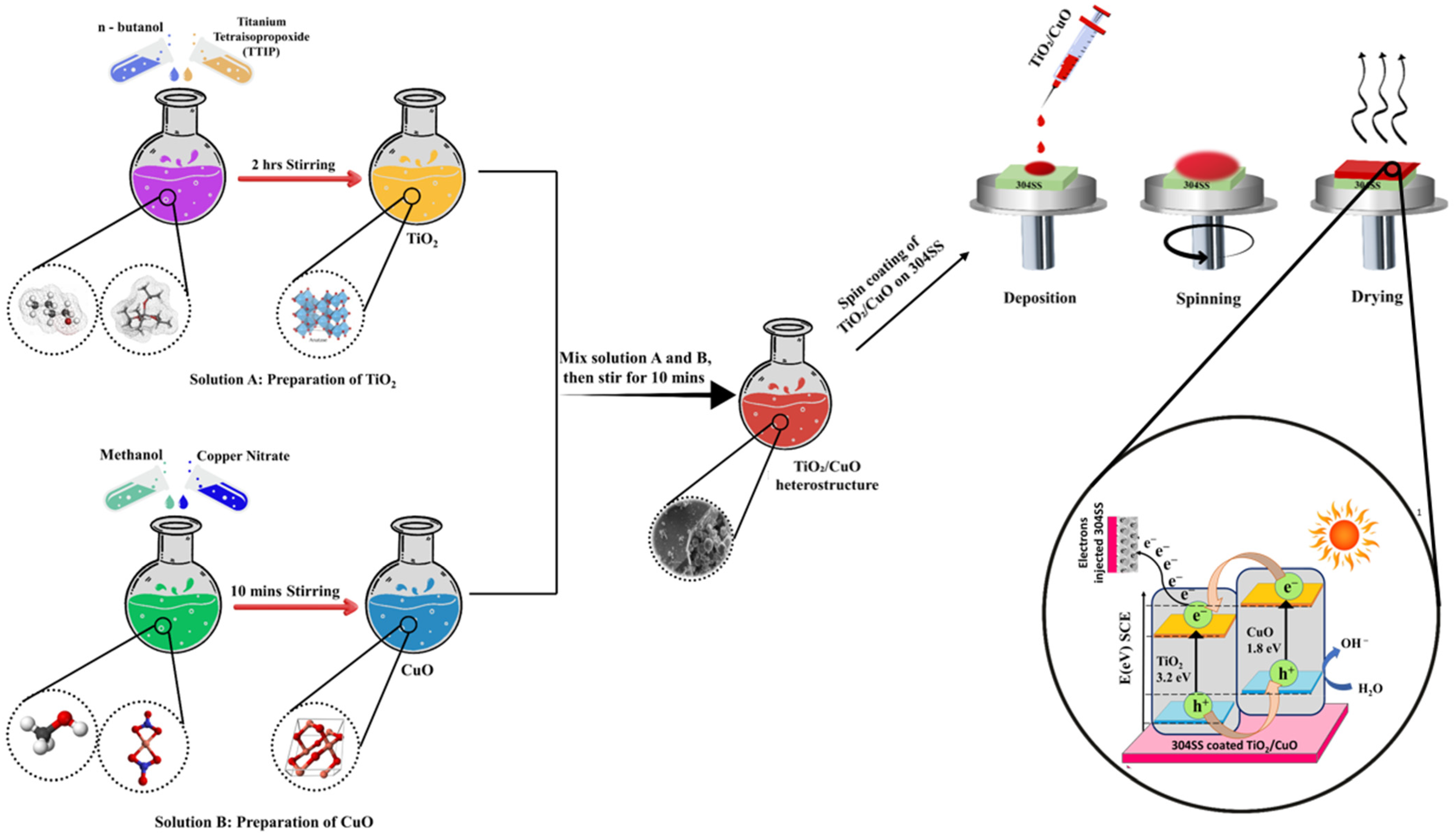
The TiO2/CuO heterostructure coatings were prepared using a spin-coating method (Apex Instrument, Kolkata, India). A TiO2/CuO sol was spin-coated onto 304SS substrates, then sintered at 150 °C to form the initial layer. The coatings were designated as TiO2/CuO (0.001), TiO2/CuO (0.005), TiO2/CuO (0.01), and TiO2/CuO (0.05), based on the respective CuO concentrations incorporated in a 10 mL solution: 1 mg, 5 mg, 10 mg, and 50 mg, respectively. While variations in CuO content influenced corrosion resistance, electrochemical performance, and stability, the overall coating thickness remained unchanged. Multiple spin-coating cycles were performed using the TiO2/CuO (0.005) sol to examine the effect of coating thickness. A single deposition corresponded to one layer, while two, three, and four consecutive depositions resulted in coatings with additional layers. The resulting coated substrates were sintered at 450 °C in a muffle furnace (Indfurr Superheat Furnaces, Chennai, India) before undergoing electrochemical studies to evaluate their performance. The primary objective was to determine the optimal CuO concentration for enhancing the corrosion resistance and electrochemical stability of the TiO2/CuO coatings and assess the impact of coating thickness on these properties. A schematic illustration of the TiO2/CuO heterostructure synthesis and coating process is presented in Figure 1.
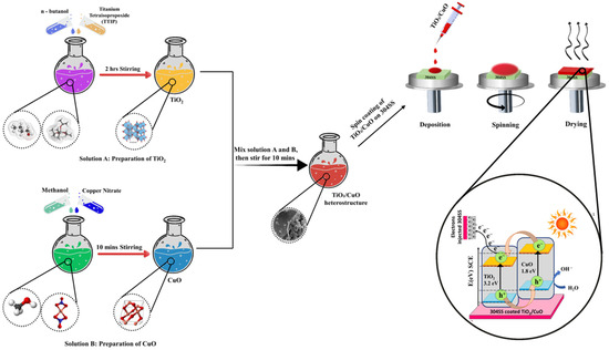
Figure 1.
Schematic illustration of the formation process of the TiO2/CuO heterostructure.
2.4. Characterization
Characterization of the samples was performed using various analytical techniques. Raman spectra were collected at room temperature using an optical microscope equipped with a WITec Raman spectrophotometer (WITec GmbH, Baden-Wurttemberg, Germany). The instrument was calibrated with a Si(100) standard at a wavelength of 532 nm before spectral acquisition. The chemical bonding characteristics of the TiO2/CuO heterostructures were examined using Fourier-transform infrared (FTIR) spectroscopy in attenuated total reflectance (ATR) mode, employing a JASCO 6800-FV-BB spectrometer (JASCO Corporation, Tokyo, Japan). Surface topography was analyzed using atomic force microscopy (AFM) on an Asylum Research MFP-3D Origin AFM (Oxford Instruments, Abingdon, UK) operated in tapping mode. Silicon nitride cantilevers with a spring constant of 0.15 N/m and a resonance frequency of 300 kHz were used for imaging, which was conducted under ambient conditions at room temperature. The surface morphology of the coatings was further observed using scanning electron microscopy (SEM) with a Carl Zeiss instrument (Oberkochen, Germany) operated at an accelerating voltage of 10 kV. The electrochemical performance was evaluated using an Origaflex OGF05A electrochemical workstation (Origalys Electrochem SAS, Rillieux-la-Pape, France) in a standard three-electrode configuration. Photocathodic protection behavior was studied using a 150 W Xenon Short Arc Lamp integrated into the SS50AAA-TP/EM Solar Simulator (Moorpark, California, United States) (Class AAA, ASTM E927-2010 [47], IEC 60904 9 Ed. 2.0), equipped with an AM1.5G filter. The illuminated area was 50 mm × 50 mm, with a calibrated light intensity of 100 mW/cm2 (1 sun). The AM1.5G filter ensured a spectral range of 300–800 nm, simulating natural sunlight under global tilt conditions. Open circuit potential (OCP) measurements were carried out in 3.5 wt% NaCl solution, using the coated 304SS electrode (1 cm2 exposed surface area) as the working electrode, a saturated calomel electrode (SCE) as the reference, and a platinum foil as the counter electrode. OCP was monitored under dark and illuminated conditions for 30 min to ensure stabilization. After achieving a stable potential, electrochemical impedance spectroscopy (EIS) was performed over a frequency range of 100 kHz to 10 mHz with a 10 mV AC amplitude, lasting approximately 7–15 min. Potentiodynamic polarization (Tafel) measurements were then conducted by scanning the potential from −250 mV to +250 mV versus OCP at a scan rate of 1 mV/s, each taking 10–20 min. Finally, chronoamperometry was performed at a fixed potential of 0.2 V under alternating light and dark conditions, with 300 s intervals per cycle, for 30 min to assess the photocurrent response and stability. All electrochemical tests were repeated three times to confirm the reproducibility of the results.
3. Results
3.1. Raman Analysis
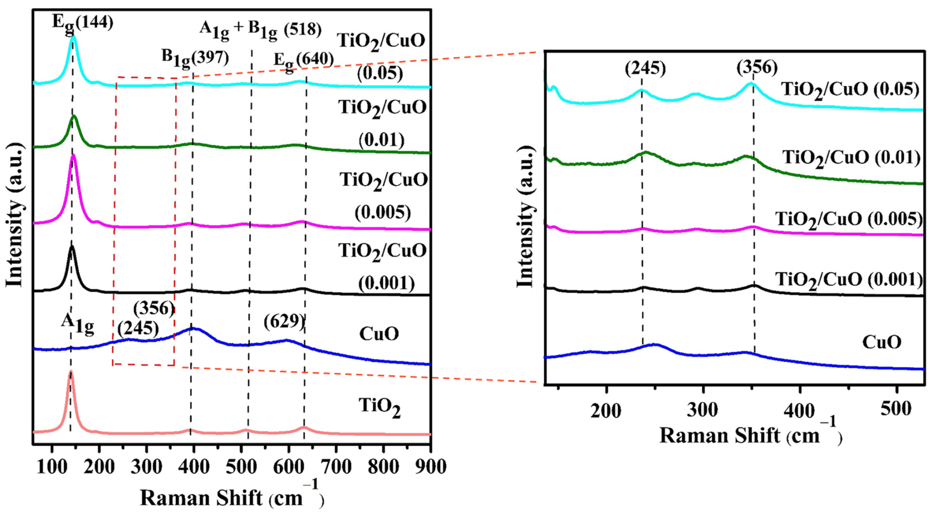
The Raman spectra revealed surface modifications induced by vibrational modes, and the analysis was performed to demonstrate the phases and impurities detected in the TiO2/CuO heterostructure. Figure 2 shows strong Raman signals within the 140 to 800 cm−1 range, which is commonly used to identify heterostructures. For anatase TiO2, six distinctive Raman-active modes were observed at 144 cm−1 (Eg), 197 cm−1 (Eg), 397 cm−1 (B1g), 518 cm−1 (A1g + B1g), and 640 cm−1 (Eg), substantiating the presence of the anatase TiO2 phase [48,49]. In the TiO2 Raman spectrum, the active vibrational modes included (i) symmetric vibration of O–Ti–O, corresponding to the doubly degenerate Eg modes at 144 and 640 cm−1, and (ii) symmetric bending vibration of O–Ti–O, associated with the B1g mode at 397 cm−1. Additionally, the Ag peak at 245 cm−1, attributed to CuO, further confirmed the presence of anatase TiO2-specific peaks, as reported in the literature [50,51]. The CuO caused shifts in the Raman peaks associated with the B1g and A1g vibration modes, confirming the structural phases of TiO2 and CuO in the TiO2/CuO heterostructure. The incorporation of CuO altered the structural and vibrational features of the TiO2 lattice, suggesting significant interaction between the two oxides. Such interactions are likely to generate surface defects that may function as photoactive sites, thereby improving charge separation efficiency [52]. As observed, the Raman spectrum of CuO at 245, 356, and 582 cm−1 corresponded to Ag and Bg modes, respectively [53]. However, in the TiO2/CuO heterostructure analysis, CuO-related signals were not prominently detected, likely due to signal suppression by the stronger TiO2 peaks. This was ascribed to the enhanced crystallinity or greater abundance of TiO2 within the heterostructure. The absence of detectable CuO peaks further supported the successful formation of the TiO2/CuO heterostructure. Similar peaks were observed across the heterostructures with different CuO weight percentages, confirming the consistent presence of anatase TiO2 crystallites. At lower CuO contents, CuO-related signals were more challenging to detect due to the dominant Raman response of TiO2, which highlighted the successful integration of CuO into the heterostructure [54].

Figure 2.
Raman spectra of TiO2, CuO, and TiO2/CuO heterostructures with varying CuO content (0.001, 0.005, 0.01, and 0.05 weight percent) coated on 304 stainless steel (304SS). The spectra show characteristic vibrational modes of anatase TiO2 and monoclinic CuO, confirming successful heterojunction formation. The inset displays a magnified view of the 245 cm−1 and 356 cm−1 regions, highlighting the evolution of CuO-specific peaks with increasing CuO content. The red dashed line indicates the region highlighted in the magnified inset.
Additionally, a slight red shift was recorded in the Raman peaks of the TiO2/CuO heterostructure compared to pure TiO2. Specifically, the Eg mode of TiO2 shifted from 144 cm−1 to 151 cm−1, indicating the formation of the TiO2/CuO heterostructure [49]. A magnified view of the 245 cm−1 and 356 cm−1 regions reveals more distinctly the evolution of CuO-related vibrational modes. These regions were carefully analyzed to examine the acceptable structural variations induced by the incorporation of CuO at varying concentrations. The shift and broadening of these peaks with increasing CuO content suggest enhanced coupling effects and phonon confinement within the heterostructure, which may be crucial in improving photocathodic performance.
3.2. Fourier Transformer Infrared Spectroscopy
The FTIR spectra of TiO2, CuO, and TiO2/CuO heterostructures with varying CuO concentrations (TiO2/CuO (0.001), TiO2/CuO (0.005), TiO2/CuO (0.01), and TiO2/CuO (0.05)) coated on 304SS are presented in Figure 3. A broad peak between 3500 and 3400 cm−1, visible in Figure 3, arises due to the O-H stretching mode of H2O, indicating the presence of surface-adsorbed water and hydroxyl groups on the surface of pure CuO and TiO2. Additionally, a peak near 1600 cm−1, attributed to the O-H bending mode of water, appears in the spectra of these pure samples [55,56]. A prominent band below 1000 cm−1, observed at 663.51 cm−1, corresponds to the metal–oxygen (M-O) bond, signifying both Cu–O and Ti–O bonds. This strong absorption band confirms effective chemical interactions between CuO and TiO2 in the heterostructures, contributing to enhanced charge transfer and stability, which are essential for photocathodic protection. The spectra show that the region between 1000 and 400 cm−1 displays peaks associated with the symmetric stretching of the Cu–O and Ti–O bonds. Increasing CuO concentration in the heterostructures gradually decreases the peak intensities, indicating robust interactions between CuO and TiO2. These findings confirm the successful formation of TiO2/CuO heterostructures on 304SS, which are expected to enhance photocathodic protection efficiency by facilitating electron transfer and corrosion resistance [57,58].
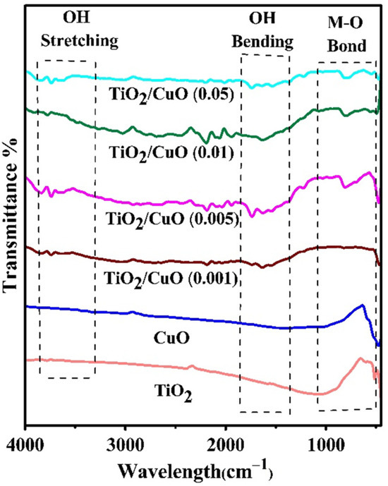
Figure 3.
IR spectra of TiO2, CuO, and TiO2/CuO heterostructures with varying CuO content (0.001, 0.005, 0.01, and 0.05 weight percent) coated on 304 stainless steel (304SS).
3.3. UV–vis-Diffusion Reflectance Spectra
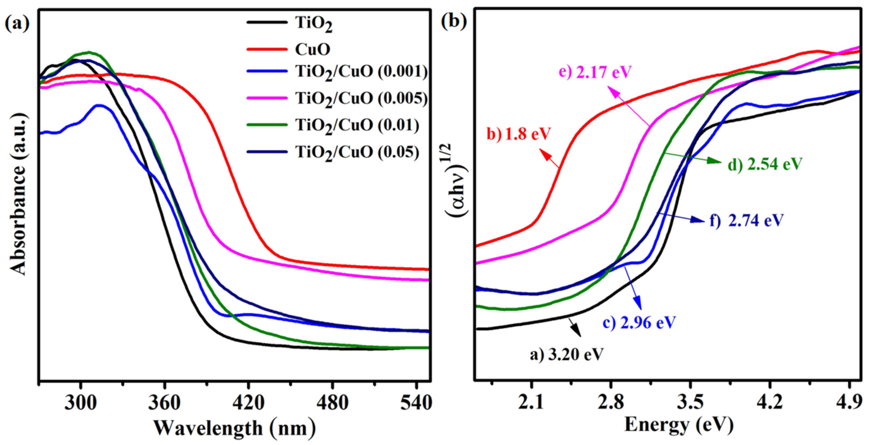
The UV–vis diffuse reflectance spectra (UV–vis DRS) of TiO2, CuO, and TiO2/CuO heterostructures with varying CuO content (0.001, 0.005, 0.01, and 0.05 wt%) are shown in Figure 4a. Pure TiO2 exhibits strong absorption in the UV region but limited absorption in the visible range, reflecting its wide band gap and restricted activity under visible light [36]. In contrast, CuO displays significant absorption in the visible region due to its narrow band gap (~1.8 eV), indicating its potential for enhanced solar light utilization [25]. The TiO2/CuO heterostructures exhibit a noticeable redshift in the absorption edge and a broadened visible light response compared to pristine TiO2. This shift confirms the formation of heterojunctions between TiO2 and CuO, facilitating improved light harvesting and charge separation efficiency. The Tauc plots (Figure 4b) estimated the optical band gaps using the transformed Kubelka–Munk function [59]. The band gaps were calculated to be approximately 3.20 eV (a, TiO2), 1.80 eV (b, CuO), 2.96 eV (c, TiO2/CuO–0.001), 2.17 eV (d, TiO2/CuO–0.005), 2.54 eV (e, TiO2/CuO–0.01), and 2.74 eV (f, TiO2/CuO–0.05). These results indicate that the TiO2/CuO heterostructures possess band gap values intermediate between those of TiO2 and CuO, with the (0.005) CuO composite exhibiting the most significant narrowing [60]. The reported band gaps were experimentally determined by UV–Vis DRS and may vary slightly due to microstructural effects and defect states in the coatings. This suggests an enhanced ability to absorb visible light and implies improved photoelectrochemical performance under solar irradiation.
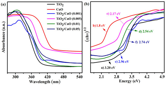
Figure 4.
(a) UV–vis diffuse reflectance spectra (UV–vis DRS) of the as-prepared samples: TiO2, CuO, and TiO2/CuO heterostructures with varying CuO content (0.001, 0.005, 0.01, and 0.05 wt%). (b) Tauc plots derived from the transformed Kubelka–Munk function versus photon energy (hν) for determining the optical band gaps of (a) TiO2, (b) CuO, (c) TiO2/CuO (0.001), (d) TiO2/CuO (0.005), (e) TiO2/CuO (0.01), and (f) TiO2/CuO (0.05).
3.4. Scanning Electron Microscopy
The surface morphology of uncoated 304SS and TiO2, CuO, and TiO2/CuO (0.005) coated 304SS substrates was examined via SEM, as depicted in Figure 5. The SEM image of bare 304SS (Figure 5a) reveals grid-like marks resulting from mechanical polishing, indicating a smooth baseline surface with minimal microstructural irregularities at both magnifications [38]. In contrast, the TiO2-coated 304SS (Figure 5b) appears as a uniform layer at lower magnification. However, at higher magnification, the surface reveals nearly spherical, agglomerated particles forming a microporous structure. This morphology increases surface area and promotes electrolyte interaction, while the uniform coverage suggests strong adhesion and adequate surface protection, making it suitable for catalytic and protective applications.
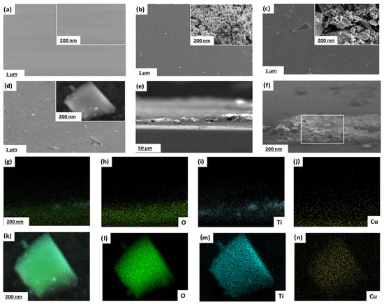
Figure 5.
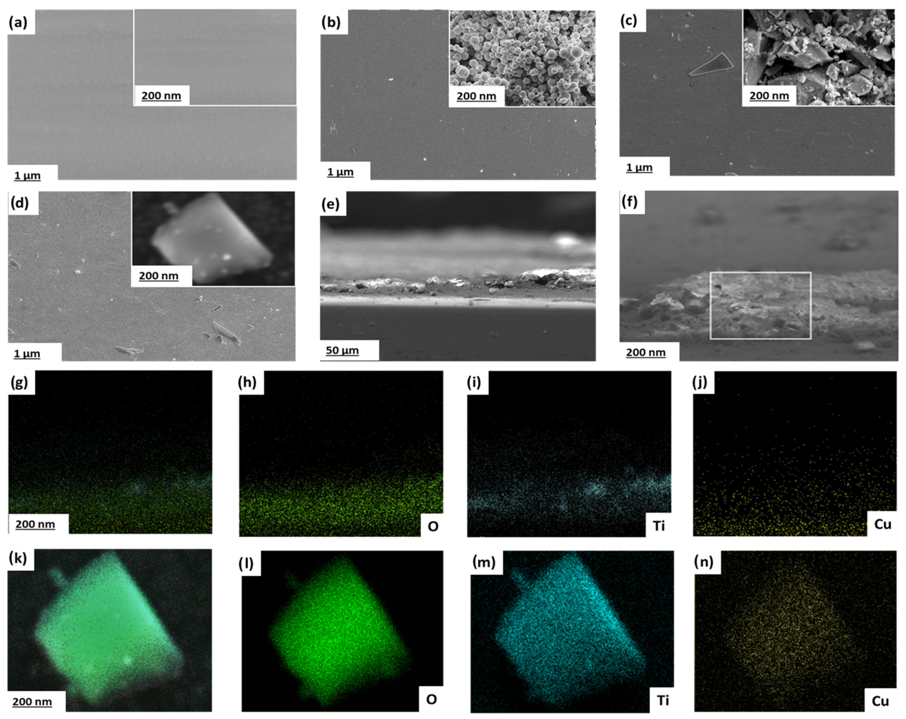
Scanning electron micrographs of (a–d) images (with insets showing higher magnifications) of (a) bare 304SS, (b) TiO2-coated, (c) CuO-coated, and (d) TiO2/CuO (0.005)-coated 304SS substrates. (e) Cross-sectional SEM image of TiO2/CuO (0.005)-coated 304SS indicating coating thickness and morphology. (f) Higher magnification cross-sectional SEM image highlighting the interface between coating and substrate. (g–j) EDS elemental mappings (cross-sectional) for O (h), Ti (i), and Cu (j) confirming the vertical spatial distribution of the elements in the heterostructure. (k–n) EDS elemental mappings (plan-view) showing the homogeneous distribution of O (l), Ti (m), and Cu (n) in the selected area of the TiO2/CuO (0.005) heterostructure.
Similarly, the CuO coated 304SS (Figure 5c) shows a relatively continuous layer at lower magnification. Still, a coarser, irregular particle distribution with large voids and a textured crystalline morphology becomes evident at higher magnification. This structure enhances surface stability and reactivity by facilitating electron transport, which is attributed to CuO’s high porosity and irregular particle shapes.
Herein, incorporating CuO onto TiO2 modifies the surface morphology due to heterogeneous nucleation, which promotes the formation of more granular, textured features on the TiO2 matrix. This modified surface morphology contributes to enhanced interfacial contact between the coating and the 304SS substrate, leading to improved mechanical anchoring and better dispersion of photo-generated charge carriers, both of which contribute to the stability of the heterostructure. Additionally, the p-type nature of CuO promotes strong electronic interaction with n-type TiO2, enabling the formation of a compact, stable heterojunction that resists delamination or surface degradation. The TiO2/CuO (0.005) coated 304SS (Figure 5d) shows a seemingly uniform surface at lower magnification (1 µm). Still, at higher magnification (200 nm), it reveals a combination of roughly spherical TiO2 and irregular CuO particles forming an interconnected, textured surface. This morphology improves intraparticle charge transfer and enhances corrosion resistance by promoting electrolyte interaction and electron movement across the coating. Thus, the TiO2/CuO (0.005) heterostructure provides an optimal balance of porosity, roughness, and stability, supporting improved electrochemical performance and corrosion protection. The interconnected surface texture facilitates sustained photo-generated electron flow, enhancing light absorption and charge separation. These characteristics render the TiO2/CuO (0.005) coating a potential material for improving the photocathodic protection performance of 304SS [56].
Cross-sectional SEM analysis (Figure 5e) confirms the uniform thickness and structural integrity of the TiO2/CuO (0.005) coating, with good adhesion to the 304SS substrate. Figure 5f further highlights the compact interfacial zone, supporting strong mechanical and electronic coupling between the coating and the substrate. The cross-sectional EDS elemental mappings (Figure 5g–j) clearly illustrate the stratified distribution of oxygen (O), titanium (Ti), and copper (Cu) across the coating thickness, validating the spatial separation and coexistence of TiO2 and CuO phases. Plan-view elemental maps (Figure 5k–n) further confirm the homogeneous dispersion of the elements, demonstrating that the heterostructure is compositionally uniform and effectively integrated. Additionally, to assess the mechanical robustness of the TiO2/CuO (0.005) coating, an adhesion test using the cross-cut tape method (ASTM D3359) [61] was conducted. The coating achieved a 4B rating, reflecting strong adhesion with minimal flaking at the cut intersections. This indicates a mechanically stable interface between the heterostructure and the 304SS substrate. In practical applications, thermal and mechanical stresses may arise due to environmental fluctuations or operational loads. The mismatch in thermal expansion coefficients between CuO and TiO2 could induce interfacial stress. However, the graded interface and interlocked morphology observed in cross-sectional SEM mitigate this risk by facilitating stress relaxation. Additionally, the strong adhesion and interconnected structure enhance the coating’s resistance to delamination or cracking, supporting its potential for long-term corrosion protection in dynamic environments.
3.5. Atomic Force Microscopy
From Figure 6a, the AFM 2D topography of bare 304 stainless steel shows a smooth surface with minimal surface irregularities. The average roughness (Ra) is 20 nm, indicating a polished surface with minor scratches due to diamond polishing. Figure 6b shows the TiO2-coated 304SS surface, demonstrating a uniform coating with a slightly porous texture. The surface roughness increases somewhat due to the porous nature of TiO2, with an average roughness (Ra) of 36 nm. In Figure 6c, the CuO coating on 304SS reveals a refined surface structure, indicating significant surface modification and an increased average roughness (Ra) of approximately 48 nm due to the presence of CuO crystals. Figure 6d shows the TiO2/CuO (0.005) heterostructure coating, featuring a well-defined, smooth, and uniform surface, where both TiO2 and CuO phases contribute to the surface texture of 304SS, with an average roughness (Ra) of 42 nm. Adding CuO to the TiO2 coating improves the surface topography, enhancing the heterostructure stability on the 304SS substrate [61,62].
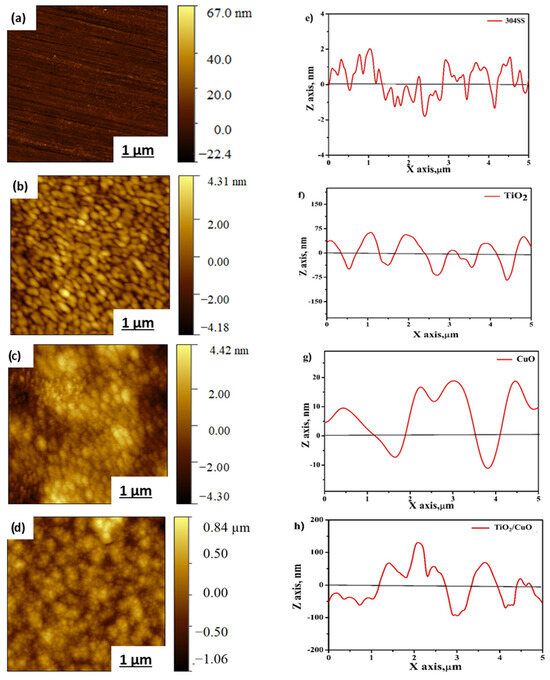
Figure 6.
Atomic force microscopy contact-mode 2D topography images of (a) bare 304SS, (b) TiO2, (c) CuO, and (d) TiO2/CuO (0.005). Line profiles of (e) bare 304SS, (f) TiO2, (g) CuO, and (h) TiO2/CuO (0.005) heterostructures coated on 304 stainless steel (304SS).
The line profile analysis highlights the height and depth profiles of the coated heterostructures. Figure 6e–h displays the line profiles for bare 304SS, TiO2, CuO, and the TiO2/CuO heterostructure, respectively. These profiles reveal sub-micrometer to nanometer-scale pores, with peak-to-peak height variations ranging from 25 nm to 200 nm. The AFM line profile analysis suggests that the activity of the thin film is strongly dependent on particle curvature, with crests indicating the sample’s dimensional features and troughs corresponding to pore locations [63,64]. From Figure 6e, the line profile of bare 304SS shows surface wavy and uneven features with smooth transitions. It reveals a relatively flat surface with minor fluctuations, confirming the low roughness. From Figure 6f, the TiO2 coating shows distinct peaks and valleys in the line profile, indicating a rough and uneven surface. The profile suggests that the TiO2 film has a slightly porous structure, which correlates with the increased roughness observed in the 2D topography. From Figure 6g, the CuO line profile reveals more significant surface features, indicating the presence of larger CuO crystals. The profile shows deep valleys and higher peaks, suggesting the more textured nature of the CuO surface. The analysis of AFM height profile images quantitatively evaluated particle sizes and surface features using Gwyddion 2.63 software. At least five different surface regions per sample were analyzed to ensure statistical reliability, and the average values for roughness and peak-to-peak height were calculated. The AFM line profiles (Figure 6e–h) highlight the topographical variations across samples. These profiles indicate nanometer to sub-micrometer-scale features, with estimated particle sizes ranging from 75 nm to 200 nm and peak-to-peak height differences from 25 to 200 nm, as shown in Figure 6h, which may enhance electrolyte interaction, supporting improved photocathodic and corrosion-resistant performance on 304SS [61,63,64]. Although increased surface roughness enhances electrolyte contact, it does not reduce corrosion resistance if the surface architecture is well controlled. In this study, the TiO2/CuO coatings exhibit nanoscale roughness and optimized porosity, which improve light absorption and facilitate efficient charge transfer under illumination. At the same time, the uniform and compact surface structure acts as a barrier, preventing electrolyte penetration and localized corrosion. Thus, the tailored morphology supports enhanced photocathodic performance and corrosion protection of 304SS.
3.6. Open Circuit Potential
The open-circuit potential (OCP) was monitored over time to examine the corrosion resistance and passivation behavior of TiO2/CuO heterostructure coatings on 304 stainless steel (304SS) in a 3.5% NaCl solution under dark and illuminated conditions, each for 30 min [38]. Figure 7a represents the OCP values as a function of immersion time for the uncoated 304SS, CuO, TiO2, and TiO2/CuO heterostructures with varying CuO concentrations (TiO2/CuO (0.001), TiO2/CuO (0.005), TiO2/CuO (0.01), and TiO2/CuO (0.05)) coated on 304SS under dark and light conditions. The presented values correspond to the final stabilized OCP values obtained after 30 min of continuous exposure. Under dark conditions, the pristine 304SS exhibited an OCP value of –243 mV (vs SCE), indicating the formation of a protective passivation layer. Pure CuO showed a slightly positive shift, with OCP values of −241 mV (vs. SCE), while TiO2 exhibited a more positive change from −236 mV (vs. SCE). In comparison, the TiO2/CuO heterostructures showed varying results: the TiO2/CuO (0.001) and TiO2/CuO (0.005) coatings displayed positive shifts to approximately −234 and −231 mV (vs. SCE), suggesting adequate corrosion protection, while the TiO2/CuO (0.01) and TiO2/CuO (0.05) coatings exhibited negative potential shifts to approximately −237 and −242 mV (vs. SCE), likely due to defects or increased porosity in the coatings. Among the heterostructures, TiO2/CuO (0.005) provided the most stable and positive OCP, indicating superior corrosion resistance in dark conditions. Under light conditions, the OCP of pristine 304SS remained almost unchanged at −243 mV, as it lacks a photocathodic effect and is not inherently photoactive. Pure CuO showed a significant negative shift to −245 mV, while TiO2 shifted more negatively to −248 mV, indicating a moderate photocathodic effect. TiO2/CuO (0.001) and TiO2/CuO (0.005) exhibited the most significant negative shifts, reaching −250 mV and −253 mV, respectively, thereby enhancing photocathodic protection. TiO2/CuO (0.01) and TiO2/CuO (0.05) showed smaller shifts to −249 mV and −247 mV, likely due to defects in the coatings and excessive CuO content, which introduces recombination centers for electrons and holes, which hinder charge transfer from the TiO2/CuO composite to the 304SS substrate. TiO2/CuO (0.005) provided optimal photocathodic protection under light [38,65,66,67].
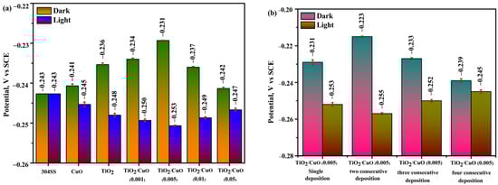
Figure 7.
Bar diagrams of open-circuit potential (OCP): (a) OCP of 304SS coated with TiO2/CuO heterostructures at different CuO concentrations, and (b) OCP of the optimized TiO2/CuO heterostructure with varying deposition thicknesses.
Figure 7b shows the OCP values for the TiO2/CuO (0.005) coating with varying consecutive depositions under dark and light conditions. For a single deposition, the OCP value was −231 mV (vs SCE), while two consecutive depositions gave an OCP value of −223 mV (vs SCE). Three consecutive depositions resulted in an OCP value of −233 mV (vs SCE), and four consecutive depositions gave an OCP value of −239 mV (vs SCE) under dark conditions. Under light, the single deposition showed a value of −253 mV (vs SCE), two consecutive depositions had an OCP value of −255 mV (vs SCE), three consecutive depositions showed an OCP value of −252 mV (vs SCE), and four consecutive depositions gave an OCP value of −245 mV (vs SCE). The TiO2/CuO (0.005) coating with two consecutive depositions exhibited the most positive corrosion potential under dark conditions, indicating enhanced corrosion protection. In contrast, the two consecutive depositions provided the most negative OCP value under light, suggesting optimal photocathodic protection. Based on these results, the TiO2/CuO (0.005) coating with two consecutive depositions was identified as the optimal configuration for corrosion protection and was further investigated for photocathodic corrosion protection under light illumination [68,69].
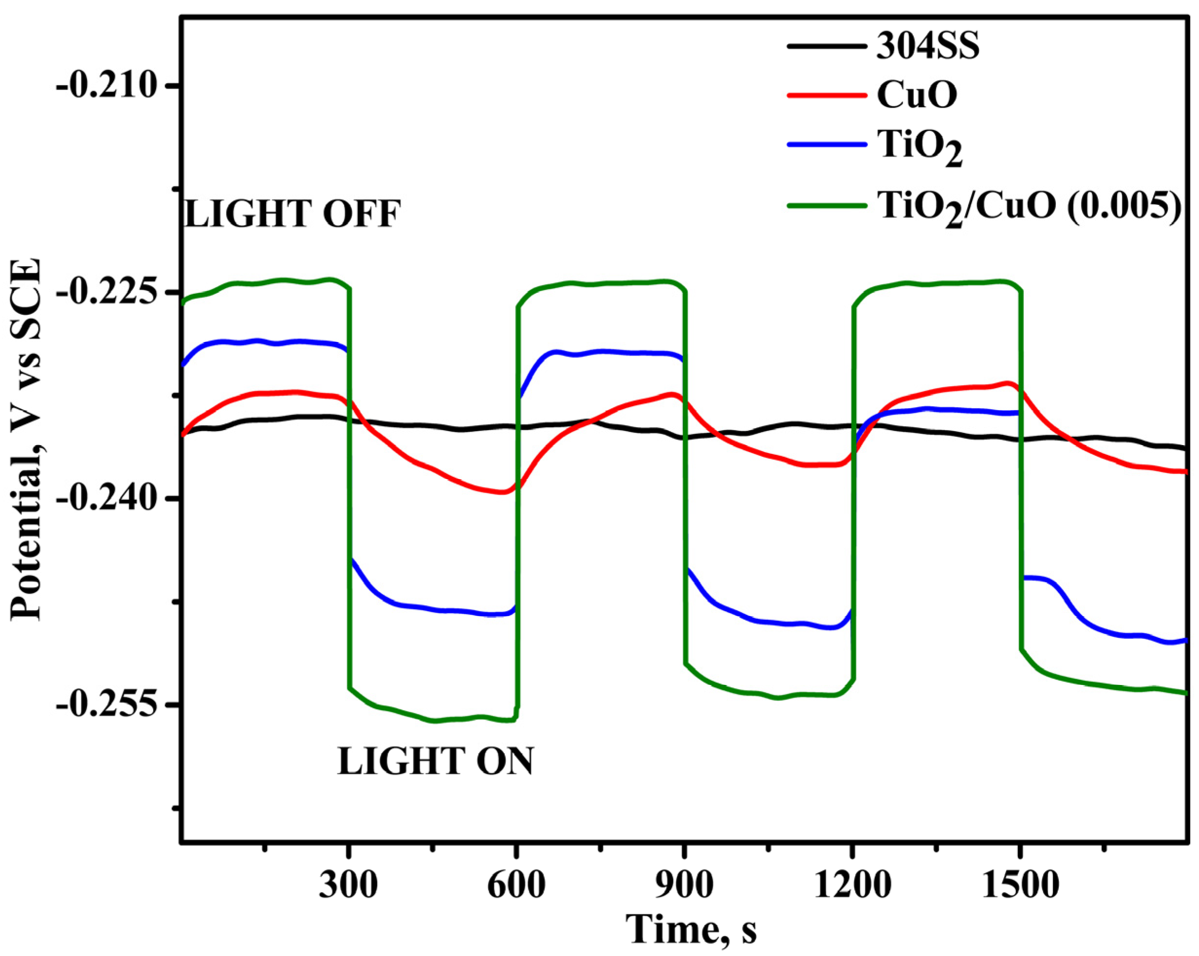
As shown in Figure 8, under light irradiation, the OCP values of the TiO2/CuO-coated 304SS shifted toward more negative potentials, suggesting the generation of photocurrent as a result of photoexcited electrons transitioning from the valence band to the conduction band [70,71]. For instance, the corrosion potential of TiO2/CuO (0.005) changed from −0.234 V (vs. SCE) to −0.255 V (vs. SCE) under light illumination, highlighting the improved photocathodic corrosion protection provided by the TiO2/CuO (0.005) coating. The significant variations in the corrosion potential with light ON/OFF conditions observed for the TiO2/CuO (0.005) coating further indicate its effectiveness in providing photocathodic corrosion protection for 304SS. These results demonstrate the potential of TiO2/CuO heterostructures in improving corrosion resistance in environments exposed to light irradiation.

Figure 8.
Open circuit potential (OCP) diagram for pristine 304SS, CuO, TiO2, and TiO2/CuO coatings under solar stimulation lamp 150 W ON/OFF conditions in a 3.5% NaCl solution.
3.7. Chronoamperometry
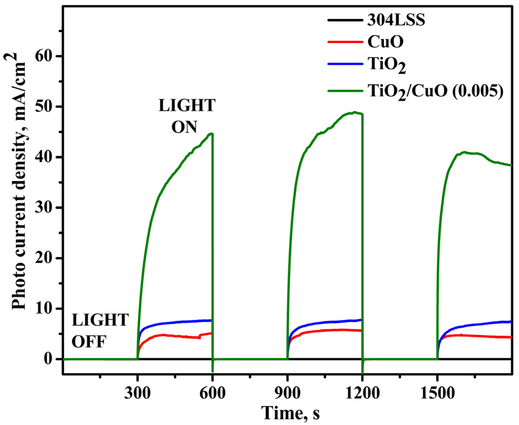
Figure 9 presents the transient photocurrent responses of uncoated 304SS, CuO, TiO2, and TiO2/CuO-coated 304SS under visible light illumination. In the absence of light, all samples exhibited a negligible photocurrent density (~0 mA/cm2). A sharp rise in photocurrent density was observed upon lighting, indicating efficient photoresponse and successful migration of photo-generated electrons to the 304SS substrate. The pure CuO electrode generated a photocurrent density of approximately 4.2 mA/cm2, whereas pure TiO2 exhibited a higher value of around 7.6 mA/cm2 despite its limited absorption in the visible spectrum [72].
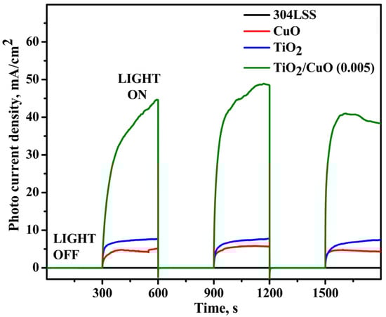
Figure 9.
Chronoamperometry for pristine 304SS, CuO, TiO2, and TiO2/CuO (0.005) coatings under solar stimulation lamp 150 W ON/OFF conditions in a 3.5% NaCl solution.
However, after sensitization with CuO nanoparticles, the transient photocurrent densities of TiO2/CuO coated samples increase significantly, indicating that the TiO2/CuO nanocomposite can efficiently utilize visible light. The heterostructure formation promotes efficient separation of photo-generated electron-hole pairs, enhancing the photocurrent response. Among the various TiO2/CuO configurations, the TiO2/CuO (0.05) photoelectrode exhibits the highest transient photocurrent density, indicating superior charge carrier separation efficiency. Upon visible light irradiation, the photocurrent rises sharply, with the positive current signifying electron transfer from the photoanode to the 304SS substrate. This electron flow drives a Faradaic reaction at the electrode surface, reducing reactive oxygen species in the electrolyte. Consequently, this process mitigates corrosion at the 304SS interface [73,74]. The largest photocurrent of 49 mA/cm2 was observed for the TiO2/CuO (0.005) photoelectrode, indicating its superior photocathodic protection performance and being approximately 5-fold higher than bare 304SS.
Upon illumination, all photoelectrodes showed a notable photocurrent. When the light source was turned off, the photocurrent density returned to its initial value, confirming that light exposure facilitates the separation of valence band electrons and holes in the semiconductor, leading to photocurrent generation. In the dark, the recombination of these charge carriers occurs, preventing the formation of a photocurrent.
3.8. Potentiodynamic Polarization
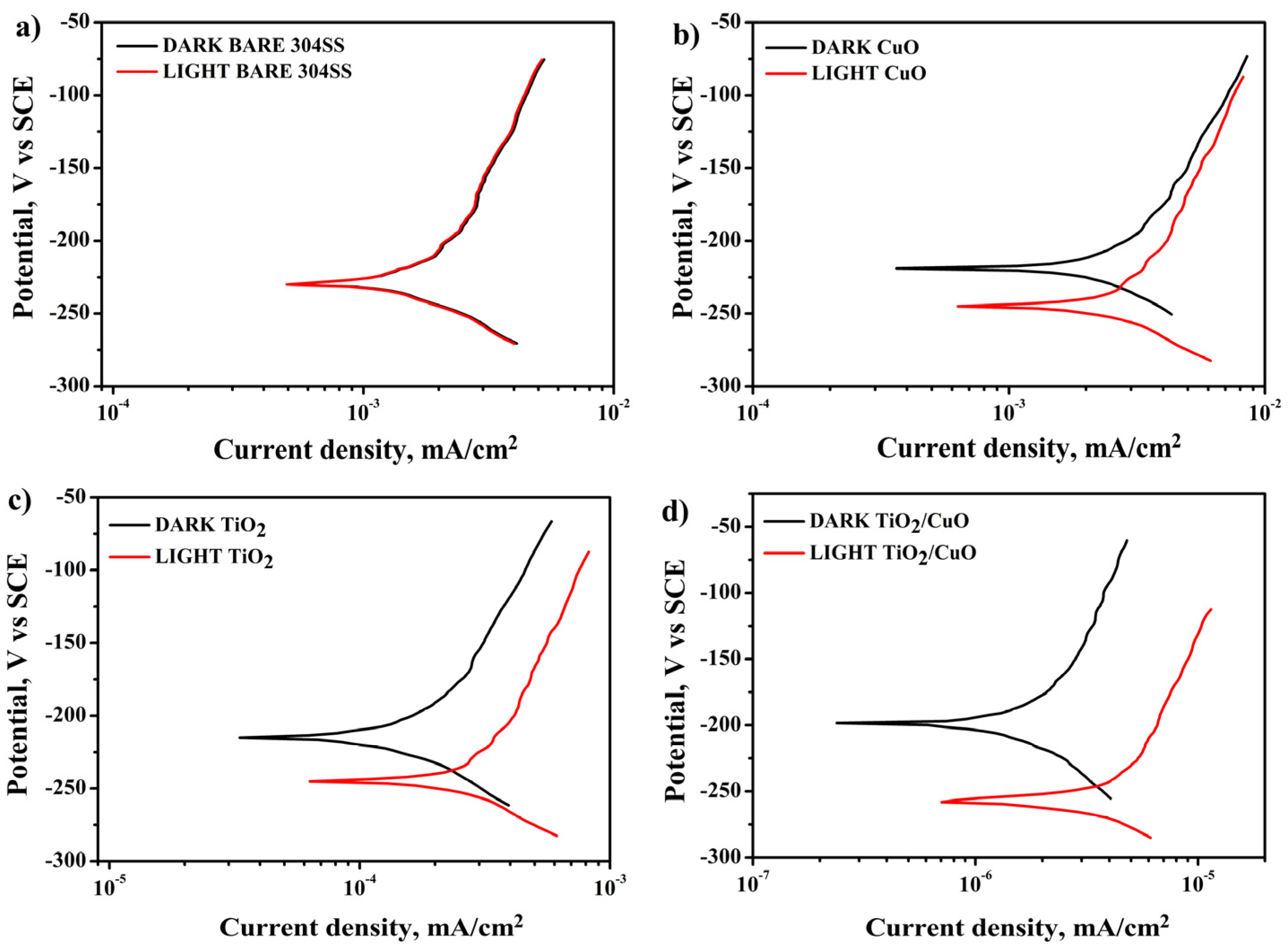
Figure 10a shows that the polarization curve of uncoated 304SS exhibits no significant shift in corrosion potential (Ecorr) or corrosion current density (Icorr) under light ON/OFF conditions. In contrast, Figure 10b–d demonstrates that the CuO, TiO2, and TiO2/CuO coated electrodes exhibit more positive corrosion potentials (Ecorr) of −232, −228, and −223 mV (vs. SCE), respectively, compared to the 304SS corrosion potential (Ecorr) of −234 mV (vs. SCE) under dark conditions. This indicates that the TiO2/CuO heterostructure coating is an effective barrier layer, protecting the 304SS substrate from corrosion without light [75]. Under light irradiation, as seen in Figure 10b–d, a negative shift in Ecorr (−239, −249, and −255 mV vs. SCE) is observed for the CuO, TiO2, and TiO2/CuO coated samples. This shift occurs because photoelectrons from the TiO2/CuO heterostructure are injected into the 304SS substrate, resulting in a significant drop in polarization potential. The corresponding increase in corrosion current density reflects the enhanced photocathodic corrosion protection effect for 304SS. Among the tested samples, the TiO2/CuO (0.005) coating exhibited the most effective photocathodic corrosion protection under illumination. This improvement is ascribed to the polarization of photo-generated electrons, which enhances electrochemical reactions at the interface. The superior performance of TiO2/CuO coatings stems from their heterojunction structure, which improves charge separation and inhibits electron-hole recombination [76]. Thus, the TiO2/CuO-coated 304SS is a corrosion barrier and a photocathodic protection layer.
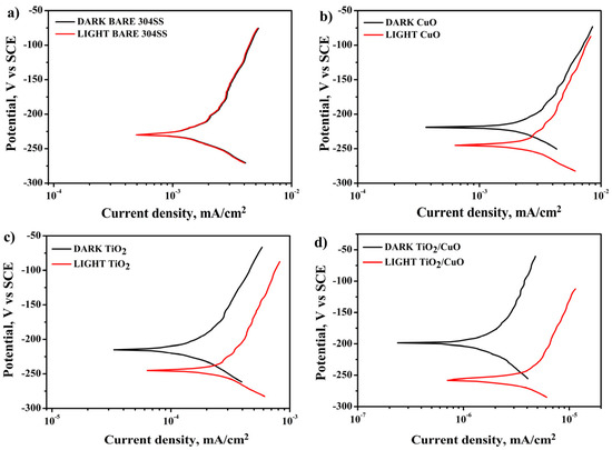
Figure 10.
Potentiodynamic polarization diagram for (a) 304SS in dark and light, (b) CuO in dark and light, (c) TiO2 in dark and light, and (d) TiO2/CuO in dark and light conditions in 3.5% NaCl.
The corrosion potential and current density for bare 304SS were evaluated as −234 mV (vs. SCE) and 8 × 10⁻² mA/cm2, respectively. The TiO2/CuO (0.005) composite coating demonstrated significantly improved corrosion resistance, with a more positive corrosion potential of −255 mV (vs. SCE) and a drastically reduced corrosion current density of 0.46 × 10⁻⁶ mA/cm2. The negative shift in Ecorr indicates effective cathodic polarization of the substrate under illumination caused by the injection of photo-generated electrons from the composite layer to the metal surface. Meanwhile, the significant decrease in Icorr is due to the suppression of anodic dissolution, as the continuous supply of electrons from the photoactive coating reduces the driving force for metal corrosion. These results highlight the superior protective properties of the TiO2/CuO composite layer over uncoated 304SS and substrates coated with CuO or TiO2 individually.
Additionally, the results from Figure 10b–d show an appreciable negative shift in Ecorr and Icorr values under light ON conditions. This shift indicates that the TiO2/CuO coating prevents the release of metal ions and efficiently transfers photoexcited electrons to the 304SS surface. These results match the previous open circuit potential and chronoamperometry data, and the polarization technique confirms that the TiO2/CuO (0.005) coating provides superior photocathodic corrosion protection, making it the optimal coating for enhancing the durability of 304SS in a 3.5% NaCl solution [77,78]. The TiO2/CuO (0.005) heterostructure coating demonstrated a significant reduction in corrosion rate, decreasing from 169 mm/year (for bare 304SS under illumination) to just 21.6 mm/year. This corresponds to a corrosion protection efficiency of approximately 80%.
3.9. Electrochemical Impedance Spectroscopy
Electrochemical Impedance Spectroscopy (EIS) was used to study the interfacial properties of TiO2/CuO coatings on 304 stainless steel (304SS). The impedance data were fitted with equivalent circuit models shown in Figure 11, RS(Q1R1) for uncoated 304SS and Rs(Q1R1)(Q2R2) for coated 304SS. In these circuits, the charge transfer resistance (R1) and double-layer capacitance (Q1) at the electrolyte/film interface are connected in parallel and in series with the solution resistance (RS). For the coated substrate, the Randles circuit was extended with a second parallel branch (R2Q2), representing the charge transfer resistance and double-layer capacitance at the film–metal interface due to the heterostructure coating. This arrangement is particularly suitable for systems where charge transfer processes and double-layer capacitance play significant roles. To assess the quality of the fit, the chi-square (χ2) values were calculated for all fittings and found to be below 10−3, indicating an excellent fit. The fitted parameters were tabulated in Table 2.

Figure 11.
Impedance schematic circuit diagram for pristine 304SS and coated 304SS.
Table 2.
Fitted electrochemical impedance spectroscopy (EIS) parameters for uncoated and coated 304SS under dark and light conditions based on equivalent circuit modeling.
As shown in the Nyquist plots (Figure 12), RS represents the electrolyte resistance, which remains stable under dark and light conditions. Q1 and Q2 reflect surface roughness, charge effects, coating quality, and light-induced charges at the electrolyte/coating and coating/metal interfaces, respectively. Under illumination, both Q1 and Q2 slightly increased due to photo-induced surface charges. At the same time, the n values remained close to unity, indicating relatively uniform surfaces with moderate deviation from ideal capacitive behavior. R1 and R2 correspond to the charge transfer resistance at the electrolyte/coating and coating/metal interfaces; both are higher in the dark, indicating better corrosion resistance, and decrease under light due to photo-generated electrons enhancing charge transfer. The semicircle in the Nyquist plot corresponds to the charge transfer resistance (R1) at the interface between the electrode and the electrolyte. The formation of the TiO2/CuO heterojunction and the improvement in crystallinity significantly reduce R1, indicating enhanced charge transfer across the interface.
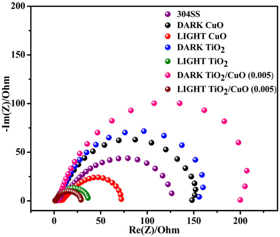
Figure 12.
Impedance spectra for pristine 304SS, CuO, TiO2, and TiO2/CuO coatings under solar stimulation lamp 150 W ON/OFF conditions in a 3.5% NaCl solution.
The R1 values for 304SS, CuO, TiO2, and TiO2/CuO heterostructures under dark conditions were 126, 147, 156, and 201 Ωcm2, respectively. Under light conditions, the R1 values were 126, 71, 35, and 27 Ωcm2. The reduction in R1 values is attributed to the injection of photo-generated electrons from the TiO2/CuO composite into the 304SS electrode, accelerating the electrochemical reaction at the metal–film interface [79]. The second semicircle in the Nyquist plot corresponds to the charge transfer resistance (R2) at the interface between the coating and the metal substrate. The TiO2/CuO heterojunction enhances the coating’s barrier properties, resulting in higher R2 values under dark conditions, indicating improved corrosion resistance. The R2 values for coated 304SS under dark conditions were 28, 43, 63, and 91 Ωcm2 for CuO, TiO2, and TiO2/CuO heterostructures, respectively. Under light conditions, these values decreased to 28, 36, 54, and 27 Ωcm2, respectively. The decrease in R2 under illumination is due to photo-generated electrons facilitating charge transfer at the coating/metal interface, accelerating the electrochemical processes at this boundary [80]. Interestingly, the semicircle radius of the TiO2/CuO heterostructure is much smaller than that of CuO and TiO2 films, indicating enhanced electron transport efficiency between the film and the metal substrate. These findings confirm that the TiO2/CuO heterostructure film significantly improves the separation and transfer of photo-generated electron-hole pairs. Consequently, injecting more electrons into the 304SS substrate improves photocathodic corrosion protection under light illumination. Under illumination, the TiO2/CuO heterostructure injects photo-generated electrons into the 304SS substrate, shifting its corrosion potential cathodically and suppressing anodic dissolution. This is reflected in the decreased R1 values from EIS and the lower corrosion currents from polarization tests. Together, these results confirm that TiO2/CuO is an effective barrier and an active promoter of interfacial charge transfer, significantly enhancing photocathodic protection under light [81,82,83,84].
3.10. Mott–Schottky Analysis
Mott–Schottky (MS) analysis was conducted to investigate the flat-band potentials and semiconductor behavior of the pristine and heterostructured samples, as illustrated in Figure 13. The flat-band potentials (Vfb) were extracted from the linear regions of the 1/C2 versus potential plots. For pristine TiO2 (Figure 13a), the Vfb was determined to be approximately –0.39 V (vs. SCE), confirming its n-type semiconductor nature. In contrast, CuO (Figure 13b) exhibited a positive Vfb of +0.52 V (vs. SCE), characteristic of a p-type semiconductor. The TiO2/CuO (0.005) heterostructure (Figure 13c) displayed dual linear regions, indicating the presence of both n-type and p-type domains, with corresponding flat-band potentials at –0.21 V and +0.89 V (vs. SCE). This dual behavior signifies the formation of a p–n heterojunction, where intimate contact between n-type TiO2 and p-type CuO facilitates the creation of a built-in electric field that promotes charge carrier separation. The observed shift in the flat-band potentials of the heterostructure indicates enhanced charge separation and improved photoelectrochemical properties due to the formation of a favorable type II heterojunction. This interfacial electronic coupling suppresses recombination and enhances photo-induced electron transfer toward the metal substrate. Therefore, the TiO2/CuO (0.005) heterostructure is a promising candidate for enhanced photocathodic protection due to its synergistic electronic properties and efficient charge separation mechanism.
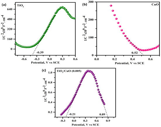
Figure 13.
Mott–Schottky plots (1/C2 vs. potential) measured at 1 kHz for (a) TiO2, (b) CuO, and (c) TiO2/CuO (0.005) heterostructure electrodes in 3.5% NaCl electrolyte.
3.11. Proposed Photocathodic Protection Mechanism of TiO2/CuO Heterostructure
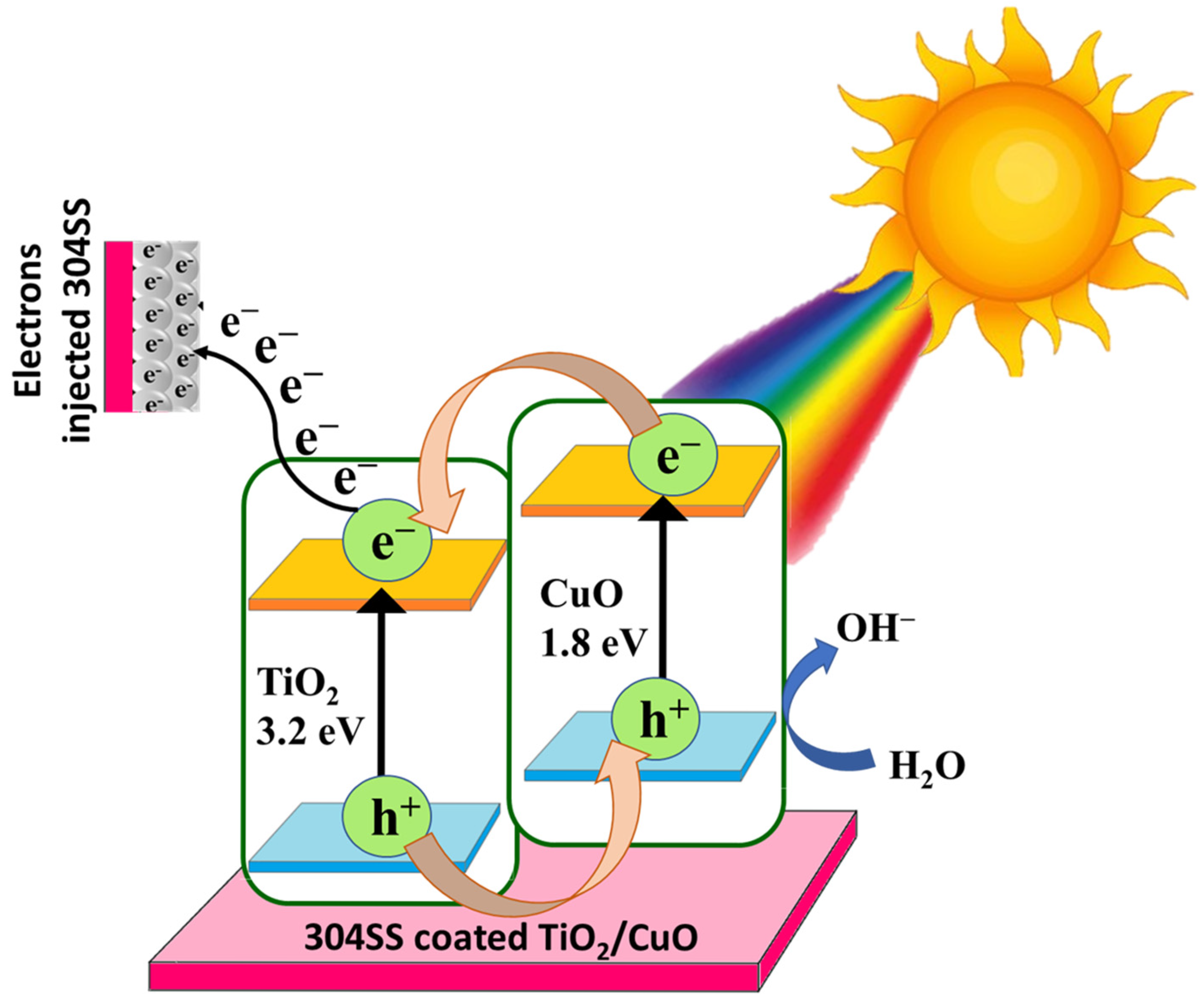
The photocathodic protection mechanism of the TiO2/CuO heterostructure coated on 304 stainless steel is primarily attributed to the formation of a type-II heterojunction, which has been substantiated through a combination of UV–Vis diffuse reflectance spectroscopy (DRS), Tauc plot bandgap estimations, and Mott–Schottky (MS) analysis. Mott–Schottky analysis confirms the formation of a Type-II heterojunction between n-type TiO2 (flat band ~−0.39 V) and p-type CuO (flat band ~+0.52 V), with shifted potentials in the composite (−0.21 V and +0.89 V). This heterojunction promotes an internal electric field that drives efficient charge separation under visible light.
UV confirms that the pure TiO2 displayed a wide bandgap of 3.20 eV, limiting its activity to the UV region. CuO, with a narrow bandgap of 1.80 eV, exhibited strong absorption in the visible region. Interestingly, the TiO2/CuO (0.005) heterostructure showed a reduced bandgap of 2.17 eV, indicating enhanced visible-light absorption due to interfacial interaction and successful hybridization between the two semiconductors. Under visible-light irradiation, electrons in CuO are excited from its valence band (VB) to the conduction band (CB). Due to the Type-II band alignment, these electrons preferentially transfer to the more negative CB of TiO2. Simultaneously, photo-generated holes in TiO2’s VB migrate to CuO’s VB. This directional migration of charge carriers across the heterojunction spatially separates electrons and holes, effectively reducing their recombination rate and prolonging their lifetime. The electrons accumulated on TiO2’s conduction band can then flow to the 304SS substrate, increasing the cathodic current and suppressing the anodic dissolution of the stainless steel [59]. Such a charge transfer pathway is particularly favorable for photocathodic protection applications. The accumulation of electrons on TiO2 enhances the cathodic current on the 304SS substrate, suppressing its anodic dissolution and improving corrosion resistance under illumination.
In conclusion, the synergistic integration of TiO2 and CuO in the 0.005 composition leads to a well-aligned Type-II heterojunction [85,86]. The observed shifts in flat band potentials and the narrowed bandgap support this mechanism, establishing the TiO2/CuO (0.005) system as a promising candidate for visible-light-driven corrosion protection of 304 stainless steel. The schematic representation of the proposed photocathodic corrosion protection mechanism based on the Type-II heterojunction formed between TiO2 and CuO coated on 304 stainless steel is shown in Figure 14.

Figure 14.
Schematic representation of the proposed photocathodic corrosion protection mechanism based on the Type-II heterojunction formed between TiO2 and CuO coated on 304 stainless steel.
4. Conclusions
The TiO2/CuO heterostructure was synthesized by the sol–gel method and coated onto 304SS to enhance the longevity of seashore appliances. This study successfully demonstrates the photocathodic corrosion protection abilities of the TiO2/CuO heterostructure under light illumination. UV–visible diffuse reflectance spectroscopy (UV-DRS) confirmed the improved visible light absorption of the TiO2/CuO heterostructure, enabling efficient utilization of solar irradiation. Mott–Schottky analysis revealed increased charge carrier density and favorable band alignment, facilitating effective separation of photo-generated electron-hole pairs and promoting electron transfer to the 304SS substrate. The Raman spectra of TiO2/CuO heterostructures on 304SS confirm the formation of TiO2 and CuO phases, with shifts in the TiO2 Eg mode indicating strong interaction between the components. FTIR spectra show O-H stretching and metal–oxygen bonds, supporting the heterostructure formation. AFM and SEM images reveal increased surface roughness and uniform morphology, enhancing stability. OCP measurements indicate improved corrosion resistance, with the TiO2/CuO (0.005) coating showing OCP values of −223 mV in the dark and −255 mV under light. Photocurrent density measurements under visible light reveal that the TiO2/CuO (0.005) coating exhibits the highest photocurrent (49 mA/cm2), which is 5-fold higher than bare 304SS. These results demonstrate that TiO2/CuO coatings significantly improve corrosion protection and photocathodic performance, particularly for stainless steel in light-exposed environments.
5. Future Perspective
Integration into offshore appliances: Since 304SS is extensively used in offshore appliances, future research can explore the integration of the TiO2/CuO heterostructure coating into oil field pipelines and offshore applications. This includes studying the interaction between the coating and evaluating its impact on the overall performance and durability of oil field pipelines and offshore appliances.
Author Contributions
A.R. (Abinaya Radhakrishnan): writing—original draft, methodology, investigation, formal analysis. M.T.: methodology, formal analysis. N.S.: supervision, methodology, funding acquisition, data curation, conceptualization, writing—review and editing, validation. A.R. (Anuradha Ramani).: data curation and conceptualization. All authors have read and agreed to the published version of the manuscript.
Funding
This research received no external funding.
Institutional Review Board Statement
Not applicable.
Informed Consent Statement
Not applicable.
Data Availability Statement
Data will be made available upon request.
Acknowledgments
The author, Nagarajan Srinivasan, gratefully acknowledges the Tamil Nadu State Government Higher Education (H2) Department for establishing the Sir C V Raman Centre for Instrument Facility (GO (Ms) No. I59) and the DST-FIST Project (SR/FST/CSI—247/2012) and for their infrastructure support.
Conflicts of Interest
The authors declare no conflict of interest.
References
- Li, H.; Wang, X.; Wei, Q.; Hou, B. Photocathodic Protection of 304 Stainless Steel by Bi2S3/TiO2 Nanotube Films under Visible Light. Nanoscale Res. Lett. 2017, 12, 80. [Google Scholar] [CrossRef] [PubMed]
- Zhang, Y.; Yin, X.Y.; Yan, F.Y. Effect of Halide Concentration on Tribocorrosion Behaviour of 304SS in Artificial Seawater. Corros. Sci. 2015, 99, 272–280. [Google Scholar] [CrossRef]
- Zhang, Y.; Yin, X.Y.; Yan, Y.F.; Wang, J.; Yan, F. Tribocorrosion Behaviors of 304SS: Effect of Solution pH. RSC Adv. 2015, 5, 17676–17682. [Google Scholar] [CrossRef]
- Park, J.H.; Park, J.M. Photo-Generated Cathodic Protection Performance of Electrophoretically Co-Deposited Layers of TiO2 Nanoparticles and Graphene Nanoplatelets on Steel Substrate. Surf. Coat. Technol. 2014, 258, 62–71. [Google Scholar] [CrossRef]
- Wang, X.; Xu, H.; Nan, Y.; Sun, X.; Duan, J.; Huang, Y.; Hou, B. Research Progress of TiO2 Photocathodic Protection to Metals in the Marine Environment. J. Oceanol. Limnol. 2020, 38, 1018–1044. [Google Scholar] [CrossRef]
- Yuan, J.; Tsujikawa, S. Characterization of Sol-Gel-Derived TiO2 Coating on Carbon Steel in Alkaline Solution. Zairyo-to-Kankyo 1995, 44, 534–542. [Google Scholar] [CrossRef]
- Qiu, X.; Gou, G.; Zhang, K.; Zhang, X.; Sun, W.; Qin, S.; Luo, X.; Feng, P.; Pan, J.; Gao, W. Investigation on TiO2 Photocathodic Protection Based on Lattice Distortion and Stress Engineering. Mater. Today Commun. 2023, 35, 105782. [Google Scholar] [CrossRef]
- Yuan, J.; Tsujikawa, S. Characterization of Sol-Gel-Derived TiO2 Coatings and Their Photoeffects on Copper Substrates. J. Electrochem. Soc. 1995, 142, 3444–3450. [Google Scholar] [CrossRef]
- Dubey, R.S.; Krishnamurthy, K.V.; Singh, S. Experimental Studies of TiO₂ Nanoparticles Synthesized by Sol-Gel and Solvothermal Routes for DSSCs Application. Results Phys. 2019, 14, 102390. [Google Scholar] [CrossRef]
- Li, M.; Luo, S.; Wu, P.; Shen, J. Photocathodic Protection Effect of TiO2 Films for Carbon Steel in 3% NaCl Solutions. Electrochim. Acta 2005, 50, 3401–3406. [Google Scholar] [CrossRef]
- Zhang, Y.; Bu, Y.Y.; Yu, J.Q.; Li, P. Highly Efficient Photoelectrochemical Performance of SrTiO3/TiO2 Heterojunction Nanotube Array Thin Film. J. Nanoparticle Res. 2013, 15, 1717. [Google Scholar] [CrossRef]
- Liu, L.; Hu, J.M.; Leng, W.H.; Zhang, J.Q.; Cao, C.N. Novel Bis-Silane/TiO2 Bifunctional Hybrid Films for Metal Corrosion Protection Both under Ultraviolet Irradiation and in the Dark. Scr. Mater. 2007, 57, 549–552. [Google Scholar] [CrossRef]
- Zhang, Y.; Yu, J.; Sun, K.; Zhu, Y.; Bu, Y.; Chen, Z. Indium Oxide Thin Film as Potential Photoanodes for Corrosion Protection of Stainless Steel under Visible Light. Mater. Res. Bull. 2014, 53, 251–256. [Google Scholar] [CrossRef]
- Wipataphan, P.; Laohawattanajinda, J.; Na Wichean, T.; Sripianem, W.; Techapiesancharoenkij, R. Photocathodic Protection of Amorphous and Nanorod Zinc Oxide Thin-Film Coatings on Stainless Steel AISI 304 Fabricated by Spray Pyrolysis and Hydrothermal Technique. Mater. Chem. Phys. 2022, 291, 126714. [Google Scholar] [CrossRef]
- Zhang, X.; Chen, G.; Li, W.; Wu, D. Photocathodic Protection of Cobalt-Doped ZnO Nanorod Arrays for 316 Stainless Steel and Q235 Carbon Steel in 3.5 wt.% NaCl Solution. Coatings 2019, 9, 803. [Google Scholar] [CrossRef]
- Wang, X.; Guan, Z.C.; Jin, P.; Tang, Y.Y.; Song, G.L.; Liu, G.K.; Du, R.G. Facile Fabrication of BiVO4-Modified TiO2 Nanotube Film Photoanode and Its Photocathodic Protection Effect on Stainless Steel. Corros. Sci. 2019, 157, 247–255. [Google Scholar] [CrossRef]
- Guan, Z.C.; Wang, H.P.; Wang, X.; Hu, J.; Du, R.G. Fabrication of Heterostructured β-Bi2O3-TiO2 Nanotube Array Composite Film for Photoelectrochemical Cathodic Protection Applications. Corros. Sci. 2018, 136, 60–69. [Google Scholar] [CrossRef]
- Dohcevic-Mitrovic, Z.; Stojadinovic, S.; Lozzi, L.; Askrabic, S.; Rosic, M.; Tomic, N.; Paunovic, N.; Lazovic, S.; Nikolic, M.G.; Santucci, S. WO₃/TiO₂ Composite Coatings: Structural, Optical and Photocatalytic Properties. Mater. Res. Bull. 2016, 83, 217–224. [Google Scholar]
- Li, S.; Fu, J. Improvement in Corrosion Protection Properties of TiO2 Coatings by Chromium Doping. Corros. Sci. 2013, 68, 101–110. [Google Scholar] [CrossRef]
- Zhang, J.; Du, R.G.; Lin, Z.Q.; Zhu, Y.F.; Guo, Y.; Qi, H.Q.; Xu, L.; Lin, C.J. Highly Efficient CdSe/CdS Co-Sensitized TiO2 Nanotube Films for Photocathodic Protection of Stainless Steel. Electrochim. Acta 2012, 83, 59–64. [Google Scholar] [CrossRef]
- Lei, C.X.; Zhou, H.; Wang, C.; Feng, Z.D. Self-Assembly of Ordered Mesoporous TiO2 Thin Films as Photoanodes for Cathodic Protection of Stainless Steel. Electrochim. Acta 2013, 87, 245–249. [Google Scholar] [CrossRef]
- Zhu, Y.F.; Xu, L.; Hu, J.; Zhang, J.; Du, R.G.; Lin, C.J. Fabrication of Heterostructured SrTiO3/TiO2 Nanotube Array Films and Their Use in Photocathodic Protection of Stainless Steel. Electrochim. Acta 2014, 121, 361–368. [Google Scholar] [CrossRef]
- Leppäniemi, J.; Sippola, P.; Broas, M.; Aromaa, J.; Lipsanen, H.; Koskinen, J. Corrosion Protection of Steel with Multilayer Coatings: Improving the Sealing Properties of Physical Vapor Deposition CrN Coatings with Al2O3/TiO2 Atomic Layer Deposition Nanolaminates. Thin Solid Films 2017, 627, 59–68. [Google Scholar] [CrossRef]
- Guo, H.; Li, L.; Su, C.; Yu, D.; Liu, Z. Effective Photocathodic Protection for 304 Stainless Steel by PbS Quantum Dots Modified TiO2 Nanotubes. Mater. Chem. Phys. 2021, 258, 123914. [Google Scholar] [CrossRef]
- Cai, J.S.; Shen, J.L.; Zhang, X.N.; Ng, Y.H.; Huang, J.H.; Guo, W.X.; Lin, C.J.; Lai, Y.K. Light-Driven Sustainable Hydrogen Production Utilizing TiO2 Nanostructures: A Review. Small Methods 2018, 3, 1800184. [Google Scholar] [CrossRef]
- Yue, L.; Huan, Y.; Liang, W.; Xie, Z.-H.; Zhong, C.-J. Temperature-Controlled and Shape-Dependent ZnO/TiO2 Heterojunction for Photocathodic Protection of Nickel-Coated Magnesium Alloys. Appl. Surf. Sci. 2023, 614, 156109. [Google Scholar]
- Zhang, L.; Wang, X.T.; Liu, F.G. Photo-generated Cathodic Protection of 304SS by ZnSe/TiO2 NTs under Visible Light. Mater. Lett. 2015, 143, 116–119. [Google Scholar] [CrossRef]
- Bjelajac, A.; Petrovic, R.; Socol, G. CdS Quantum Dots Sensitized TiO2 Nanotubes by Matrix Assisted Pulsed Laser Evaporation Method. Ceram. Int. 2016, 42, 9011–9017. [Google Scholar] [CrossRef]
- Tatsuma, T.; Saitoh, S.; Ohko, Y. TiO2-WO3 Photoelectrochemical Anticorrosion System with an Energy Storage Ability. Chem. Mater. 2001, 13, 2838–2842. [Google Scholar] [CrossRef]
- Zhang, D.Y.; Ge, C.W.; Wang, J.Z. Single-Layer Graphene-TiO2 Nanotubes Array Heterojunction for Ultraviolet Photodetector Application. Appl. Surf. Sci. 2016, 387, 1162–1168. [Google Scholar] [CrossRef]
- Motalebian, M.; Momeni, M.M.; Ghayeb, Y.; Atapour, M. Fabrication and Photoelectrochemical Activity of Mn/Cr Co-Doped Titanium Oxide Nanostructures and Their Application in Photocathodic Protection of Stainless Steel. J. Solid State Electrochem. 2023, 27, 357–369. [Google Scholar] [CrossRef]
- Yadav, S.K.; Jeevanandam, P. Synthesis of Ag2S-TiO2 Nanocomposites and Their Catalytic Activity towards Rhodamine B Photodegradation. J. Alloys Compd. 2015, 649, 483–490. [Google Scholar] [CrossRef]
- Xu, S.; Zhang, K.; Du, L.; Gong, D.; Lu, G.; Qiu, P. Zn3In2S6/TiO2 Nanocomposites for Highly Efficient Photocathodic Protection to Carbon Steel. ACS Appl. Nano Mater. 2022, 5, 18297–18306. [Google Scholar] [CrossRef]
- Xue, J.B.; Gao, J.L.; Shen, Q.Q.; Li, Q.; Liu, X.G.; Jia, H.S.; Wu, Y.C. Performance of Photocatalytic Cathodic Protection of 20 Steel by α-Fe2O3/TiO2 System. Surf. Coat. Technol. 2020, 385, 125445. [Google Scholar] [CrossRef]
- Zhou, M.J.; Zhang, N.; Zhang, L.; Yan, J.H. Photocathodic Protection Properties of TiO2-V2O5 Composite Coatings. Mater. Corros. 2012, 64, 996–1000. [Google Scholar] [CrossRef]
- Lu, D.; Zelekew, O.A.; Abay, A.K.; Huang, Q.; Chen, X.; Zheng, Y. Synthesis and Photocatalytic Activities of a TiO2/CuO Composite Catalyst Using Aquatic Plants with Accumulated Copper as a Template. RSC Adv. 2019, 9, 2018–2025. [Google Scholar] [CrossRef]
- Banas-Gac, J.; Radecka, M.; Czapla, A.; Kusior, E.; Zakrzewska, K. Surface and Interface Properties of TiO2/CuOThin Film Bilayers Deposited by RF Reactive Magnetron Sputtering. Appl. Surf. Sci. 2023, 616, 156394. [Google Scholar] [CrossRef]
- Panzeri, G.; Cristina, M.; Jagadeesh, M.S.; Bussetti, G.; Magagnin, L. Modifying Large Area Cu2O/CuO Photocathode with CuS Non-Noble Catalyst for Improved Photocurrent and Stability. Sci. Rep. 2020, 10, 18730. [Google Scholar] [CrossRef]
- Anand, D.; Ravishankar, N.; Sudakar, C. Aluminium-Incorporated p-CuO/n-ZnO Photocathode Coated with Nanocrystal-Engineered TiO2 Protective Layer for Photoelectrochemical Water Splitting and Hydrogen Generation. J. Mater. Chem. A 2018, 6, 11951–11965. [Google Scholar]
- Mehrabi, H.; Eddy, C.G.; Hollis, T.I.; Vance, J.N.; Coridan, R.H. Controlled Exposure of CuO Thin Films through Corrosion-Protecting, ALD-Deposited TiO2 Overlayers. Z. Naturforschung B 2021, 76, 719–726. [Google Scholar] [CrossRef]
- Meng, X.; Zhen, C.; Liu, G.; Cheng, H.M. Stabilizing CuO Photocathode with a Cu3N Protection Shell. Chin. J. Catal. 2022, 43, 755–760. [Google Scholar] [CrossRef]
- Cots, A.; Bonete, P.; Gómez, R. Improving the Stability and Efficiency of CuO Photocathodes for Solar Hydrogen Production through Modification with Iron. ACS Appl. Mater. Interfaces 2018, 10, 26348–26356. [Google Scholar] [CrossRef]
- Patel, M.; Kim, H.S.; Patel, D.B.; Kim, J. CuO Photocathode-Embedded Semitransparent Photoelectrochemical Cell. J. Mater. Res. 2016, 31, 3205–3213. [Google Scholar] [CrossRef]
- SiavashMoakhar, R.; Hosseini-Hosseinabad, S.M.; Masudy-Panah, S.; Seza, A.; Jalali, M.; Fallah-Arani, H.; Dabir, F.; Gholipour, S.; Abdi, Y.; Bagheri-Hariri, M.; et al. Photoelectrochemical Water-Splitting Using CuO-Based Electrodes for Hydrogen Production: A Review. Adv. Mater. 2021, 33, 2007285. [Google Scholar] [CrossRef]
- Toupin, J.; Strubb, H.; Kressman, S.; Artero, V.; Krins, N.; Laberty-Robert, C. CuO Photoelectrodes Synthesised by the Sol-Gel Method for Water Splitting. J. Sol-Gel Sci. Technol. 2019, 89, 255–263. [Google Scholar] [CrossRef]
- Gundogmus, P. Synthesis of g-C3N4/TiO2 Heterojunction Composites with Enhanced Solar Light Photocatalytic Activity. Master’s Thesis, Graduate School of Natural and Applied Sciences, Metallurgical and Materials Engineering, Middle East Technical University, Ankara, Türkiye, 2020. [Google Scholar]
- Chawla, M.K. A Step-by-Step Guide to Selecting the “Right” Solar Simulator for Your Solar Cell Testing Application. Photo Emission Tech.: Moorpark, CA, USA.
- Shi, Q.; Ping, G.; Wang, X.; Xu, H.; Li, J.; Cui, J.; Abroshan, H.; Ding, H.; Li, G. TiO2/CuO Heterojunction Composites: An Efficient Photocatalyst for Selective Oxidation of Methanol to Methyl Formate. J. Mater. Chem. A 2019, 7, 2253–2260. [Google Scholar] [CrossRef]
- Nekooie, R.; Shamspur, T.; Mostafavi, A. Novel TiO2/CuO/PANI Nanocomposite: Preparation and Photocatalytic Investigation for Chlorpyrifos Degradation in Water under Visible Light Irradiation. J. Photochem. Photobiol. A Chem. 2021, 407, 113038. [Google Scholar] [CrossRef]
- Zedan, A.F.; Allam, N.K.; AlQaradawi, S.Y. A Study of Low-Temperature CO Oxidation over Mesoporous CuO–TiO2 Nanotube Catalysts. Catalysts 2017, 7, 129. [Google Scholar] [CrossRef]
- Munawar, K.; Mansoor, M.A.; Basirun, W.J.; Misran, M.; Huang, N.M.; Mazhar, M. Single Step Fabrication of CuO–MnO–2TiO2 Composite Thin Films with Improved Photoelectrochemical Response. RSC Adv. 2017, 7, 15885–15893. [Google Scholar] [CrossRef]
- Deng, C.; Li, B.; Dong, L.; Zhang, F.; Fan, M.; Jin, G.; Zhou, X. NO Reduction by CO over CuO Supported on CeO2-Doped TiO2: The Effect of the Amount of a Few CeO2. Phys. Chem. Chem. Phys. 2015, 17, 16092–16109. [Google Scholar] [CrossRef]
- Fang, J.; Xuan, Y. Investigation of Optical Absorption and Photothermal Conversion Characteristics of Binary CuO/ZnO Nanofluids. RSC Adv. 2017, 7, 56023–56033. [Google Scholar] [CrossRef]
- Fagan, R.; McCormack, D.; Hinder, S.; Pillai, S. Photocatalytic Properties of g-C3N4–TiO2 Heterojunctions under UV and Visible Light Conditions. Materials 2016, 9, 286. [Google Scholar] [CrossRef] [PubMed]
- Rajamannan, B.; Mugundan, S.; Viruthagiri, G.; Praveen, P.; Shanmugam, N. Linear and Nonlinear Optical Studies of Bare and Copper Doped TiO2 Nanoparticles via Sol-Gel Technique. Spectrochim. Acta A Mol. Biomol. Spectrosc. 2014, 118, 651–656. [Google Scholar] [CrossRef] [PubMed]
- A’sraia, A.I.M.; Razali, M.H.; Amin, K.A.M.; Osman, U.M. TiO2/CuO Nanocomposite Photocatalyst for Efficient MO Degradation. Dig. J. Nanomater. Biostruct. 2023, 18, 1005–1124. [Google Scholar] [CrossRef]
- Aydın, E.B.; Ateş, S.; Sığırcık, G. CuO–TiO2 Nanostructures Prepared by Chemical and Electrochemical Methods as Photoelectrode for Hydrogen Production. Int. J. Hydrogen Energy 2022, 47, 6519–6534. [Google Scholar] [CrossRef]
- Tang, Y.; Dong, L.; Deng, C.; Huang, M.; Li, B.; Zhang, H. In Situ FT-IR Investigation of CO Oxidation on TiO2/CuO Catalysts. Catal. Commun. 2016, 78, 33–36. [Google Scholar] [CrossRef]
- Radhakrishnan, A.; Tharmaraj, M.; Srinivasan, N. Photocathodic Corrosion Protection Performance of Aluminium Frames in Solar Panels Using TiO2/C3N4 Heterostructure. J. Alloys Compd. 2025, 1028, 180707. [Google Scholar] [CrossRef]
- Zhou, X.; Lu, J.; Jiang, J.; Li, X.; Lu, M.; Yuan, G.; Wang, Z.; Zheng, M.; Seo, H.J. Simple fabrication of N-doped mesoporous TiO2 nanorods with enhanced visible light photocatalytic activity. Nanoscale Res. Lett. 2014, 9, 34. [Google Scholar] [CrossRef]
- ASTM D3359; Standard Test Methods for Measuring Adhesion by Tape Test. ASTM International: West Conshohocken, PA, USA, 2017.
- Nagarajan, S.; Rajendran, N. Surface Characterisation and Electrochemical Behaviour of Porous Titanium Dioxide Coated 316L Stainless Steel for Orthopaedic Applications. Appl. Surf. Sci. 2009, 255, 3927–3932. [Google Scholar] [CrossRef]
- Fazel, Z.; Elmkhah, H.; Fattah-alhosseini, A.; Babaei, K.; Meghdari, M. Comparing Electrochemical Behavior of Applied CrN/TiN Nanoscale Multilayer and TiN Single-Layer Coatings Deposited by CAE-PVD Method. J. Asian Ceram. Soc. 2020, 8, 510–518. [Google Scholar] [CrossRef]
- Croll, S.G. Surface Roughness Profile and Its Effect on Coating Adhesion and Corrosion Protection: A Review. Prog. Org. Coat. 2020, 148, 105847. [Google Scholar] [CrossRef]
- Ahamed, S.T.; Ghosh, A.; Show, B.; Mondal, A. Fabrication of n-TiO2/p-CuO Thin-Film Heterojunction for Efficient Photocatalytic Degradation of Toxic Organic Dyes and Reduction of Metal Ions in Solution. J. Mater. Sci. Mater. Electron. 2020, 31, 16616–16633. [Google Scholar] [CrossRef]
- Karthega, M.; Raman, V.; Rajendran, N. Influence of Potential on the Electrochemical Behaviour of β Titanium Alloys in Hank’s Solution. Acta Biomater. 2007, 3, 1019–1023. [Google Scholar] [CrossRef] [PubMed]
- Motahari, M.; Nourbakhsh, A.; Bakhsheshi-Rad, H.R.; Lotfian, N.; Masoud, M.; Nourbakhsh, A.H.; Dehkordi, R.D.; Mackenzie, K.J.D. Photocathodic Protection of 316L Stainless Steel by Surface Coating of Photocatalytic Mesoporous TiO2-WO3 Nanocomposite. J. Mater. Eng. Perform. 2023, 32, 10614–10625. [Google Scholar] [CrossRef]
- Sun, W.; Wei, N.; Cui, H.; Lin, Y.; Wang, X.; Tian, J.; Wen, J. 3D ZnIn2S4 Nanosheet/TiO2 Nanowire Arrays and Their Efficient Photocathodic Protection for 304 Stainless Steel. Appl. Surf. Sci. 2018, 434, 1030–1039. [Google Scholar] [CrossRef]
- Chen, T.; Li, B.; Zhang, X.; Ke, X.; Xiao, R. Core–Shell Spheroid Structure TiO2/CdS Composites with Enhanced Photocathodic Corrosion Protection Performance. Materials 2023, 16, 3927. [Google Scholar] [CrossRef]
- Jianjun, Z.; Zia Ur, R.; Youbin, Z.; Chun, Z.; Mengkui, T.; Daoai, W. Nanoflower-Like SnO2–TiO2 Nanotubes Composite Photoelectrode for Efficient Photocathodic Protection of 304 Stainless Steel. Appl. Surf. Sci. 2018, 457, 516–521. [Google Scholar]
- Liu, Y.; Zhu, Z.; Cheng, Y. An In-Depth Study of Photocathodic Protection of SS304 Steel by Electrodeposited Layers of ZnO Nanoparticles. Surf. Coat. Technol. 2020, 399, 126158. [Google Scholar] [CrossRef]
- Lin, Z.Q.; Lai, Y.K.; Hu, R.G. A Highly Efficient ZnS/CdS@TiO2 Photoelectrode for Photo-generated Cathodic Protection of Metals. Electrochim. Acta 2010, 55, 8717–8723. [Google Scholar] [CrossRef]
- Lei, C.X.; Liu, Y.; Zhou, H.; Feng, Z.; Du, R. Photo-generated Cathodic Protection of Stainless Steel by Liquid-Phase-Deposited Sodium Polyacrylate/TiO2 Hybrid Films. Corros. Sci. 2013, 68, 214–222. [Google Scholar] [CrossRef]
- Ge, S.S.; Zhang, Q.X.; Wang, X.T.; Li, H.; Zhang, L.; Wei, Q.Y. Photocathodic Protection of 304 Stainless Steel by MnS/TiO2 Nanotube Films under Simulated Solar Light. Surf. Coat. Technol. 2015, 283, 172–176. [Google Scholar] [CrossRef]
- Tang, H.; Song, Z.; Wang, J.; Qian, B. Photocathodic Protection Performance of a Nonmetal Ternary Heterojunction for 304 Stainless Steel. Inorg. Chem. Commun. 2023, 157, 111426. [Google Scholar] [CrossRef]
- Nan, Y.; Wang, X.; Ning, X.; Lei, J.; Guo, S.; Huang, Y.; Duan, J. Fabrication of Ni3S2/TiO2 Photoanode Material for 304 Stainless Steel Photocathodic Protection under Visible Light. Surf. Coat. Technol. 2019, 377, 124935. [Google Scholar] [CrossRef]
- Jinghai, L.; Tiekai, Z.; Zhichao, W.; Graham, D.; Wei, C. Simple Pyrolysis of Urea into Graphitic Carbon Nitride with Recyclable Adsorption and Photocatalytic Activity. J. Mater. Chem. A 2011, 21, 14398. [Google Scholar]
- Momeni, M.; Motalebian, M. Chromium-Doped Titanium Oxide Nanotubes Grown via One-Step Anodization for Efficient Photocathodic Protection of Stainless Steel. Surf. Coat. Technol. 2021, 420, 127304. [Google Scholar] [CrossRef]
- Techapiesancharoenkij, R.; Sripianem, W.; Tongpul, K.; Peamjharean, C.; Wichean, T.N.; Meesak, T.; Eiamchai, P. Investigation of the Photocathodic Protection of a Transparent ZnO Coating on an AISI Type 304 Stainless Steel in a 3% NaCl Solution. Surf. Coat. Technol. 2017, 320, 97–102. [Google Scholar] [CrossRef]
- Guotao, P.; Zhao-Bin, D.; Nianqing, F.; Guoge, Z.; Wenhan, Z.; Yi, Z.; Ming, X.; Yan, L. Electron Transfer Accelerated Polymer–TiO2 Coatings for Enhanced Photocatalytic Activity in Photocathodic Protection. Appl. Surf. Sci. 2022, 599, 153984. [Google Scholar]
- Hosseini-Hosseini, S.M.; Moakhar, R.S.; Soleimani, F.; Sadrnezhaad, S.K.; Masudy-Panah, S.; Katal, R.; Seza, A.; Ghane, N.; Ramakrishna, S. One-Pot Microwave Synthesis of Hierarchical C-Doped CuO Dandelions/g-C3N4 Nanocomposite with Enhanced Photostability for Photoelectrochemical Water Splitting. Appl. Surf. Sci. 2020, 530, 147271. [Google Scholar] [CrossRef]
- Haowei, L.; Lei, Z. Novel g-C3N4/TiO2 Nanorods with Enhanced Photocatalytic Activity for Water Treatment and H2 Production. J. Mater. Sci. Mater. 2019, 19, 18191–18199. [Google Scholar]
- Nithiya, N.; Victor Jaya, N. Effect of Nd on Structural, Optical, and Magnetic Behavior of TiO2 Nanoparticles. Appl. Phys. A 2021, 127, 69. [Google Scholar] [CrossRef]
- Hassan, F.; Bonnet, P.; Dangwang Dikdim, J.M.; Gatcha Bandjoun, N.; Caperaa, C.; Dalhatou, S.; Kane, A.; Zeghioud, H. Synthesis and Investigation of TiO2/g-C3N4 Performance for Photocatalytic Degradation of Bromophenol Blue and Eriochrome Black T: Experimental Design Optimisation and Reactive Oxygen Species Contribution. Water 2022, 15, 3331. [Google Scholar] [CrossRef]
- Xu, S.; Zhang, K.; Zhang, H.; Tan, J.; Gong, D.; Lu, G.; Qiu, P. Fabrication of Z-Scheme TiO2/Au/CdS Nanostructured Coating with Enhanced Photocathodic Protection Performance for Carbon Steel. ACS Appl. Nano Mater. 2023, 6, 2385–2393. [Google Scholar] [CrossRef]
- Wang, X.; Chen, Y.; Zhang, X. Design of a One-Dimensional Zn3In2S6/NiFe2O4 Composite Material and Its Photocathodic Protection Mechanism Against Corrosion. Buildings 2025, 15, 958. [Google Scholar] [CrossRef]


Disclaimer/Publisher’s Note: The statements, opinions and data contained in all publications are solely those of the individual author(s) and contributor(s) and not of MDPI and/or the editor(s). MDPI and/or the editor(s) disclaim responsibility for any injury to people or property resulting from any ideas, methods, instructions or products referred to in the content. |
© 2025 by the authors. Licensee MDPI, Basel, Switzerland. This article is an open access article distributed under the terms and conditions of the Creative Commons Attribution (CC BY) license (https://creativecommons.org/licenses/by/4.0/).