Article

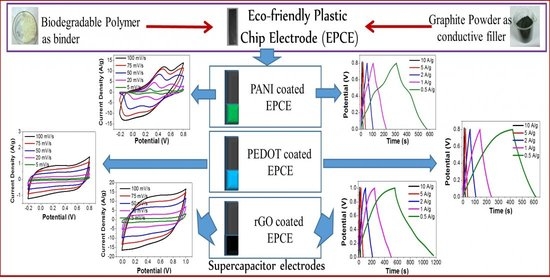
A Biodegradable Polymer-Based Plastic Chip Electrode as a Current Collector in Supercapacitor Application

1
Analytical and Environmental Science Division & CIF, CSIR-Central Salt & Marine Chemicals Research Institute, G.B. Marg, Bhavnagar 364002, India
2
Academy of Scientific and Innovative Research (AcSIR), Ghaziabad 201002, Uttar Pradesh, India
*
Author to whom correspondence should be addressed.
Electrochem 2022, 3(3), 379-396; https://doi.org/10.3390/electrochem3030026
Submission received: 1 June 2022 / Revised: 24 June 2022 / Accepted: 28 June 2022 / Published: 7 July 2022
(This article belongs to the Special Issue Feature Papers in Electrochemistry)

Abstract

:
Here, we report the performance of a biodegradable polymer-based Plastic chip Electrode (PCE) as a current collector in supercapacitor applications. Its production was evaluated using two redox materials (conducting polymers polyaniline and poly(3,4-ethylene dioxythiophene)) and a layered material, rGO. The conducting polymers were directly deposited over the Eco-friendly PCE (EPCE) using the galvanostatic method. The rGO was prepared in the conventional way and loaded over the EPCE using a binder. Both conducting polymers and rGO showed proper specific capacitance compared to previous studies with regular current collectors. Electrodes were found highly stable during experiments in high acidic medium. The supercapacitive performance was evaluated with cyclic voltammetry, charge–discharge measurements, and impedance spectroscopy. The supercapacitive materials were also characterized for their electrical and microscopic properties. Polyaniline and PEDOT were deposited over EPCEs showing >150 Fg−1 and >120 Fg−1 specific capacitance, respectively, at 0.5 Ag−1. rGO continued to show higher particular capacitance of >250 Fg−1 with excellent charge–discharge cyclic stability. The study concludes that EPCs can be used as promising electrodes for electrical energy storage applications.

Graphical Abstract

1. Introduction

Energy storage is a fascinating topic among electrochemists and the scientific community [1,2]. Great interest has been driven towards developing more efficient energy storage devices [3,4,5]. Electrochemical capacitors (EC) or pseudocapacitors, have been vigorously investigated as a potential energy storage solution with several systems where sustainability is a significant concern [6,7]. Many conducting polymers such as polythiophene, polypyrrole, PEDOT, and polyaniline, etc., are used for energy storage applications [8,9]. Amongst these polymers, polyaniline and PEDOT are promising candidates due to the ease of their electrochemical synthesis directly over the electrode surface [10,11]. Polyaniline [12] and PEDOT [13] can be grown very easily by different electrochemical techniques such as galvanostatic, potentiostatic, and potentiodynamic. After electro-synthesis, their adhesion with current collectors is generally extreme, as conducting polymers form short films over the electrodes [14]. On the other hand, rGO carbon nanomaterial is an excellent material due to its conductivity and high surface area, high supercapacitive performance, and high charge–discharge cyclic stability. Chemically prepared rGO is deposited over current collectors by coating, along with suitable binders. So, the choice of collectors is crucial for these supercapacitive applications [15].
Current collectors play a central role in any supercapacitor device. Electrodeposition of high surface area conductive materials over these current collectors and there use for further tasks is also essential. Many current collectors are reported in the literature, such as carbon fabrics [16], polymer films with conductive coatings [17], metal foils such as Aluminum and Nickel foils [18,19], Nickel foams [20] and stainless-steel fabrics [21]. Carbon fabrics are flexible and mechanically robust but not cost-effective. Polymer films with conductive coatings of CNT, graphene, or other conductive material are good options, but these coatings can be delaminated to expose the non-conductive surface. Metal foils are rigid or flexible in nature but are not stable in anodic potentials in acidic, as well as a primary medium, because, in liquid electrolytes, these metals become oxidized, leading to corrosion over time [22]. Furthermore, these metallic fabrics are not environmentally friendly. Regarding Nickel foams, their properties are similar to Nickel-metal, and anodic potentials cannot be applied, so, generally, electrochemical measurements can be carried out at cathode potentials only. Stainless steel fabrics are excellent and used by many researchers due to their superior conductivity, mechanical strength, and acid or base neutrality. However, they are still unsuitable at high anodic potentials in liquid systems and are not eco-friendly. Moreover, most of the research in this area has focused on protecting stainless-steel from corrosion by coating the conducting polymers. So, an easily synthesizable, flexible, cost-effective, and nature-friendly current collector can play a better role in the direct deposition of conducting polymers without a binder, and these assemblies could be very useful for supercapacitor applications. Materials such as rGO can also be bounded with these current collectors using adhesives. Graphite plates and rods are extensively used as electrode surfaces for electrochemical reactions to occur, e.g., polyaniline electro-synthesis [11]. However, these plated and pencil graphite electrodes are not flexible in nature, can be substantial in weight (could make not portable devices), and are sometimes not cost-effective. Graphite is a stable material with broader potential window. We can make this current collector rigid or flexible by choosing different aliphatic polyesters. After solution casting, some polyesters form rigid films but some that are flexible form films, depending on the nature of the polymer. Polylactic acid (PLA) builds rigid films [23,24]. In our previous work, a solution casting method was demonstrated to prepare a plastic chip electrode where conventional polymers were used [25]. Choosing the biodegradable polymers can add extra benefit to this type of current collector, which makes it environmentally friendly.
Polyaniline grows on conductive substrates at anodic potential in a highly acidic medium, and polymer/graphite composites chip electrodes could be good candidates for it. Many types of research have been devoted to the synthesis of conducting polymers or their composites by chemical methods and further coated over current collectors using some binders. Reports on electrochemically grown polyaniline and PEDOT are limited to energy storage applications in combination with low cost, bulk conducting, and current eco-friendly collectors. Although rGO coating using a binder over the current collector is easy and cost-effective, its electrochemical testing requires conventional high-cost inert electrodes such as glassy carbon electrodes and inert metal electrodes. So, carbon-based rigid or flexible, low cost, easily fabricable electrodes are needed, which can be stable in electrochemical supercapacitor applications.
Herein, we report the electro-synthesis of polyaniline and PEDOT over polymer/graphite chip electrodes to be used in supercapacitor applications in an aqueous system. rGO is prepared using chemical methods and studied alongside current collector electrodes. Here, we used a polylactic acid (PLA) polymer as the matrix material and graphite filler as a conductive material to form self-standing, conductive, and mechanically robust polymer/graphite chip electrodes as current collectors. These chip electrodes are cost-effective. The biodegradability of the PLA is well known. A graphite surface can be established for the electropolymerization of polyaniline and has better adhesion over the surface. So, graphite powder can be chosen as a filler. The acid resistance and insolubility of these polymers in water and the electrochemical inactivity of graphite furnish these EPCEs (Eco-friendly plastic chip electrodes) as the right candidates for aqueous systems.

2. Experimental

2.1. Materials and Methods

For EPC’s preparation, Graphite powder (referred to as G1 in this paper) (CDH Pvt. Ltd., Dahej, Gujarat, India) was used as the conductive material (filler). A commercial-grade biodegradable polymer PLA was used in this work. This was produced and supplied by Nature works (USA) as semi-crystalline pellets with the commercial name, 3051D. This grade of PLA is a random copolymer, poly(L-lactide-co-meso-lactide), with approximately 3.3% D-lactide content. Chloroform (s.d. fine chem) of AR Grade was used to dissolve PLA. Aniline was purchased from Sigma-Aldrich and stored in the refrigerator after double distillation. EDOT was also received from Sigma-Aldrich and stored in the fridge below 5 °C. Two types of graphite powder obtained from CDH chemicals and Sigma-Aldrich were used to make graphene oxide to determine the difference in both precursors. KMnO4, NaNO3, and H2O2 (30%) were obtained from s.d.fine chemicals and used as received. Graphite powder was purchased from CDH (particle size is 50 µm) and Sigma-Aldrich (particle size is <150 µm). The 50 µm sized graphite is referred to as G1 (as shown above), whereas <150 µm sized graphite is referred to as G2. Both G1 and G2 graphites were used for the synthesis of graphene oxides. H2SO4 and KCl (SRL chemicals) were used to make electrolyte solutions for electrochemical analysis. All other chemicals used were of AR grade.

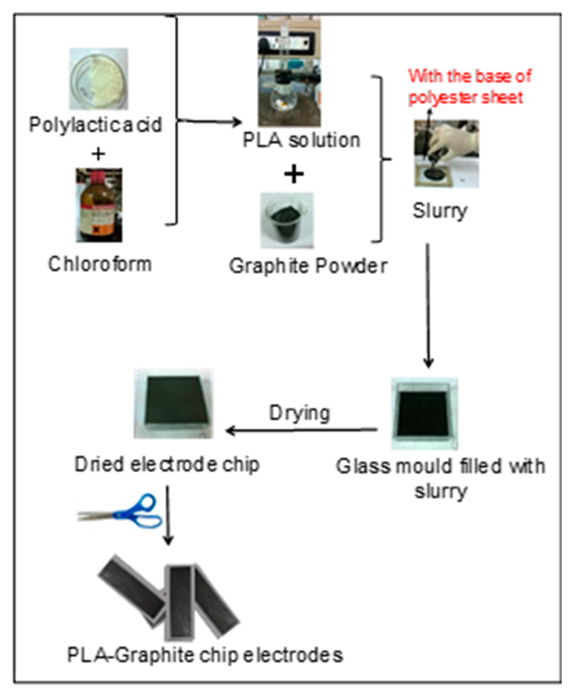
2.2. Preparation of EPCEs of PLA-Graphite (PLAGr)

The solution casting method was employed to make EPC’s. The preparative steps are shown for PLAGr composites in Figure 1, respectively. For PLAGr, nine different compositions were prepared by varying the ratio of the components from 10% to 90%. For this purpose, 10% w/v of PLA solution in chloroform was used. A total of 200 mL of this solution was prepared. Nine glass molds in a square shape made with glass slides were used for solution casting purposes. The area of all glass molds was 7.2 cm × 7.5 cm (54 cm2). The base of the molds was covered with a polyester sheet (the polyester sheet was insoluble in chloroform). To produce homogenized suspension of graphite in PLA solution, it was sonicated in n aultra sonicator and stirred with a glass rod for 10 min. Prepared slurries were poured in these molds and covered with a thin paper during evaporation. This facilitates the slow rate of evaporation of the organic solvent to make good quality chips. This assembly was left for around 24 h at room temperature for evaporation of the solvent and to make chips. These chips were peeled off from the polyester sheet. Used amounts of the materials to prepare PLAGr composites with different compositions are tabulated in Table S1 (ESI).
Dried chips were stored in airtight plastic pouches. These EPCs were cut into a specific dimension for application as current collectors in electrochemical experiments. Only one type of ratio of EPCE (Polymer 40% and Graphite 60%) was applied as current collectors in the supercapacitor study, and the purpose in choosing this composition is described in the results and discussion section (bulk conductivity).

2.3. Spectroscopic and Morphological Characterizations

The Fourier transformed infrared (FT-IR) spectra of graphene oxide (GO) and rGO samples were recorded on a Perkin-Elmer Spectrum GX (FT-IR System, Akron, OH, USA. 520 S) instrument by preparing KBr pellets in the range of 400–4000 cm−1. Powder X-ray diffraction (XRD) measurements of the GO, rGO, and graphite powder samples were recorded on the PANalytical powder X-ray Diffractometer using Cu-Kα (λ = 0.15406 nm) radiation. The morphology of PANI-coated, PEDOT-coated EPCEs and prepared GO nanosheets were evaluated with a field emission scanning electron microscopy FE-SEM (model JEOL JSM 7100F) at an acceleration voltage of 15 kV. For TEM analysis, GO samples were prepared by dispersing a small number of samples in THF. Then, one drop of the suspension was dropped on 300 mesh copper (lacey carbon coated) TEM grids. The microstructures of GO and rGO were determined using LabRAM HR Evolution RAMAN SPECTROMETER (HORIBA Scientific) at a frequency of 488 nm. Thermogravimetric analysis (TGA) to determine thermal stability was carried out using Model TG209F1Libra (NETZSCH, Germany) at a heating rate of 10 °C/min under nitrogen flow from room temperature to 800 °C for GO and rGO samples. The conductivity of GO and rGO in pressed pellet form was measured using the source meter unit Keithley (Model 2635A) Instrument. It integrates a digital multimeter, power supply, current source, electronic load, and pulse generator all into one compact, tightly synchronized instrument. The conductivity of different compositions of PLAGr and PCLGr was recorded by sandwiching the square-sized (1 cm × 1 cm) chips between two platinum electrodes in the spring-loaded sample holder, and by applying voltage, the current is measured. The experiment in this study was repeated up to four times to determine the reproducibility of the materials; the results remained the same.

2.4. Electrochemical Deposition of PANI on PLA4Gr6 (PLA4Gr6/PANI) Electrodes

The schematic procedure of galvanostatic deposition or coating over PLA4Gr6 is shown in Figure S1a (ESI). The galvanostatic coating of PANI has been applied in previous works [26,27]. Here, we applied suitable current density (0.5 mAcm−2) in acidic solution. First, 0.1 M aniline monomer prepared in 1 M H2SO4 was used to deposit polyaniline on the electrode surface. In the three-electrode electrochemical assembly, the area of working electrode was set to 1 cm2. Ag/AgCl (sat. KCl) and platinum foil were used as a reference and counter electrodes, respectively. The scheme of the assembly is shown in Figure S1a (ESI). Polymerization was conducted in a beaker filled with 10 mL of monomer solution at a galvanostatic current density of 0.5 mAcm−2 for 15 min. Galvanostatic polymerization curves are shown in Figure S1b (ESI) for PLA4Gr6 working electrodes, respectively. After polymerization, the working electrodes were washed with de-ionized in water and then dried in an oven at 55 °C for 12 h. The resultant electrodes are defined as PLA4Gr6/PANI. Deposited material weight (PANI weight) was recorded by analytical balance (precise to four decimal places) by subtracting the bare working electrode weight from the PANI-coated electrode weight. Within 15 min., almost 1 mg of PANI weight was deposited on these electrodes, and many samples were prepared in the study. These weight values (exact values of some samples are given in Table S2, (ESI) were used further to calculate specific capacitance.

2.5. Electrochemical Deposition of PEDOT on PLA4Gr6 (PLA4Gr6/PEDOT) Electrodes

A schematic of PEDOT electrochemical coating over PLA4Gr6 electrodes is shown in Figure S2a (ESI), and its potentiostatic polymerization curve is shown in Figure S2b (ESI). PEDOT was deposited on PLA4Gr6 electrodes by potentiostatic polymerization by applying 1.2 V potential for 10 min in 0.1 M EDOT monomer prepared in 0.1 M KCl electrolyte. Again, the same procedure of drying and weighing was applied for this as for PANI. The weight of the deposited PEDOT is also given in Table S2 (ESI).
rGO was coated on PLA4Gr6 electrodes by coating the paste of rGO (85%), Acetylene black (5%), and PTFE (Nafion) (10%) over a 1 cm2 area of the electrode with the help of a brush. After loading the electroactive paste, the electrode was dried in an oven at 60 °C for 12 h before the electrochemical testing. After complete drying, the total weight of the coating material was 0.9 mg (here rGO weight is 0.8 mg, Table S2, given in ESI) and electrochemical experiments were performed on 1 M H2SO4 electrolyte. The detailed synthetic procedure of GOs from graphite (G1 and G2) and further rGO preparation details are given in the upcoming sections.

2.6. Electrochemical Characterizations for Supercapacitive Electrodes

Electrochemical measurements of PANI-coated electrodes and rGO coated electrodes were carried out using the three-electrode system in 1 M H2SO4 electrolyte. For PEDOT-coated electrodes, the electrolyte was 0.2 M KCl. A platinum foil and Ag/AgCl (sat. KCl) electrodes were used as the counter and the reference electrodes, respectively. For electrochemical testing Cyclic voltammetry (CV), galvanostatic charge–discharge (GCD) was recorded on potentiostat/galvanostat (Autolab PGSTAT 204), and electrochemical impedance spectroscopy (EIS) was carried out on the PARSTAT Model 2273 with a built-in frequency response analyzer, at room temperature under ambient conditions, over the frequency range of 20 kHz to 100 mHz, with a sinusoidal voltage amplitude of 10 mV superimposed on 0 V DC (vs. open circuit).Cyclic voltammetry measurements were carried out in the potential range of −0.2 to 0.8 V vs. Ag/AgCl (sat. KCl) for PANI, PEDOT-coated electrodes and 0.0 to 1.0 V for rGO-coated electrodes by varying the scan rate from 5 mVs−1 to 100 mVs−1. Galvanostatic Charge–discharge measurements were carried out with a constant current at 0.5, 1, 2, 5, and 10 Ag−1 in a potential window of 0.0 to 0.8 V for PANI, PEDOT, and rGO; it was 0.0 to 1.0 V.

2.7. Synthesis of Graphene Oxides (GO), Their Purification and Reduction to rGO (Reduced Graphene Oxide)

Hummers modified method [28] was used to prepare graphene oxides of good quality. Details of the procedure are given in the electronic supplementary information with a reduction in obtained GO.

3. Results

3.1. Bulk Conductivity of Different Compositions of PLAGr

The obtained I-V plots and the results of bulk conductivity of various compositions of PLAGr are shown in Figure 2 and Table 1. I-V plots (Figure 2a) of all the samples were linear in the voltage window of ±5 V, indicating the ohmic nature of the material. It was found that the bulk conductivity increased steadily as graphite content increased up to 50 wt.%, which is clear from Figure 2b, where the percolation threshold achieving point is shown. The detailed numerical data of various compositions are compiled in Table 1. As can be seen, conductivity increases as graphite percentage increases. After 50 wt.% of graphite filler, further increment in conductivity is negligible. Such large variations in the values of conductivity occurring in the range of the graphite content from 40 wt.% to 50 wt.% indicate that the phenomenon of percolation appears in the studied samples at 50 wt.% ratio. So, 50–60% graphite containing electrodes can demonstrate good performance in PLAGr composite electrodes in electrochemical experiments.
According to the percolation theory, 60 wt.% graphite content in a composite demonstrates good percolation and enough conductivity. So, the PLA4Gr6 sample was further studied in the electrochemical application.

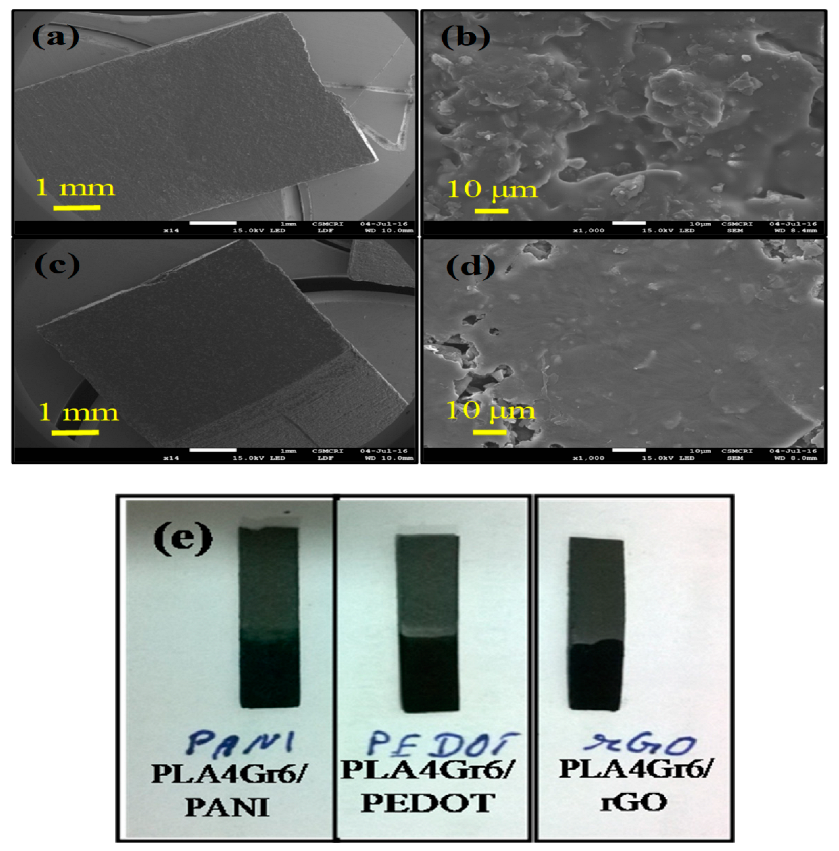
3.2. Scanning Electron Microscopy of PANI and PEDOT Coated Polymer/Graphite Chip Electrodes

The SEM micrographs of the samples coated with PANI and PEDOT on PLA4Gr6 are shown in Figure 3. Figure 3a,c are at lower magnification, and Figure 3b,d are at higher magnification images. The micrographs suggest that the coating of the conducting polymers is smooth and homogeneous. At higher magnifications, some granular parts are also visible. These are the nucleus that formed during the initiation of polymerization, which can be observed in the chronopotentiometry plot during polymerization of PANI (Figure S1c,d) (ESI). At the onset of polymerization, potential was high, being around 0.8 V, but after some time, it decreased to approximately 0.7 V [29]. The initial potential surge was attributed to the nucleation process of PANI, then it dropped down during the propagation stage. Photographs of coated electrodes are also shown in Figure 3e.

3.3. XRD, Raman, SEM, TEM, TGA, FT-IR Characterizations of Prepared GO1 and GO2

3.3.1. XRD of Graphite, GO1, and GO2

The XRD pattern of graphite is straightforward, and only one peak exists in its natural state. Here, in Figure S5a (ESI), the XRD pattern of G2 is shown. This one peak in the XRD pattern has an intensity maximum of around 2θ = 26.46° (002 planes). During the oxidation process, this peak disappears, and another peak appears, which has an intensity maximum of around 2θ = 10° (001 planes) for both samples GO1 and GO2. During the oxidation process, graphite sheets that are bound tightly in graphite powder particles react with oxygen atoms provided by the potassium permanganate, and therefore the distance between the layers increased. So, the change in the single peak of graphite from 2θ = 26.46° to around 10° (9.17° for GO1 and 8.07° for GO2) can be seen for both samples. Apart from the maximum of 2θ = 10°, an additional minor peak was observed around 2θ = 18° (18.18° for GO1 and 17.35° for GO2). As can be seen in Figure S5b (ESI), the absence of a peak at 2θ = 26.46° indicates that graphite powder (starting material) is absent in both purified GO samples. The interlayer spacing of the materials is proportional to the degree of oxidation. Corresponding d spacing values for GO1 and GO2 were calculated to be around 9.6 Å and 10.9 Å, respectively.

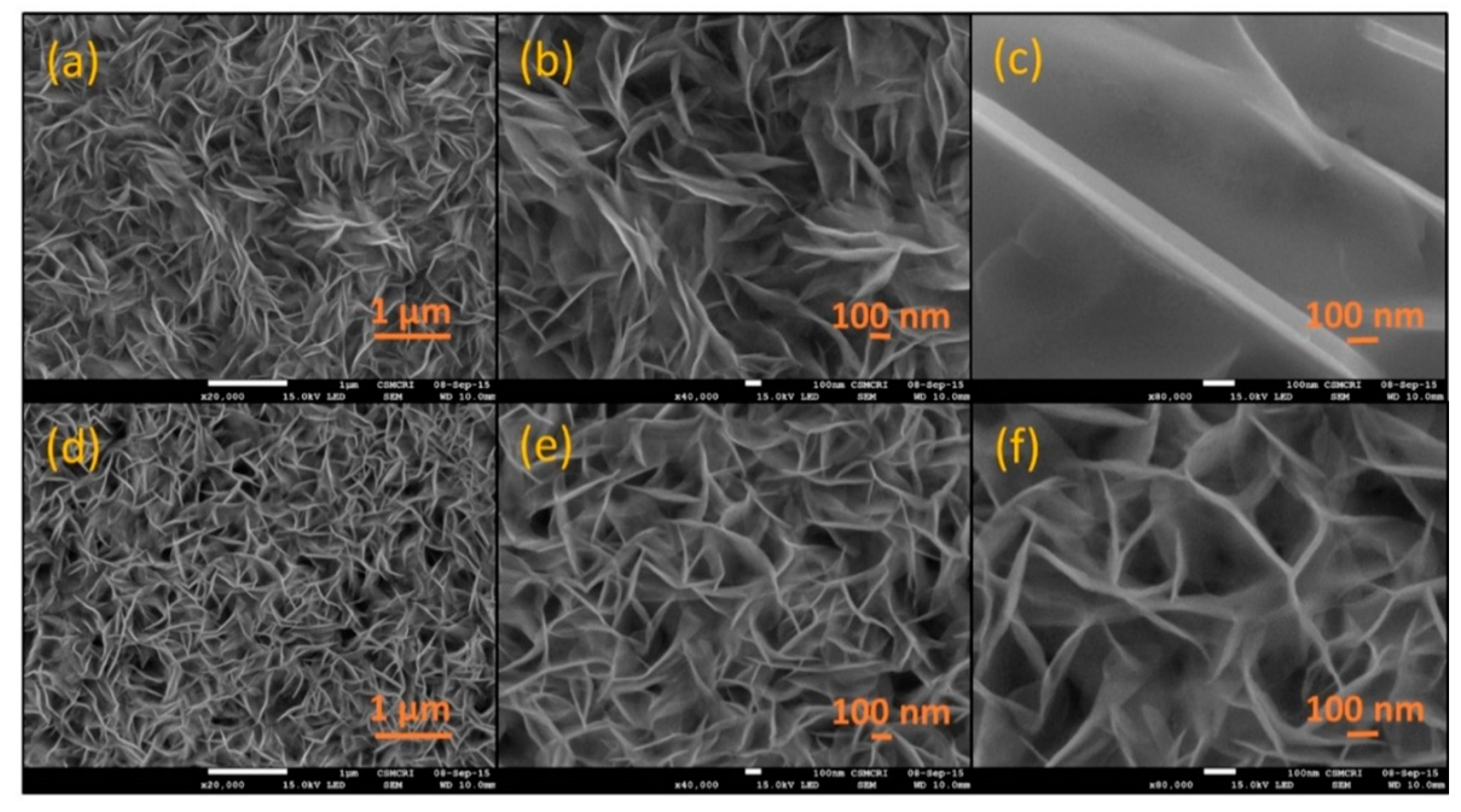
3.3.2. Scanning Electron Microscopy

The FE-SEM micrographs of synthesized GO at different magnification levels (20 Kx, 40 Kx, and 80 Kx) are given in Figure 4. Exfoliation of Graphite chunks using the modified hummers process converts it into layered small-sized flakes of GO. The stacking of GO sheets is clearly visible in all FE-SEM images. FE-SEM images of the Graphene Oxide (GO) have well-defined and interlinked three-dimensional Grapheneoxide sheets that form a porous network that resembles a loose sponge-like structure for both samples. Figure 4a–c [GO1] and Figure 4d–f [GO2] show that graphene oxide prepared from both the graphite (G1 and G2) have similar morphologies [30].

3.3.3. Raman Spectroscopy

The prepared GO2 were further characterized by Raman spectroscopy which allowed us to consider the conjugated and carbon–carbon double bonds, which leads to high intensity peak in the Raman spectra. The typical Raman spectra of GO2 is characterized by a G band at ~1578 cm−1, which corresponds to E2g phonon of the sp2 C atoms and a weak band at ~1347 cm−1 (D band), which corresponds to the breathing mode of κ- point phonons of A1g symmetry and the 2D band around 2800 cm−1. The D band is an indication of disorder, which may arise from certain defects such as vacancies, grain boundaries and amorphous carbon species. GO2 (obtained from G2) data are shown in Figure S6 (ESI).

3.3.4. Thermogravimetric Analysis

Graphite is a rather thermally stable substance with a decomposition temperature of ca 600 °C in comparison to GO, which has a decomposition temperature of ca 200 °C. This difference is due to the oxygen atoms that have been added to the sheets in the GO. TGA was carried out in a temperature range from room temperature to 1000 °C in dynamic mode at 10 °C/min in a nitrogen environment. For both samples GO1 and GO2, weight loss was almost similar, confirming the almost same extent of oxidation of graphite powders. In Figure S7 (ESI), it can be seen that the materials have a weight loss (~9%) below 100 °C due to loss of adsorbed water from both samples and significant weight losses (~35%) between 150 °C and 250 °C, which corresponds to CO, CO2, and steam release from the most labile functional groups [31]. Steady weight loss (~11%) over a temperature range between 250 °C and 1000 °C may be attributed to the removal of more stable oxygen functionalities [32]. At 1000 °C, 40% residual mass is left, as is clear from the TGA curves. So TGA confirms the formation of graphene oxide.

3.3.5. Transmission Electron Microscopy

TEM analysis was also carried out study morphology at higher magnifications and crystallographic studies of sample GO1 and GO2. TEM samples were prepared by placing a drop of graphene oxide dispersion (in THF) on a lacey carbon-coated copper grid and subsequently evaporating the solvent. The transparency of the flacks indicates the ultrathin nature of the GO film, which is possible through severe exfoliation of the graphite only. Figure S8a–d (ESI) are images of GO1 and Figure S8e–h (ESI) are of GO2. The dot pattern in the electron diffraction (SAED) (Figure S8i) (ESI) shows the hexagonal structure of the GO2 with the AB stacking, as expected, which resembles it with the graphitic skeleton [33]. The diffused nature of the diffraction pattern indicates the somewhat amorphous structure of the obtained graphene oxide, due to the great extent of oxidation of graphite powder.

3.3.6. FT-IR Spectroscopy

The FT-IR spectra of GO1 and GO2 nanosheets are depicted in Figure S9 (ESI). Oxygen-containing groups can be seen, in which the main absorption band at 3416 cm−1 for both samples are assigned to the O-H group stretching vibrations. The absorption peak at 1737 cm−1 is assigned to C=O stretching of carboxylic functional groups. Additionally, 1630 cm−1 can be assigned to C=C from unoxidized sp2carbon carbon bonds. The two absorption peaks at about 1229 cm−1 and 1055 cm−1 are attached to the C-O stretching vibrations. FT-IR of both GO1 and GO2 indicated that both materials were similar in chemical composition.
So, all these characterizations confirm that graphene oxide is formed with good quality. Overall obtained graphene oxides from G1 and G2 are similar in class, and anyone of these two can be used to produce good quality GOs. We can use any of them to convert in rGO for further supercapacitor applications (conversion to rGO is described earlier in the experimental section). Here, only GO2 is are used for reduction to prepare rGO and for electrochemical studies.

3.4. XRD, Raman, TGA, FT-IR and Electrical Conductivity Characterizations of rGO

The rGO sample was characterized using X-ray diffraction (XRD) and Raman spectra to evaluate the surface nature. XRD pattern of rGO in Figure 5a shows the presence of a broad peak in the range of 23–26° (002 planes), which may be attributed to the short-range ordering in the stacks of rGO. Therefore, the disappearance of the peak at 10.9° confirms the reduction in GO2. Furthermore, Raman spectral analysis for rGO in Figure 5c confirms the decrease in GO2 to rGO. Significant structural changes occurred during the chemical processing to obtain rGO. rGO Raman spectrum consists of a D-band at 1340 cm−1 and a G-band at 1570 cm−1, but the 2D-band disappeared, which was visible in GO2. Additionally, the D-band becomes prominent, which indicates the reduction in the size of the in-plane sp2 domains, possibly due to extensive oxidation. Compared to GO2 here, rGO showed an increased D/G intensity ratio, which suggests a decrease in the average size of the sp2 domains upon the reduction in exfoliated graphene oxide [34].
FT-IR spectrum (Figure 5b) confirms the absence of oxygen-containing functional groups in rGO. This is evident from the disappearance of many prominent peaks of the GO2 FT-IR spectrum in rGO. Some residual peaks indicate the presence of less oxygen-containing groups. A broad peak was obtained in GO2 at 3416 cm−1, which was completely lost in the spectrum of rGO. Peaks at 1737 cm−1 and 1630 cm−1 were also lost in rGO. Sharp spikes in the GO2 in the region of 1050–1230 cm−1 decreased to residuals.
The TGA plot of rGO is given in Figure S10a (ESI). It is evident from this plot that rGO is much more thermally stable than GO2. The removal of the thermally labile oxygen functional groups by the chemical reduction process attributed to this increased thermal stability, which is analogous to graphite. Apart from a slight mass loss below 200 °C, which can be attributed to the loss of adsorbed water, no significant weight loss was observed to 800 °C.
The electrical conductivity of rGO depends on the extent of the reduction in graphene oxide. Graphene oxide is inherently non-conductive because there are no percolation pathways between sp2 carbon clusters, which is indeed a career transport mechanism in graphene. Graphene oxide has large chemical functional groups attached to the carbon plane with several defects within the plane, both of which severely decrease the electrical conductivity. However, it can be restored by the thermal reduction route. As reduction proceeds, conductivity increases. The reduction process eliminates the epoxy and hydroxyl group on the plane, while retaining other groups [35]. The electrical conductivity of the GO2 and rGO powders was measured on their compressed pellet forms. For this purpose, 100 mg of the material was used to make pellets by applying 5-ton pressure using a hydraulic press. The I-V measurements were carried out by the two-probe method, and DC conductance was calculated from the slope of the I-V curve. It is clear from Figure S10b (ESI) that the conductivity of rGO is much larger than GO2. Calculated electrical conductivity of the GO2 sample was 9.09 × 10⁻³ mS cm−1, and for the rGO sample, it was 54.38 mS cm−1.
This characterization confirms the almost complete reduction in GO2 to rGO. The majority of oxygen-containing functional groups have been found to be removed during the reduction process. Increased electrical conductance and thermal stability can be expected due to this, resulting in enhanced supercapacitive behavior.

3.5. Electrochemical Studies of Supercapacitor Electrodes

3.5.1. PANI on Polylactic Acid-Graphite Chip Electrode (PLA4Gr6/PANI)

The charge–discharge characteristics of the supercapacitor were tested by potentiodynamic cycling for PLA4Gr6/PANI electrodes in 1 M H2SO4 at various scan rates in the three-electrode configuration. The corresponding cyclic voltammogram is shown in Figure 6a, which exhibits large rectangular loops with two oxidation and two reduction peaks. The peaks are identified as redox peaks for leucoemeraldine/emeraldine and emeraldine/pernigraniline states of the PANI film [36]. As the scan rate was increased, the current response, which is a measure of the capacitance, increased. The similar shape of the CV curves recorded at different scan rates indicates the excellent redox reversibility of the PANI films over PLA4Gr6 electrodes. The charge–discharge characteristics have also been tested by Galvanostatic mode in the three-electrode configuration. Figure 6b shows the charging–discharging curves recorded in the cut-off voltage range from 0.0 V to 0.8 V (versus Ag/AgCl) at five different applied current densities. Charge–discharge curves possess non-linear potential characteristics during the process, which is due to the redox behavior of PANI. The specific capacitances were calculated from the charge–discharge curves using the following Equation (1) [37].
C = I∆t/m∆V
where I is the charge–discharge current, Δt is the discharge time, ΔV is the electrochemical potential window, and m is the mass of the electroactive material. Specific capacitances calculated at current densities of 0.5 Ag−1, 1 Ag−1, 2 Ag−1, 5 Ag−1 and 10 Ag−1 were 170 Fg−1, 146 Fg−1, 132 Fg−1, 125 Fg−1 and 116 Fg−1, respectively, as shown in Figure 6c. The specific capacitance values calculated by (potentiodynamic and galvanostatic) charge–discharge methods are almost the same. It was also observed that the polymer synthesis condition also plays an important role in the performance of supercapacitors. The literature review revealed that the specific capacitance values of the PANI synthesized by the galvanostatic technique in this study have higher, or at least equal, values [12]. Although these values are still lesser than the values, as obtained by other techniques such as chemical and potentiodynamic techniques. It is known that the potentiodynamic technique produces more porous morphology in PANI and, hence, can store more charge. The lesser value, as obtained in the case of galvanostatic polymerization, is attributed to this fact [12,38,39]. For practical applications of these supercapacitors, the higher number of charge–discharge cycles is required. Charge–discharge was carried out continuously for 1000 cycles. The starting ten cycles of charge–discharge of the PLA4Gr6/PANI electrode within a potential cut-off window of 0.0 to 0.8 V at a constant current density of 10 Ag−1 is shown in Figure 6d. It repeats itself in the same way during the charge–discharge process, which indicates that it has good charge–discharge reversibility. Figure 6e shows the measured specific capacitances of the electrode for 1000 cycles. The capacitance values were initially found to decrease till 150 cycles and then subsequently become stable. A 45% capacitance loss occurred during the initial 150 cycles, then around a10% loss was observed till the 1000th cycle. At 1000th cycle, capacity retention was 45%. The Nyquist impedance plot (AC impedance) of the electrode recorded in 1 M H2SO4 is shown in Figure 6f. A small semicircle (shown in the inset of the figure) can be observed in the higher frequency region. The semicircle corresponds to the parallel combination of resistance and capacitance, whereas the inclined line in the low-frequency region corresponds to Warburg impedance. The phase angle between current and voltage for all samples on the few selected frequencies is given in Table 2. It can be seen in the table that the phase angle is close to 90° at a lower frequency, which decreases towards 0° as the frequency increases. This result indicates that the electrode behaves resistive at high frequency and capacitive at low frequency, as supercapacitors generally show [40]. An intercept can also be seen on the real axis of the impedance plot, measuring around 10 ohms. This pure resistive component corresponds to solution resistance and electrical connections in the circuit.

3.5.2. PEDOT on Polylactic Acid-Graphite Chip Electrodes (PLA4Gr6/PEDOT)

PEDOT electrochemically deposited (without binder) on PLA4Gr6 electrodes by potentiostatic polymerization was tested for its supercapacitive performance. The charge–discharge characteristics of the electrode were tested by potentiodynamic cycling in 0.2 M KCl electrolyte at various scan rates. The corresponding cyclic voltammograms are shown in Figure 7a. With current-voltage waves, it can be seen that curves have a nearly rectangular shape, which is typical of the EDLC behavior of the material [41]. The charge–discharge performance has also been tested by galvanostatic mode. The galvanostatic charge–discharge curves of the PLA4Gr6/PEDOT within a potential cut-off window of 0.0 to 0.8 V (versus Ag/AgCl) at various constant current densities are shown in Figure 7b. High specific capacitance was obtained for PEDOT. Specific capacitance calculated at current densities of 0.5 Ag−1, 1 Ag−1, 2 Ag−1, 5 Ag−1 and 10 Ag−1 were 128 Fg−1, 120 Fg−1, 115 Fg−1, 97 Fg−1 and 91 Fg−1, respectively (Figure 7c). The multiple cycle charge–discharge curve of the PLA4Gr6/PEDOT electrode within a potential cut-off window of 0.0 to 0.8 V at a constant current density of 10 Ag−1 is shown in Figure 7d. It behaves as a triangular profile during the charge–discharge process, which indicates that this material has good charge–discharge reversibility. Long term charge–discharge cycle stability of conducting polymers is important to consider for super applications. To test the charge–discharge cycle life of PEDOT, consecutive charge–discharge scans were performed in a 0.2 M KCl solution at 10 Ag−1 current density. Figure 7e depicts that the specific capacitance of the polymer changed along with the cycles. A total of 1000 charge–discharge cycles were run, and at the 1000th cycle, the capacity retention was 80%. The higher capacity retention of PEDOT compared to Polyaniline may be credited to the better mechanical strength of PEDOT during charging and discharging. The electrochemical impedance spectrum of PEDOT to see the relationship between real (Zreal) and imaginary (Zimg) impedance components of PEDOT for a frequency range of 20 kHz to 100 mHz is displayed in Figure 7f. The Nyquist plot is composed of a tiny semicircle part (inset, Figure 7f) at high frequency and a 45° capacitive slope at low and middle frequencies. The semicircle at low frequency is due to charge transfer resistance, which originates from the interface between the porous electrode surface and the electrolyte. The inclined part of the plot is due to the diffusion limitation in the doping/undoing process [42]. At middle and low frequencies, the impedance plot becomes a near-vertical line, which is indicative of a redox layer produced by the ac stimulation penetrating the entire depth of the polymer film [43]. The phase angle between current and voltage on a few selected frequencies is given in Table 2. An intercept can also be seen on the real axis of the impedance plot, measuring around 22.8 ohms, which is due to solution resistance and electrical connections in the circuit. The obtained value of specific capacitance (128 F·g−1) of PEDOT in this work is comparable to or greater than reported in the literature [44,45,46,47].

3.5.3. rGO Coated PLA4Gr6 Electrodes (PLA4Gr6/rGO)

High electrically conductive rGO coated on PLA4Gr6 electrodes was electrochemically tested for its supercapacitive performance by potentiodynamic cycling, galvanostatic charge–discharge, and EIS in 1 M H2SO4 electrolyte with three-electrode configuration. Cyclic voltammograms (Figure 8a) were recorded in the potential range of 0.0 V to 1.0 V at different scan rates from 5 mVs−1 to 100 mV.s−1. These CVs show the electric double layer capacitance (EDLC) behavior of PLA4Gr6/rGO electrode. Figure 8b shows Galvanostatic charge–discharge curves recorded in the cut-off voltage range of 0.0 V to 1.0 V (versus Ag/AgCl) at five different applied current densities. A good specific capacitance was obtained for this material. Specific capacitance calculated at current densities of 0.5 Ag−1, 1 Ag−1, 2 Ag−1, 5 Ag−1 and 10 Ag−1 were 289 Fg−1, 257 Fg−1, 224 Fg−1, 170 Fg−1 and 137 Fg−1, respectively, as shown in Figure 8c. At 0.5 Ag−1 current density, the specific capacitance value is double than calculated for 10 Ag−1. This means at the lower value of current density, electrolyte interaction or diffusion into the pores of rGO is twice as more efficient, which is due to slow and more efficient diffusion of electrolyte into pores of the material. To demonstrate the charge–discharge cycle life performance and to support electrode-electrolyte structure, 1000 cycles were run at 10 Ag−1 current density. The initial 10 cycles of galvanostatic charge–discharge are shown in Figure 8d, where it is clear that charging and discharging are repeating alternatively at a fix time interval, which confirms the good and continuous charge–discharge behavior of the material. Specific capacitance and capacity retention (%) v/s charge–discharge cycle number plots are given in Figure 8e. It is clear from the figure that the system retains a high specific capacitance; even till the 1000th cycle, no loss of specific capacitance is observed. This may be credited to the relatively large surface area of the electrode with excellent electrical conductivity and good mechanical strength of rGO. Electrochemical impedance spectroscopy (EIS) was also performed with the electrode, and the Nyquist plot is shown in Figure 8f. The Nyquist plot exhibits a small semicircle in the high-frequency region followed by an inclined line in the low-frequency region. The straight line at the low frequency of the Nyquist plots is the Warburg resistance, confirming near-ideal capacitor response. Warburg resistance is generated by the interruptions in the sample uniformity during the diffusion process, i.e., during the semi-infinite diffusion of ions into the porous structure. The ion diffusion path can be predicted by following the trends of larger Warburg resistance, which indicates greater variations in ion diffusion path lengths and increases the hindrance of ion movement [45]. The phase angle between current and voltage on a few selected frequencies are given in Table 2. An intercept can also be seen on the real axis of the impedance plot, measuring around 10 ohms, which is due to solution resistance and electrical connections in the circuit.
After discussing the supercapacitive behavior of the four systems, it is necessary to determine the current collectors’ electrochemical reaction in a bare form (without the coating of supercapacitive material). Nyquist impedance plots of PLA4Gr6 and PCL4Gr6 electrodes in 1 M H2SO4 solution with the same frequency range are shown in Figure S12 (ESI). For the PLA4Gr6 electrode, the semicircle part is evident in the high-frequency region and inclined part in the low-frequency region. Here, the semicircle is significant due to the resistance at the electrode–electrolyte interface, and electrolyte diffusion cannot happen into the electrode non-porous material. In the case of the PCL4Gr6 electrode, only a vast semicircle is present in the plot, and Warburg resistance is absent, which shows it has both a resistive and capacitive nature in the applied frequency range. So, it is clear from both the curves that the electrodes do not contribute to show super capacitance and work only as current collectors, and the observed super capacitance property is due to coated electroactive materials on these current collectors.

4. Conclusions

In summary, three types of supercapacitor electrodes PLA4Gr6/PANI, PLA4Gr6/PEDOT, and PLA4Gr6/rGO have been fabricated successfully. The results demonstrate the promising prospect of the fabrication and application of low-cost, high performance, and eco-friendly supercapacitive electrodes with comparable specific capacitance values in the aqueous medium. This work focuses on the choice of current collectors, conducting polymers and rGO electroactive materials. Homogeneous electrochemical coatings of PANI and PEDOT with excellent adhesion was obtained over EPC’s. PLA4Gr6/PEDOT shows a high specific capacitance of 128 F/g at 0.5 A/g with a 20% loss of efficiency during 1000 cycles of charge–discharge, and this result is comparable with previous findings in the literature. rGO was prepared successfully with high quality, which is confirmed by many characterizations. The specific capacitance of PLA4Gr6/rGO is >250 F/g at 0.5 A/g, which assures its excellent conductivity and the few-layered structure of rGO with a high surface area. For PLA4Gr6/rGO and PLA4Gr6/PEDOT, mainly EDLC behavior is observed. Electrodes were reasonably stable in the highly acidic solution during electrochemical experiments. The impedance measurements also led to the determination of the supercapacitive action of coated and uncoated electrodes. The presented approach technically offers a more efficient and economical utilization of the green, robust, and chip-like electrodes to prepare both aqueous and solid-state supercapacitors for smart energy storage.

Supplementary Materials

The following supporting information can be downloaded at: https://www.mdpi.com/article/10.3390/electrochem3030026/s1, Table S1: Preparation of PLA-graphite composites with different compositions; Table S2; Weight of PANI, PEDOT and rGO deposited on current collectors. Figure S1: (a) Schematic of Polyaniline polymerization on PLA4Gr6 and their supercapacitive performance testing; Galvanostatic polymerization curves of polyaniline on (b) PLA4Gr6 electrode; Figure S2: (a) Schematic of PEDOT polymerization on PLA4Gr6 electrode and its supercapacitive performance testing (b) Potentiostatic polymerization curve of PEDOT on PLA4Gr6 Working electrode; Figure S3: Synthetic procedure of graphene oxide; Figure S4: GO2 to rGO reduction by Hydrazine hydrate; Figure S5: XRD pattern of (a) G2; (b) GO1 and GO2;Figure S6: Raman spectrum of GO2 synthesized by G2; Figure S7: (a) TGA of GO1 and GO2; Figure S8: TEM images of graphene oxides at different magnifications; Figure S9: FT-IR spectra of GO1 and GO2; Figure S10: (a) TGA curve of rGO (b) I-V plots of GO2 and rGO; Figure S11: Nyquist plots of current collectors in 1 M H2SO4 (a) PLA4Gr6 electrode (b) PCL4Gr6 electrode.

Author Contributions

K. and R.G. have contributed equally to this work. D.N.S. reviewed, and edited the manuscript; and supervised the experiments. All the authors have contributed in experiment design, planning and execution of the work and manuscript writing. All authors have read and agreed to the published version of the manuscript.

Funding

This research received no external funding.

Institutional Review Board Statement

Not applicable.

Informed Consent Statement

Not applicable.

Data Availability Statement

Not applicable.

Acknowledgments

K. and R.G. acknowledge CSIR-CSMCRI for providing research facilities and partial research expense related to this work. We thank AESD&CIF for additional analytical support. CSIR-CSMCRI manuscript number: 056/2018.

Conflicts of Interest

The authors declare no conflict of interest.

References

  1. Vatamanu, J.; Bedrov, D. Capacitive Energy Storage: Current and Future Challenges. J. Phys. Chem. Lett. 2015, 6, 3594–3609. [Google Scholar] [CrossRef] [PubMed]
  2. Kirti; Nandha, N.; Singh, P.S.; Srivastava, D.N. Improved OER Performance on the Carbon Composite Electrode through Tailored Wettability. ACS Appl. Energy Mater. 2021, 4, 9618–9626. [Google Scholar] [CrossRef]
  3. Yang, Z.; Ren, J.; Zhang, Z.; Chen, X.; Guan, G.; Qiu, L.; Zhang, Y.; Peng, H. Recent Advancement of Nanostructured Carbon for Energy Applications. Chem. Rev. 2015, 115, 5159–5223. [Google Scholar] [CrossRef] [PubMed]
  4. Shown, I.; Ganguly, A.; Chen, L.-C.; Chen, K.H. Conducting polymer-based flexible supercapacitor. Energy Sci. Eng. 2015, 3, 2–26. [Google Scholar] [CrossRef]
  5. Ahamed, S.T.; Kulsi, C.; Kirti; Banerjee, D.; Srivastava, D.N.; Mondal, A. Synthesis of multifunctional CdSe and Pd quantum dot decorated CdSe thin films for photocatalytic, electrocatalytic and thermoelectric applications. Surf. Interfaces 2021, 25, 101149. [Google Scholar] [CrossRef]
  6. Xie, Q.; Bao, R.; Zheng, A.; Zhang, Y.; Wu, S.; Xie, C.; Zhao, P. Sustainable low-cost green electrodes with high volumetric capacitance for aqueous symmetric supercapacitors with high energy density. ACS Sustain. Chem. Eng. 2016, 4, 1422–1430. [Google Scholar] [CrossRef]
  7. Ghosh, S.; Maiyalagan, T.; Basu, R.N. Nanostructured conducting polymers for energy applications: Towards a sustainable platform. Nanoscale 2016, 8, 6921–6947. [Google Scholar] [CrossRef]
  8. Holze, R.; Wu, Y. Intrinsically conducting polymers in electrochemical energy technology: Trends and progress. Electrochim. Acta 2014, 122, 93–107. [Google Scholar] [CrossRef]
  9. Polisetti, V.; Ray, P. Nanoparticles modified Polyacrylonitrile/Polyacrylonitrile–Polyvinylidenefluoride blends as substrate of high flux anti-fouling nanofiltration membranes. J. Appl. Polym. Sci. 2021, 138, 50228. [Google Scholar] [CrossRef]
  10. Jugović, B.; Gvozdenović, M.; Stevanović, J.; Trišović, T.; Grgur, B. Characterization of electrochemically synthesized PANI on graphite electrode for potential use in electrochemical power sources. Mater. Chem. Phys. 2009, 114, 939–942. [Google Scholar] [CrossRef] [Green Version]
  11. Çağlar, M.; Arslan, A.; Kılıç, R.; Hür, E. Electrochemically synthesized Sn2+ doped poly (3-methylthiophene) and poly (3,4-ethylenedioxythiophene) for supercapacitors. Synth. Met. 2015, 206, 8–14. [Google Scholar] [CrossRef]
  12. Sowmya; Sudhakar, Y.; Selvakumar, M. Supercapacitor studies of electrochemically synthesized multi-layered polyaniline on stainless steel substrate. Ionics 2016, 22, 1729–1739. [Google Scholar] [CrossRef]
  13. Patra, S.; Barai, K.; Munichandraiah, N. Scanning electron microscopy studies of PEDOT prepared by various electrochemical routes. Synth. Met. 2008, 158, 430–435. [Google Scholar] [CrossRef]
  14. Mrada, M.; Dhouibia, L. Corrosion prevention of mild steel in a simulated concrete medium by the electro-application of a polyaniline coating. J. Tunis. Chem. Soc. 2017, 19, 359–367. [Google Scholar]
  15. Rahman, M.; Sarmah, T.; Dihingia, P.; Verma, R.; Sharma, S.; Kirti; Srivastava, D.N.; Pandey, L.M.; Kakati, M. Bulk synthesis of tungsten-oxide nanomaterials by a novel, plasma chemical reactor configuration, studies on their performance for waste-water treatment and hydrogen evolution reactions. Chem. Eng. J. 2022, 428, 131111. [Google Scholar] [CrossRef]
  16. Xu, J.; Wang, Q.; Wang, X.; Xiang, Q.; Liang, B.; Chen, D.; Shen, G. Flexible asymmetric supercapacitors based upon Co9S8 nanorod//Co3O4@RuO2 nanosheet arrays on carbon cloth. ACS Nano 2013, 7, 5453–5462. [Google Scholar] [CrossRef]
  17. Nyholm, L.; Nyström, G.; Mihranyan, A.; Strømme, M. Toward Flexible Polymer and Paper-Based Energy Storage Devices. Adv. Mater. 2011, 23, 3751–3769. [Google Scholar] [CrossRef]
  18. Kühnel, R.-S.; Reiter, J.; Jeong, S.; Passerini, S.; Balducci, A. Anodic stability of aluminum current collectors in an ionic liquid based on the (fluorosulfonyl)(trifluoromethanesulfonyl)imide anion and its implication on high voltage supercapacitors. Electrochem. Commun. 2014, 38, 117–119. [Google Scholar] [CrossRef]
  19. Duffy, N.W.; Baldsing, W.; Pandolfo, A.G. The nickel–carbon asymmetric supercapacitor—Performance, energy density and electrode mass ratios. Electrochim. Acta 2008, 54, 535–539. [Google Scholar] [CrossRef]
  20. Wu, X.-L.; Wen, T.; Guo, H.-L.; Yang, S.; Wang, X.; Xu, A.-W. Biomass-Derived Sponge-like Carbonaceous Hydrogels and Aerogels for Supercapacitors. ACS Nano 2013, 7, 3589–3597. [Google Scholar] [CrossRef]
  21. Yu, J.; Wu, J.; Wang, H.; Zhou, A.; Huang, C.; Bai, H.; Li, L. Metallic fabrics as the current collector for high-performance graphene-based flexible solid-state supercapacitor. ACS Appl. Mater. Interfaces 2016, 8, 4724–4729. [Google Scholar] [CrossRef] [PubMed]
  22. Polisetti, V.; Ray, P. Nano SiO2 and TiO2 embedded polyacrylonitrile/polyvinylidene fluoride ultrafiltration membranes: Improvement in flux and antifouling properties. J. Appl. Polym. Sci. 2021, 138, 49606. [Google Scholar] [CrossRef]
  23. Zhang, C.; Zhai, T.; Turng, L.S.; Dan, Y. Morphological, mechanical, and crystallization behavior of polylactide/polycaprolactone blends compatibilized by L-lactide/caprolactone copolymer. Ind. Eng. Chem. Res. 2015, 54, 9505–9511. [Google Scholar] [CrossRef]
  24. Garavand, F.; Rouhi, M.; Jafarzadeh, S.; Khodaei, D.; Cacciotti, I.; Zargar, M.; Razavi, S.H. Tuning the Physicochemical, Structural, and Antimicrobial Attributes of Whey-Based Poly (L-Lactic Acid)(PLLA) Films by Chitosan Nanoparticles. Front. Nutr. 2022, 9, 880520. [Google Scholar] [CrossRef]
  25. Perween, M.; Parmar, D.B.; Bhadu, G.R.; Srivastava, D.N. Polymer–graphite composite: A versatile use and throw plastic chip electrode. Analyst 2014, 139, 5919–5926. [Google Scholar] [CrossRef]
  26. Camalet, J.-L.; Lacroix, J.-C.; Nguyen, T.; Aeiyach, S.; Pham, M.; Petitjean, J.; Lacaze, P.-C. Aniline electropolymerization on platinum and mild steel from neutral aqueous media. J. Electroanal. Chem. 2000, 485, 13–20. [Google Scholar] [CrossRef]
  27. Kazum, O.; Kannan, M.B. Optimising parameters for galvanostatic polyaniline coating on nanostructured bainitic steel. Surf. Eng. 2016, 32, 607–614. [Google Scholar] [CrossRef]
  28. Marcano, D.C.; Kosynkin, D.V.; Berlin, J.M.; Sinitskii, A.; Sun, Z.; Slesarev, A.; Alemany, L.B.; Lu, W.; Tour, J.M. Improved synthesis of graphene oxide. ACS Nano 2010, 4, 4806–4814. [Google Scholar] [CrossRef]
  29. Shishov, M.; Moshnikov, V.A.; Sapurina, I.Y. Self-organization of polyaniline during oxidative polymerization: Formation of granular structure. Chem. Pap. 2013, 67, 909–918. [Google Scholar] [CrossRef]
  30. Polisetti, V.; Naidu, S.; Kansara, A.M.; Ray, P.; Singh, P.S. An instant oil separation by octadecyl-polysiloxane-reticulated recyclable superhydrophobic polyester fabric. Environ. Technol. Innov. 2021, 21, 101322. [Google Scholar] [CrossRef]
  31. Stankovich, S.; Dikin, D.A.; Piner, R.D.; Kohlhaas, K.A.; Kleinhammes, A.; Jia, Y.; Wu, Y.; Nguyen, S.T.; Ruoff, R.S. Synthesis of graphene-based nanosheets via chemical reduction of exfoliated graphite oxide. Carbon 2007, 45, 1558–1565. [Google Scholar] [CrossRef]
  32. Shen, J.; Hu, Y.; Shi, M.; Lu, X.; Qin, C.; Li, C.; Ye, M. Fast and Facile Preparation of Graphene Oxide and Reduced Graphene Oxide Nanoplatelets. Chem. Mater. 2009, 21, 3514–3520. [Google Scholar] [CrossRef]
  33. Jeong, H.-K.; Lee, Y.P.; Lahaye, R.J.W.E.; Park, M.-H.; An, K.H.; Kim, I.J.; Yang, C.-W.; Park, C.Y.; Ruoff, A.R.S.; Lee, Y.H. Evidence of Graphitic AB Stacking Order of Graphite Oxides. J. Am. Chem. Soc. 2008, 130, 1362–1366. [Google Scholar] [CrossRef] [PubMed]
  34. Tuinstra, F.; Koenig, J.L. Raman spectrum of graphite. J. Chem. Phys. 1970, 53, 1126–1130. [Google Scholar] [CrossRef] [Green Version]
  35. Rao, S.; Upadhyay, J.; Polychronopoulou, K.; Umer, R.; Das, R. Reduced Graphene Oxide: Effect of Reduction on Electrical Conductivity. J. Compos. Sci. 2018, 2, 25. [Google Scholar] [CrossRef] [Green Version]
  36. Prakash, R. Electrochemistry of polyaniline: Study of the pH effect and electrochromism. J. Appl. Polym. Sci. 2002, 83, 378–385. [Google Scholar] [CrossRef]
  37. Liu, J.; Zhou, M.; Fan, L.Z.; Li, P.; Qu, X. Porous polyaniline exhibits highly enhanced electrochemical capacitance performance. Electrochim. Acta 2010, 55, 5819–5822. [Google Scholar] [CrossRef]
  38. Prasad, K.R.; Munichandraiah, N. Fabrication and evaluation of 450 F electrochemical redox supercapacitors using inexpensive and high-performance, polyaniline coated, stainless-steel electrodes. J. Power Sources 2002, 112, 443–451. [Google Scholar] [CrossRef]
  39. Gawli, Y.; Banerjee, A.; Dhakras, D.; Deo, M.; Bulani, D.; Wadgaonkar, P.; Shelke, M.; Ogale, S. 3D Polyaniline Architecture by Concurrent Inorganic and Organic Acid Doping for Superior and Robust High Rate Supercapacitor Performance. Sci. Rep. 2016, 6, 21002. [Google Scholar] [CrossRef] [Green Version]
  40. Bhat, D.K.; Kumar, M.S. N and p doped poly(3,4-ethylenedioxythiophene) electrode materials for symmetric redox supercapacitors. J. Mater. Sci. 2007, 42, 8158–8162. [Google Scholar] [CrossRef]
  41. Conway, B.E.; Supercapacitors, I.E. Scientific Fundamentals and Technological Applications; Kluwer Academic/Plenum Publishers: New York, NY, USA, 1999; p. 528. [Google Scholar]
  42. Hong, J.I.; Yeo, I.H.; Paik, W.K. Conducting polymer with metal oxide for electrochemical capacitor: Poly (3,4-ethylenedioxythiophene) RuOx electrode. J. Electrochem. Soc. 2001, 148, A156–A163. [Google Scholar] [CrossRef]
  43. Ferraris, J.; Eissa, M.; Brotherston, I.; Loveday, D.; Moxey, A. Preparation and electrochemical evaluation of poly (3-phenylthiophene) derivatives: Potential materials for electrochemical capacitors. J. Electroanal. Chem. 1998, 459, 57–69. [Google Scholar] [CrossRef]
  44. Liu, K.; Hu, Z.; Xue, R.; Zhang, J.; Zhu, J. Electropolymerization of high stable poly(3,4-ethylenedioxythiophene) in ionic liquids and its potential applications in electrochemical capacitor. J. Power Sources 2008, 179, 858–862. [Google Scholar] [CrossRef]
  45. Zhao, Q.; Wang, G.; Yan, K.; Yan, J.; Wang, J. Binder-free porous PEDOT electrodes for flexible supercapacitors. J. Appl. Polym. Sci. 2015, 132, 1–9. [Google Scholar] [CrossRef]
  46. Tong, L.; Skorenko, K.H.; Faucett, A.C.; Boyer, S.M.; Liu, J.; Mativetsky, J.M.; Bernier, W.E.; Jones, W.E., Jr. Vapor-phase polymerization of poly (3,4-ethylenedioxythiophene) (PEDOT) on commercial carbon coated aluminum foil as enhanced electrodes for supercapacitors. J. Power Sources 2015, 297, 195–201. [Google Scholar] [CrossRef]
  47. Rath, T.; Kundu, P.P. Reduced graphene oxide paper based nanocomposite materials for flexible supercapacitors. RSC Adv. 2015, 5, 26666–26674. [Google Scholar] [CrossRef]
Figure 1. Preparation method of PLA-Graphite composites.
Electrochem 03 00026 g001
Figure 2. (a) I-V plots of Polylactic acid-Graphite composites with nine different compositions, (b) Effect of the graphite content on the bulk conductivity of PLA-graphite composite chips.
Electrochem 03 00026 g002
Figure 3. SEM images of conducting polymers coated on PLA4Gr6 Electrodes (a,b) PANI coated electrodes; (c,d) PEDOT coated electrode; (e) Photographs of coated electrodes.
Electrochem 03 00026 g003
Figure 4. SEM images at different magnifications of prepared graphene oxide; (a) GO1 at 20 Kx; (b) GO1 at 40 Kx; (c) GO1 at 80 Kx; (d) GO2 at 20 Kx; (e) GO2 at 40 Kx; (f) GO2 at 80 Kx.
Electrochem 03 00026 g004
Figure 5. (a) rGO XRD pattern, (b) rGO FT-IR spectrum and (c) Raman spectrum of rGO.
Electrochem 03 00026 g005
Figure 6. Electrochemical measurements of PLA4Gr6/PANI in 1 M H2SO4 solution: (a) Cyclic voltammograms at different scan rates, (b) Galvanostatic charge-discharge plots at different current densities, (c) Specific capacitance v/s current density plots, (d) Starting ten cycles of charge-discharge, (e) Cycle test (till 1000 cycles) and (f) Electrochemical impedance spectrum.
Electrochem 03 00026 g006
Figure 7. Electrochemical measurements of PEDOT on PLA4Gr6 electrode in 0.2 M KCl solution: (a) Cyclic voltammograms at different scan rates, (b) Galvanostatic charge-discharge plots at different current densities, (c) Specific capacitance v/s current density plots, (d) Starting 10 cycles of charge-discharge, (e) Cycle test (till 1000 cycles) and (f) Electrochemical impedance spectrum.
Electrochem 03 00026 g007
Figure 8. Electrochemical measurements of rGO coated on PLA4Gr6 electrode in 1 M H2SO4 solution: (a) Cyclic voltammograms at different scan rates, (b) Galvanostatic charge-discharge plots at different current densities, (c) Specific capacitance v/s current density plots, (d) Starting 10 cycles of charge-discharge, (e) Cycle test (till 1000 cycles) and (f) Electrochemical impedance spectrum.
Electrochem 03 00026 g008
Table 1. Bulk conductivity of different compositions of PLA-Graphite composite.
Sr. No.Sample
Code
Composition of PLAGr Chip (w/w%)Bulk Conductivity
(mS/cm)
1.PLA1Gr9PLA (10%):Graphite (90%)79.0 ± 2
2.PLA2Gr8PLA (20%):Graphite (80%)77.0 ± 1
3.PLA3Gr7PLA (30%):Graphite (70%)76.5 ± 0.5
4.PLA4Gr6PLA (40%):Graphite (60%)76.4 ± 1
5.PLA5Gr5PLA (50%):Graphite (50%)74.0 ± 0.5
6.PLA6Gr4PLA (60%):Graphite (40%)3.0 ± 1
7.PLA7Gr3PLA (70%):Graphite (30%)0.2 ± 0.5
8.PLA8Gr2PLA (80%):Graphite (20%)1.9 × 10⁻⁸ ± 0.2
9.PLA9Gr1PLA (90%):Graphite (10%)1.6 × 10⁻⁸ ± 0.1
Table 2. Phase angle between current and voltage on few selected frequencies for the four samples recorded in EIS.
Sr. No.Frequency (Hz)Phase Angle (Deg.)
PLA4Gr6/
PANI
PLA4Gr6/
PEDOT
PLA4Gr6/
rGO
10.0171.30--
20.1336.0875.6444.83
31.0210.1523.8006.68
413.3901.6403.6401.84
5104.7800.4000.1700.71
61371.0100.0700.0900.31
Publisher’s Note: MDPI stays neutral with regard to jurisdictional claims in published maps and institutional affiliations.

