Review

Review of Shearography for Dual-Directional Measurement

1
Optical Laboratory, Department of Mechanical Engineering, School of Engineering and Computer Science, Oakland University, Rochester, MI 48309, USA
2
National Center for Physical Acoustics, University of Mississippi, 145 Hill Drive, University, MS 38677, USA
3
College of Electrical and Information Engineering, Zhengzhou University of Light Industry, Zhengzhou 450002, China
4
US Army Ground Vehicle Systems Center, 6501 E. 11 Mile Rd., Warren, MI 48397, USA
*
Author to whom correspondence should be addressed.
Optics 2022, 3(2), 117-137; https://doi.org/10.3390/opt3020014
Submission received: 4 February 2022 / Revised: 15 March 2022 / Accepted: 6 April 2022 / Published: 8 April 2022

Abstract

:
Shearography is a coherent optical technique that allows the identification of the first derivative of deformation in the shearing direction. Due to direct measuring strain information, shearography is suited for non-destructive testing and evaluation (NDT/NDE). However, if there is a small defect parallel to the shearing direction, the first derivative of deformation in the direction has no noticeable change, and the defect is not visible. Therefore, the development of a shearography system with dual-directional simultaneous measurement of the first derivatives of deformation both in x- and y-directions is highly demanded in the field of NDT/NDE. It is suited to inspect complicated defects, such as long and narrow slots, microcracks, etc. This paper presents a review of shearography for different dual-directional systems developed in the last two decades. After a brief overview of shearography, the paper will display two dual-directional shearographic techniques—temporal phase-shift (TPS) and spatial phase-shift (SPS) methods. TPS dual-shearing systems are suited for static measurements, while the SPS dual-shearing systems are useful for dynamic measurements. The basic theories, optical layouts, and comparisons are presented. The advantages and disadvantages of practical applications are discussed.

1. Introduction

The application of composite materials in the industry is becoming a contemporary phenomenon. In essence, composite materials provide high strength and low weight in construction, making them ideal for aerospace and other load-carrying structures [1]. However, the composite material manufacturing process is a multivariate undertaking that offers a plethora of mechanical damages. As stated in the studies of Wong et al. [1], manufacturing-induced defects occur in multiple forms, including wrinkling, in-plane waviness, voids, and propensities. These defects could lower a composite material’s stiffness, lifetime, and integrity and create serious safety concerns. Therefore, defect detection during composite material manufacturing becomes a necessary safety procedure. Due to the complexity of the defects, the inspection of composite materials requires effective NDT techniques.
Various non-destructive testing (NDT) techniques exist to detect flaws in composite materials. Conventional NDT methods include X-ray, near-field millimeter wave, ultrasonic, and speckle pattern interferometry. The size, price, and measuring speed limit the use of the X-ray technique in the industrial community. The near-field millimeter-wave method is restricted by the sensitivity of variations in the standoff distance, making it more suitable for testing low loss dielectric materials, while the ultrasonic technique requires a time-consuming scanning process. With respect to speckle pattern interferometry, shearography is a full-field, highly sensitive, robust laser-based technique for the first derivative of deformation measurement [2,3,4]. There has been considerable development in shearography over the past few decades. Since it was first proposed in the 1970s, the application of digital shearography for the measurement of the first derivative of deformation that contains strain information has gained wide acceptance [5,6,7]. Therefore, shearography becomes an ideal methodology for NDT of composite materials.
The measurement result of shearography can be affected by both the characteristics of the defect and shearography self-characteristics. Among them, the shearing direction greatly influences the measurement results. For example, if a narrow crack is parallel to the shearing direction, shearography may hardly recognize or even fail to detect the crack [8]. Traditionally, two solutions to solve the shearing problems of shearography include measuring the flaws through multiple tests or designing a multidirectional test procedure. However, these two methods can only detect one direction at a time. Additionally, other problems may result, such as higher costs resulting from the use of a single system for two tests in the orthogonal shearing direction, more calibration work, and more opportunities for error. Furthermore, because the loading is not reproducible, the information captured may not be the same for all tests. Thus, simultaneous dual-directional shearing measurement has become a rigid requirement for precise measurement.
Dual-shearing direction shearography has been developed for defect detection. The system integrates two shearing channels in a single setup, achieving simultaneous or fast sequential dual shearing measurement [9]. The developments demonstrated in the subsequent sections are cataloged by the temporal and spatial phase shift methods. The core of dual-directional shearography is to record information in different directions through different channels. Therefore, separating channels is the main development direction for dual-directional shearography. The dual-directional temporal phase-shift (TPS) shearography is suitable for static loadings and dynamic loadings with harmonic excitation. A piezoelectric transducer (PZT) mirror is the most popular method to realize dual-directional TPS shearography, but multi-wavelength, multi-camera, switch-controlled, and liquid crystal spatial light modulator (SLM) methods also exist. The dual-directional spatial phase-shift (SPS) shearography has also been used, which can be performed by carrier frequency techniques, based on multi-aperture, multi-wavelength, and polarization methods. Unlike dual-directional TPS shearography, dual-directional SPS shearography can be applied in different dynamic loading conditions. In recent years, the dual-directional shearography system has gradually developed and matured. This paper reviews the typical dual-directional shearography setups to understand the development and importance of this research.
Structurally, the review shall take the following structure: First, the working principle of shearography is introduced, followed by a brief introduction to the theory of temporal and spatial phase shifts. Lastly, the development of dual-directional shearography based on temporal and spatial phase-shift techniques is evaluated.

2. Theory

In this section, a literature review on the related interferometry technique is presented in three distinct subsections. First, the primary principle of shearography is explained. Then, the temporal and spatial phase-shift techniques are introduced, followed by an introduction to the development of dual-directional shearography.

2.1. The Principle of Digital Shearography

Figure 1 shows the schematic for shearography [10]. A coherent light irradiates the rough surface of the object, and a shearing device such as a modified Michelson interferometer is introduced to generate the shearing amount. The measuring system can bring light waves from two points, P1 and P2, on the object’s surface into a single point P on the image plane by tilting mirror 1 of the Michelson interferometer at a very small angle. The orientation of the two points on the object’s surface is called the shearing direction, which determines the direction of the first derivative of deformation to be measured by shearography. The intensity of the interferogram is then registered by a CCD camera and saved in the computer through a frame grabber board. Light waves reflected from two points on the object’s surface can be described by the following exponential functions [10]:
U 1 = a 1 e   i θ 1
U 2 = a 2 e   i θ 2
where θ1 and θ2 represent the random phase angle of the light wave from the surface point of the object, and a1 and a2 are the light amplitudes. Therefore, the total light field on the image plane is
U tot = U 1 + U 2 = a 1 e i θ 1 + a 2 e i θ 2
The wave intensity is defined as the product of a complex and its conjugate
I = U tot U tot * = ( a 1 e i θ 1 + a 2 e i θ 2 ) ( a 1 e i θ 1 + a 2 e i θ 2 ) I = ( a 1 2 + a 2 2 ) + 2 a 1 a 2 Cos ( θ 1 θ 2 )
where cos (θ1 − θ2)   =   e   i ( θ 1 θ 2 ) + e i ( θ 1 θ 2 ) 2 .
Equation (4) can be simplified as
I = A + B   cos ( φ )
where φ = θ1 − θ2 represents the phase difference between the two points, A = a12 + a22 is the background of the intensity, and B = 2a1a2 is the intensity modulation term.
After the object is deformed, the phase difference becomes φ’, which is equal to φ’ = φ + △, in which △ represents a relative phase change between the light waves from two points on the object’s surface before and after loading. The intensity can now be expressed as
I = A + B   cos ( φ + )
The relative phase change results from a relative deformation between the two points. Figure 1 shows that a fringe pattern can be obtained by subtraction of the absolute value of the intensity, as shown in the following equation [11]:
| I s | = | I I | = B | cos ( φ + ) cos ( φ ) |
Dark fringes are observed when the relative phase difference ∆ = 2nπ, (n = 0, 1, 2, 3...), is equal to zero. As the relative phase difference between two adjacent fringes is 2π, through counting fringes, the relative phase difference can be found by digital subtraction of the two intensity images. The absolute value of the subtraction is presented because the intensity cannot be negative. A butterfly fringe pattern, or shearogram, is generated from this subtraction. An example of a shearogram is shown in the right part of Figure 1.
The relative phase difference ∆ is related to an object’s deformation caused by an applied load. If the angle between the illumination direction of the laser and the direction of observation with the CCD camera is equal to or close to zero, and the shearing direction is in the x-direction, then the relationship between the relative phase change △x and the first derivative of an out-of-plane deformation in the x-direction can be expressed as [11]
x = 4 π δ x λ × w x
where δx is the shearing amount between the two points P1 and P2. If shearing occurs in the y-direction, the equation becomes
y = 4 π δ y λ × w y
Equations (8) and (9) represent the fundamental equations of shearography for NDT. These equations show the capability of shearography to measure the first derivative of an out-of-plane deformation ∂w/∂x or ∂w/∂y, depending on the shearing direction used. Thus, shearography is well suited for NDT and NDE, since the first derivative of deformation provides strain information and object defects generate a strain concentration.

2.2. Temporal Phase Shift

As described in Section 2.1, the relative phase difference can be determined by counting fringes based on Δ = 2nπ, where n is the fringe order. As n is an integer number, the smallest measurable Δ is 2π, which limits the smallest measurable ∂w/∂x or ∂w/∂y value to (λ/2)/δx or (λ/2)/δy. Measurements of smaller Δ (smaller than 2π) values must be achieved to obtain higher strain measurement sensitivity. The phase-shift technique has been introduced into shearography to measure smaller Δ values. In phase-shift shearography, φ and φ’, which, respectively, are the phase values before and after loading, are directly measured using different phase-shift algorithms, and the relative phase difference Δ can be directly calculated by Δ = φ’ − φ. This allows relative phase differences Δ much smaller than 2π to be measured; thus, smaller values of the first derivative of deformation can be determined, which greatly increases the measuring sensitivity of shearography. Cataloged by phase-shift techniques, phase-shift shearography can be divided into temporal phase-shift shearography and spatial phase-shift shearography. Temporal phase shift shearography is introduced first, and the spatial phase shift technique is introduced in the next subsection.
The temporal phase-shift method (TPS) is used to solve for phases from a temporal sequence of frames within the camera. These fringe patterns have a phase increment and introduce a specific known additional phase value to find the phase difference through the PZT mirror [12]. In addition, the temporal phase-shift method requires a stable speckle pattern distribution throughout the multiple phases stepping procedure.
A 3 + 3 phase shift, one of the TPS techniques, is introduced here to explain how the phase distribution is measured. The intensity for each single speckle pattern was previously described in Equation (5). In the intensity equation, the digitally recorded intensity I is known, but background A, modulated term B, and phase difference φ are unknowns. At least three equations are required to obtain the intensity for one state and determine the phase difference φ. The equations are shown below [10]:
I 1 = A + Bcos ( φ ) I 2 = A + Bcos ( φ + 120 o ) I 3 = A + Bcos ( φ + 240 o )
The piezoelectric crystal (PZT) mirror is the key to realizing the phase shift necessary to introduce the known additional phase [12]. When the PZT mirror is shifted by a path ΔL, the optical path length is changed by 2ΔL due to the forward and backward path. As a result, phase shift φ is (2π/λ) 2ΔL. By shifting a path of λ/3, a known 120° phase is introduced to the intensity equations. Therefore, the phase difference can be calculated as
φ = 3 ( I 3 I 2 ) 2 I 1 I 2 I 3
After deformation, another three phase-shift steps and three speckle pattern images are taken, and the phase difference after deformation can be found. The relative phase change due to deformation can then be calculated using Equation (12). Then, the deformation gradient can be evaluated using the phase-deformation relationship.
= φ φ

2.3. Spatial Phase Shift

In this subsection, spatial phase-shift technology was introduced to measure objects with continuous loads. Compared with the TPS method, the SPS technique eliminates the step-by-step phase shift, allowing it to measure dynamic targets in real time [13].
Examples of the SPS phase technique include the multi-channel SPS method, carrier-frequency SPS method, polarization SPS method, and spatial multiplexing SPS method. In this paper, the frequency carrier method is used to introduce the SPS technique. Pedriniet al. introduced the first carrier frequency spatial phase-shift shearography system in 1996 [14]. This system measured the shearogram phase map through a single pair of speckle pattern images.
The spatial carrier frequency was introduced to the SPS system for the carrier-frequency SPS method to obtain the phase difference, which is registered by the tilting angle of the mirror. The intensity can be expressed as follows [15]:
I = I 0 + γ [ θ + 2 π xf 0 ]
The spatial phase-shift technique uses the Fourier transform (FT) to transfer the spectrum to the frequency domain in the following parts. The spectrum of recorded speckle pattern images is shown in Figure 2 [10]. The phase map was derived from Figure 2 through a pair of speckle pattern images. The center spectrum is background intensity, which is lower frequency, while the other two spectrums contain useful high-frequency information. A windowed inverse Fourier transform (WIFT) is applied to the side spectrum to find the relative phase difference information. The phase is shown in Equation (14), where Im and Re are the imaginary and real parts of the complex numbers, and φ is the phase difference between the two beams. After the object deforms, the same method can be used to obtain additional phase distributions φ + 2πxfm using the recorded images. The relative phase difference Δφ can be found by subtraction [15].
φ + 2 π xf m = arctan Im [ u 1 u 2 * ] Re [ u 1 u 2 * ]
Due to its inclusivity, the SPS technique eliminates specific ambiguities, improves measurement accuracy, and is suitable for most current interferometry techniques. Similarly, the first derivative of deformation can be recorded for the rapid movement of the object under inspection. However, compared with the temporal phase-shift method, the SPS technique has a lower spatial resolution. In addition, its low image quality and stringent equipment requirements are problems that have limited its practical application [13,16].

2.4. The Significance of Dual-Directional Shearography Measurement

Among the characteristics that affect the application of shearography, the shearing direction significantly influences the sensitivity of shearography. If the defect has a circular form, the shearing direction will not affect the sensitivity of the measurement result since the anomaly of the relative deformation has a uniform appearance in all directions. However, if the defect has the form of a narrow slot, the shearing direction plays an important role in flaw detection because the anomaly of the relative deformation is sensitive to the direction. To demonstrate this effect, a square plate with one round groove and three narrow slits oriented in different directions on the plate’s back side, as shown in Figure 3, was tested with different shearing directions (x- and y-directions) [11]. The slit oriented in the horizontal direction cannot be detected properly using a horizontal shearing direction, whereas the vertical notch can only be detected using a horizontal shearing direction. Another example is shown in Figure 4, where a 5 mm thick plastic board with two slit defects on the back side was used as the test sample. The information on dual-directional shearing is recorded by the dual-directional TPS technique with the SLM method. As shown in Figure 4a, the top defect is inconspicuous when the shearing direction is horizontal. However, the bottom defect can be seen clearly. Additionally, as shown in Figure 4b, the bottom defect is not visible when shearing is in the vertical direction; however, the top defect is easily observed [17]. Compared with the performance of conducting multiple tests, the dual-directional method records data under the same loading condition. It saves time and labor costs while providing consistent results for dual shearing directions. Based on the results shown here, a single shearing-direction test is not sufficient. Since the loading conditions cannot be repeated, multiple tests are required, resulting in high labor and cost expenses. Testing two orthogonal shearing directions for the same object is necessary and, as a result, the NDT industry requires the development of shearography systems that can simultaneously measure the two shearing directions.

3. Development in Dual-Directional Shearography Technique

3.1. Dual-Directional Measurement Application in Temporal Phase-Shift (TPS) Technique

Dual-directional TPS shearography is discussed in the following paragraphs. The main techniques used in dual-directional TPS shearography include multi-camera, switch-control, polarization, and multi-wavelength systems. The advantages and limitations of these techniques are also discussed.

3.1.1. Dual-Directional Temporal Phase-Shift Technique

The first dual-directional shearing temporal phase-shift digital shearography system was published in 1998 by Steinchen and Yang [16]. Two cameras were required for this system to measure two directions simultaneously. Each camera recorded a channel in temporal phase-shift technology, and the same additional phase was introduced through PZT. The temporal phase-shift technology improves the image quality for dual-directional displacement measurements.

3.1.2. Recent Developments in Dual-Directional TPS Technique

In this section, the TPS technique and recent development in the technique are introduced. The first dual-directional shearing temporal phase-shift digital shearography was proposed by Steinchen and Yang in 1998 [11,16]. As shown in Figure 5, this method uses two cameras to record two directions of deformation information. The two stacked Michelson interferometers can be considered as two individual shearography systems. Then, the corresponding mirrors introduce an adjustable shearing direction to the system independently. Nevertheless, the shearograms have an observation offset due to the use of the stacked beam splitters.
Seibert and Schmitz proposed an improved system, which is shown in Figure 6 [18]. Compared with the method of Steinchen and Yang, this setup employed the polarization effect to resolve the observation offset. The waves pass through a quarter-wave plate to transform the linear polarized beam into circular polarization. Then, the waves are reflected by a zoom lens and sheared by the Michelson interferometer. One mirror is mounted on a piezo-element to enable the application of the common method of introducing the phase shift, while another mirror is placed on a holder to introduce a tilt. The horizontal polarization light passes through the polarized beam splitter (PBS), is reflected at the mirror, and goes back the normal way onto the camera. The vertically polarized light is reflected at the PBS onto the additional mirror, and the information is recorded by the other camera. However, this system still requires two cameras to simultaneously record information in dual shearing directions. This increases the cost and results in calibration problems.
Bai designed a similar structure, shown in Figure 7, that uses switches to adjust the shearing direction [20]. The switches are placed between beam splitter 2 and mirrors M2 and M3. When switch 1 is opened and switch 2 closed, the first derivative of deformation information in one shearing direction is recorded, and vice versa. BS1 adjusts the intensity of the reference beam to balance the light. However, this system is not able to measure information in the two directions simultaneously.
Groves introduced the polarization system into the dual-directional TPS technique [21] (Figure 8). Instead of changing the optical path difference using the phase-stepping technique, this system introduced a constant optical path difference. In addition, it uses the phase-stepping technique to change the wavelength of the laser. A polarized beam splitter is used to separate the channels, and the mirrors Mh and Mv each control a shear direction. The design does not move any optical components, which makes the system more stable. However, the system still cannot record dual-directional information simultaneously.
In the most recent development, Zhang introduced the liquid crystal spatial light modulator (SLM) method into the dual-directional TPS system to address the inability of the other methods to measure objects subjected to dynamic loading. The SLM technique was first developed by Takatsuji et al. [21]. The application in dual-directional measurement is shown in Figure 9 [17].
In the figure, the system replaces the single-arm mirror of the Michelson interferometer with the SLM. The SLM works as the combination of the PZT and shearing mirror with quantitative control. The reflected wave from the object’s surface passes through the imaging lens and is split into two channels by the beam splitter. Then, through the SLM modulation of the Michelson interferometer, a pair of laterally sheared images of the measured object is generated on the image plane of the CCD camera. The significant advantage of this system is that the SLM can simultaneously execute the process of polarization and phase-shifting. Therefore, the use of the SLM technique simplifies the optical design, which increases the system’s robustness and reduces energy leakage. The SLM also controls the shearing amount through programming, allowing for precise control of the shearing amount. Lastly, the operating frequency of the SLM can reach hundreds of hertz, enabling it to handle slow dynamic load measurements. Nevertheless, the enrollment of the SLM into a dual-directional measurement system does not allow for simultaneous measurement. The cost of the SLM is high, making it unsuitable for wide use in industry.
Richoz developed a new system that measures dual-directional information simultaneously with only one camera. This method uses the multi-wavelength method shown in Figure 10 [22]. In this technique, the target object is illuminated by three coherent laser sources of different wavelengths. Then, a red–green–blue (RGB) sensor provides three independent color signals and phase maps. The cyan dichroic filter filters the blue light but also works as a mirror to provide a shearing direction by reflecting the other color lights. Thus, the dual-directional shearing amount is provided by the cyan dichroic filter and mirror. The advantage of this technique is that it can simultaneously measure data on two-directional first derivatives of deformation. The RGB laser application allows the system to perform dual-directional shearography measurements, as well as holography measurements, at the same time. However, the cost and spectral aliasing from the introduction of multiple lasers cannot be ignored.
Compared with Richoz’s method, an improved system was developed by Jiang, using a dual-wavelength laser and a bi-mirror. As shown in Figure 11, dual channels result from the introduction of dual-wavelength light and the dichroic filter [23]. Mirror S1 and dichroic filter control the shearing direction. PZT is connected with the beam splitter to shift the phase for the dual-directional shearing channel, and a 3CCD camera records the information from each channel. The enrollment of the bi-mirror helps to illuminate the object and extend the detection scope. Two virtual views of the lateral/rear side of the object can also be obtained as a match view with the front view. However, the bi-mirror application will influence the imaging quality of the virtual views. In addition, because the bi-mirror is not perpendicular to the illumination direction, the optical efficiency and background intensity is reduced and phase discontinuities in the phase maps may occur as a result.
Based on the research performed, TPS is a sensitive, effective, and accurate technique to measure the dual-directional first derivative of deformation information. The dual-directional TPS technique can be divided into sequential and simultaneous methods. In the sequential method, the dual-directional first derivative of deformation information is always gathered by a single gray camera with switched channels. During the process of the simultaneous method, the channel is separated by either a multi-wavelength laser or polarization system, and either two cameras or a 3CCD camera records the dual-directional first derivative of deformation information. With the developing process of the dual-directional TPS technique, the structures have become simpler and more robust. Light utilization has become more efficient, and measured data have become more precise. In addition, the influence of various external disturbances is being reduced. Therefore, the dual-directional TPS technique has emerged as a reliable technique.

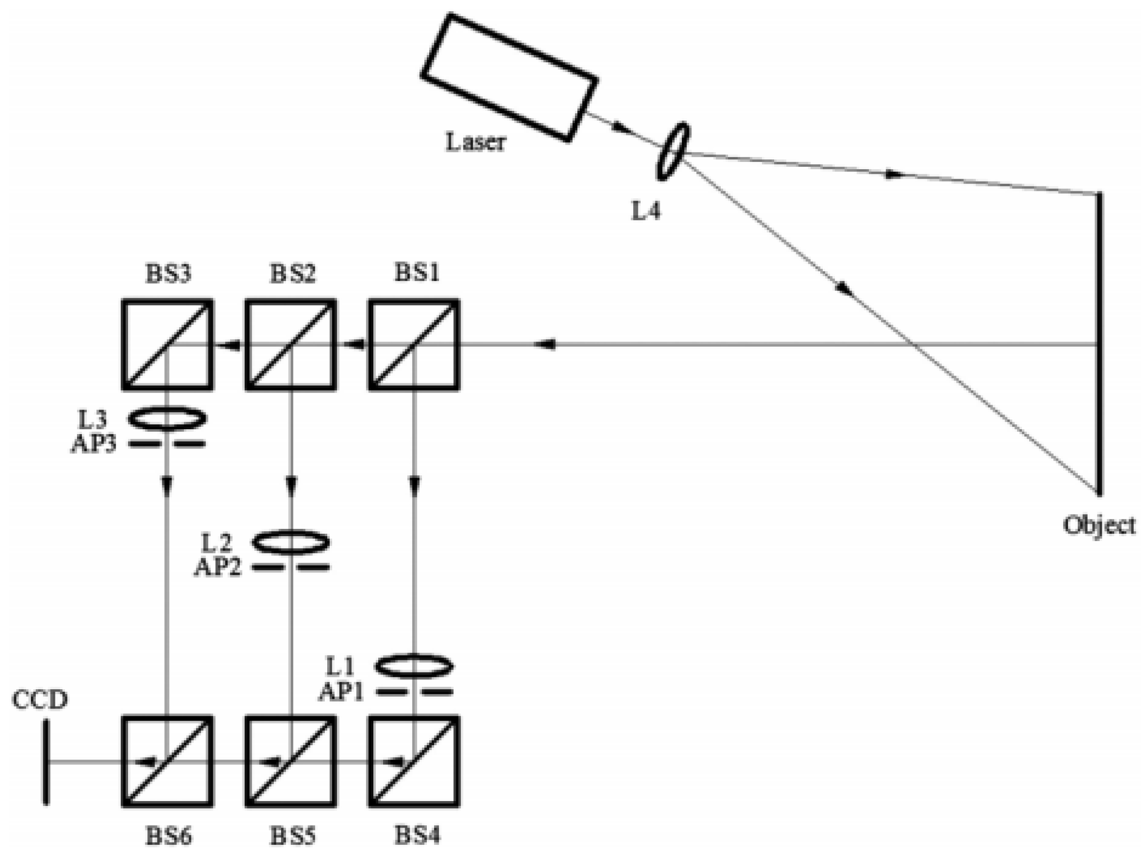
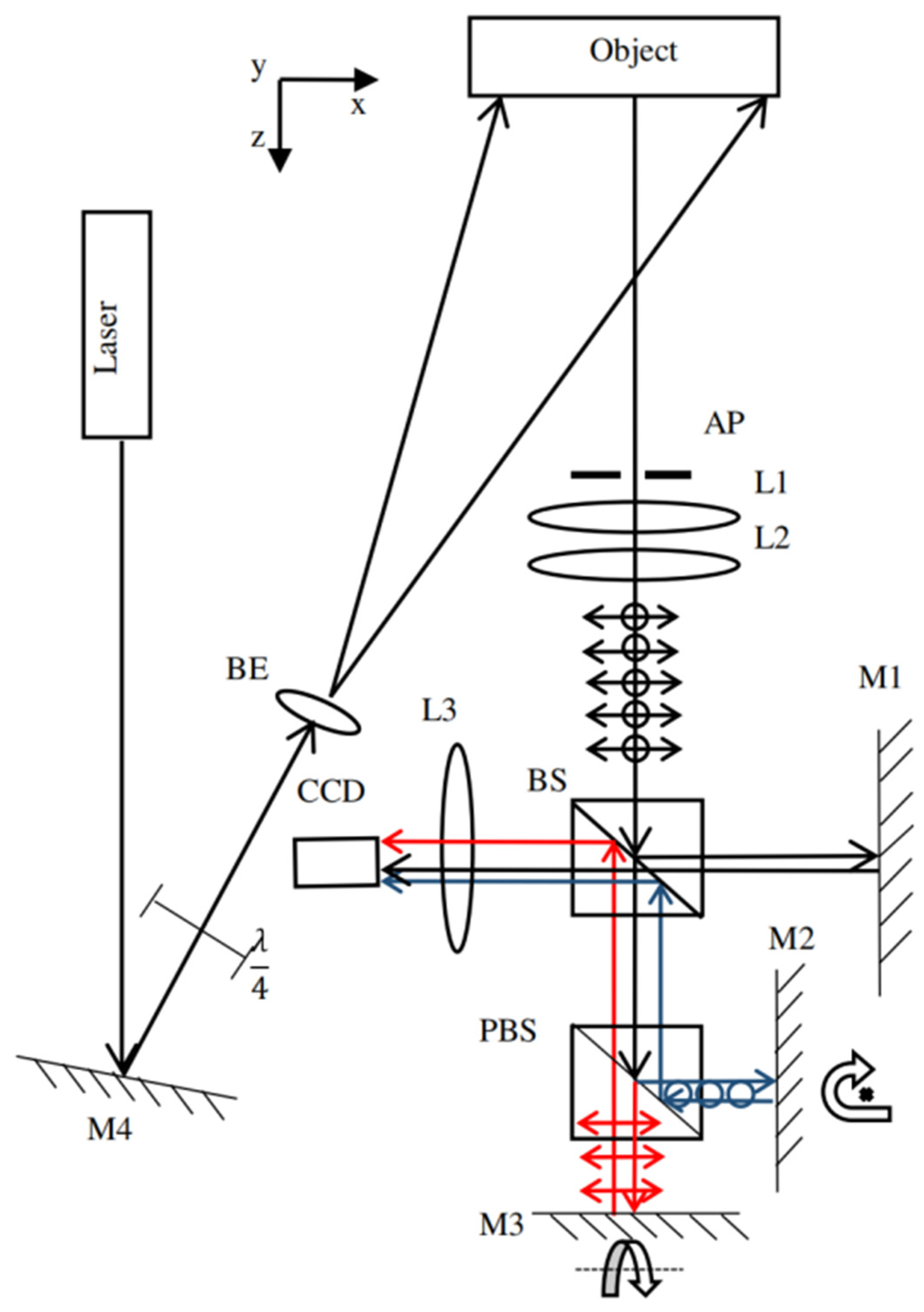
3.2. Dual-Directional Measurement Application in Spatial Phase-Shift (SPS) Technique

Dual-directional SPS shearography is discussed in the following paragraphs, along with the advantages and limitations of the technique. The main techniques used in dual-directional SPS shearography include multi-aperture, multi-wavelength, and polarization systems.

3.2.1. Dual-Directional Spatial Phase-Shift Technique

Due to the properties of the SPS technique, the carrier frequencies allow multiple pieces of information to share one image plane. Information with different carrier frequencies has a separate area on the frequency domain, making this another viable means for dual shearing direction measurement. Generally, two vertical shearing measurements are performed in the dual-directional spatial phase-shift shearography technique. As the quality of the shearography result depends on the shearing direction, the defect or deformation will be more apparent [24]. Although some of these settings perform well, they may also introduce new problems, such as poor phase image quality and low light efficiency. In addition, the dual-directional measurement of the spatial phase shift doubles the test time, which ultimately leads to an increase in test costs. The main problem of this configuration is the complexity of the data generated by the interfering shearing image and the workload of separating each shearing component.
Recently, there have been great developments and advances in dual-directional shearing shearography technology. These developments and advancements are introduced and discussed in subsequent sections.

3.2.2. Recent Developments in Dual-Directional SPS Technique

SPS-based dual-directional shearography separates the channels based on the use of different methods. One method is to utilize multiple apertures. This method introduces multiple apertures to assist in adjusting the shearing amount and spatial carrier frequency. In 1972, Duffy first described a double-aperture imaging system to introduce a fringe structure in interferograms [25]. In this method, two separated beams can be regarded as emanating from the virtual apertures. After that, the multi-aperture technique was introduced into the SPS technique. On another hand, based on the theory of multiple apertures, the variable distance between the lens and the aperture varies the amount of shearing light and the spatial carrier during the process [26].
Based on this concept, Barrera et al. introduced an aperture-based spatial phase-shift digital shearography system, shown in Figure 12, and the Fourier domain, shown in Figure 13 [27]. Each aperture attached a wedge prism to produce a shearing amount for separating the spectrums on the Fourier domain. The beams pass through apertures 1 and 2, producing vertical shearing spectrums, and the horizontal spectrums can be found by the interfered beams passing through apertures 2 and 3. The position of each aperture and wedge prisms are fixed during one experimental test, which makes the optical path structure more stable than that in other methods. Then, due to the stable structure, this system offers decent phase-map quality. In this system, applying a single-wavelength laser will not change the light property. However, the measurement size is still limited due to the wedge prism. Thus, the distance between the apertures needs to be adjusted and designed for the object being measured. Additionally, it is challenging to adjust the shearing amount and carrier frequency when using the wedge prism. Due to the multi-aperture method applied, the two orthogonal direction channels will interfere and produce an extra channel. Though this setup can realize the dual-directional measurement, the additional channel will bring high energy leakage to the system. The additional channel also occupies space on the Fourier spectrum, reducing the amount of relevant information that can be captured.
To solve the problem of adjusting spatial frequency and shearing amount, Wang developed a system, shown in Figure 14, based on the theory of common optical path design [25]. The beam splitter divides the laser light into a new channel that replaces one aperture in a three-aperture system to record one-dimensional information. Spatial frequency results from the introduction of the mirror and beam splitters into the system, and the shearing amount can be adjusted freely. The channels are divided by the apertures and the Wollaston prism. The Wollaston prism also distinguishes the channels and produces the shearing amount. However, the beam splitter and mirror enrollment increase the energy leakage and reduce system stability. The Wollaston prism also limits the field of view size.
Zhong integrated a double Mach–Zehnder interferometer system into the multi-aperture technique to measure dual-directional strain data [28]. Compared with the previous methods, this method reduces a laser and uses another Mach–Zehnder interferometer to separate a new channel and create the other shearing direction. In this method, the scattered light from the surface of the object is split into three beams by two beam splitters in order. One of the beams will not be sheared but considered as the reference beam. The mirrors in optical paths introduce the shearing amount in dual directions. Additionally, the aperture set on each channel is to separate the spatial carrier frequency. Then, the reference beam combined the two sheared beams with another two beam splitters, which can be considered a multiplexed Mach–Zehnder interference system. Three images formed by the interfering effect on a CCD camera are shown here. The relative shearing amount can be changed for the three images by adjusting mirrors M1, M2, and M3. Furthermore, the carrier frequency is introduced by the misalignment of aperture stops. The system allows for more flexibility in adjusting the shearing amount and carrier frequency, but the extra Mach–Zehnder interferometer used in the system increases the optical structure complexity and energy leakage. In 2021, Yan modified Zhong’s system with another beam splitter and an aperture, as shown in Figure 15 [29]. The new optical components bring a new channel into the system, allowing the setup to measure three directional information. However, it is not easy to adjust the shearing amount using beam splitters, and the adjustment will also cause a certain degree of shift of the optical axis.
Compared with multi-aperture methods, another method is the one introduced by Wang, using a multi-wavelength laser in the dual-directional SPS system, as shown in Figure 16 [16]. This system was the first to perform simultaneous dual-directional shearography measurements using a single CCD camera under dynamic loading. This system is based on the use of the Michelson interferometer to simultaneously measure two shearograms in two orthogonal shearing directions by two-wavelength lasers. Two optical band-pass filters are enrolled into the system to avoid cross-interference. As can be seen from Figure 16, beam splitter 1 splits the beam into two channels. Filters 1 and 2 allow one beam to measure directional information and record it on a CCD camera. Data on the different directions can be obtained from WIFT on the Fourier spectrum. However, data quality compensation is required due to the different wavelengths of the lasers.
Xie applied a polarization system to the dual-direction SPS technique to improve the two-laser system and avoid cross-interference. The schematic of this system is shown in Figure 17 [30]. The polarizer separates the beam into directions. Figure 18 shows that, after polarization, each directional beam measures one-directional information. The two beams are divided by the two Mach–Zehnder interferometers, followed by interference at the CCD camera. Compared with the multi-wavelength method, in this method, the two shearograms are separated by a polarization design during the experiment. Then, the carrier frequencies are used to generate phase map Shearograms. Compared with the multi-aperture method, this system uses polarization instead of apertures to switch shearing directions, with no moving parts to improve light efficiency. The polarization system and polarized beam splitter separate the channel, and the introduction of two Mach–Zehnder interferometers makes the shearing amount adjustable. The multiple beam splitters can independently adjust the relationship between the reference angle and the shearing amount. However, the complicated optical structure brings low robustness and serious energy leakage. In addition, the energy leakage cannot be avoided due to the coating film on the polarizing device and polarized beam splitter.
To increase the robustness and reduce energy leakage, Zhang improved the optical structure by using the Michelson interferometer instead of the Mach–Zehnder interferometer. This system’s schematic is shown in Figure 18 [31]. System robustness increased due to the more straightforward setup, while the cost and energy leakage decreased. However, compared with the Mach–Zehnder interferometer, the Michelson interferometer results in less flexibility in adjusting the relationship between the reference angle and shearing amount due to limitations in the tilting angles of the reflection mirror and shearing.

4. Potentials and Limitations

4.1. Potentials

Along with maintaining the benefits of basic shearography, dual-directional measurement shearography has many advantages that exhibit its unique superiority, some of which include the following features:
  • In the basic shearography system, a single shearing-direction shearography system may fail to detect the defect if the wrong shearing direction is selected. The dual-directional measurement shearography technique solves the problem by quantifying the first derivative of two different directions of deformation simultaneously.
  • Two different directional measurements need to be carried out, twice successively with orthogonal shearing directions. However, in practice, the measurement conditions and the loading events are not reproducible. In the dual-directional measurement shearography technique, different directional measurements are executed simultaneously. Therefore, it enhances the precision compared to the basic shearography system.
  • The process of simultaneous measurement will reduce cost and calibration effort and lower susceptibility.
  • The technique has broad development prospects, as it can also be developed for three-dimensional, radial, and lateral measurements.

4.2. Limitations

Although some limitations have been resolved, there are still problems that need to be solved, which include the following issues:
  • The dual-directional measurement technique applied in the TPS system can only measure static conditions. However, the phase-map quality for the dual-directional SPS technique is still not as good as that for dual-directional TPS.
  • As the dual-directional measurement will require multiple optical components, the cost of the system cannot be ignored.
  • For the dual-directional SPS system, the shearing amount needs to be large enough to separate the spectrums on the Fourier domain to obtain a better quality phase map. However, a larger shearing amount will reduce the size of the area of interest that can be captured and measured with accuracy.
  • The Michelson interferometer application cannot adjust carrier frequency and shearing amount separately, limiting the system sensitivity.
  • The technique improves the sensitivity of shearography. As an interference-based technique with many optical components, the higher sensitivity allows the system to more easily be impacted by environmental disturbances that rise in setup, thus resulting in greater error accumulation.
  • A large amount of energy from the laser is lost due to the number of beam splitters and polarization beam splitters used in dual-directional shearography systems, so high-intensity lasers and system stability are required.
  • For the multi-wavelength dual-directional measurement shearography technique, different wavelength beams create different carrier frequencies, allowing the condition of overlapping spectra to be avoided. However, it may not be possible to eliminate the influence of interference completely.
  • Even though the SLM technique solves most problems, the high cost of devices makes it not suitable for the industry.

5. Conclusions

Multiple dual-directional shearography and their applications for NDT/NDE were reviewed in this paper. Shearography measures the first derivative of deformation and reveals defects in an object by identifying defect-induced anomalies of the first derivative of deformation. The direction of the first derivative of deformation depends on the shearing direction; therefore, inspection results of shearography are sensitive to the shearing direction. To overcome this limitation, different dual-directional/shearing shearographic systems have been developed over the last few decades. They can be classified into two categories, i.e., duel-shearing TPS and SPS shearographic systems. The dual-directional TPS shearography is a sensitive, effective, and accurate technique. It has a high-quality phase map based on multi-equation algorithms and various kinds of optics constructions. It is recommended for application in a shearographic test under a static loading condition. The dual-directional SPS shearography can measure dual-directional information in the dynamic loading conditions based on carrier frequency methods and corresponding optical setups. Both techniques have advantages and limitations but have their practical applications. When higher phase image quality is required, dual-directional TPS shearography is often applied. When working under dynamic loading conditions, dual-directional SPS shearography is a better choice. This paper introduced the various developments under these two broad technical concepts. The future direction of development includes aspects such as simplified structure, high laser efficiency, good phase-map quality, real-time measurement, and low cost. As an advanced NDT technique, dual-directional shearography is not just an academic concept but is expected to be deployed in the industry. It offers a broader range of quantitative and qualitative measurements of deformities, which can widen its application, especially in the field of NDE and NDE.

Author Contributions

Conceptualization, B.G. and Y.F.; methodology, B.G. and L.Y.; validation, X.Z., B.Z., B.S. and L.Y.; formal analysis, B.G. and B.Z.; investigation, B.G.; resources, S.F. and L.Y.; writing—original draft preparation, B.G.; writing—review and editing, L.Y., B.S. and B.G.; visualization, Y.F., S.F. and B.G.; project administration, B.G., X.Z. and B.Z. All authors have read and agreed to the published version of the manuscript.

Funding

This research received no external funding.

Institutional Review Board Statement

Not applicable.

Informed Consent Statement

Not applicable.

Data Availability Statement

The Figure 1 and Figure 2 presented in this study are openly available in [Applied science at [https://doi.org/10.3390/app8122662], reference number [10]. Restrictions apply to the availability of these data. Figure 3 was obtained from [SPIE] and are available [from the Dr. Lianxiang Yang] with the permission of [SPIE]. Restrictions apply to the availability of these data. Figure 4 was obtained from [Applied Optics] and are available [from the Dr. Boyang Zhang/ https://doi.org/10.1364/AO.404088] with the permission of [Applied Optics]. Restrictions apply to the availability of these data. Figure 5 was obtained from [SPIE] and are available [from the Dr. Lianxiang Yang] with the permission of [SPIE]. Restrictions apply to the availability of these data. Figure 6 was obtained from [SPIE] and are available [from the Dr. Thorsten Siebert/ https://doi.org/10.1117/12.343778] with the permission of [SPIE]. The Figure 7 presented in this study are openly available in [Optical laser technology at [https://doi.org/10.1016/j.optlastec.2015.04.015], reference number [20]. The Figure 8 presented in this study are openly available in [Measurement Science and Technology at, reference number [21]. Restrictions apply to the availability of these data. Figure 9 was obtained from [Applied Optics] and are available [from the Dr. Boyang Zhang/ https://doi.org/10.1364/AO.404088] with the permission of [Applied Optics]. The Figure 10 presented in this study are openly available in [Optical laser technology at [https://doi.org/10.1016/j.optlaseng.2015.08.007], reference number [22]. The Figure 11 presented in this study are openly available in [Applied optics at [https://doi.org/10.1364/AO.394218], reference number [23]. The Figure 12 and Figure 13 presented in this study are openly available in [Optical laser technology at [https://doi.org/10.1016/j.optlaseng.2018.07.018], reference number [27]. Restrictions apply to the availability of these data. Figure 14 was obtained from [Applied Optics] and are available [from the https://doi.org/10.1364/AO.58.000593] with the per-mission of [Applied Optics]. Restrictions apply to the availability of these data. Figure 15 was obtained from [SPIE] and are available [from the Dr. Yonghong Wang/ https://doi.org/10.1117/1.OE.58.5.054105] with the permission of [SPIE]. The Figure 16 presented in this study are openly available in [Optical laser technology at [https://doi.org/10.1016/j.optlaseng.2015.12.009], reference number [16]. The Figure 17 presented in this study are openly available in [Review of Scientific Instruments at [https://doi.org/10.1063/1.4961473reference number [30]. Restrictions apply to the availability of these data. Figure 18 was obtained from [Experimental Techniques] and are available [from the Dr. Boyang Zhang/ https://doi.org/10.1007/s40799-019-00345-9] with the permission of [Experimental Techniques].

Acknowledgments

The authors would like to express their sincere thanks to Bernard Sia, who made careful corrections to the manuscript and improved the English.

Conflicts of Interest

The authors declare no conflict of interest.

References

  1. Wang, B.; Zhong, S.; Lee, T.L.; Fancey, K.S.; Mi, J. Non-destructive testing and evaluation of composite materials/structures: A state-of-the-art review. Adv. Mech. Eng. 2020, 12. [Google Scholar] [CrossRef] [Green Version]
  2. Schnars, U.; Jüptner, W.P. Digital recording and numerical reconstruction of holograms. Meas. Sci. Technol. 2002, 13, R85. [Google Scholar] [CrossRef]
  3. Yang, L.; Zhang, P.; Liu, S.; Samala, P.R.; Su, M.; Yokota, H. Measurement of strain distributions in mouse femora with 3D-digital speckle pattern interferometry. Opt. Lasers. Eng. 2007, 45, 843–851. [Google Scholar] [CrossRef] [Green Version]
  4. Xu, N.; Xie, X.; Harmon, G.; Gu, R.; Yang, L. Quality inspection of spot welds using digital shearography. SAE Int. J. Mater. 2012, 5, 96–101. [Google Scholar] [CrossRef]
  5. Chen, X.; Yang, L.; Xu, N.; Xie, X.; Sia, B.; Xu, R. Cluster approach based multi-camera digital image correlation: Methodology and its application in large area high temperature measurement. Opt. Laser. Technol. 2014, 57, 318–326. [Google Scholar] [CrossRef]
  6. Petry, M.E.C.; Schuth, M. Spatial phase shift shearography for enhanced NDT. NDT E. Int. 2018.SHM-NDT 2018. Available online: https://www.ndt.net/article/shmndt2018/papers/SHM-NDT-2018_paper_39.pdf (accessed on 4 January 2022).
  7. Hooshmand-Ziafi, H.; Hassani, K.; Dashtdar, M. Dual-sensitive spatial phase-shifting shearography based on a common-path configuration. Opt. Eng. 2019, 58, 114104. [Google Scholar] [CrossRef]
  8. Steinchen, W.; Yang, L.X.; Kupfer, G.A.; Mäckel, P.; Vössing, F. Strain analysis by means of digital shearography: Potential, limitations and demonstration. J. Strain. Anal. Eng. Des. 1998, 33, 171–182. [Google Scholar] [CrossRef]
  9. Shang, H.M.; Hung, Y.Y.; Luo, W.D.; Chen, F. Surface profiling using shearography. Opt. Eng. 2000, 39, 23–31. [Google Scholar] [CrossRef]
  10. Zhao, Q.; Dan, X.; Sun, F.; Wang, Y.; Wu, S.; Yang, L. Digital shearography for NDT: Phase measurement technique and recent developments. Am. J. Appl. Sci. 2018, 8, 2662. [Google Scholar] [CrossRef] [Green Version]
  11. Steinchen, W.; Yang, L.X. Digital Shearography; SPIE Press: Bellingham, DC, USA, 2003. [Google Scholar]
  12. Bhaduri, B.; Mohan, N.K.; Kothiyal, M.P. Simultaneous measurement of out-of-plane displacement and slope using a multiaperture DSPI system and fast Fourier transform. J. Appl. Opt. 2007, 46, 5680–5686. [Google Scholar] [CrossRef] [PubMed]
  13. Burke, J.; Helmers, H. Spatial versus temporal phase shifting in electronic speckle-pattern interferometry: Noise comparison in phase maps. J. Appl. Opt. 2000, 39, 4598–4606. [Google Scholar] [CrossRef] [PubMed]
  14. Pedrini, G.; Osten, W.; Gusev, M.E. High-speed digital holographic interferometry for vibration measurement. J. Appl. Opt. 2006, 45, 3456–3462. [Google Scholar] [CrossRef] [PubMed]
  15. Xie, X. Development of Michelson Interferometer Based Spatial Phase-Shift Digital Shearography. Ph.D. Dissertation, Oakland University, Oakland, MI, USA, 2016. [Google Scholar]
  16. Wang, Y.; Gao, X.; Xie, X.; Wu, S.; Liu, Y.; Yang, L. Simultaneous dual directional strain measurement using spatial phase-shift digital shearography. Opt. Lasers Eng. 2016, 87, 197–203. [Google Scholar] [CrossRef]
  17. Zhang, B.; Sun, F.; Yang, L.; Yang, L. Spatial-light-modulator-based dual shearing direction shearography. J. Appl. Opt. 2020, 59, 11080–11086. [Google Scholar] [CrossRef]
  18. Yang, L.X.; Steinchen, W.; Schuth, M.; Kupfer, G. Precision measurement and nondestructive testing by means of digital phase shifting speckle pattern and speckle pattern shearing interferometry. Measurement 1995, 16, 149–160. [Google Scholar] [CrossRef]
  19. Siebert, T.; Schmitz, B. New shearing setup for simultaneous measurement of two shear directions. Int. J. Opt. Photon. 1999, 3637, 225–230. [Google Scholar]
  20. Bai, P.; Zhu, F.; He, X. Out-of-plane displacement field measurement by shearography. Opt. Laser Technol. 2015, 73, 29–38. [Google Scholar] [CrossRef]
  21. Groves, R.M.; James, S.W.; Tatam, R.P. Polarization-multiplexed and phase-stepped fiber optic shearography using laser wavelength modulation. Meas. Sci. Technol. 2000, 11, 1389. [Google Scholar] [CrossRef]
  22. Richoz, G.L.; Schajer, G.S. Simultaneous two-axis shearographic interferometer using multiple wavelengths and a color camera. Opt. Lasers Eng. 2016, 77, 143–153. [Google Scholar] [CrossRef]
  23. Jiang, H.; Ma, Y.; Dai, M.; Dai, X.; Yang, F.; He, X. Panoramic dual-directional shearography assisted by a bi-mirror. J. Appl. Opt. 2020, 59, 5812–5820. [Google Scholar] [CrossRef] [PubMed]
  24. Burnett, M.; Bryanston-Cross, P.J. Measurements of transonic shock structures using shearography. In Laser interferometry VIII: Applications. Int. J. Opt. Photon. 1996, 2861, 124–135. [Google Scholar]
  25. Wang, S.; Dong, J.; Pöller, F.; Dong, X.; Lu, M.; Bilgeri, L.M.; Koch, A.W. Dual-directional shearography based on a modified common-path configuration using spatial phase shift. J. Appl. Opt. 2019, 58, 593–603. [Google Scholar] [CrossRef] [PubMed]
  26. Duffy, D.E. Moiré gauging of in-plane displacement using double aperture imaging. J. Appl. Opt. 1972, 11, 1778–1781. [Google Scholar] [CrossRef] [PubMed]
  27. Barrera, E.S.; Fantin, A.V.; Willemann, D.P.; Benedet, M.E.; Goncalves, A.A., Jr. Multiple-aperture one-shot shearography for simultaneous measurements in three shearing directions. Opt. Lasers Eng. 2018, 111, 86–92. [Google Scholar] [CrossRef]
  28. Zhong, S.; Sun, F.; Wu, S.; Bao, F.; Wang, Y. Multi-directional shearography based on multiplexed Mach–Zehnder interference system. J. Mod. Opt. 2020, 67, 346–354. [Google Scholar] [CrossRef]
  29. Yan, P.; Sun, F.; Dan, X.; Zhao, Q.; Wang, Y.; Lu, Y. Spatial phase-shift digital shearography for simultaneous measurements in three shearing directions based on adjustable aperture multiplexing. Opt. Eng. 2019, 58, 054105. [Google Scholar] [CrossRef]
  30. Xie, X.; Lee, C.P.; Li, J.; Zhang, B.; Yang, L. Polarized digital shearography for simultaneous dual shearing directions measurements. Rev. Sci. Instrum. 2016, 87, 083110. [Google Scholar] [CrossRef]
  31. Zhang, B.; Xu, W.; Li, J.; Siebert, T.; Yang, L. Modified Michelson interferometer based dual shearing single camera digital sherography. Exp. Tech. 2020, 44, 187–195. [Google Scholar] [CrossRef]
Figure 1. The schematic of digital shearography (open access, from [10] © Applied Sciences MDPI).
Optics 03 00014 g001
Figure 2. Spectrum of recorded speckle pattern image (open access, from [10] © Applied Sciences MDPI).
Optics 03 00014 g002
Figure 3. The measuring results of the different shearing directions in plastic board: (a) shearing in x-direction; (b) shearing in y-direction (reprinted/adapted with permission from [11] © SPIE).
Optics 03 00014 g003
Figure 4. Dual-directional shearing measurement phase map in x- and y-direction shearing of a 5 mm thick plastic board: (a) phase map of x-direction shearing; (b) phase map of y-direction shearing (reprinted/adapted with permission from [17] © The Optical Society).
Optics 03 00014 g004
Figure 5. Schematic of digital shearography for measuring both ∂w/∂x and ∂w/∂y under a single loading (reprinted/adapted with permission from [11] © SPIE).
Optics 03 00014 g005
Figure 6. Schematic of new shearing setup for simultaneous measurement of two shear directions: (reprinted/adapted with permission from [19] © SPIE).
Optics 03 00014 g006
Figure 7. Schematic of Bai’s system: BS, beam splitter; AS, aperture; M, mirror (open access, from [20] © Optical Laser Technology).
Optics 03 00014 g007
Figure 8. Schematic of the experimental layout of the complete two-component shearography system: BS, beam splitter; M, mirror; L, lens; PBS, polarized beam splitter; NPBS, non-polarized beam splitter (open access, from [21] © Measurement science and technology).
Optics 03 00014 g008
Figure 9. Schematic of SLM-based dual shearing-direction shearography: BS, beam splitter; M, mirror; L, lens(reprinted/adapted with permission from [17] © The Optical Society).
Optics 03 00014 g009
Figure 10. Schematic of optical configuration of a two-axis shearographic system (open access, from [22] © Optical Laser Engineering).
Optics 03 00014 g010
Figure 11. Schematic of the panoramic dual-directional shearography (open access, from [23] © The Optical Society).
Optics 03 00014 g011
Figure 12. Schematic of Barrera’s system: (a) aperture’s structure; (b) schematic of multi-aperture in dual-directional SPS: BS, beam splitter; M, mirror; L, lens; W, wedge prism (open access, from [27] © Optical Laser Engineering).
Optics 03 00014 g012
Figure 13. Spectrum on the Fourier domain (open access, from [27] © Optical Laser Engineering).
Optics 03 00014 g013
Figure 14. Common optical path double-aperture system: BS, beam splitter; M, mirror; L, lens; AP, aperture; WP, Wollaston prism; HWP, Wollaston half-prism (reprinted/adapted with permission from [25] © The Optical Society).
Optics 03 00014 g014
Figure 15. Schematic representation of the adjustable aperture multiplexing spatial phase-shift digital shearography system: BS, beam splitter; M, mirror; L, lens; AP, aperture (reprinted/adapted with permission from [29] © Optical engineering SPIE).
Optics 03 00014 g015
Figure 16. Schematic of principle of dual-directional shearing spatial phase-shift digital shearography: BS, beam splitter; M, mirror; L, lens; AP, aperture (open access, from [16] © Optical Laser Engineering).
Optics 03 00014 g016
Figure 17. Schematic of the polarized dual-directional shearing spatial phase-shift: BS, beam splitter; M, mirror; L, lens; AP, aperture (open access, from [27] © Review of Scientific Instruments).
Optics 03 00014 g017
Figure 18. The schematic of polarized digital shearography for simultaneous dual-directional shearing measurement with Michelson interferometer: BS, beam splitter; M, mirror; L, lens; AP, aperture; PBS, polarized beam splitter (reprinted/adapted with permission from [29] © SPRINGER NATURE).
Optics 03 00014 g018
Publisher’s Note: MDPI stays neutral with regard to jurisdictional claims in published maps and institutional affiliations.

