Article

Residual Stress in Surface-Grown Cylindrical Vessels via Out-of-Plane Material Configuration

Polytechnic Department of Engineering and Architecture, University of Udine, 33100 Udine, Italy
Appl. Mech. 2025, 6(4), 75; https://doi.org/10.3390/applmech6040075
Submission received: 17 August 2025 / Revised: 3 October 2025 / Accepted: 7 October 2025 / Published: 10 October 2025

Abstract

We consider an axysimmetric cylindrical vessel grown by surface deposition at the inner boundary. The residual stress in the vessel can vary, e.g., depending on the loading history during growth. Can we represent and characterize a stress-free material (namely, reference) configuration for the vessel? Extending an idea initially proposed for surface growth occurring on a fixed boundary, the material configuration is introduced as a two-dimensional manifold immersed in a three-dimensional space. The problem is first formulated in fairly general terms for an incompressible neo-Hookean material in plane strain and then specialized to material configurations represented by ruled surfaces. An illustrative example using geometric and material parameters of carotid arteries shows the characterization of different material configurations based on their three-dimensional slope and computes the corresponding residual stress fields. Finally, such a slope is shown to be in a one to one relationship with the customary measure of residual stress in arteries, i.e., the opening angle in response to a cut. The present work introduces a novel framework for residual stress and shows its applicability in a special setting. Several generalizations and extensions are certainly necessary in the following sections to further test and assess the proposed method.

1. Introduction

Growth and residual stress are almost inextricably connected. Bulk growth can be modeled as an additional inelastic strain, just like thermal and plastic contributions. Whenever a kinematic incompatibility occurs, i.e., the body cannot adapt to the applied inelastic strain without stretching, stress ensues. A very common example is that of two strips of equal length but different materials and temperature bound together. Once thermal equilibrium is reached, the binding prevents the strips from reaching their stress-free configurations. As a result, a stressed, bent configuration is attained in which the two strips are able to partly relieve their stress-free length mismatch.
Modeling of surface growth is generally less straightforward because of the need to account for the addition and subtraction of material points resulting in the evolution of the material configuration (also called “reference” configuration) of the body. Of course residual stress is easily realized in this case too if sequentially added layers have different stress-free lengths, just like in the case of the two strips bound together.
Growth and residual stress are research areas with vast literature and relevance, both in biomechanical and in industrial, technological applications. For residual stresses, two recent review papers can represent a starting point: one by Schajer et al. [1] focusing on measurement methods, and one which is more general by Tabatabaeian et al. [2]. An alternative approach with respect to the present work can be found in the works of Ciarletta et al. [3,4] in which a residually stressed configuration is taken as reference, i.e., without the need for a stress-free material configuration, and the constitutive law depends on the residual stress. For growth, albeit specifically biological, a rather complete reference is the 2017 monography by Goriely [5].
Authors Erlich and Zurlo in a recent work [6], and in earlier ones (e.g., [7]), address the connection between kinematic incompatibility, growth and residual stress in finite strain elasticity and in specific biomechanical applications. A finite strain extension of the bimaterial strip to gels, with modeling choices analogous to the present model can be found in [8]. For the case of cylindrical vessels and arteries in particular, reference is made here to a 2010 work by Holzapfel and Ogden [9] for two reasons. First, it shows the cut method customarily adopted to measure residual stress and obtain a discontinuous (due to the cut) stress-free configuration. Second, it illustrates a two-stage modeling involving two configurations instead of just one material configuration: a stress-free one with the cut, and an unloaded, residually stressed one with restored displacement continuity.
As for surface growth, the present approach relies mainly on the works by Tomassetti and Abeyaratne [10,11,12,13] which build and constantly update a stress-free material configuration of the body. Ideas first introduced in [10] are mainly used here and discussed in more detail below. Works [11,12,13] instead mainly concern stability of surface growth, which is seen as a system of mechanical equations and of a thermodynamically consistent kinetic law. It is worth mentioning that there are several approaches to surface growth. Without claiming completeness, we cite here Yavari and co-authors [14,15] who use a systematic differential geometry approach, and Naghibzadeh et al. [16,17] who propose an Eulerian approach which circumvents the need for a stress-free material configuration altogether.
As mentioned above, the main idea of this work was first proposed, to the author’s knowledge, in Ref. [10]: it consists of managing to construct a stress-free configuration of a surface-grown body as a manifold in a higher dimensional space. For instance, in the case of a body with a two-dimensional spatial configuration (also called “current” configuration), the material configuration can be a surface in a three-dimensional space. In [10] growth occurs on a rigid spherical surface. Here, to make things simpler we briefly illustrate the idea with reference to an annulus growing on the boundary of a rigid disk. Each time a new layer grows stress-free on the disk boundary, the layer previously lying there is pushed outwards and put under tension. Therefore as growth progresses, the radius of each circular layer grows, and so does the tensile stress to which it is subjected. In the material configuration, however, all circular layers have the same stress-free radius, coincident with that of the disk. Hence the proposal of a material configuration represented by a two-dimensional cylindrical surface immersed in a three-dimensional space whose axial coordinate maps into the radius of the annulus in the spatial configuration. Each circle of the cylindrical material configuration has the same radius and maps into a circle of varying radius in the annular spatial configuration.
The purpose of this work is twofold. First, to construct a stress-free material configuration for the annular cross section of a cylindrical vessel with surface growth occurring at the interior boundary, thus extending the work of Tomassetti et al. [10] from a fixed boundary to a free boundary of varying dimension. Second, taking the material configuration as a given, independently of the growth or fabrication process that led to it, to show how it is possible to use it to characterize and model residually stressed configurations of cylindrical vessels such as arteries using just one map from the material to the spatial configuration instead of the two-stage process used, e.g., in Ref. [9].
The present approach is, to the author’s knowledge, novel and it is hoped to be of interest. Several assumptions have been made, axial symmetry and plane strain among them, allowing a significant simplification of the calculations. A finite strain, incompressible neo-Hookean constitutive law, has been adopted. In addition, the kinetics of growth have been neglected here. All of the above choices and limitations could be addressed in future works to extend and assess the method in a more general setting. In particular, a three-dimensional formulation with an axial stretch different from a one-dimensional one would be more appropriate for arteries than the assumption of plane strain.
Another interesting standpoint, though not further pursued here, is to frame the present approach as an instance of an inverse problem. This allows us to benefit from a broad range of existing methods and applications. A starting point to explore this field of research can be represented by Ref. [18].
The content of the paper is organized as follows. Section 2 introduces the material configuration and its map to the spatial configuration. A convenient choice of coordinates emerges quite naturally. Section 3 establishes the relations for the calculation of the Cauchy stress, assuming an incompressible neo-Hookean constitutive behavior. The introduced framework is used in Section 4 to determine a set of material configurations mapping to geometrically identical spatial configurations but having different residual stresses. The general problem is formulated in Section 4.1. Then, in Section 4.2 the search is restricted to a subset of material configurations consisting of ruled surfaces, an assumption suitable in the case of thin vessels. Results are presented using material and geometric parameters chosen from studies on carotid arteries (details on the selection of the parameters are provided in Appendix A). In Section 4.3 radial and circumferential residual stress plots are obtained. Finally, Section 4.4 contains a possibly interesting link between the opening angle of a cut artery customarily used to asses residual stress and a geometric parameter of the material configuration, namely the slope of the ruled surface of revolution.

2. Kinematics

2.1. Spatial and Material Configurations
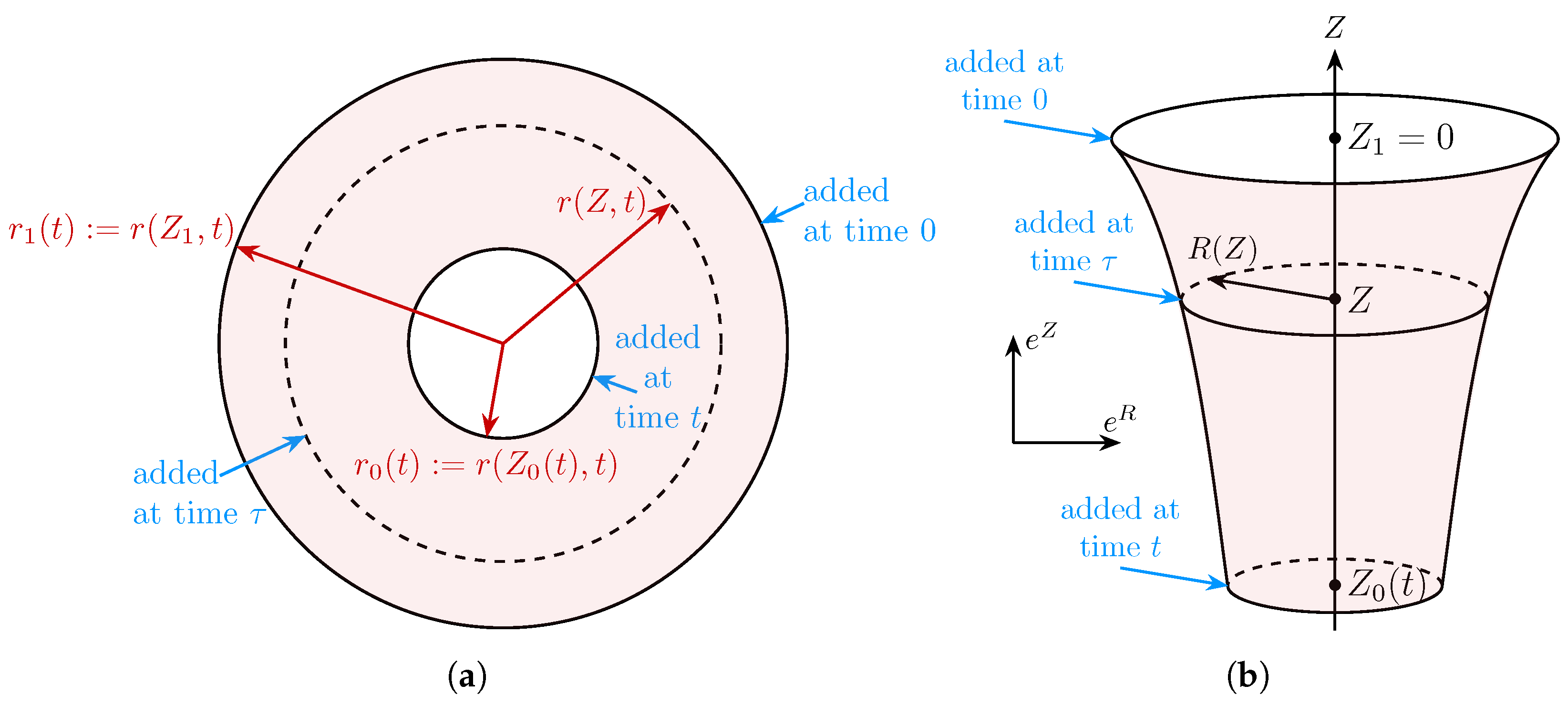
We are concerned throughout with plane strain. In the spatial configuration at time t depicted in Figure 1a, the body is identified with the circular annular region:
R t = { ( r , θ ) : r 0 ( t ) r r 1 ( t ) , 0 θ 2 π , t 0 }
and a generic particle in the body is located at
x = r e r ( θ ) .
Here { e r , e θ } are the orthonormal basis vectors associated with the polar coordinates r , θ :
e r = cos θ e 1 + sin θ e 2 , e θ = sin θ e 1 + cos θ e 2 .
The growth of the body and the applied loading are both axisymmetric, and the material is isotropic in its material configuration. Thus we shall be concerned throughout with axisymmetric configurations only.
In the problem of interest, surface growth occurs at the inner boundary but not the outer boundary. Therefore the inner radius r = r 0 ( t ) is time-dependent due to both deformation and surface growth, whereas the outer radius r = r 1 ( t ) is time-dependent only because of the deformation resulting from the applied loading.
Figure 1. Spatial (a) and material (b) configurations. Can take Z 1 = 0 with no loss of generality. The light red surface in the material configuration maps to the red light surface in the spatial one.
Applmech 06 00075 g001
As shown already in a previous work by Tomassetti et al. (2016) [10], it is possible to generally satisfy kinematic compatibility requirements by embedding the two-dimensional material configuration as an axisymmetric manifold in a three-dimensional space:
R R ( t ) = { ( R , Θ , Z ) : R = R ( Z ) , 0 Θ 2 π , Z 0 ( t ) Z Z 1 } ,
in which a cylindrical coordinate system ( R , Θ , Z ) is adopted. The basis vectors associated with ( R , Θ , Z ) are
e R = cos Θ e 1 + sin Θ e 2 , e Θ = sin Θ e 1 + cos Θ e 2 , e Z = e 3 ,
and a generic point in R R is located at
X = R ( Z ) e R + Z e Z .
The cross section of R R ( t ) at any fixed Z Z 0 ( t ) , Z 1 is a circle of radius R ( Z ) of points all added, i.e., accreted onto the solid, at the same time. Each circle of radius R ( Z ) in the material configuration in Figure 1b maps to a corresponding circle of radius r ( Z , t ) in the spatial configuration in Figure 1a.
Given that growth occurs at the inner boundary, points at Z = Z 1 mapping the circle of radius R ( Z 1 ) to the outer boundary r = r 1 ( t ) were added first, while points at Z = Z 0 ( t ) mapping the circle of radius R ( Z 0 ( t ) ) to the inner boundary r = r 0 ( t ) were added last. Note that the boundary Z = Z 1 in the material configuration is time-independent, reflecting the fact that no growth occurs there. On the other hand the boundary Z = Z 0 ( t ) in the material configuration is time-dependent because growth does occur there. Without loss of generality we set Z 1 = 0 . In the following, let
R 0 ( t ) = R ( Z 0 ( t ) ) and R 1 = R ( Z 1 ) = R ( 0 ) .

2.2. Deformation Gradient

We assume that the deformation that takes X R R x R t is described by
r = r ( Z , t ) , θ = Θ .
Necessarily,
r 0 ( t ) = r ( Z 0 ( t ) , t ) , r 1 ( t ) = r ( Z 1 , t ) .
We now determine the deformation gradient tensor. It follows from (5) and (6) that
d X = R ( Z ) d Z e R + R ( Z ) d Θ e Θ + d Z e Z
where the prime denotes differentiation with respect to Z. Likewise from (2) and (3)
d x = r ( Z , t ) d Z e r + r ( Z , t ) d θ e θ
From (10), we can introduce unit vector
e S = R ( Z ) 1 + ( R ( Z ) ) 2 e R + 1 1 + ( R ( Z ) ) 2 e Z = cos ϕ e R + sin ϕ e Z ,
and rewrite (10) as
d X = R ( Z ) d Θ e Θ + 1 + ( R ( Z ) ) 2 d Z e S
Using (8) and (13) it is possible to express d Z and d θ in (11) in terms of d X as
d x = r ( Z , t ) e r d X · e S 1 + ( R ( Z ) ) 2 + r ( Z , t ) e θ d X · e Θ R ( Z )
from which the deformation gradient F is readily obtainable
d x = r ( Z , t ) 1 + ( R ( Z ) ) 2 e r e S + r ( Z , t ) R ( Z ) e θ e Θ F d X

2.3. A Convenient Change in Variables in the Material Configuration

It is convenient to introduce the orthogonal curvilinear surface coordinates ( Θ , S ) on R R where S is the arc length along a meridional curve R = R ( Z ) , Z 0 ( t ) Z Z 1 = 0 , ( Θ = constant ) . The coordinates Z and S are related by
S = Z Z 1 R ( z ) 2 + 1 d z and S ( Z ) = 1 + ( R ( Z ) ) 2 .
Coordinate S spans from S 0 ( t ) < 0 to S 1 = 0 . With no loss of generality, S 1 is set equal to 0. With this choice, increasing values of S and Z correspond to increasing values of r in R t .
The orthonormal unit vectors { e Θ , e S } are associated with the orthogonal curvilinear coordinates ( Θ , S ) . We introduce functions r ( S , t ) and R ( S ) . Using the chain rule and (16), the relation
r ( S , t ) = r ( Z , t ) 1 + ( R ( Z ) ) 2
is obtained. The prime is used to indicate differentiation with respect to S as well as Z. Using coordinate S and (17) in (15), the expression for the deformation gradient is simplified and becomes
F = λ r ( S , t ) e r e S + λ θ ( S , t ) e θ e Θ
with
λ r ( S , t ) = r ( S , t ) , and λ θ ( S , t ) = r ( S , t ) R ( S )

2.4. Incompressibility

Assuming an incompressible material leads to
λ r ( S , t ) λ θ ( S , t ) = r ( S , t ) r ( S , t ) R ( S ) = 1 ( r 2 ( S , t ) ) = 2 R ( S ) ,
or, using (9) and integrating between S < 0 and S 1 = 0 ,
r 2 ( S , t ) = r 1 2 ( t ) 2 S 0 R ( s ) d s
which expresses the fact that the area of the surface between S 1 = 0 and S in R R is equal to the area of the annular region in R t bounded by r 1 ( t ) and r ( S , t ) in the spatial configuration. The two corresponding surfaces are shaded in Figure 2a,b.

3. Equilibrium

We assume a neo-Hookean constitutive material behavior. Using (19) and incompressibility, namely λ r = 1 / λ θ , the components of the diagonal Cauchy stress tensor are as follows:
T r r = G λ r 2 q T r r ( S , t ) = G R 2 ( S ) r 2 ( S , t ) q ( S , t ) ,
T θ θ = G λ θ 2 q T θ θ ( S , t ) = G r 2 ( S , t ) R 2 ( S ) q ( S , t ) ,
where G is the shear modulus and q the reactive pressure. Pressure loadings p 0 and p 1 are assumed known at the inner and outer boundaries of R t , respectively:
T n = p 0 ( t ) n T r r = p 0 ( t ) on r = r 0 ( t )
T n = p 1 ( t ) n T r r = p 1 ( t ) on r = r 1 ( t )
where n is the outward unit normal vector at the two boundaries of R t . The equilibrium equations in polar coordinates read as follows:
T r r r + T r r T θ θ r = 0 ; T θ θ θ = 0
The second equation is trivially satisfied. The first can be expressed in terms of S using (20):
T r r ( S , t ) r ( S , t ) R ( S ) + T r r ( S , t ) T θ θ ( S , t ) r ( S , t ) = 0
By substituting the expressions (22) and (23) for T r r and T θ θ into the equilibrium Equation (27) and using the boundary condition (25) at the outer boundary S = 0 , the expression for q can be obtained by integration:
q ( S , t ) = p 1 ( t ) + G R 1 2 r 1 2 ( t ) G S 0 2 R ( s ) R ( s ) r 2 ( s , t ) R 3 ( s ) r 4 ( s , t ) 1 R ( s ) d s .
Finally substitution of (28) into (22) and (23) yields the explicit expressions of T r r and T θ θ in terms of S and t satisfying equilibrium in the bulk (26) and the boundary condition (25) at the outer boundary:
T r r = G R 2 r 2 p 1 G R 1 2 r 1 2 + G S 0 2 R R r 2 R 3 r 4 1 R d s
T θ θ = G r 2 R 2 p 1 G R 1 2 r 1 2 + G S 0 2 R R r 2 R 3 r 4 1 R d s
As in the above Equations (29) and (30), in the following, the dependence of functions R, r, T r r and T θ θ with respect to variables S and t may be omitted for brevity.

4. Material Configurations and Residual Stress

We now set a time t and use the introduced framework to exemplify how it is possible to determine a set of material configurations mapping to spatial configurations that are geometrically identical but with different residual stresses.

4.1. Material Configurations Mapping to a Given Spatial Configuration

To this end it is convenient to express both unknown functions r ( S , t ) and R ( S ) in terms of a single newly introduced function U ( S ) using Equation (21)
U ( S ) = S 0 R ( s ) d s , s . t . R ( S ) = U ( S ) and r 2 ( S , t ) = r 1 2 ( t ) + 2 U ( S ) .
In this way U ( S ) becomes the only unknown of the problem. In particular the values taken by function U and its derivative at the inner and outer radii of the spatial and material configuration are
2 U ( S 0 ) = r 0 2 ( t ) r 1 2 ( t ) ; U ( 0 ) = 0
U ( S 0 ) = R 0 ; U ( 0 ) = R 1
In (29) and (30) there is only one equilibrium condition left to satisfy and it is possible to express it in terms of function U ( S ) . Using (31) in (29) and enforcing the traction boundary condition (24) at the inner boundary yields
p 1 p 0 G = ( U ( S 0 ) ) 2 r 1 2 + 2 U ( S 0 ) ( U ( 0 ) ) 2 r 1 2 + 2 U ( 0 ) + S 0 0 2 U ( s ) U ( s ) r 1 2 + 2 U ( s ) ( U ( s ) ) 3 ( r 1 2 + 2 U ( s ) ) 2 1 U ( s ) d s
Given a spatial configuration characterized by radii r 0 and r 1 and boundary pressures p 0 and p 1 , any function U ( S ) satisfying (32) and (34) identifies a material configuration mapping to the assigned spatial configuration and satisfying bulk and boundary equilibrium.

4.2. Ruled Material Surfaces

As an example, let us specifically look at material surfaces that are ruled, i.e., whose meridian curves are straight. This corresponds to assuming a quadratic expression for U ( S )
U ( S ) = a 2 S 2 + b S + c R ( S ) = a S + b
which in turn, means that R is linear in S. Four unknowns need to be determined to define a material configuration: a, b, c and S 0 . Note that a coincides with cos ϕ in Equation (12) and in Figure 2b. Using Equations (32) and (33), it is possible to express the unknowns in terms of R 0 , R 1 , r 0 and r 1 :
a = R 1 2 R 0 2 r 1 2 r 0 2 , b = R 1 , c = 0 , S 0 = r 1 2 r 0 2 R 1 + R 0
Then, using (35) and (36), the equilibrium condition (34) simplifies and becomes
p 1 p 0 G = 1 2 R 0 2 r 0 2 1 2 R 1 2 r 1 2 + R 0 2 R 1 2 r 0 2 r 1 2 ln r 1 r 0 + r 0 2 r 1 2 R 0 2 R 1 2 ln R 0 R 1
Henceforth the computation proceeds numerically using the parameters G = 50.45 kPa, p 0 = 16 kPa, p 1 = 0 kPa, r 1 = 5.4 mm and r 0 = 3.51 mm, whose selection is explained in Appendix A. The parameters are taken from the literature on mechanical modeling of carotid arteries. Arteries are chosen here as an example of cylindrical vessel with residual stress. Though arteries do not presumably form through a surface growth process, we can compare the results with those in the literature and hopefully obtain some useful insight. In addition, Zurlo and Truskinovsky in [19] have obtained a 3D printing protocol for artificial arteries to which the present example may partly relate.
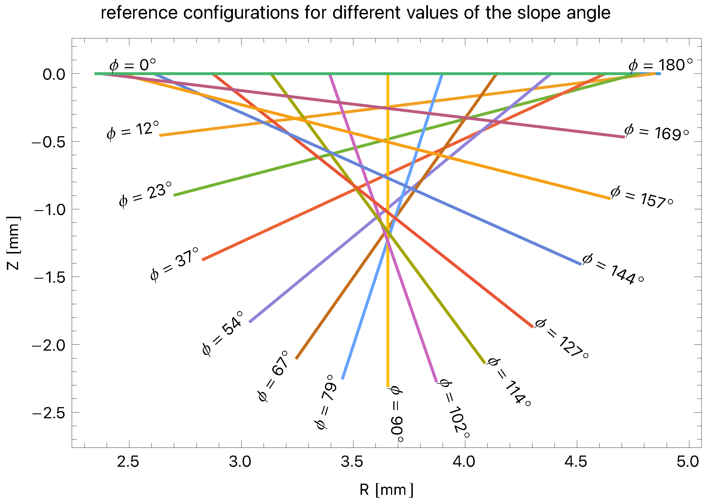
With the spatial configuration being assigned, r 0 and r 1 are known. It is possible to proceed by setting R 1 and seeking a value of R 0 satisfying (37). The solution of nonlinear Equation (37) and subsequent calculations and plots are made with the general purpose computational software Wolfram Mathematica 14.2 [20]. To each choice of R 1 there corresponds a distinct material configuration. Once R 1 and R 0 are known, a, b, c and S 0 are computed from (36). In this way R ( S ) in (35) is determined. Angle ϕ is computed as arccos ( a ) . Admissible solutions, i.e., material configurations mapping to the assigned spatial configuration, are plotted for values of a between 1 and 1, that is, for π ϕ π . They are shown in Figure 3. Values of S 0 , Z 0 = S 0 sin ( ϕ ) , R 0 and R 1 are given in Table 1 for different values of the angle ϕ .
The material configuration corresponding to ϕ = 0 is flat, and has R 0 = 2.62 mm and R 1 = 4.87 mm. The solution corresponding to ϕ = π / 2 is instead cylindrical with R ( S ) = R ( 0 ) = R ( 1 ) = 3.65 mm. Material configurations with a < 0 are characterized by R 0 > R 1 , but det F is still positive and equal to 1. When ϕ = π , R 0 = 2.35 mm and R 1 = 4.7 mm.
The length S 0 of the meridian curves turns out to be almost linear in a = cos ϕ and varies little between ϕ = 0 , where S 0 = 2.25 and ϕ = π , where S 0 = 2.38 .
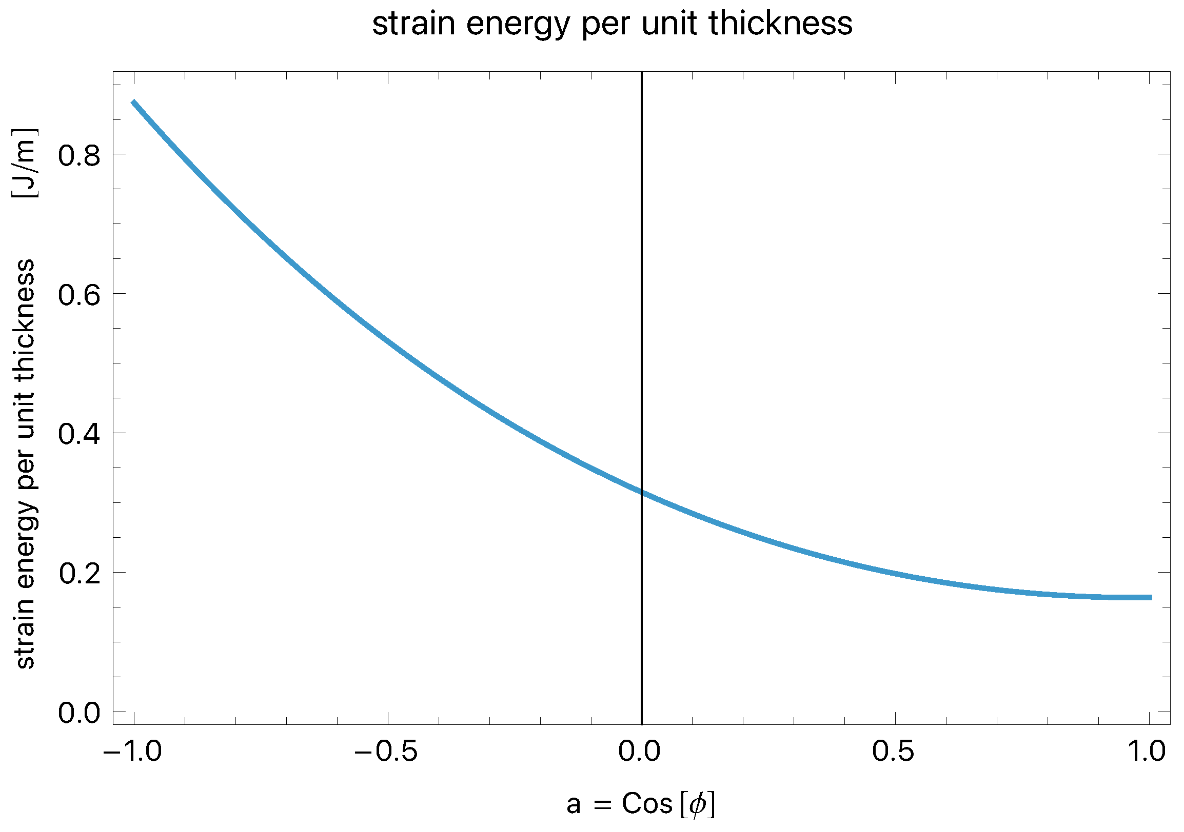
Despite mapping to the same spatial configuration with the same applied loads p 0 = 16 kPa and p 1 = 0 kPa, each truncated cone material configuration whose meridian curve is shown in Figure 3 corresponds to a different value of strain energy per unit thickness measured in J / m .
The energy per unit thickness is computed by integration using formula π G S 0 0 λ r 2 + λ θ 2 2 R ( s ) d s . As shown in Figure 4 the energy is at a minimum for ϕ = 0 and grows monotonically as ϕ goes from 0 to π .

4.3. Residual Stress

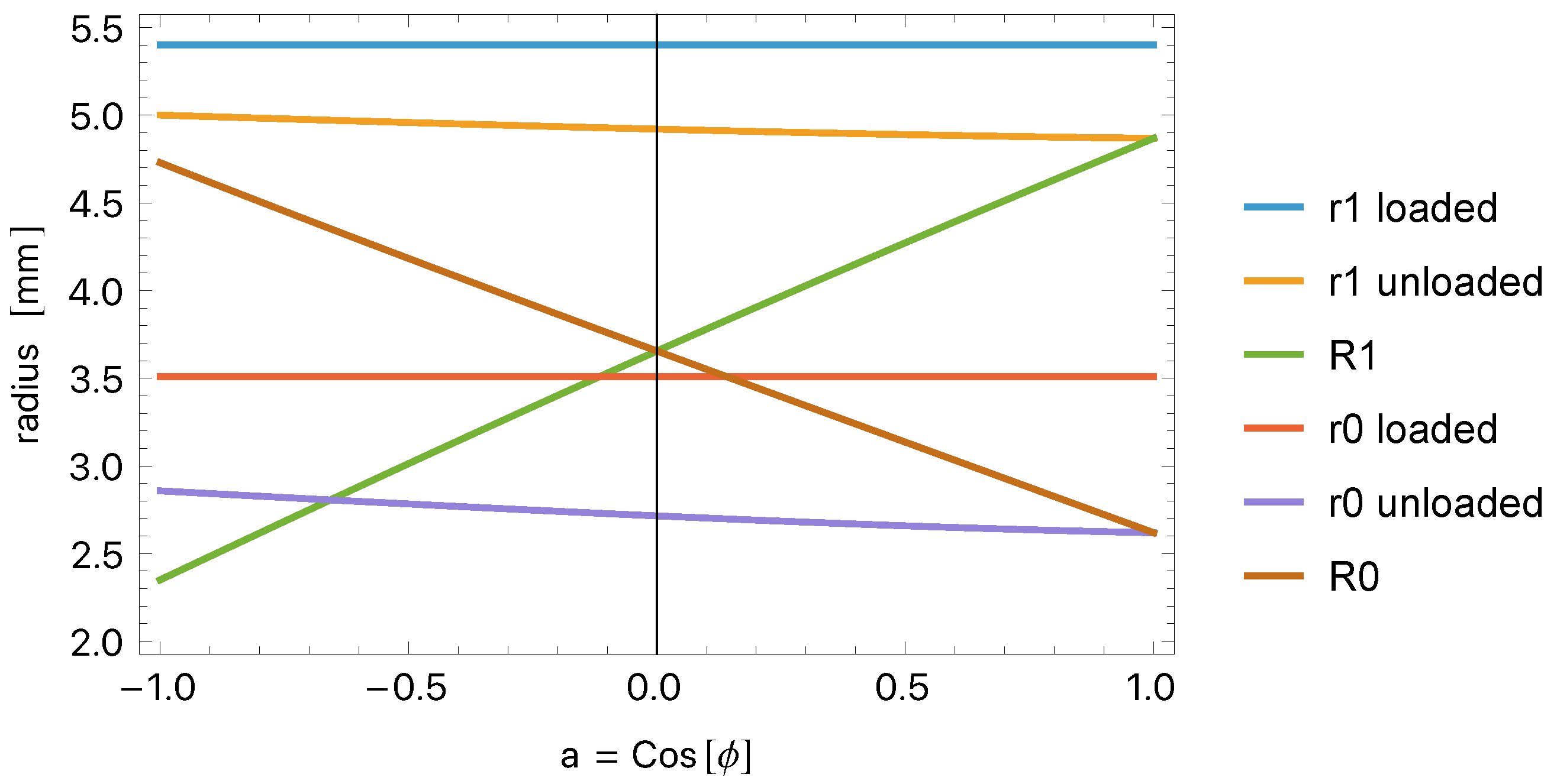
All configurations except ϕ = 0 present residual stress. To put this into evidence, it is possible to compute for each material configuration R ( S ) = a S + b in Figure 3 the unloaded spatial configuration corresponding to p 0 = p 1 = 0 . The unknowns are now r 0 and r 1 , while R 0 and R 1 are known. Function U ( S ) , its parameters a, b, c and the value of S 0 are also known for each material configuration from Equations (36) and (37). Equilibrium condition (37) is used with r 0 expressed in terms of r 1 by means of incompressibility as r 1 2 + 2 U ( S 0 ) , thus leading to a nonlinear equation in the only unknown r 1 . The results are shown in Figure 5. Values of spatial radii r 0 and r 1 in loaded ( p 0 p 1 = 0 ) and unloaded ( p 0 = p 1 = 0 ) conditions and material radii R 0 and R 1 are plotted for different values of a = cos ( ϕ ) ranging from 1 to 1. For a = 1 and a = 1 only, the above values are also displayed in Table 2.
The values of r 0 and r 1 in the loaded configuration are constant because they are equal for all material configurations identified by distinct values of cos ( ϕ ) . Also, as expected, when cos ( ϕ ) = 1 the unloaded values of r 1 and r 0 coincide with the respective material values R 1 and R 0 . They do not coincide for other values of ϕ . The discrepancy increases as cos ( ϕ ) goes from 1 to 1 . It can be noted that R 1 and R 0 are practically linear in cos ( ϕ ) . Looking at (36) and (37), this is not true in general. Therefore it is likely due to the specific values adopted for the parameters and to the fact that in our case S 0 is almost constant regarding ϕ .
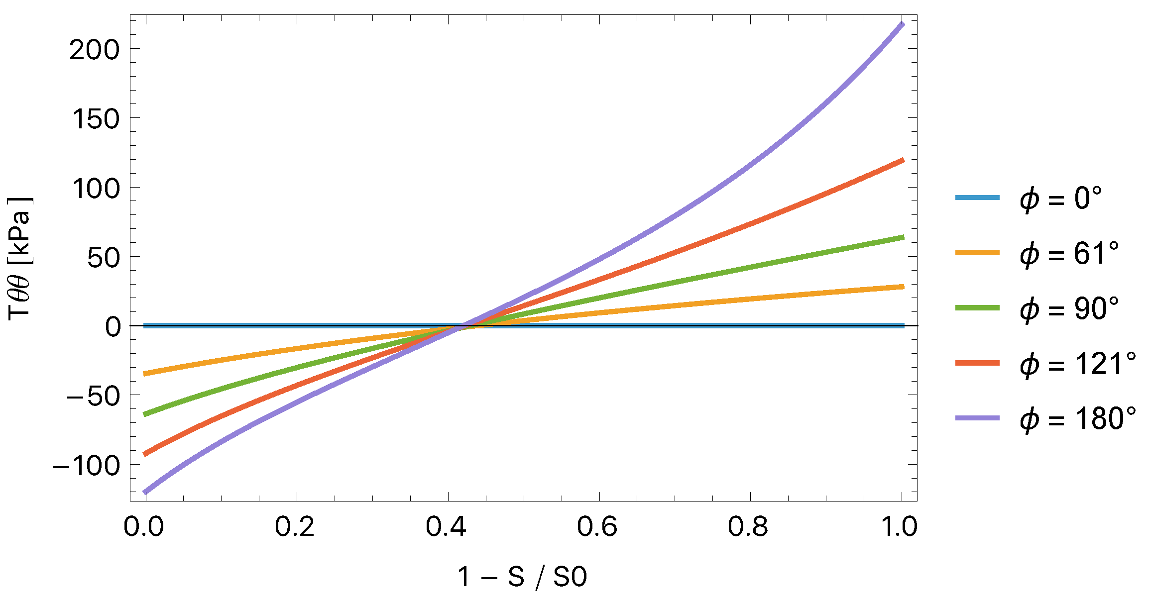
Once the material configuration is defined, R ( S ) is known and r ( S , t ) can be computed from (21). The radial and circumferential residual stresses T r r and T θ θ can then be computed by integration setting p 1 = p 0 = 0 and substituting R ( S ) and r ( S , t ) into Equations (29) and (). Residual stresses T r r and T θ θ are thus computed and are plotted in Figure 6 and Figure 7, respectively, regarding the non-dimensional coordinate ( 1 S / S 0 ) ranging from 0 to 1 for five different values of ϕ , i.e., for five different material configurations.
The stress is zero for ϕ = 0 and it increases monotonically for increasing ϕ , reaching the maximum value for ϕ = π . It is well known that residual stress is present in arteries. This example illustrates how residual stress may arise in a growth process accompanied by applied, possibly non constant, loads.
Among works addressing the evaluation of residual stress in arteries, we mention the works by Holzapfel and Ogden [9], Haghighipour et al. [21] and Altundemir et al. [22]. Overall these works present a more detailed model of the artery with two or three separate layers called intima, media and adventitia, with each layer having different material dimensions. In some cases the axial stretch in the artery is also accounted for. These features should be easily implementable in the present framework. The results in Figure 6 and Figure 7 are in qualitative agreement with the consulted references. Looking a bit more in detail, in all three references [9,21,22] the maximum circumferential residual stress is around 20 kPa and ϕ , deduced from the opening angle via (41) below, is around 30° for [21,22]. Even though a quantitative assessment is beyond the scope of this illustrative example, from Figure 7 it can also be anticipated that in the present case the maximum circumferential stress for ϕ = 30° is expected to be approximately around 20 kPa.

4.4. Opening Angle of the Longitudinally Cut Artery

A common way to assess the amount of residual circumferential stress in an artery consists of taking a cylindrical portion of it and cutting it through the thickness along a meridian curve. Assuming that the cut configuration is completely stress-free, this method allows us to determine the stress-free lengths of material curves such as the outer and inner boundaries of the vessel. Figure 8 exemplifies three possible configurations attainable by a cut artery. The cut vessel adopts the shape of a cylindrical sector. The outer and inner boundaries of the vessel have radius ρ 1 and ρ 0 in the cut configuration, respectively. Each attained configuration is characterized by an angle α between a reference horizontal direction and the outward normal at the cut. It can be seen that α goes from a value smaller than π in the gray configuration in Figure 8 to α = π in the red one and to to α > π in the green one. This means that in the gray configuration, the stress-free length of the outer boundary is larger than that of the inner. In the red configuration, both boundaries have the same stress-free length, while in the green one, the stress-free length of the inner boundary is actually longer than the outer. Because of the annular sector configuration attained, the length of any intermediate radius ρ varies linearly between ρ 0 and ρ 1 .
Interestingly, in the case of ruled material surfaces, radius R also varies linearly between R 0 and R 1 . Hence, once a cylindrical vessel with a ruled material surface is cut, it is completely stress-free and it is possible to establish a direct relation between the ruled surface, i.e., the three-dimensional material configuration in Figure 2b, and the open cylindrical sector in Figure 8. In particular, we can express the angle α in terms of the angle ϕ by which the generatrix of the ruled material surface is inclined with respect to the horizontal direction.
By imposing that the lengths of the inner and outer boundaries coincide in the cut configuration and in the ruled material surface, and by requiring that incompressibility holds, one has the following:
2 π α ρ 0 = 2 π R 0
2 π α ρ 1 = 2 π R 1
π α ρ 1 2 ρ 0 2 = π r 1 2 r 0 2
Equations (38) and (39) can be used to express ρ 0 and ρ 1 in terms of R 0 and R 1 . Then, by substitution of the results into (40), one obtains
π α π = R 1 2 R 0 2 r 1 2 r 0 2 = cos ( ϕ ) = a ,
that is a one to one relationship between angle α and angle ϕ . Note that when α = π , R 1 = R 0 and the material configuration is cylindrical, when instead α > π , and R 0 is larger than R 1 . Equation (41) is useful both as an additional way to associate a tangible parameter, i.e., the angle α , to the three-dimensional material configuration, and vice versa, it is also useful as a way to directly establish the opening angle α once a ruled material surface of slope ϕ is given. In the case of a more general material surface, the angle α corresponds to the local slope of the meridian curve. The ruled surface of constant slope ϕ best approximating the more general material surface could presumably be used to obtain an average estimate for angle α .

5. Conclusions

This work introduced a framework to address plane strain, axisymmetric surface growth in incompressible, cylindrical vessels at finite strains. Growth is assumed to occur only at the interior boundary. A neo-Hookean constitutive behavior is assumed and buckling is neglected. The main idea is drawn from Tomassetti et al. (2016) [10] and consists of constructing a material configuration as a manifold immersed in a space of higher dimension. The formulation of the kinematics and the equilibrium problem appear novel as well, as the method envisaged to determine geometrically identical but differently stressed spatial configurations. In addition, the method seems to lend itself well to the simulation of residually stressed bodies as shown in the illustrative example.
Can this method be useful or could it be simply a peculiar method limited in scope? The hope is certainly that it can provide additional insight into the understanding and modeling of residually stressed bodies at least, initially, for simple geometries. Then a number of incremental extensions can be tackled. A first, interesting benchmark would be to use this approach to replicate the related work by Holzapfel and Ogden [9] since it would encompass three distinct arterial layers with different curvatures at rest and a three-dimensional constitutive model. For future developments, the objective is to generalize and extend aspects of this approach into ideas useful in the computational setting in order to address challenges related to surface growth in several fields.

Funding

This research and the APC were supported by project PRIN 2022 “Stability in statics and dynamics of innovative structural and material systems” funded by the EU through the program NextGenerationEU (PNRR M4.C2.1.1 Code 2022JMSP2J, CUP G53D23001820006).

Institutional Review Board Statement

Not applicable.

Informed Consent Statement

Not applicable.

Data Availability Statement

The original contributions presented in this study are included in the article. Further inquiries can be directed to the corresponding author.

Acknowledgments

The author wishes to thank Rohan Abeyaratne for lengthy and fruitful discussions. The support of the Italian National Group of Mathematical Physics (GNFM-INdAM) is gratefully acknowledged.

Conflicts of Interest

The author declares no conflicts of interest.

Appendix A. Selection of Parameters

Papers by Creane et al. (2010) [23] and by Auricchio et al. (2012) [24] are taken as starting materials for the useful parameter sets they contain. These papers deal with the numerical modeling of carotid arteries with plaque and contain experimental and modeled stress–stretch plots. The value of the neo-Hookean elasticity modulus G = 50.45 kPa is taken from these works. The inner pressure p 0 = 16 kPa = 120 mmHg is taken from Ref. [23]. The outer pressure p 1 is assumed to be 0.
The dimensions of the vessel have been inferred from the work by Tang et al. (2008) [25] which also deals with finite element modeling of carotid artery bifurcations presenting atherosclerotic plaques. Figure 1 in Ref. [25] shows the segmented contour plots of 10 in vivo MRI (Magnetic Resonance Imaging) slices of a carotid artery bifurcation. One of these slices shows 10.8 mm to be the actual outer dimension of the vessel. This datum had been used to set r 1 = 5.4 mm. Image digitization has been used to approximately compute the area of the lumen and estimate the inner radius r 0 = 3.51 mm of a cylindrical vessel of equal area.
Finally, using the equilibrium equation for a neo-Hookean cylindrical vessel in plane strain without residual stress and axial stretch
p 1 p 0 G = ln r 1 R 1 ln r 0 R 0 1 2 R 1 2 r 1 2 R 0 2 r 0 2 ,
and the incompressibility condition R 1 2 R 0 2 = r 1 2 r 0 2 , it is also possible to infer the values of the inner and outer material radii R 0 = 2.62 mm and R 1 = 4.87 mm.

References

  1. Schajer, G.; Prime, M.B.; Withers, P.J. Why Is It So Challenging to Measure Residual Stresses? Exp. Mech. 2022, 62, 1521–1530. [Google Scholar] [CrossRef]
  2. Tabatabaeian, A.; Ghasemi, A.R.; Shokrieh, M.M.; Marzbanrad, B.; Baraheni, M.; Fotouhi, M. Residual Stress in Engineering Materials: A Review. Adv. Eng. Mater. 2022, 24, 2100786. [Google Scholar] [CrossRef]
  3. Ciarletta, P.; Destrade, M.; Gower, A. On residual stresses and homeostasis: An elastic theory of functional adaptation in living matter. Sci. Rep. 2016, 6, 24390. [Google Scholar] [CrossRef]
  4. Gower, A.L.; Shearer, T.; Ciarletta, P.; Destrade, M. The elastic stored energy of initially strained, or stressed, materials: Restrictions and third-order expansions. Proc. R. Soc. A Math. Phys. Eng. Sci. 2025, 481, 20240272. [Google Scholar] [CrossRef]
  5. Goriely, A. The Mathematics and Mechanics of Biological Growth; Springer: New York, USA, 2017. [Google Scholar] [CrossRef]
  6. Erlich, A.; Zurlo, G. Incompatibility-driven growth and size control during development. J. Mech. Phys. Solids 2024, 188, 105660. [Google Scholar] [CrossRef]
  7. Truskinovsky, L.; Zurlo, G. Nonlinear elasticity of incompatible surface growth. Phys. Rev. E 2019, 99, 53001. [Google Scholar] [CrossRef] [PubMed]
  8. Nardinocchi, P.; Puntel, E. Unexpected hardening effects in bilayered gel beams. Meccanica 2017, 52, 3471–3480. [Google Scholar] [CrossRef]
  9. Holzapfel, G.A.; Ogden, R.W. Modelling the layer-specific three-dimensional residual stresses in arteries, with an application to the human aorta. J. R. Soc. Interface 2010, 7, 787–799. [Google Scholar] [CrossRef]
  10. Tomassetti, G.; Cohen, T.; Abeyaratne, R. Steady accretion of an elastic body on a hard spherical surface and the notion of a four-dimensional reference space. J. Mech. Phys. Solids 2016, 96, 333–352. [Google Scholar] [CrossRef]
  11. Abeyaratne, R.; Puntel, E.; Tomassetti, G. Treadmilling stability of a one-dimensional actin growth model. Int. J. Solids Struct. 2020, 198, 87–98. [Google Scholar] [CrossRef]
  12. Abeyaratne, R.; Puntel, E.; Recrosi, F.; Tomassetti, G. Surface accretion of a pre-stretched half-space: Biot’s problem revisited. J. Mech. Phys. Solids 2022, 167, 104958. [Google Scholar] [CrossRef]
  13. Abeyaratne, R.; Puntel, E.; Tomassetti, G. On the Stability of Surface Growth: The Effect of a Compliant Surrounding Medium. J. Elast. 2023, 154, 467–491. [Google Scholar] [CrossRef]
  14. Yavari, A.; Pradhan, S.P. Accretion Mechanics of Nonlinear Elastic Circular Cylindrical Bars Under Finite Torsion. J. Elast. 2022, 152, 29–60. [Google Scholar] [CrossRef]
  15. Pradhan, S.P.; Yavari, A. Accretion-ablation mechanics. Philos. Trans. R. Soc. A Math. Phys. Eng. Sci. 2023, 381, 20220373. [Google Scholar] [CrossRef]
  16. Naghibzadeh, S.K.; Rollett, A.; Walkington, N.; Dayal, K. Accretion and ablation in deformable solids using an Eulerian formulation: A finite deformation numerical method. J. Mech. Phys. Solids 2025, 200, 106076. [Google Scholar] [CrossRef]
  17. Naghibzadeh, S.K.; Walkington, N.; Dayal, K. Surface growth in deformable solids using an Eulerian formulation. J. Mech. Phys. Solids 2021, 154, 104499. [Google Scholar] [CrossRef]
  18. Lesnic, D. Inverse Problems with Applications in Science and Engineering; CRC Press: Boca Raton, FL, USA, 2021; pp. 1–342. [Google Scholar] [CrossRef]
  19. Zurlo, G.; Truskinovsky, L. Printing Non-Euclidean Solids. Phys. Rev. Lett. 2017, 119, 048001. [Google Scholar] [CrossRef]
  20. Wolfram Research, Inc. Mathematica, Version 14.2; Wolfram: Champaign, IL, USA, 2024. Available online: https://www.wolfram.com/mathematica (accessed on 3 October 2025).
  21. Haghighipour, N.; TafazzoliShadpour, M.; Avolio, A. Residual stress distribution in a lamellar model of the arterial wall. J. Med. Eng. Technol. 2010, 34, 422–428. [Google Scholar] [CrossRef]
  22. Altundemir, S.; Lashkarinia, S.S.; Pekkan, K.; Uğuz, A.K. Interstitial flow, pressure and residual stress in the aging carotid artery model in FEBio. Biomech. Model. Mechanobiol. 2023, 23, 179–192. [Google Scholar] [CrossRef]
  23. Creane, A.; Maher, E.; Sultan, S.; Hynes, N.; Kelly, D.J.; Lally, C. Finite element modelling of diseased carotid bifurcations generated from in vivo computerised tomographic angiography. Comput. Biol. Med. 2010, 40, 419–429. [Google Scholar] [CrossRef]
  24. Auricchio, F.; Conti, M.; Ferrara, A.; Morganti, S.; Reali, A. Patient-specific finite element analysis of carotid artery stenting: A focus on vessel modeling. Int. J. Numer. Methods Biomed. Eng. 2012, 29, 645–664. [Google Scholar] [CrossRef]
  25. Tang, D.; Yang, C.; Mondal, S.; Liu, F.; Canton, G.; Hatsukami, T.S.; Yuan, C. A negative correlation between human carotid atherosclerotic plaque progression and plaque wall stress: In vivo MRI-based 2D/3D FSI models. J. Biomech. 2008, 41, 727–736. [Google Scholar] [CrossRef]
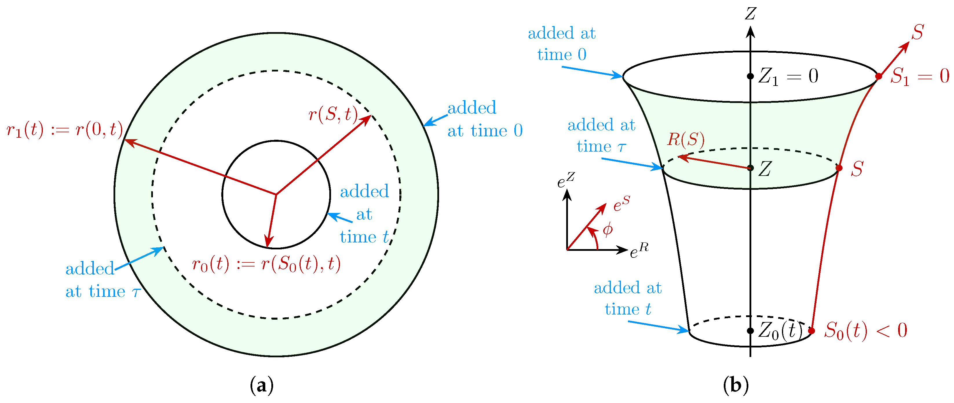
Figure 2. Spatial (a) and material (b) configurations using the arc length S along a meridian curve of the material configuration as coordinate. Shaded surfaces have coincident areas as expressed by Equation (21).
Applmech 06 00075 g002
Figure 3. Straight meridian curves of material configurations all mapping to the same spatial configuration.
Applmech 06 00075 g003
Figure 4. Strain energy per unit thickness of configurations with different angle ϕ .
Applmech 06 00075 g004
Figure 5. Spatial radii r 1 and r 0 of the loaded and unloaded configurations, together with material radii R 1 and R 0 plotted for different material configurations identified by angle ϕ .
Applmech 06 00075 g005
Figure 6. Radial residual stress T r r vs. non-dimensional coordinate 1 S / S 0 for five different material configurations.
Applmech 06 00075 g006
Figure 7. Circumferential residual stress T θ θ vs. non-dimensional coordinate 1 S / S 0 for five different material configurations.
Applmech 06 00075 g007
Figure 8. Angle α characterizing configurations attained by cut artery depending on level of residual stress.
Applmech 06 00075 g008
Table 1. Values of S 0 , Z 0 , R 0 and R 1 for different angles ϕ .
ϕ S 0 Z 0 R 0 R 1
mmmmmmmm
−2.250.0002.624.87
12°−2.25−0.4552.644.84
23°−2.25−0.8962.704.77
37°−2.26−1.3702.834.63
54°−2.27−1.8303.044.38
67°−2.28−2.1003.254.14
79°−2.29−2.2503.453.90
90°−2.30−2.3003.663.66
102°−2.32−2.2703.873.39
114°−2.33−2.1304.083.13
127°−2.34−1.8704.302.87
142°−2.36−1.4004.512.61
157°−2.37−0.9204.642.45
169°−2.38−0.4684.712.38
180°−2.380.0004.732.35
Table 2. Loaded and unloaded radii for a = 1 and a = 1 (all values in mm).
a = 1 a = 1
r 1 loaded5.405.40
r 1 unloaded5.004.87
R 1 2.354.87
r 0 loaded3.513.51
r 0 unloaded2.862.62
R 0 4.732.62
Disclaimer/Publisher’s Note: The statements, opinions and data contained in all publications are solely those of the individual author(s) and contributor(s) and not of MDPI and/or the editor(s). MDPI and/or the editor(s) disclaim responsibility for any injury to people or property resulting from any ideas, methods, instructions or products referred to in the content.