Article

Modeling of Nomex Honeycomb Structure Milling Assisted by Longitudinal–Torsional Vibrations with a CZ10 Combined Tool: Optimization of Tool Wear and Surface Integrity

by
Tarik Zarrouk
1,2,*,
Jamal-Eddine Salhi
3,4,
Mohammed Nouari
2 and
Mohammed Barboucha
1
1
Centre de Recherche (CREHEIO) de L’Ecole des Hautes Etudes d’Ingénierie, Equipe de Production Intégrée, Oujda 60000, Morocco
2
Laboratoire d’Energétique et de Mécanique Théorique et Appliquée, Ecole des Mines de Nancy, Université de Lorraine, F-88100 Saint Dié Des Vosges, France
3
Department of Pure and Applied Mathematics, Saveetha School of Engineering, Saveetha Institute of Medical And Technical Sciences (SIMATS), Chennai 60210, Tamil Nadu, India
4
Laboratory of Energetics (LE), Faculty of Sciences, Abdelmalek Essaadi University, Tetouan 93000, Morocco
*
Author to whom correspondence should be addressed.
Appl. Mech. 2025, 6(3), 47; https://doi.org/10.3390/applmech6030047
Submission received: 29 April 2025 / Revised: 21 June 2025 / Accepted: 28 June 2025 / Published: 30 June 2025

Abstract

Machining Nomex honeycomb cores is essential for manufacturing components that meet the stringent requirements of industrial sectors, but the complexity of this type of structure material requires specialized techniques to minimize defects, ensure optimal surface quality and extend cutting tool life. For this reason, an innovative machining technology based on longitudinal–torsional ultrasonic vibration assistance has been integrated into a CZ10 combined cutting tool, with the aim of optimizing the efficiency of conventional machining processes. To this end, a three-dimensional numerical model based on the finite element method, developed using Abaqus/Explicit 2017 software, was used to simulate the complex interactions between the cutting tool and the thin walls of the structures to be machined. This study aimed to validate the numerical model through experimental tests, quantifying the surface condition, cutting force and tool wear, while evaluating the impact of key machining parameters, such as feed rate and wall thickness, on process performance. The obtained results reveal a substantial reduction in cutting forces, varying from 20 to 40%, as well as a notable improvement in surface finish and a significant extension of tool life. These conclusions open up new perspectives for the optimization of industrial processes, particularly in high-demand sectors such as aeronautics.

1. Introduction

The Nomex honeycomb structure, which forms the core of sandwich structures, is widely used in the aerospace, aeronautics and transportation industries due to its exceptional properties, including specific stiffness, shock resistance, corrosion resistance and vibration absorption [1,2,3,4,5]. Processing Nomex honeycomb structures presents significant difficulties due to their fragile nature and intricate geometry, requiring specialized techniques to handle these materials [6]. It requires specific techniques to preserve structural integrity and ensure optimal results [7]. Ultrasonic machining, a continually evolving method, has been chosen for cutting materials due to its multiple advantages, such as significant reduction in cutting forces, minimal environmental impact and its ability to guarantee optimal precision [8]. Due to the heterogeneous nature of the Nomex honeycomb structure, its machining represents a major technical and scientific challenge. This complexity has led to the need to conduct in-depth experimental research to better understand the specific characteristics of this material [9]. On this subject, Mat Daud et al. [10] investigated the integration of shear thickening fluids (STFs) into sandwich composite structures to enhance their energy absorption capacity under low-speed impact. Their analysis, covering different configurations (without STF, with STF in the core and in the skins), reveals that the addition of STF in the core increases the absorbed energy by 14.51% by optimizing the dissipation of impact energy. In this regard, Duan et al. [11] examined the influence of aluminum honeycomb core architecture on the impact tolerance and residual performance of sandwich structures. Their study shows that parameters such as cell orientation, relative density and core topology significantly affect impact response and residual load capacity. These results highlight the importance of optimized core design to enhance the robustness and safety of sandwich structures under dynamic loading. Furthermore, Xu et al. [12] developed a hybrid friction energy absorption structure, integrating metallic and composite (CFRP) tubes with an innovative clamping system. Through experimentally validated finite element modeling, they demonstrated that the preload applied to the system is essential to increase the absorption force. This approach highlights the potential of hybrid and reusable devices to improve the crash performance of composite structures. Furthermore, it is essential to study the behavior of Nomex honeycomb structures in different machining contexts in order to optimize the processes [13]. These investigations have been addressed in several studies, such as those presented by Jie Xu [14]. This research provides crucial elements for the development of advanced numerical models, aimed at simulating the behavior of materials during machining and optimizing process parameters [15]. Machining of Nomex honeycomb structures is generally carried out using conventional techniques, involving the use of specialized cutting tools, adapted to the particularities of this material [16]. However, while specific tools for this type of structure exist, traditional methods have significant limitations, particularly with regard to the accuracy and quality of the resulting surfaces. The obtained surface during machining of Nomex hexagonal composite structures may contain various defects, such as burrs, cellular deformations or aramid fiber breaks, which illustrates the inability of conventional machining methods to effectively deal with these peculiarities [17]. To overcome this, it is crucial to investigate advanced machining techniques tailored for the honeycomb core and to fine-tune milling parameters in order to minimize cell distortion and fiber damage. In recent years, ultrasonic milling technology has attracted increasing interest due to its advantages in cutting quality and efficiency [18]. In contrast to conventional machining techniques, the use of ultrasonic vibrations results in a substantial reduction in cutting force, while allowing us to obtain a machined surface almost free of defects, such as burrs or tears [7]. Recent research on ultrasonic milling of Nomex honeycomb composite cores principally focuses on modeling cutting forces and improving machining quality [19]. In this context, several research works have been carried out, including that of Wang et al. [20], who developed a dynamic force model applied to ultrasonic-assisted cutting using a straight blade. Their study also made it possible to analyze the various factors influencing the reduction of cutting forces during this process, thus offering new perspectives for the optimization of this technology. In this context, Cao et al. [21] developed a numerical model based on the finite element method (FEM) to analyze the cutting forces generated by the cutting disc during ultrasonic vibration-assisted machining applied to the honeycomb core material. Their approach has provided a better understanding of the complex interactions between cutting forces and material behavior, thus contributing to the optimization of ultrasonic-assisted machining processes. Zhang et al. [22] explored the microscopic characteristics of the Nomex honeycomb surface as a function of the position of the structures while studying the influence of the feed rate and the amplitude of ultrasonic vibrations on the damage formation. Their in-depth analysis provided insight into the degradation mechanisms induced by these parameters. In this regard, Xiang et al. [23] proposed an innovative ultrasonic-assisted longitudinal–torsional milling method, which can achieve higher quality machined surfaces compared to cutting processes assisted only by ultrasonic longitudinal vibrations. This advance opens new perspectives for the optimization of ultrasonic milling techniques. The shaping of honeycomb structures requires the use of specific cutting tools, such as combination tools, as well as rigorously established experimental procedures. However, the difficulty of accessing the area of contact and the tool’s high rotational speed complicate the collection of real-time data, which limits the possibilities of experimental analysis of machining phenomena. So, finite element modeling is essential for the in-depth study of these complex mechanisms. To date, no comprehensive studies have been conducted on the machining of Nomex honeycomb structures assisted by longitudinal–torsional ultrasonic vibrations, mainly about critical factors like tool wear, machined surface quality and cutting force components in all directions. Furthermore, there is no comprehensive model based on the finite element method for analyzing the longitudinal–torsional ultrasonic vibration-assisted machining of Nomex honeycomb cores using a combined tool. The study presented in this work advises a three-dimensional model based on the finite element method (FEM) for the milling machining of Nomex honeycomb composite structures. This model integrates the application of longitudinal–torsional ultrasonic vibrations on a CZ10 combined cutting tool, developed using Abaqus/Explicit software and validated by experimental tests. The main objective of this research is to thoroughly analyze the machining mechanism, tool wear, and the cutting force along with its components in the three directions, as a function of variations in the feed rate and wall thickness.

2. Design of the Cutting Tool and the Part

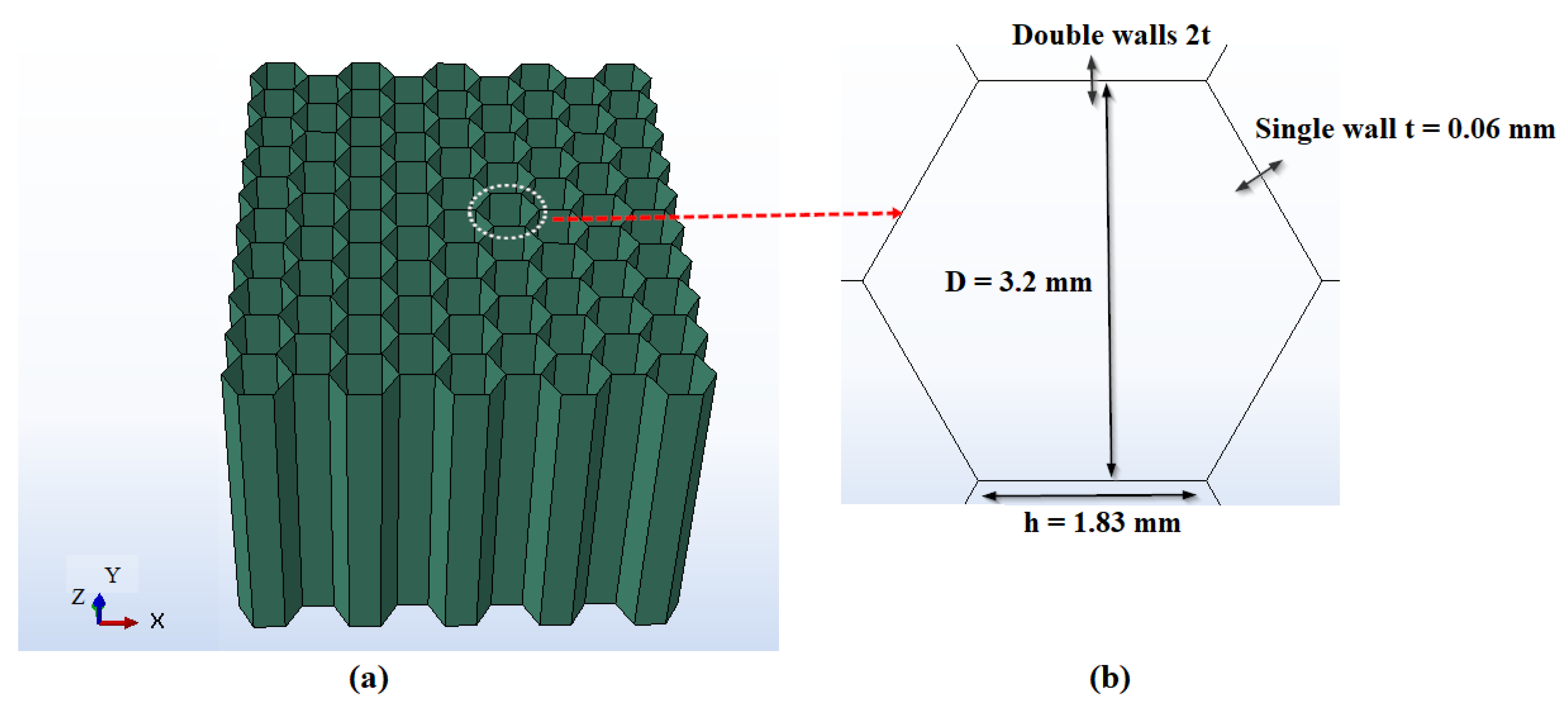
2.1. Dimensions of the Honeycomb Structure

This article examines the machining of Nomex honeycomb cores, made up of aramid fibers and phenolic resin. These structures are known for their exceptional mechanical strength, low density, and excellent thermal resistance, making them ideal for advanced industrial uses, especially in the aerospace and motorized sectors. To guarantee the accuracy of the experimental outcomes, specific and precisely defined dimensions were chosen for the Nomex honeycomb structure. The dimensions of the structure are defined by a configuration comprising 10 rows of cells in width and 19 in length (see Figure 1a). Hexagonal cells, the building blocks of the honeycomb structure, possess crucial geometric parameters that determine the density of the honeycomb structure. The specific dimensions of each cell are detailed in Figure 1b.

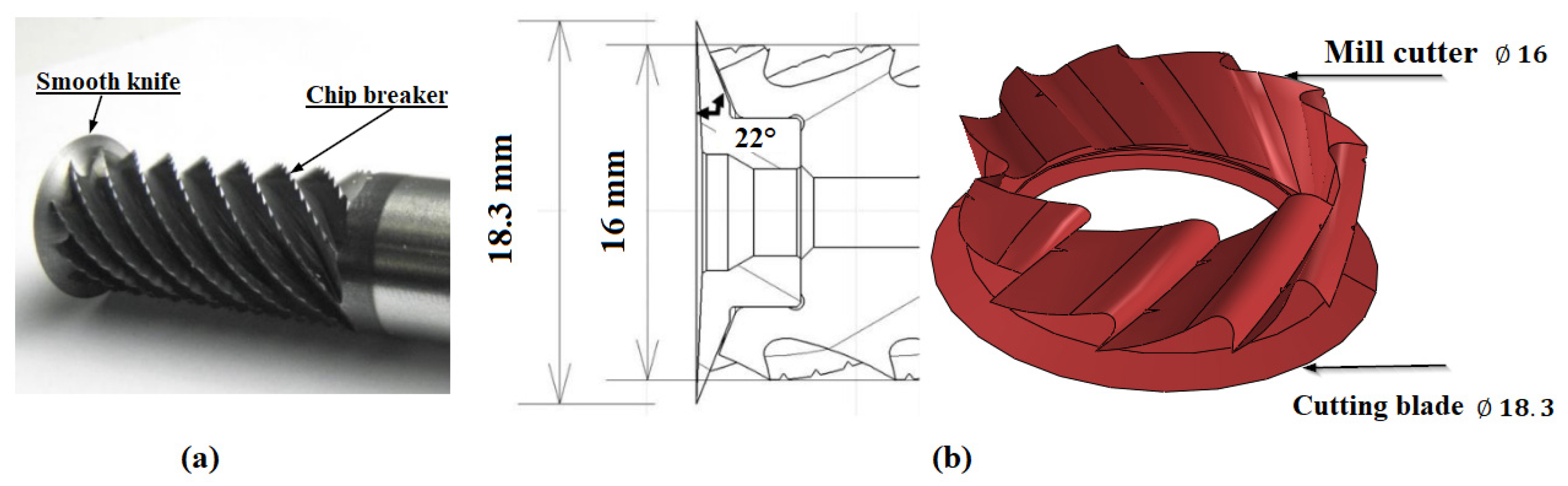
2.2. Dimension and Characteristics of the Cutting Tool

Due to the brittleness of Nomex paper, which is used in sandwich structures, its milling requires specialized tools and precise design to avoid material degradation. Machining the Nomex honeycomb core presents unique tests due to its tendency to fracture under standard mechanical stresses. Thus, the tool adopted is the CZ10 combined tool, a prototype designed according to the specifications established by the company EVATEC Tools- Thionville-France, specifically adapted to the requirements of machining complex honeycomb structures (see Figure 2a) [24]. This tool consists of two main elements: A tungsten carbide conical disc with a diameter of 18.3 mm, a cutting angle of 22° and a flank angle of 2.5°. The upper part of the tool is a cylindrical body made of high-speed steel with a diameter of 16 mm, consisting of ten helices containing chip breakers. The upper section of the tool features a ten-helix cutter with chip breakers, designed to aid in debris removal and minimize vibrations, thereby enhancing the machining process (see Figure 2b).

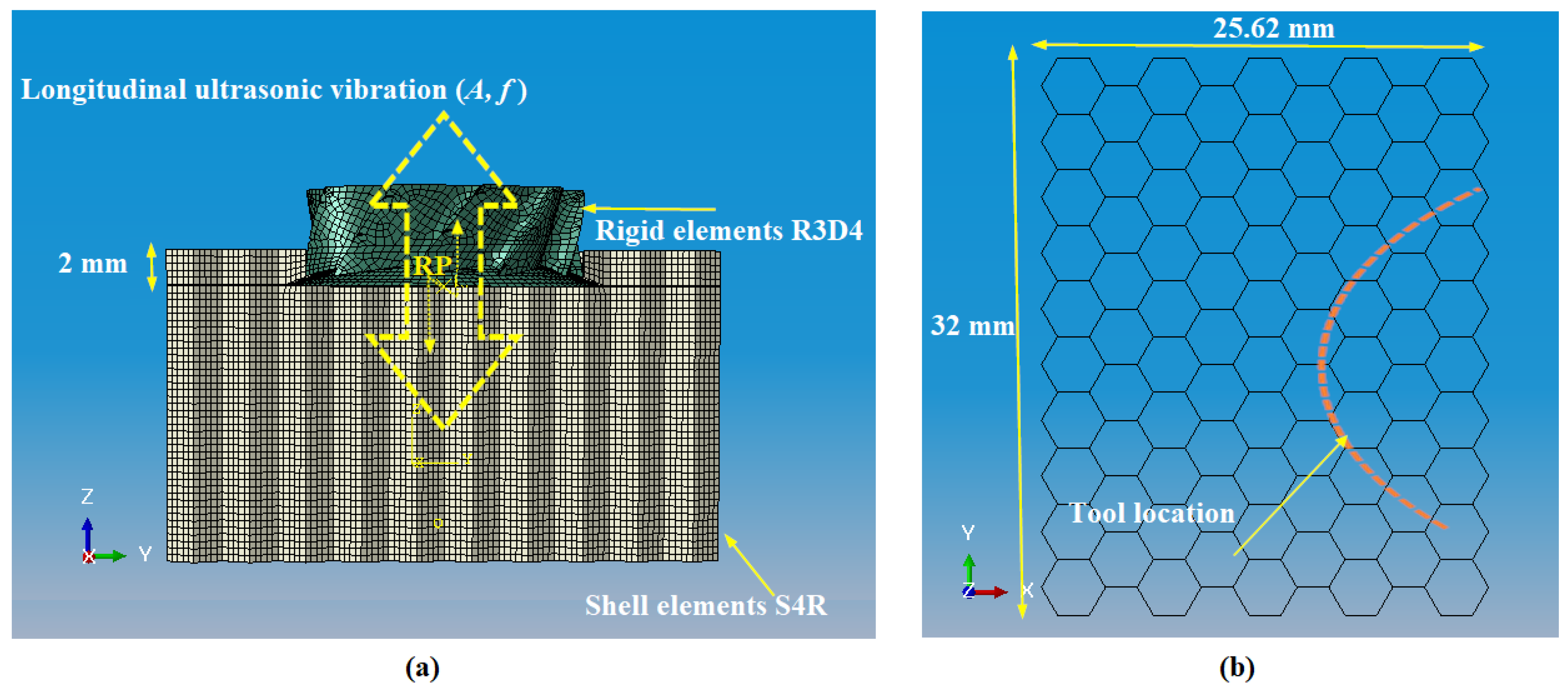
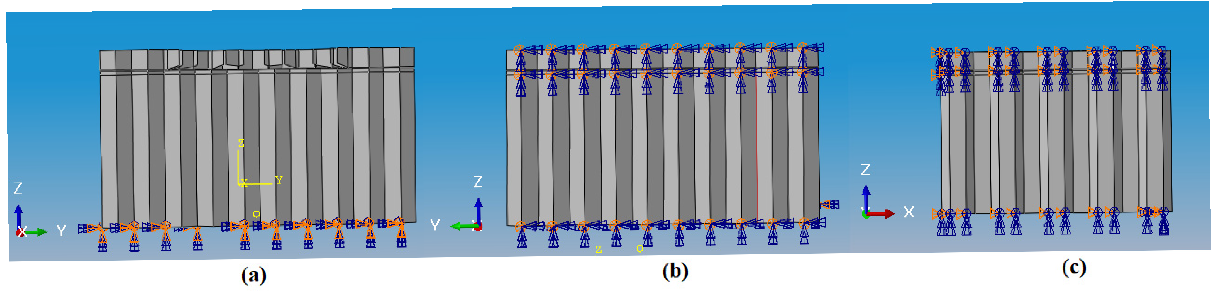
3. Finite Element Modelling

This work presents the modeling of the milling procedure of Nomex honeycomb alveolar core, performed by longitudinal–torsional machining assisted by ultrasonic vibrations. The objective of this method is to improve the efficiency of the cutting process while reducing the risk of structural deterioration and preserving the durability of the cutting tool. The simulation was carried out using a three-dimensional numerical model developed with Abaqus/Explicit software. This model offers a precise depiction of the intricate interactions between the cutting tool and the thin walls of the honeycomb structure, enabling a thorough examination of the cutting process. The Nomex honeycomb structure used in this study is composed of single and double walls, with respective thicknesses of 0.06 mm and 0.12 mm, in agreement with the conditions of the experiment. This shape incorporates the geometric and mechanical properties of the material, enabling a realistic simulation of the structure’s performance during the cutting process. For the modeling of the Nomex core, the thin walls are discretized using four-node S4R shell elements, providing reduced integration (See Figure 3a). Given the delicate nature of the Nomex paper, the cutting tool remains unaffected by deformation while milling. Therefore, in numerical modeling, the tool is considered rigid. The cutting tool modeling was carried out using four-node quadrangular rigid elements (R3D4), as shown in Figure 3a. Indeed, a mesh that is too coarse can lead to untrustworthy results, though permitting a fast calculation time. Conversely, a very fine mesh, although offering more accurate results, results in considerably longer calculation times. It is, therefore, essential to find an optimal compromise between the precision of the results and a reasonable calculation time. To find an optimal balance between accuracy and efficiency of results, a mesh size of 0.4 mm was selected. This size ensures robust results without compromising simulation performance. The adopted mesh size allowed the tool and the structure to be subdivided into fine elements, totaling 13,348 elements. Two types of interactions were integrated into the simulation of the machining process. The first concerns the contact between the cutting tool and the walls of the structure throughout its motion. The second takes into account the contact between the walls following their bending, along with the contact between the chip and the unprocessed walls. This approach makes it possible to realistically simulate friction phenomena in the contact zone while guaranteeing the numerical consistency essential for complicated simulations. A dynamic friction coefficient of 0.1 was designated to model the effects of ultrasonic vibrations applied to the cutting tool, due to the point interaction between the tool and the thin walls of the structure. This selection enables a more accurate simulation of the impact of ultrasonic vibrations on friction phenomena, taking into account the punctual nature of the interaction. To safeguard continuous contact between the tool and the part, a first integration was carried out, taking into consideration the specific geometric characteristics of the Nomex honeycomb core and the CZ10 tool (see Figure 3b). The boundary conditions were established based on the experimental configuration that was validated. In this context, the part is detained on both sides by clamps and fixing bars [24]. Symmetry conditions are imposed on the honeycomb walls around the Y plane (Uy = URx = URz = 0), simulating the restraining effect of the bars and preventing any motion in the Y direction (see Figure 4b). Also, additional symmetry conditions are applied around the X-plane (Ux = URy = URz = 0) on the surface perpendicular to the X-direction (see Figure 4c). Additionally, the workpiece is clamped to the machining table by its underside, thus blocking any motion throughout milling, and a clamping constraint (Ux = Uy = Uz = URx = URy = URz = 0) is applied to eliminate any deformation resulting by sliding (see Figure 4a).
Longitudinal–torsional ultrasonic vibration-assisted milling consists of a complex combination of motions. First, the classical tool movement undergoes a rotational movement around the Z axis, at a spindle speed n. This motion allows the tool to penetrate the structure and remove material in the traditional way. In parallel, a translational motion of the tool is applied along the X axis. This motion is controlled by the feed rate Vf, determining the progression of the tool through the part (Figure 5a). Adding longitudinal ultrasonic vibrations improves the process by introducing an additional component (Figure 3a). These vibrations, applied along the Z axis, reduce direct contact between the tool and the workpiece while generating high-frequency oscillations that reduce friction, thus optimizing material removal and increasing the efficiency of the cutting process. Additionally, a torsional motion is applied, generating additional vibrations around the Z axis (Figure 5a,b). These vibrations cause a rotary motion of the tool, resulting in a torsional oscillation that is superimposed on the classic rotation of the tool. This motion, coupled with longitudinal vibrations, produces a helical effect, where the tool moves in a spiral manner through the material. In order to simulate this process precisely, a reference point, designated RP, is placed on the axis of revolution of the cutting tool (see Figure 5b). This point plays a crucial role in correctly assigning the cutting parameters and assessing the applied forces. Longitudinal–torsional ultrasonic vibration-assisted cutting can be seen as a hybridization of the traditional cutting process, where a cutting tool is subjected to longitudinal ultrasonic vibrations along its axis, while being subjected to torsional vibrations that follow the direction of rotation of the tool. Accordingly, the trajectory of the disc tool movement during this longitudinal–torsional ultrasonic vibration-assisted cutting process can be expressed as follows [24]:
x 1 t = V f t + r   c o s ( 2 π n t 60 + A   s i n 2 π f t ) y 1 t = r   s i n ( 2 π n t 60 + A   s i n 2 π f t ) z 1 t = A sin 2 π f t + φ 0
where A represents the amplitude of longitudinal and torsional vibrations, expressed in (m). Since these two types of vibrations are generated by the same excitation, they oscillate at the same ultrasonic frequency, noted f and spoken in hertz (Hz). φ0 designates the phase shift among longitudinal and torsional vibrations, expressed in radians (Rad). r characterizes the radius of the tool, expressed in (m), n is the spindle speed expressed in (rpm), Vf to the feed rate, expressed in (m/s) and t is the time, expressed in seconds (s). In all the numerical simulations conducted, the frequency is set to 21.06 kHz, and the vibration amplitude is maintained at 25 µm.

4. Material Characteristics, Degradation Mechanisms and Failure Criteria

Nomex paper, used for the manufacture of honeycomb structures, is composed of aramid fibers and phenolic resin [25]. As long as the aramid fibers are not uniformly distributed, the actual behavior of Nomex paper is characterized by anisotropy, which justifies orthotropic modeling. Indeed, the orthotropic approach requires the definition of local reference points for each direction of the hexagonal cells of the honeycomb, in order to take into account, the distinct mechanical properties in each direction. However, due to the increased complexity of the orthotropic model, many numerical works have chosen to model Nomex paper as an isotropic material [26]. This simplification allows for the reduction of CPU computation time requirements while providing a satisfactory estimation of material performance in many cases. Thus, this study favored the adoption of the isotropic elastoplastic approach, recognized for its simplicity of implementation and its low cost in terms of CPU calculation time. This approach not only significantly reduces the computational resources required but also provides a sufficiently accurate approximation of the results, while maintaining an adequate representation of the mechanical behavior of the material in the simulations. In this study, Nomex paper is modeled as an isotropic elastoplastic material, with mechanical properties defined in Table 1 [1,3]. Failure criteria are defined based on the fundamental mechanical properties of the material [1,3]. In this context, a failure criterion based on shear is applied, utilizing the theory of maximum shear strain. This phenomenon was modeled using Abaqus software, renowned for its advanced finite element analysis capabilities. As the tool advances through the material, the Nomex paper’s breakage is dictated by its plastic deformation. When this deformation reaches critical thresholds of 0.0628 and 0.1208 for single and double thicknesses, respectively, the damaged element is removed, resulting in the initiation of chip formation. This chip formation process is activated as soon as the damage coefficient, denoted d, reaches a critical value of 1, in accordance with the expression given in Equation (2). This threshold marks the transition to irreversible degradation of the material and the beginning of the chip formation process.
d = Δ ε ε f
In this expression, ∆ε represents the increment of the equivalent plastic strain, while εf refers to the equivalent strain at the time of failure.
Understanding cutting forces is essential for assessing both machining quality and machine tool performance. These forces are essential for sizing machine components, assessing the deformations of processed parts, and examining the chip formation process, with consideration of the material’s mechanical properties. The cutting force and its components are presented as follows [9,27]:
F x = 1 t 2 t 1   t 1 t 2 F C X d t
F y = 1 t 2 t 1   t 1 t 2 F C Y d t
F z = 1 t 2 t 1   t 1 t 2 F C Z d t
F A v g = F x 2 + F y 2 + F z 2
The quantities FAvg, Fx, Fy and Fz correspond to the cutting force and its components along the X, Y and Z axes, expressed in newtons (N). Similarly, FCX, FCY and FCZ represent the instantaneous components of this force, also evaluated in newtons (N). The instants t1 and t2 mark the beginning and end of the cutting process, respectively, and are expressed in seconds (s).

5. Results and Discussions

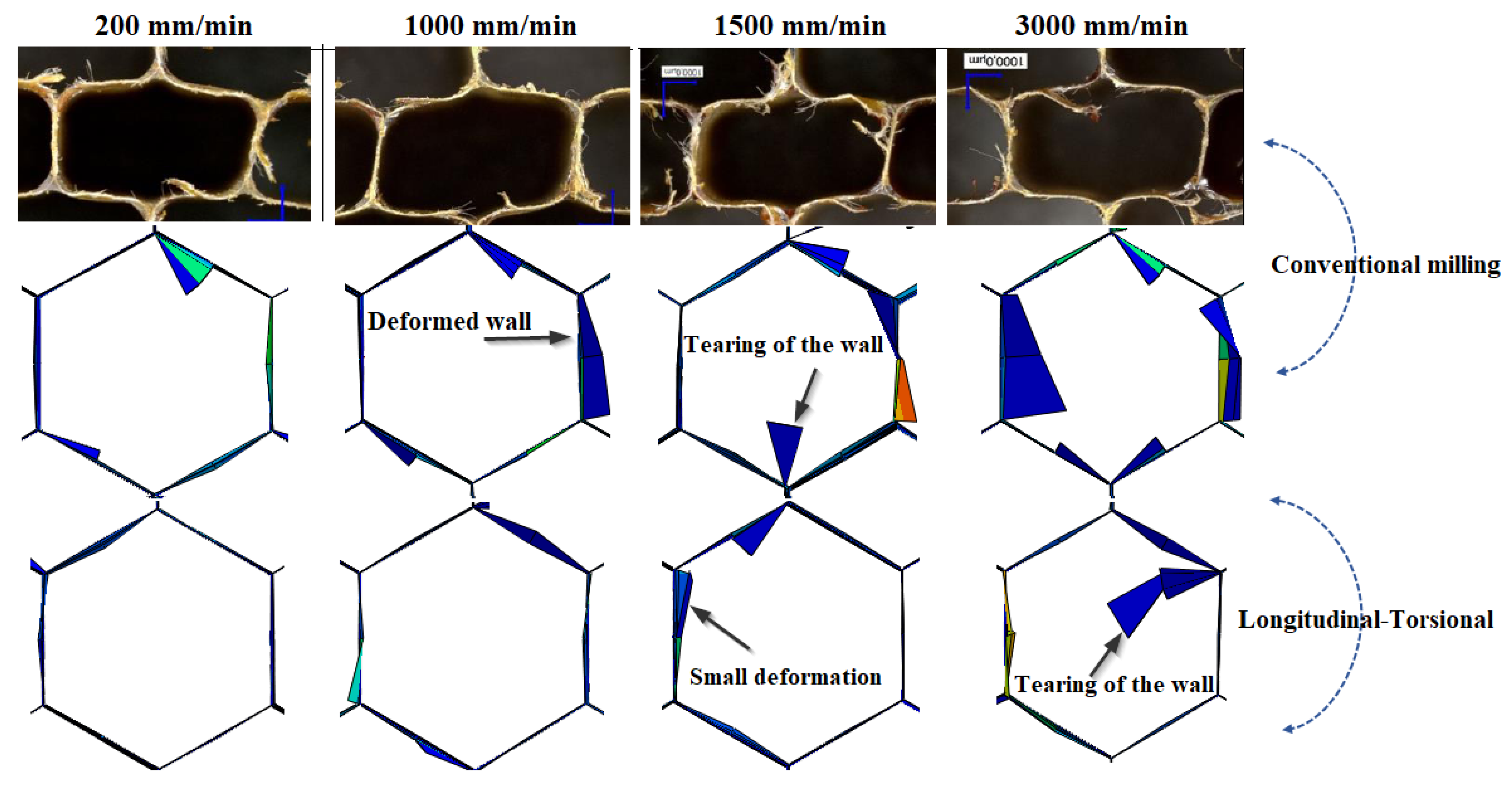
5.1. Analysis of Surface Defects as a Function of Feed Rate

Machining Nomex honeycomb structures poses a major technical challenge, mainly due to the difficulty of the mechanical interactions between the cutting tool and the material. These interactions, the modeling of which is particularly complex, generate various machining defects such as deformations, tears and the presence of uncut fibers, thus affecting the quality of the finished surface. This study analyzes the influence of the feed rate on the quality of the machined surface by carrying out a detailed evaluation of the results from numerical simulations and those obtained during experimental tests carried out in conventional milling. Furthermore, this study also integrates the performance evaluation of longitudinal–torsional milling assisted by ultrasonic vibrations, in order to explore its influence on the improvement of surface quality under the same cutting conditions used. In this context, four feed rates, ranging from 200 to 3000 mm/min, were examined, with the rotation speed being fixed at 23,000 rpm constantly. The obtained results from numerical simulations and experimental tests are presented and compared in Figure 6.
The results in Figure 6 show that the surface quality deteriorates as the feed rate increases, both in experiments and in numerical modeling. Regarding conventional cutting, at a low feed rate (200 mm/min), the wall deformation is minimal, resulting in a relatively good surface quality, with slight wall deformation. However, as the feed rate approaches 1000 mm/min, signs of tearing appear on the walls, leading to progressive deterioration of the surface. This trend becomes more pronounced at 1500 mm/min, where wall tearing becomes more pronounced and larger deformations are observed. At around 3000 mm/min, the surface quality is severely impaired, with significant tearing and deformation on the walls, indicating a loss of control of the high-speed cutting process. In a conventional machining process, increasing the feed rate leads to a gradual degradation of surface quality. This phenomenon is mainly due to the increase in cutting forces, which leads to deformation and tearing. The introduction of longitudinal–torsional ultrasonic vibrations into a machining process allows a significant improvement in surface quality, especially at high feed rates. In this context, longitudinal–torsional ultrasonic vibrations profoundly modify the interactions between the cutting tool and the workpiece, playing a key role in reducing friction in the cutting zone. These vibrations, which combine high-frequency longitudinal and torsional movements, generate regular micro-impacts on the surface of the material. These micro-impacts create a localized peeling effect of the surface layers of the material, facilitating their removal in a more controlled manner and improving the overall efficiency of the cutting process. Longitudinal vibrations, which act mainly on the normal force applied to the surface of the part and reduce the stresses that cause plastic deformations in the material, thus limiting the risk of damage to the surface. This reduction in stresses helps maintain the integrity of the machined part, particularly for materials sensitive to deformation. Furthermore, torsional vibrations induce a rotational movement at the interface between the tool and the material, promoting sliding between the material layers. This reduces the resistance to the movement of material particles and makes the cut smoother, reducing the force required to remove material. The present model accurately predicts major machining defects, such as uncut fibers, localized deformations, and tears, validating its effectiveness in simulating material degradation mechanisms. However, minor differences remain in complex areas, such as junctions, where modeling mechanical effects remains a challenge, requiring improvements to better simulate these specific effects. It is also important to note that this study has some limitations. In particular, burrs were not considered, as the current numerical modeling relies on S4R shell elements for the walls, which prevents a detailed analysis of this phenomenon. However, despite this limitation, a thorough comparison of the simulation results with experimental data [24] showed good agreement, thus confirming that the model is valid and reliable in simulating the overall behaviors of the machining process, while highlighting areas where improvements can be made to increase its accuracy.

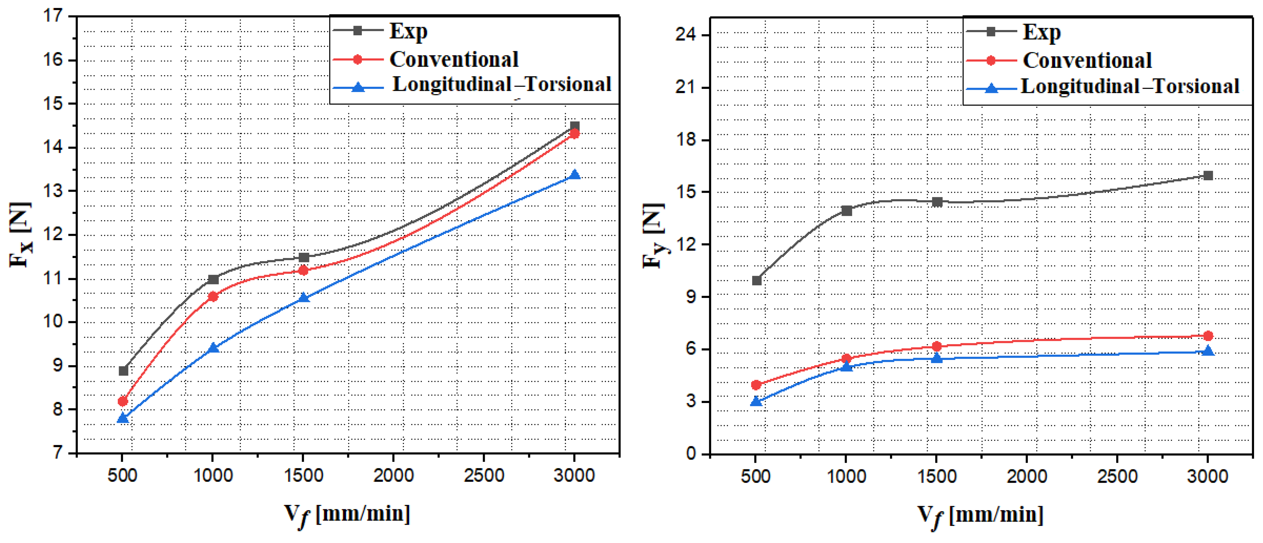
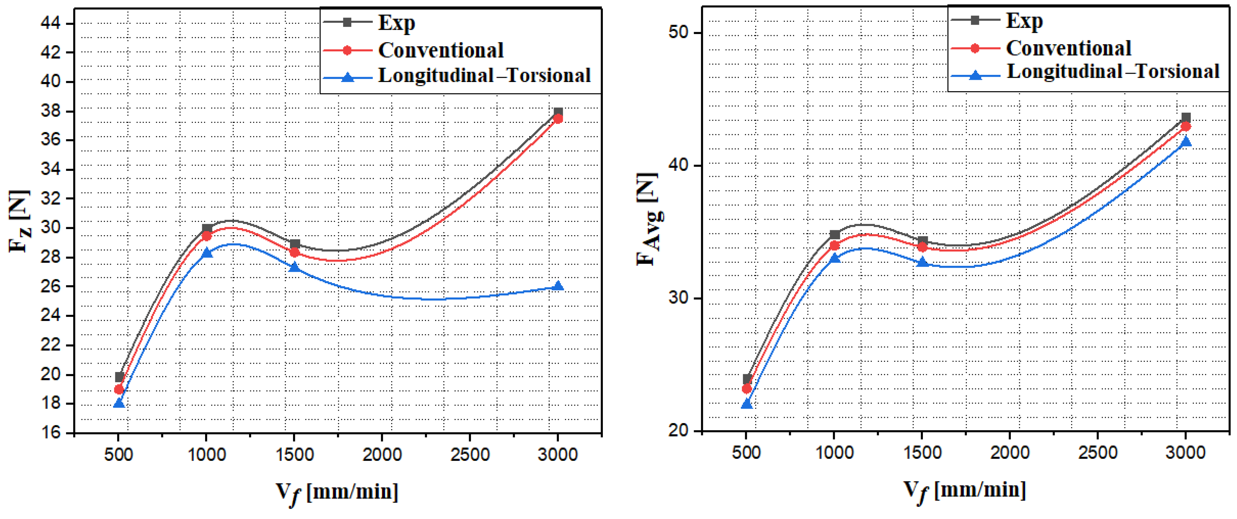
5.2. Comparative Analysis of Conventional and Longitudinal–Torsional Machining: Impact of Feed Rate on Cutting Force and Its Components

This section presents a series of numerical simulations carried out to compare conventional milling and milling assisted by longitudinal–torsional ultrasonic vibrations, in the context of shaping Nomex honeycomb cores. The principal aim of this study is to examine the effect of diverse feed rates, varying from 200 to 3000 mm/min, on the cutting force and its components in the three spatial directions. A detailed comparative analysis was also conducted between the obtained results from numerical simulations and those from experimental tests performed in conventional milling [24]. Cutting parameters were kept constant during the simulations, with the rotation speed fixed at 2000 rpm. The comparative results between conventional machining and ultrasonic vibration-assisted longitudinal–torsional machining are shown in Figure 7 and Figure 8.
The results presented in Figure 7 and Figure 8 show that the evolution of the cutting force and its components as a function of the feed rate follows a behavior similar to that observed for composite materials [27]. Indeed, a significant increase in the cutting force and its components is observed as the feed rate increases. Regarding the feed component Fx, conventional machining results in a progressive increase in the cutting force, going from 8 N to approximately 15 N when the feed rate varies between 500 mm/min and 3000 mm/min. Ultrasonic vibration-assisted machining can significantly reduce the Fx component, particularly at feed rates above 500 mm/min, where a 20% reduction is observed around 3000 mm/min. In this range, ultrasonic vibrations decrease the friction between the tool and the workpiece, thus facilitating tool engagement and optimizing the efficiency of the cutting process. Regarding the lateral component Fy, a notable divergence from the experimental results was observed. This divergence, which can reach a variation rate of 60%, is mainly attributed to the removal of damaged elements and the loss of contact between the tool and the material. In this regard, the lateral component Fy remains relatively stable during conventional machining, fluctuating between 3 N and 6 N, with small variations depending on the feed rate. The integration of longitudinal–torsional ultrasonic vibrations results in a notable reduction of the lateral force Fy, especially at high feed rates. This reduction, which reaches approximately 10% at a speed of 3000 mm/min compared to conventional milling, can be mainly attributed to the optimization of the geometry of the cutting tool, which is equipped with helices on the cutter edges, thus facilitating chip evacuation. The crushing component Fz is twice as large as the feed component Fx, which reflects the resistance of the Nomex honeycomb structure to out-of-plane loading [28]. However, in the context of shaping by mechanical manufacturing processes, this characteristic becomes unfavorable when milling the honeycomb structure, as it leads to significant deformation of the walls, thus compromising the surface quality. In conventional milling, the crushing force Fz increases with feed rate, reaching approximately 38 N at 3000 mm/min. On the other hand, in ultrasonic vibration-assisted machining, this force decreases considerably, being reduced to 26 N at the same speed, a reduction of 30%. This decrease is explained by the attenuation of vertical forces due to ultrasonic vibrations, which generate tool oscillations and reduce the adhesion between the tool and the material, thus optimizing cutting efficiency and reducing the energy required for the process. Thus, the average force FAvg evolves in a similar way to that of its components Fx and Fz, increasing progressively with the feed rate for both processes. The results reveal that ultrasonic vibration-assisted machining offers significant advantages over conventional machining. This method allows a substantial reduction in cutting forces in all directions, particularly for Fz and FAvg components, with reductions ranging from 20% to 40% depending on the force direction. These improvements, attributed to reduced friction, optimized tool geometry and the effectiveness of ultrasonic vibrations, demonstrate the effectiveness of this technology for machining composite materials. The same observations were reported by Ahmad et al. in their experimental studies on milling of Nomex honeycomb structure, using UCK and UCSB cutting tool [9]. The comparison of numerical and experimental results in conventional machining shows a strong correspondence, thus validating the reliability of the numerical model. This concordance confirms the model’s ability to predict mechanical behaviors during machining and its applicability in real conditions.

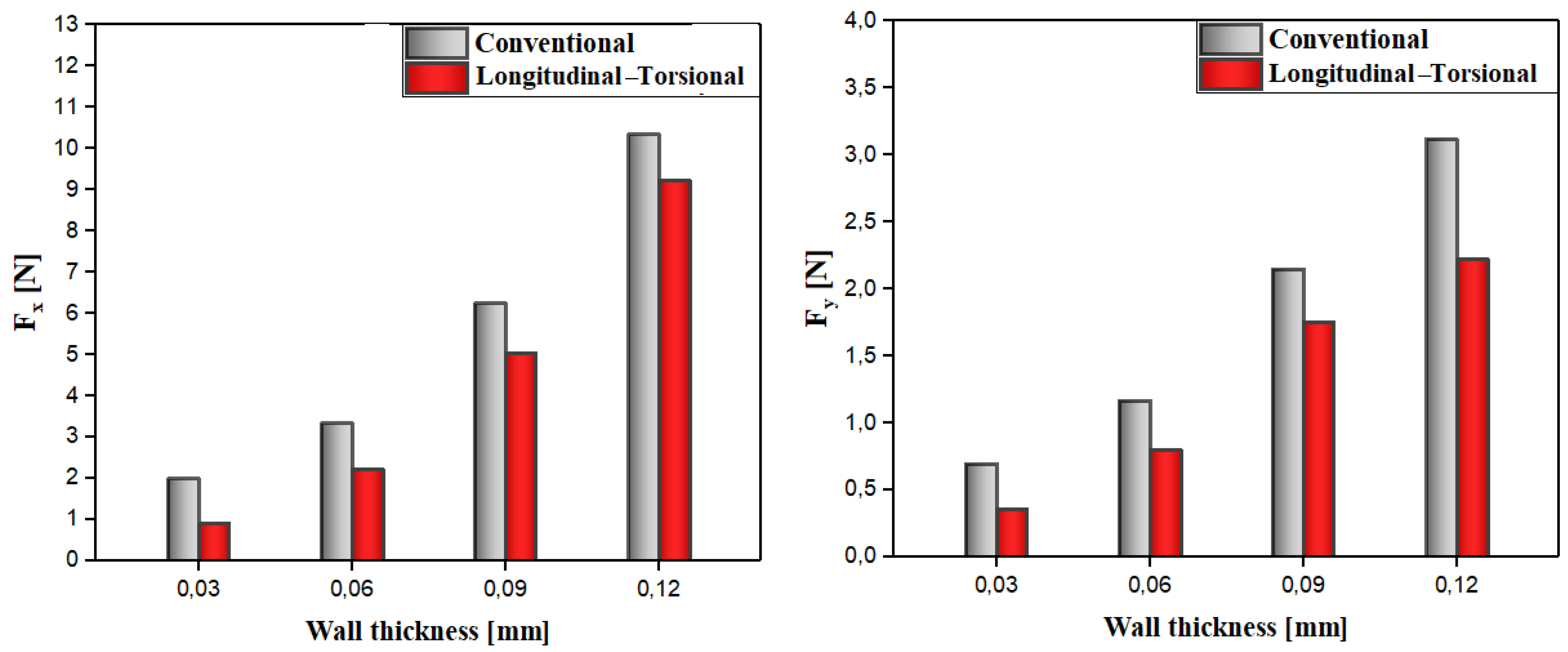
5.3. Comparative Analysis of Conventional and Longitudinal–Torsional Machining: Impact of Wall Thickness on Cutting Force and Its Components

Machining complex structures, such as Nomex honeycombs, presents particular challenges, particularly due to the extremely thin walls, which directly impact the cutting force components. Wall thickness is a major challenge in the manufacturing of this type of structure, as it can compromise machining quality. This can lead to problems such as material buildup on the cutting edges, forming clumps that accelerate premature tool wear, especially when the wall thickness is significant. This study numerically analyzes the impact of wall thickness on cutting force and its components, comparing conventional machining and ultrasonic vibration-assisted longitudinal–torsional machining. The simulations, carried out with wall thicknesses ranging from 0.03 mm to 0.12 mm, use a feed rate of 3000 mm/min and rotation at 2000 rpm. The obtained results are available in Figure 9 and Figure 10.
The results presented in Figure 9 and Figure 10 indicate that the feed force Fx, which characterizes the resistance to the tool entering the material, increases with the wall thickness in both processes studied. In conventional machining, this force increases significantly with the wall thickness, reaching significantly higher values for a thickness of 0.12 mm. This trend is mainly attributed to the increased strength of thicker walls, which generate greater friction and exert forces opposing the tool feed. On the other hand, in the case of longitudinal–torsional machining assisted by ultrasonic vibrations, a significant reduction in feed force is observed, particularly for a thickness of 0.12 mm. This decrease can be explained by the reduction in friction between the tool and the part, facilitated by ultrasonic vibrations, which optimizes tool entry and chip evacuation, thus resulting in a reduction in cutting forces in this direction. The side cutting component Fy increases with wall thickness, especially above 0.06 mm, due to the high density of Nomex paper. This increased resistance hinders tool penetration and requires strict force control to optimize the machining process, limit tool wear and improve the quality of the machined part. However, the introduction of longitudinal–torsional ultrasonic vibration-assisted machining results in a significant reduction of the cutting component Fy. This phenomenon is explained by the attenuation of continuous contact between the tool and the material, induced by ultrasonic vibrations. Indeed, these vibrations create contact-detachment cycles between the tool and the material, thus reducing friction and cutting resistance. This dynamic interaction generates a smoother cut with less stress on the tool, which not only contributes to a discount in lateral cutting force but also to an improvement in the quality of the machined part and an extension of tool life. The crushing force Fz, which measures the vertical resistance exerted by the tool, follows a similar trend in both processes. In conventional machining, it increases considerably with wall thickness, reaching 38 N at 0.12 mm. In contrast, longitudinal–torsional machining assisted by ultrasonic vibrations reduces this force by from 30 to 40% compared to conventional machining, thanks to a reduction in friction between the tool and the material, thus facilitating the cutting action and reducing vertical resistance. The evolution of the cutting force in all directions, as a function of the wall thickness, is dictated by various physical and mechanical factors. As the wall thickness increases, the resistance of the material increases, which generates premature wear of the cutting tool. Therefore, the use of longitudinal–torsional milling assisted by ultrasonic vibrations allows a significant reduction in cutting force. This reduction results from the reduction of continuous contact between the tool and the material, facilitated by ultrasonic vibrations, which promotes smoother cutting and reduces friction. Therefore, it is essential to consider wall thickness in order to optimize the cutting tool and improve surface quality.

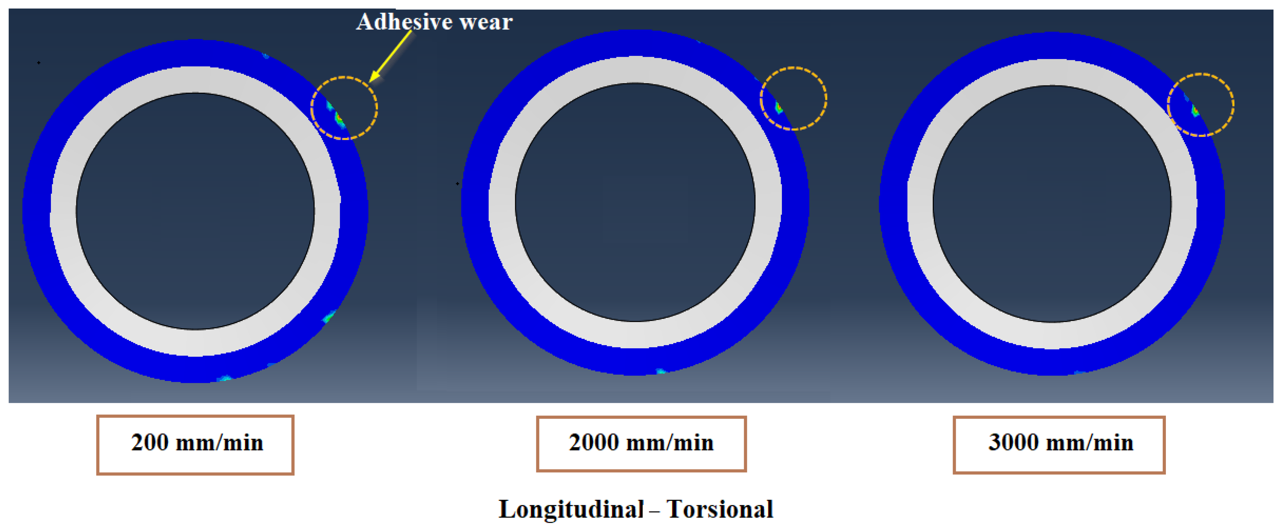
5.4. Comparative Analysis of Conventional and Longitudinal–Torsional Machining: Impact of Feed Rate on Cutting Tool Wear

When machining composite materials, several wear mechanisms can impair tool performance, including chipping, flank wear and adhesive wear. Unlike previous work that emphasizes the predominance of abrasive wear, the results of the present study highlight the predominance of adhesive wear. This mechanism is mainly due to mechanical interactions between the tool and the machined part, promoting the formation of localized adhesives. The rupture of these adhesion zones causes material to be torn off the surface of the tool, thus accelerating its wear. Tests carried out on the Nomex honeycomb material revealed the accumulation of a yellowish dust on the CZ10 combination tool (knife and shredder), attributed to thermal or mechanical degradation of the phenolic resin impregnating the aramid paper (Figure) [24]. Similar phenomena are reported during the machining of other laminated composites, notably CFRP composites, where resin and carbon fiber residues also accumulate on the active areas of the tools [29]. Furthermore, the morphology of the chips generated during Nomex machining depends strongly on the cutting conditions. At high feed speeds, the chips are voluminous, while, at low feed speeds, they fragment into fine, powdery microchips. This morphological evolution directly influences wear by adhesive, as well as the quality of the processed surface and the stability of the process. Indeed, the circular knife used in milling is subjected to high mechanical stresses, accelerating its wear. Therefore, it is crucial to precisely refine the cutting criteria to ensure optimal performance of the cutting process and protect the cutting tool. This study analyzes the influence of adhesive wear by comparing the performance of conventional milling and hybrid milling assisted by ultrasound and vibration. The observation of cutting tool wear induced by contact pressure during machining forms the basis of the analysis. The contact pressure distribution is analyzed for various feed rates, ranging from 200 mm/min to 3000 mm/min, to evaluate adhesive wear, with a constant rotational speed of 2000 rpm. The results are shown in Figure 11 and Figure 12.
The results show that tool adhesion wear is directly influenced by rotation speed. From an experimental point of view, at low feed speeds, the chips transform into a fine powder, consisting of aramid fibers and phenolic resin, which promotes increased adhesion between the cutting tool and the material. This powder, generated by friction, intensifies tool wear by creating micro-welds between the tool and the chips, the rapid breakage of which accelerates the wear process. On the other hand, at higher feed rates, the size of the chips increases, thus reducing the formation of powder. This variation in chip morphology reduces adhesion between the tool and the material, therefore limiting the intensity of adhesion wear. From a numerical point of view, tool adhesion wear is mainly influenced by rotational speed, and this phenomenon is reflected by the distribution of contact pressure at the cutting tool stop. At low feed speeds (200 mm/min), the adhesion between the tool and the material is more pronounced, as the chips generated are finer and tend to transform into a fine powder. This powder, composed of aramid fibers and phenolic resin, promotes the formation of micro-welds between the tool and the chips, which accelerates tool wear. At higher feed rates (3000 mm/min), the chips generated are larger and less likely to turn into a fine powder. The larger chip size thus reduces adhesion between the tool and the material. This change in chip morphology limits the intensity of adhesive wear, because less friction is generated between the tool and the machined material. On the other hand, the integration of longitudinal–torsional ultrasonic vibrations in machining processes makes it possible to reduce permanent contact between the tool and the material, thus minimizing friction. This limits adhesive wear, which occurs in the form of micro-welds between the tool and the chips, especially at low cutting speeds. Ultrasonic vibrations cause micro-oscillation of the tool, disrupting contact and reducing contact time, which reduces friction and adhesion. This technology also reduces the formation of fine chips and powder, which are responsible for increasing tool wear. Improving the thermal stability of the cutting process allows for better control of chip formation, thus extending tool life. Ultrasonic vibrations also change the dynamics of the machining process. They allow for better control of machining forces, especially when cutting hard materials, thus reducing the risk of premature tool failure. This approach improves cutting performance while preserving tools, which represents an advantage in optimizing industrial processes. Ultimately, the use of longitudinal–torsional ultrasonic vibrations is a significant technological advance, reducing adhesive wear. It improves tool durability, machining quality and manufacturing process accuracy, providing major benefits for industries where tool wear management and maintenance cost reduction are priorities.

6. Conclusions

This study focuses on the cutting of Nomex honeycomb alveolar composite core, combining conventional machining methods and the ultrasonic vibration-assisted longitudinal–torsional milling. A 3D numerical model, developed using Abaqus/Explicit software and validated by experimental tests, simulates the impact of feed rate on cutting force and their components in the three directions, as well as on the surface condition and wear of the cutting tool for the different processes. This approach allows for a better understanding of the interactions between these parameters, thus contributing to the optimization of machining processes for complex composite materials. The main results are presented below:
  • The integration of longitudinal torsional vibrations made it possible to reduce cutting force in all directions, with reductions ranging from 20% to 40%, particularly for the Fz and Fx components.
  • At high feed rates, the ultrasonic vibration-assisted longitudinal–torsional milling process reduces adhesive wear, thus enabling a cleaner cut and increased tool durability, unlike conventional milling, which promotes adhesive wear, especially at low feed rates.
  • The integration of the new longitudinal–torsional milling technology into the CZ10 combined cutting tool significantly improves the efficiency of the milling process, thus providing a more robust, precise and efficient solution, meeting the demanding standards of the industrial sectors.
  • Surface defects, such as tears and deformations, are significantly reduced with ultrasonic vibration-assisted machining. This method maintains superior surface quality even at high feed rates (3000 mm/min), unlike conventional machining, where surface quality deteriorates rapidly under similar conditions.
  • In order to improve the simulation of the interaction between the cutting tool and the structure, it would be necessary to replace the S4R shell elements with solid elements in the cutting zone, thus allowing a more accurate simulation of the burrs.

Author Contributions

T.Z. performed analysis, created the methodology, interpreted data and results, and was a major contributor to writing the manuscript. J.-E.S. performed analysis, interpreted data and results, and was a major contributor to writing the manuscript, investigation. M.N. contributed to the supervision, methodology, and investigation; performed analysis, interpreted data and results, and was a contributor to writing the manuscript. M.B. interpreted the results and was a major contributor to writing the manuscript. All authors have read and agreed to the published version of the manuscript.

Funding

This research received no external funding.

Institutional Review Board Statement

Not applicable.

Informed Consent Statement

Not applicable.

Data Availability Statement

Data are contained within the article.

Conflicts of Interest

The authors declare no conflicts of interest.

References

  1. Foo, C.C.; Chai, G.B.; Seah, L.K. Propriétés mécaniques du matériau Nomex et de la structure alvéolaire Nomex. Compos. Struct. 2007, 80, 588–594. [Google Scholar] [CrossRef]
  2. Ahmad, S.; Zhang, J.; Feng, P.; Yu, D.; Wu, Z.; Ma, K. Technologies de traitement des composites alvéolaires Nomex (NHC): Revue critique. Compos. Struct. 2020, 250, 112545. [Google Scholar] [CrossRef]
  3. Roy, R.; Park, S.-J.; Kweon, J.-H.; Choi, J.-H. Caractérisation des propriétés mécaniques des matériaux constitutifs de l’âme alvéolaire Nomex. Compos. Struct. 2014, 117, 255–266. [Google Scholar] [CrossRef]
  4. Liu, Y.; Liu, W.; Gao, W. Out-of-plane shear property analysis of Nomex honeycomb sandwich structure. J. Reinf. Plast. Compos. 2021, 40, 165–175. [Google Scholar] [CrossRef]
  5. Li, W.; Qiu, C.; Li, Z.; Nie, H. Un critère de rupture pour les structures en nid d’abeilles prenant en compte l’apparition d’instabilité sous charges hors plan. J. Sandw. Struct. Mater. 2020, 425586206. [Google Scholar]
  6. Zarrouk, T.; Salhi, J.E.; Nouari, M.; Bouali, A. Enhancing the Machining Performance of Nomex Honeycomb Composites Using Rotary Ultrasonic Machining: A Finite Element Analysis Approach. Materials 2024, 17, 2044. [Google Scholar] [CrossRef]
  7. Mughal, K.H.; Qureshi, M.A.M.; Jamil, M.F.; Ahmad, S.; Khalid, F.A.; Qaiser, A.A.; Maqbool, A.; Raza, S.F.; Zhang, J. Investigation of hybrid ultrasonic machining process of Nomex honeycomb composite using a toothed disc cutter. Ultrasonics 2024, 141, 107343. [Google Scholar] [CrossRef]
  8. Zarrouk, T.; Nouari, M.; Salhi, J.E.; Essaouini, H.; Abbadi, M.; Abbadi, A.; Lahlaouti, M.L. In-Depth Analysis of the Processing of Nomex Honeycomb Composites: Problems, Techniques and Perspectives. Machines 2024, 12, 561. [Google Scholar] [CrossRef]
  9. Ahmad, S.; Zhang, J.; Feng, P.; Yu, D.; Wu, Z. Experimental study on rotary ultrasonic machining (RUM) characteristics of Nomex honeycomb composites (NHCs) by circular knife cutting tools. J. Manuf. Process. 2020, 58, 524–535. [Google Scholar] [CrossRef]
  10. Daud, S.Z.M.; Lim, J.; Amir, M.; Kim, S.W. Enhancing impact energy absorption in composite sandwich structures through synergistic smart material integration. Results Eng. 2024, 21, 101902. [Google Scholar] [CrossRef]
  11. Yang, C.; Huo, Y.; Meng, K.; Zhou, W.; Yang, J.; Nan, Z. Fatigue failure analysis of platform screen doors under subway aerodynamic loads using finite element modeling. Eng. Fail. Anal. 2025, 174, 109502. [Google Scholar] [CrossRef]
  12. Xu, P.; Guo, W.; Yang, L.; Yang, C.; Zhou, S. Crashworthiness analysis and multi-objective optimization of a novel metal/CFRP hybrid friction structures. Struct. Multidiscip. Optim. 2024, 67, 97. [Google Scholar] [CrossRef]
  13. Jiang, E.; Yue, Q.; Xu, J.; Fan, C.; Song, G.; Yuan, X.; Ma, Y.; Yu, X.; Yang, P.; Feng, P.; et al. A wear testing method of straight blade tools for Nomex honeycomb composites machining. Wear 2024, 546, 205325. [Google Scholar] [CrossRef]
  14. Xu, J.; Yue, Q.; Zha, H.; Yuan, X.; Cai, X.; Xu, C.; Ma, Y.; Feng, P.; Feng, F. Wear reduction by toughness enhancement of disc tool in Nomex honeycomb composites machining. Tribol. Int. 2023, 185, 108475. [Google Scholar] [CrossRef]
  15. Zarrouk, T.; Nouari, M.; Salhi, J.E. Numerical study on rotary ultrasonic machining (RUM) characteristics of Nomex honeycomb composites (NHCs) by UCSB cutting tool. Int. J. Adv. Manuf. Technol. 2024, 132, 5351–5366. [Google Scholar] [CrossRef]
  16. Zarrouk, T.; Salhi, J.E.; Atlati, S.; Nouari, M.; Salhi, M.; Salhi, N. Study on the behavior law when milling the material of the Nomex honeycomb core. Mater. Today Proc. 2021, 45, 7477–7485. [Google Scholar] [CrossRef]
  17. Zarrouk, T.; Nouari, M.; Makich, H. Simulated Study of the Machinability of the Nomex Honeycomb Structure. J. Manuf. Mater. Process. 2023, 7, 28. [Google Scholar] [CrossRef]
  18. Zarrouk, T.; Nouari, M.; Salhi, J.E.; Abbadi, M.; Abbadi, A. Three-Dimensional Finite Element Modeling of Ultrasonic Vibration-Assisted Milling of the Nomex Honeycomb Structure. Algorithms 2024, 17, 204. [Google Scholar] [CrossRef]
  19. Liang, Y.; Feng, P.; Song, Z.; Zhu, S.; Wang, T.; Xu, J.; Yue, Q.; Jiang, E.; Ma, Y.; Song, G.; et al. Wear Mechanisms of Straight Blade Tool by Dual-Periodic Impact Platform. Int. J. Mech. Sci. 2025, 288, 110031. [Google Scholar] [CrossRef]
  20. Wang, Y.; Wang, X.; Kang, R.; Sun, J.; Jia, Z.; Dong, Z. Analysis of influence on ultrasonic-assisted cutting force of Nomex honeycomb core material with straight knife. Chin. J. Mech. Eng. 2017, 53, 73–82. [Google Scholar] [CrossRef]
  21. Cao, W.; Zha, J.; Chen, Y. Cutting force prediction and experiment verification of paper honeycomb materials by ultrasonic vibration-assisted machining. Appl. Sci. 2020, 10, 4676. [Google Scholar] [CrossRef]
  22. Zhang, X.; Dong, Z.; Wang, Y.; Xu, Z.; Song, H.; Kang, R. Charization of surface microscopic of Nomex honeycomb after ultrasonic assisted cutting. J. Mech. Eng. 2007, 53, 90–99. [Google Scholar] [CrossRef]
  23. Xiang, D.; Wu, B.; Yao, Y.; Liu, Z.; Feng, H. Ultrasonic longitudinal-torsional vibration-assisted cutting of Nomex® honey-comb-core composites. Int. J. Adv. Manuf. Technol. 2019, 100, 1521–1530. [Google Scholar] [CrossRef]
  24. Jaafar, M. Étude Expérimentale et Simulation Numérique de L’usinage des Matériaux en Nids D’abeilles: Application au Fraisage des Structures Nomex® et Aluminium. Ph.D. Thesis, Université de Lorraine, Nancy, France, 2018. [Google Scholar]
  25. Fischer, S.; Drechsler, K.; Kilchert, S.; Johnson, A. Mechanical tests for foldcore base material properties. Compos. Part A Appl. Sci. Manuf. 2009, 40, 1941–1952. [Google Scholar] [CrossRef]
  26. Nasir, M.A.; Khan, Z.; Farooqi, I.; Nauman, S.; Anas, S.; Khalil, S.; Pasha, A.; Shah, M.; Qaiser, H.; Ata, R. Transverse shear behavior of a Nomex core for sandwich panels. Mech. Compos. Mater. 2015, 50, 733–738. [Google Scholar] [CrossRef]
  27. Jenarthanan, M.P.; Jeyapaul, R. Optimisation of machining parameters on milling of GFRP composites by desirability function analysis using Taguchi method. Int. J. Eng. Sci. Technol. 2013, 5, 22–36. [Google Scholar] [CrossRef]
  28. Keshavanarayana, S.; Thotakuri, M.V. Off-axis compression behaviour of honeycomb core in WT-plane. Int. J. Crashworthiness 2009, 14, 173–181. [Google Scholar] [CrossRef]
  29. Haddad, M. Étude de L’impact des Défauts D’usinage des Structures Composites par Détourage sur leur Comportement Mécanique. Ph.D. Thesis, Université Toulouse III—Paul Sabatier, Toulouse, France, 2013. [Google Scholar]
Figure 1. (a) Dimensions of the honeycomb structure; (b) dimensions of the hexagonal cell.
Applmech 06 00047 g001
Figure 2. Components and design of the CZ10 cutting tool: (a) CZ10 used in the experiment [24]; (b) CZ10 derived by modeling and its geometric dimensions.
Applmech 06 00047 g002
Figure 3. (a) Mesh of the numerical model and ultrasonic vibration-assisted milling process with longitudinal vibrations; (b) tool location in the honeycomb structure at the start of the simulation.
Applmech 06 00047 g003
Figure 4. Boundary conditions used in the numerical model: (a) fixing the bottom surface in all directions; (b) fixing the part along Y; (c) fixing the part along Z.
Applmech 06 00047 g004
Figure 5. Presentation of the ultrasonic vibration-assisted milling process: (a) planar representation highlighting the cutting conditions; (b) spatial representation showing the reference point where the cutting conditions are applied.
Applmech 06 00047 g005
Figure 6. Evolution of obtained machined surface by simulation and experience [24].
Applmech 06 00047 g006
Figure 7. Evolution of the force components Fx and Fy as a function of the feed rate.
Applmech 06 00047 g007
Figure 8. Evolution of the force components Fz and FAvg as a function of the feed rate.
Applmech 06 00047 g008
Figure 9. Evolution of the force components Fx and Fy.
Applmech 06 00047 g009
Figure 10. Evolution of the force components Fz and FAvg.
Applmech 06 00047 g010
Figure 11. Evolution of the contact pressure distribution representing adhesion wear as a function of feed rate during conventional milling.
Applmech 06 00047 g011
Figure 12. Evolution of the contact pressure distribution representing adhesion wear as a function of feed rate during hybrid milling.
Applmech 06 00047 g012
Table 1. Mechanical properties of Nomex paper.
Density [g/cm3]Young’s Modulus [MPa]Poisson’s Radio
1.434000.3
Disclaimer/Publisher’s Note: The statements, opinions and data contained in all publications are solely those of the individual author(s) and contributor(s) and not of MDPI and/or the editor(s). MDPI and/or the editor(s) disclaim responsibility for any injury to people or property resulting from any ideas, methods, instructions or products referred to in the content.

