1. Introduction
Metal manufacturing processes affect residual stress (RS), metallurgical structures, and their properties. The metallurgical structure and properties of metal parts endure significant changes if heat is produced in the manufacturing process, such as that which occurs during forging, welding, machining, and cutting. Heat treatment is an efficient way to modify the properties of metals by controlling the rate of diffusion and cooling in the microstructure [
1]. Heat treatment changes an alloy’s properties in two ways: crystals are intrinsically deformed when metastable phases form, and an alloy’s homogeneity changes due to diffusion [
2]. Heat treatment has been recently considered a very promising process for the manufacturing and assembly of a wide range of metal structures in the marine [
3], automotive [
4], railway [
5], and aeronautics industries [
6]. AA7175 is a strong aluminum alloy with a high Zn content, good fatigue strength, and average machinability. However, rather it is costly to use. A quench-sensitive forged AA7175 alloy is here investigated so as to identify and control the variables that create defects to improve part properties. A comprehensive study conducted by Nyrkova et al. [
7] examined the corrosion and mechanical resistance of welded joints made of an aluminum alloy containing Al–Mg–Si–Cu, with a thickness of 1.2 mm, after an entire cycle of heat treatment (HT), including hardening and artificial aging. According to electrochemical experiments, HT procedures weaken electrochemical heterogeneity between the base metal and the weld. Consequently, both the potential drop and the current for anodic dissolution decrease. An aluminum piston alloy was subjected to fully reversed cyclic bending by Rezanezhad et al. to determine how heat treatment affects high-cycle fatigue and fracture behaviors. As a result of the heat treatment, silicon phases in the aluminum matrix are distributed differently, and their sizes are also altered, increasing the hardness of the aluminum by a significant amount. Additionally, the fatigue life was increased by 2146% and 411% at the highest and lowest stress levels, respectively, with heat treatment [
8]. Aluminum structures could be monitored in real-time to reduce welding defects, according to recent research [
9].
Various processes are used in the industry to shape metal parts. However, depending on the type of the parts to be produced, as well as the size, complexity, and desired properties, or the material of the part, the intended use of the product, the cost associated with the process, the type of production (large series, automation, low volume, etc.), the required tooling, etc., it is important to make a good choice of processes. In this case, it is the closed-die hot-forging process that is of interest. It has evolved over the last few decades, both numerically and experimentally, with the integrated consideration of the different process parameters. Several authors have contributed to the development of the forging process and its modeling in recent years. During the evolution of the modeling of the forging, several problems have been identified, and some solutions have been proposed, with increasingly precise results, depending on the use of increasingly realistic models and increasingly powerful and sophisticated means of calculation. In the following sections, we present some of the work that has been done in this field and the difficulties that have been encountered so as to position the framework of this study and determine its relevance. Regarding the effects of lubrication: The main objective of lubricants during the forging process is to minimize friction and its impact. In the work of Jain [
10], the first effects of lubrication on the friction of forging tools are demonstrated. However, this work does not cover the different types of forging; it was conducted only to analyze the case of hot forging for axisymmetric parts, hence the need to extend the study to more complex parts with various flow profiles, which sometimes give rise to significant deformations which complicate the modeling of lubrication. Other authors, including Langlois et al. [
11], have extended their study to the case of cold forging in an industrial context. Also worth mentioning is the work of Kačmarčik et al. [
12] They studied the effects of friction as a function of lubrication on the forming forge, material flow, surface quality, process temperature, etc., for example, compression and extrusion forming. This part of the research positioned lubrication as the third-most crucial criterion in forging, after part preheating and tool temperature. In regard to the modeling of the tool/workpiece contact, the effects of lubrication on tool friction have been demonstrated; modeling the contact interface in simulation tools is naturally the next step. The work carried out by [
13,
14,
15] follows this direction. A contact management technique called “master/slave” has been proposed by [
15] using Forge3 simulation software, a technique that allows for the retention of better efficiency of the algorithm for solving the forging problem of a deformable body. Although this technique has some shortcomings, especially when the slave body has a coarser discretization than the master body, it proves to be appropriate when a good discretization is performed for the different parts in the interaction. It is also used in Abaqus, and it is recommended for the case of forging. In regard to damage modeling, studies have been conducted by Lestriez [
16] and Mariage [
17] in order to integrate the damage phenomenon in the modeling of forging. The damage phenomenon is an important physical phenomenon, due to its irreversible nature, and it therefore deserves some attention. The work of Lestriez [
16] on the modeling of the ductile damage of metals is a reference for further explorations. The study of the damage to parts after forging when subjected to other manufacturing processes, such as machining, is also an important aspect, especially in the case of the present study, in order to better understand and target possible cracks in the part being manufactured. This aspect is beyond the scope of our study and will not be addressed in this work.
In regard to residual stresses after forging and heat treatments of forged parts, residual stresses (the spatial distribution of self-equilibrated stresses without external stress) in the case of forged parts are largely due to the heterogeneities of plastic deformation or quenching (the rapid cooling of the forged part in water, or oil in some cases) that follows the forging step [
17]. These studies have shown that the residual tensile stresses favor the initiation and propagation of fatigue cracks. This is where the interest in heat treatments, such as quenching after forging, comes into play so as to modify them more extensively in this work. Indeed, hardening plays an important role in the nature of residual stresses. During this process, metallurgical transformations, combined with the thermal gradient lead to a modification of the properties of the part, which, depending on the case, give rise to more or less important residual stresses. Therefore, the residual stress state is different for each type of part/material, hence the need to address each case in a specific way.
In regard to the evolution of the microstructure during forging, this part of the modeling is still under development, and several contributions from the last few years should be noted. There are physical and static approaches to modeling the evolution of the microstructure during hot deformation. Some authors, including Furu et al. [
18], have proposed a physical model to describe the development of the microstructure during hot forming, a model [
19] that was further developed by Sellars and Zhu [
20], by applying the concept of free energy as a driving force for microstructural evolutions. J. D. C. Teixeira, in 2005 [
21], conducted an experimental study and modeling of microstructural evolutions during heat treatments after forging, and others, more recently in 2013, including Q. Jin [
22] and S-H. Zhang [
23], proposed models to predict microstructural evolution during forging by addressing the metallurgical aspects related to the process. We should also mention the work of Andrade et al. [
24] on the modification of the Johnson–Cook law of behavior by integrating the effects of dynamic recrystallization. The importance of this work is that it shows that there is a strong interest in studying this aspect of forging modeling, which, once solved, will allow for the more complete modeling of the process.
In regard to numerical simulation software, to better understand the forging process and control it accurately and inexpensively, it is necessary to turn to numerical methods. They allow for the modelling of the main components of the process, i.e., the tooling and the part, and for the modelling and controlling of the process parameters: the material and temperature of the parts and tools, the kinematics of the tools, the type of loading, etc. We then turn to the tools and models of computer-aided mechanical design (CAMD) to simulate the process. To simulate the forging process, there are various software programs that can be grouped into two main categories: so-called trade software, such as Forge and Deform, etc., and general tools, such as Abaqus, Ls-dyna, etc. In industry tools, specific processes are considered, and most of the particular behavior laws have already been implemented, and the user provides material and process parameters (Forge provides most of the process parameters) to simulate a given case corresponding to an industrial context. The advantage of business software is that it represents the physics of the process well and allows for quick simulations, which is a good starting point. However, in general simulation software, there is better control of the process parameters, and one arrives at more precise results for the case of simulations of a specific behavior. In the case of our work, we focus on the study and mastery of one of these tools, the Abaqus software, because of its versatility and good performance in treating industrial problems. It is a tool widely used in computer-aided mechanical design and engineering. In regard to finite element simulation of forging, this process had its beginnings in the 1970s [
25]. Its application to the field of aeronautics was made in the early 1980s [
25] by Oh in 1982 and Howson et al. in 1989. The finite element method is an established method that is widely used in the industry and research sector.
The main idea behind the finite element method is to approximate a physical problem, described by a set of differential equations with boundary conditions, via a local approximation by subdomain, with each subdomain being obtained by discretization of the material domain into simple geometrical forms, called finite elements. This method has undergone many improvements over the years, particularly in the 1980s, in the context of modeling quasistatic and dynamic 2D finite element problems with automatic remeshing in order to solve the problem of mesh distortion during simulation. This work was continued and extended to 3D by Coupez et al. [
26] in the early 1990s. Automatic techniques, such as the arbitrary Eulerian–Lagrangian (ALE) method [
27,
28], exist today to overcome the problem of mesh distortion, especially in large deformations. However, this technique has limitations in the case of parts with complex 3D geometry, as is the case of the landing gear component under study. In addition, the ALE method is only effective when a single mesh can be efficiently adapted throughout the process. The advent of new simulation techniques, known as meshless analysis, in the last few decades offers an alternative to finite-element-type techniques that are confronted with problems of the premature termination of process simulations involving large deformations with mesh distortion, fragmentations with simultaneous multicracking, or significant material flow [
29,
30].
The literature survey revealed that no concrete solution has been proposed to deal with the RS distribution of complex AA7175 parts manufactured via the forging process. Here, quenching and artificial aging have been performed on complex parts to improve their mechanical properties in service conditions. Microstructural analysis indicates the necklace structure formation of DRX grains along the grain boundaries. Finally, RSs are measured using the contour method, and stress distribution is compared to assess the quality of the product, which leads to the removal of the costly postprocessing manufacturing process of shot peening. The following sections present, in order, the experiments and methods used, the obtained results and accompanying discussions, and finally, the conclusion and an overview of future work.
2. Methodology
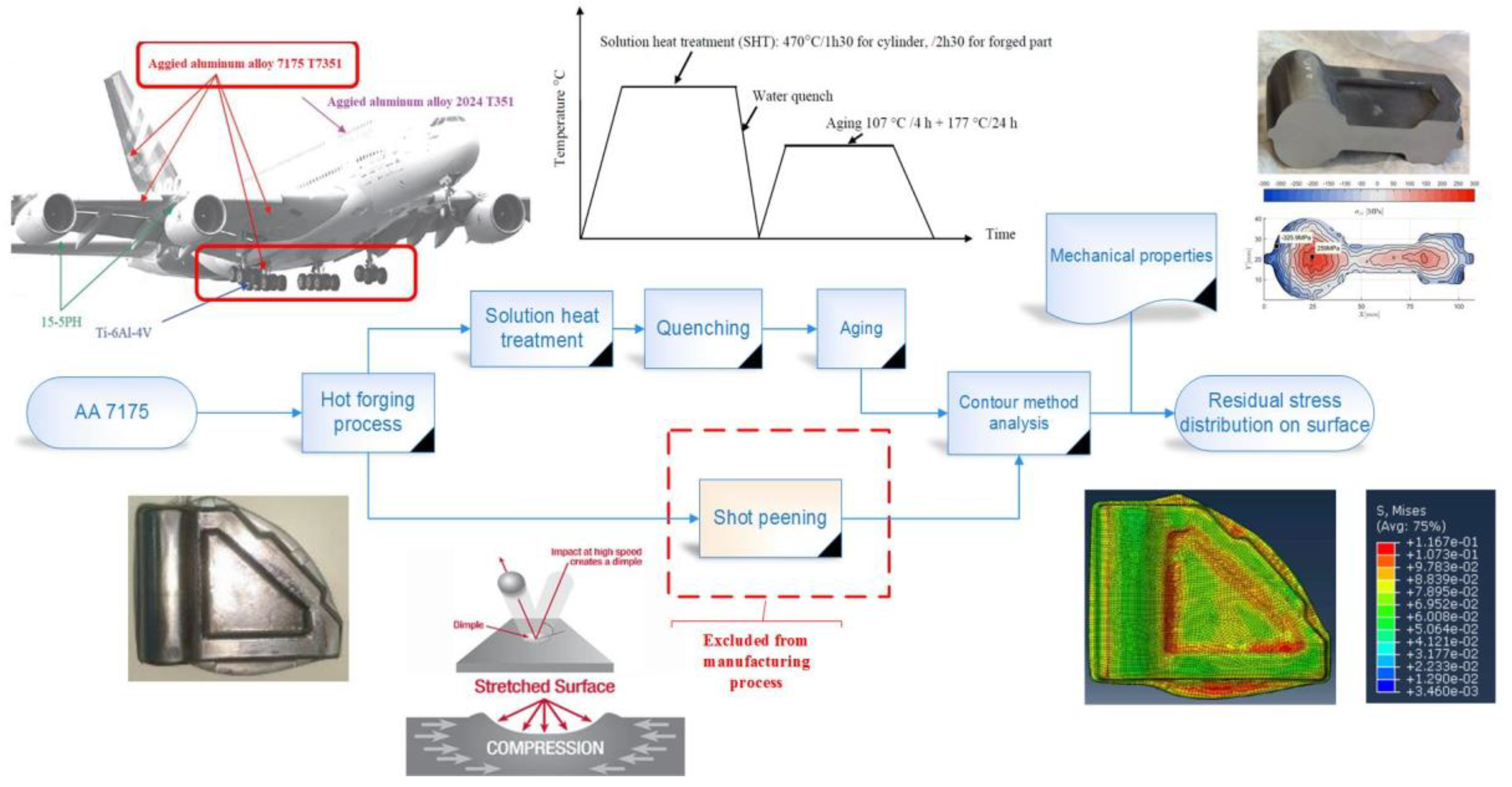
The manufacturing of sensitive and complex parts requires process planning to design a series of consecutive processes that guarantee the desired properties in the final part. The choice of these processes depends on various factors, such as selected mechanical and dimensional final properties of the part or financial considerations. However, sometimes, establishing some complementary processes is necessary to reduce manufacturing processes’ side effects, which inevitably increase manufacturing costs. Hence, the process plan could be optimized depending on the final desired properties and financial considerations. The methodology is designed to modify the manufacturing process to provide an opportunity to omit the shot-peening process, as depicted in
Figure 1. As shown in the figure, a costly shot-peening process is replaced by common heat treatment processes at a lower cost. As part of this work, an investigation has been conducted into the various aspects of the material, process, and numerical modeling techniques. This work has enabled us to better understand the behavior of aluminum alloy 7175 under our forging conditions by examining its mechanical and metallurgical properties under various conditions.
Regarding numerical simulation, a Johnson–Cook constitutive model has been characterized and used for simulations of various processes. An investigation of the integration of the effect of microstructure in material behavior laws was conducted. Accordingly, this study led to the consideration of a modified Johnson–Cook model that takes into account the effects of dynamic recrystallization during material flow. Simulations involving high strain levels produced significantly higher accuracy than those using the standard Johnson–Cook model. Additionally, an investigation was conducted regarding simulations. Here, by using the finite element method (FEM), a comparison study of the CEL (coupling Eulerian–Lagrangian) formulation and the SPH (smoothed particle hydrodynamics) formulation enabled the classification of different methods on the basis of their performance when simulating complex forged components involving large displacements (important material flow). It was necessary to develop a thermomechanical VUMAT (user’s material) subroutine in Abaqus in order to apply the SPH formulation in Abaqus to simulate coupled thermomechanical problems. An SPH method contribution was made in order to provide a more accurate simulation of the forging process. In order to accomplish this, Abaqus VUEL (user’s element) subroutines, based on the total Lagrangian formulation of solid mechanics equations, were developed.
In order to validate the results, both numerical and experimental investigations were conducted. In regard to numerical simulations, the in-house code was validated by comparing it with the commercial code of Abaqus FE. To achieve the main objective of integrating material and process modeling for product design, a suitable methodology was developed. This methodology was validated experimentally by designing and manufacturing a representative prototype of an industrial part with the closed-die hot-forging process. Moreover, microstructural investigations were also performed to gain a better grasp of the part’s properties obtained by the modified manufacturing process. This study focused on the process of hot forging in closed dies. Forging is required for aerospace applications to achieve high performance. As a result, many applications of this technology can be found in manufacturing aircraft, helicopters, and spacecraft. Forged parts are used in these machines’ engines, landing gear, and braking systems. Due to the importance of weight in all these applications, aluminum and titanium alloys are commonly used. The material of interest here is 7175 aluminum alloy, which offers high strength and corrosion resistance. This alloy has a variety of applications in aircraft, as shown in
Figure 1.
Contour Method
The contour method measures residual stresses in a 2D plane through a specimen based on solid mechanics principles. The technique consists of three main steps. The first step involves using wire-EDM to cut a free surface within the sample containing residual stresses. The wire-EDM cuts made in the material can be assumed to be perfectly flat. The second step of the technique involves measuring the surface contours on the cut section created by the slight distortions. These are typically measured using coordinate-measuring machines (CMM) with either a touch trigger probe or a laser measurement system. The third step is conducting data analysis in order to convert a three-dimensional surface contour into a two-dimensional stress field, namely the filtering of the raw data array. Finally, the measured displacement data are used to compute residual stresses through an analysis involving a specimen’s finite element (FE) model.
4. Results and Discussion
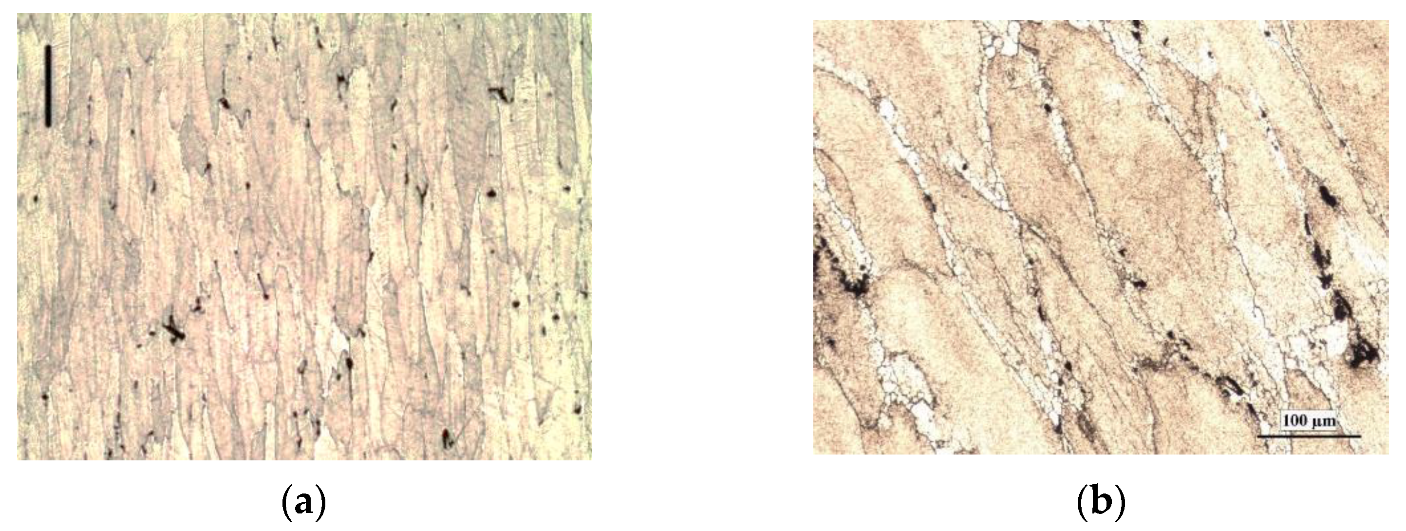
This section presents microstructural analysis by optical microscopy and stress analysis by contour method. The microstructural modifications and phase changes during the heat treatment process can affect the part’s mechanical properties and RS distribution. The optical microscopy of the material state, before and after forging and heat treatment, are shown in
Figure 2a,b, respectively.
Figure 2b demonstrates a necklace structure along the grain boundaries resulting from dynamic recrystallization.
For zones where the deformation was not very significant (18 to 36%), the grains maintained a shape similar to the initial microstructure as a function of the deformation. In contrast, in zones of high deformation, the grains were very elongated and fine (
Figure 2). In terms of dynamic recrystallization, the strain–time curves indicated that the strain at which dynamic recrystallization was confirmed for low deformation zones was reached earlier than for high deformation zones, even though it is not visible in the micrographs in high deformation cases. This confirms that recrystallization took place in these zones.
The results presented in
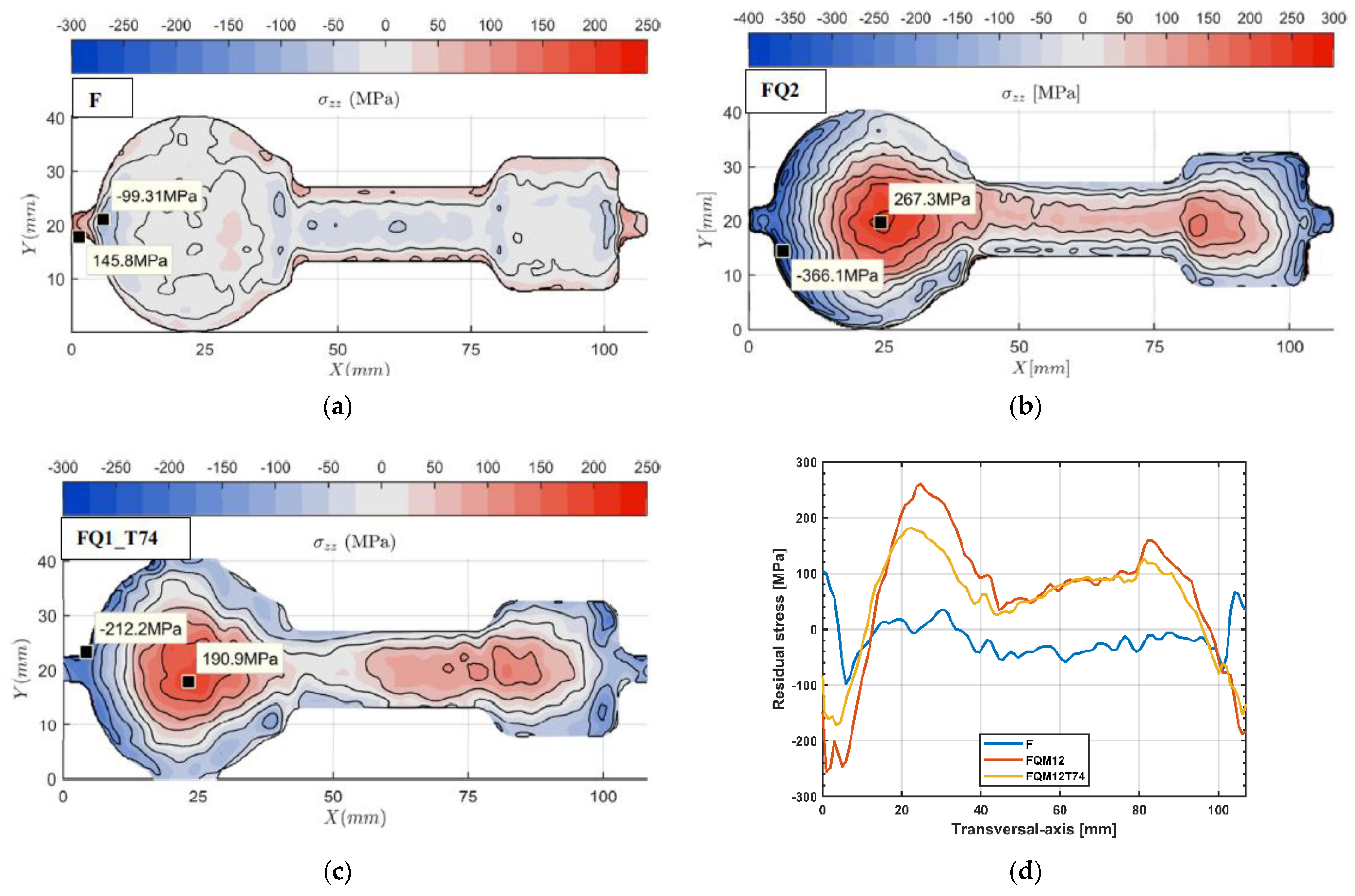
Figure 3 are the RS measurements after heat treatment on the samples.
Figure 3a shows the resulting RS (
σzz) just after the forging process with no heat treatment.
Figure 3b shows the resulting RS after quenching, and
Figure 3c represents the resulting RS after T74 aging. It can be observed that the RS on the part’s surface was tensile after forging; however, it changed to compression after quenching and after T74 aging. It is especially important that a compression RS on the surface increases fatigue strength. It is worth mentioning that the maximum RSs in compression varied from 99 MPa after hot forging to 366 MPa after quenching and to 212 MPa after T74 aging. The tensile stress varied from 145.8 MPa after forging to 267 MPa after quenching and to 191 MPa after T74 aging. As depicted in
Figure 3d, quenching and T74 aging resulted in a tensile RS in the internal section of the part. By comparing experimental results across different sections of the part (horizontal and vertical), the average standard deviation between the two experimental measurements is 12.25 MPa for the central axis of the part, and 8.26 MPa, 11.6 MPa, and 13.6 MPa for the vertical sections located at different points in the component. Therefore, an average deviation of 11–12 MPa is acceptable for future simulation results.
Additionally, it should be emphasized that the numerical models did not accurately reproduce the residual stresses at the level of the central (thin) portion of the part (
Figure 3). This may be due to the inability of numerical models to capture the effects of metallurgical transformations that may have occurred during the cooling of the part. This occurs mainly at the level of the thin section. Due to the nature of the contouring method, the stresses at the ends may result from an edge effect. (The stresses swing between tension and compression.) As a result of cutting on a part with edges, there is a possibility that some distortions will occur at the beginning and at the end of the cut (here, at the edges of the part). Based on observations made in the literature, we attempted to draw more precise conclusions regarding this topic in the following section on the residual stresses of hardening. Additionally, the burrs (“flashes”) located at the ends of the part have not been reproduced accurately. Probably, the reason for this is that the burrs in the simulation are less extensive, which may be, in part, due to the constant friction coefficient used throughout the simulation. As the shaping continues and the material undergoes changes, the nature of the contact between the dies and the part changes. Therefore, the use of a constant friction coefficient in time and space is not a complete reproduction of reality. It would be more appropriate to use a model of friction that varies during simulation. This model would take into account the state of the material in order to adjust the friction coefficient value. For a more complete and accurate process modeling, it is essential to integrate process and material parameters. Nevertheless, we did not explore this further in the present work.
Overall, applying our proposed heat treatment produces mainly compressive RSs on the surface and tensile RSs in the internal section of a hot-forged part. Having surface compressive stresses introduced by quenching and T74 aging is advantageous in increasing the endurance limit of the material and in blocking cracks. Fatigue ruptures commonly occur due to surface-crack propagation stimulated by tensile stresses at the tip of a crack. In addition, compressive stresses tend to close the crack and slow down its progression. Employing our proposed heat treatment and aging approach, the tensile surface RS of a forged part converts to a compressive stress on surface layers. In general, precipitation hardening and compressive RS formation enhanced the mechanical properties of the parts.


 ,
, 


