Abstract
As has been pointed out recently, a possible solution strategy to the wear–fatigue dilemma in fretting, operating on the level of contact mechanics and profile geometries, can be the introduction of “soft” sharp edges to the contact profiles, for example, by truncating an originally smooth profile. In that regard, analysis of possible mechanical failure of a structure, due to the contact interaction, requires the knowledge of the full subsurface stress state resulting from the contact loading. In the present manuscript, a closed-form exact solution for the subsurface stress state is given for the frictional contact of elastically similar truncated cylinders or wedges, within the framework of the half-plane approximation and a local-global Amontons–Coulomb friction law. Moreover, a fast and robust semi-analytical method, based on the appropriate superposition of solutions for parabolic contact, is proposed for the determination of the subsurface stress fields in frictional plane contacts with more complex profile geometries, and compared with the exact solution. Based on the analytical solution, periodic tangential loading of a truncated cylinder is considered in detail, and important scalar characteristics of the stress state, like the von-Mises equivalent stress, maximum shear stress, and the largest principal stress, are determined. Positive (i.e., tensile) principal stresses only exist in the vicinity of the contact edge, away from the pressure singularity at the edge of the profile, and away from the maxima of the von-Mises equivalent stress, or the maximum shear stress. Therefore, the fretting contact should not be prone to fatigue crack initiation.
1. Introduction
The components of engineering structures, which are subject to the highest stresses and which are therefore most prone to mechanical failure (in terms of yield or cracking), often are the mechanical contacts between different parts of the structure. While the solution of a given contact mechanical problem—may it be in a closed analytical form [1] or based on the Boundary Element Method (BEM) [2]—is in many cases only concerned with the stresses in the contact interface, an analysis of possible mechanical failure requires the knowledge about the stress state due to the contact loading in the whole subsurface material.
For elastic bodies obeying the restrictions of the half-space approximation, the subsurface stress state can, in theory, be determined from the contact tractions via superposition of the respective fundamental solutions for point loading by Boussinesq [3] and Cerruti [4] or via methods of potential theory [5]. However, for general contact problems, both procedures are mathematically and numerically quite cumbersome, and plane contact problems allow for a straight-forward determination of subsurface stresses based on the complex stress potential by Muskhelishvili [6]. Several comprehensive analytical solutions for elastically decoupled single plane contacts have been derived with this method, most notably for the contact with a rounded flat punch, which has been analyzed in a series of publications by various authors [7,8,9] due to its importance in the context of fretting fatigue [10] (“fretting” is the damaging of contact interfaces by small-amplitude oscillations).
In fretting, there are often two competing damage phenomena, depending on the fretting regime [11], fatigue, and wear: in the partial slip regime, the nucleation and propagation of fatigue cracks in the vicinity of the contact is the dominating damage mechanism, while, in the sliding regime, the dominant phenomenon seems to be wear [11]. This leads to the dilemma that inhibiting one of the two phenomena often facilitates the other one. For example, it is long-known that fretting wear can be hindered by introducing sharp edges in the contact profiles to suppress local slipping of the contacting surfaces. However, if the sharp edge constitutes the contact boundary, the resulting oscillating stress singularity will result in fatigue. A possible solution strategy for this dilemma on the level of the profile geometry was recently suggested by the author [12]: If the sharp edge is “soft” enough, so that contact is still established behind the edge—e.g., by truncating an originally smooth profile, like a cylinder—it can be possible to avoid (positive) tensile stresses in the vicinity of the weak stress singularity at the sharp edge, and thus avoid the formation of fatigue cracks.
On the other hand, although the truncated cylinder and truncated wedge are standard profile geometries in plane contact mechanics, exact closed-form solutions for the corresponding subsurface stress fields are still missing in the literature. Hence, these shall be provided in the present manuscript, and applied to a very simple fretting contact problem. Moreover, a numerically extremely fast and very robust semi-analytical method is proposed for the determination of the subsurface stress fields in plane contacts with more complex profile geometries, which defy an exact, closed-form solution, and compared with the analytical solution for the truncated geometries of interest.
The remaining parts of the manuscript are structured as follows: first, the research problem of interest will be stated rigorously. After that, the complex Muskhelishvili potential (which provides the subsurface stresses via elementary linear filtering of its real and imaginary parts) will be calculated in closed form for normal loading—based on the appropriate superposition of flat punch solutions, as first suggested by Jäger [13]—and for tangential loading—based on the reduction of the tangential contact problem to the respective normal contact via the principle of Jäger [14] and Ciavarella [15]. In the last section of the methodological part of the manuscript, an alternative procedure for the determination of the subsurface stress field via the direct superposition of stress fields for the flat punch and parabolic contact, thus avoiding the statement of any complex potentials, is laid out and proven numerically to give exactly the same results as the potential solution. After that, as a numerical example, periodic tangential loading of a truncated cylinder is considered in detail and some conclusive remarks finish the manuscript.
2. Problem Formulation
Let us examine the single contact of two infinite-length truncated bodies made of linearly elastic, isotropic, and homogeneous materials, with Young’s moduli , and Poisson’s ratios , , under plane strain conditions. The normal axis to the contact plane shall be y, the tangential axis x, and the lateral axis z, i.e., for the strains , . As always, the plane stress solution can be retrieved from the plane strain solution via the substitutions
where the hat denotes the respective material constants for the plane stress problem.
The contacting bodies shall obey the restrictions of the half-plane approximation, i.e., their surface gradients in the vicinity of the contact and the characteristic contact width compared to the macroscopic dimensions of the bodies are supposed to be small. The bodies’ materials are assumed to be elastically similar, so that the normal and tangential contact problems are elastically decoupled, i.e., Dundur’s second constant [16],
with the effective Young’s modulus
shall be zero. In the contact, there shall be friction according to a local Amontons–Coulomb law with a constant coefficient of friction . Effects of adhesion or surface tension are neglected. The contact is subject to a normal line load P and an in-plane tangential line load Q. The form of the gap between the two contacting surfaces , in the moment of first contact constitutes the profile function f,
Within the framework of these assumptions, the contact is equivalent to the one between a rigid indentor with the profile and an elastic half-plane with the effective Young’s modulus . As profile functions, let us consider the truncated shallow wedge,
with the small inclination angle , the half-width of the flat end face b, and Heaviside’s step function , as well as the truncated cylinder,
with the radius R of the cylinder. Note that the profile function for the truncated cylinder can be written as a superposition of the function for a flat punch with rounded corners,
where R denotes the radius of curvature for the rounded corners, with an appropriate truncated wedge profile,
A sketch of the considered contact problems is shown in Figure 1.
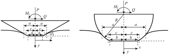
Figure 1.
Tangential contact with an elastic half-plane for a rigid truncated shallow wedge (left) and a rigid truncated cylinder (right); a is the half-width of the contact, c is the half-width of the stick zone.
We aim to determine explicit analytic expressions for the subsurface stress field under normal and tangential loading.
3. Normal Contact Loading
In this section, the stress fields arising from the pure normal loading P are derived—first, the contact solution—including the stress potential function—and, after that, the resulting stress fields are given.
3.1. Normal Contact Solution
Within the framework of the assumptions stated above, the general solution for the normal line load P as a function of the contact half-width a is given by [5]
where the prime denotes the derivative with respect to the given function argument. Hence, for the truncated shallow wedge [17],
and the truncated cylinder,
The standard procedure to determine the subsurface stress field in plane contact problems is via Muskhelishvili’s complex potential , which for pure normal loading reads [6]
with the contact pressure distribution . If the pressure distribution is known, the potential can be determined by brute-force evaluation of that complex-valued singular integral, or by an appropriate Chebyshev expansion of the pressure distribution [18]. A yet more elegant way to calculate the potential stems from Jäger [13]: As the normal contact can be thought of as the result of a series of incremental indentations by rigid flat punches with increasing half-widths and infinitesimal line loads , due to the linearity of all governing equations, the final potential will be given by an appropriate superposition of the potential for a rigid flat punch with half-width a [6],
i.e.,
Hence, with some algebra, we obtain for the truncated shallow wedge,
which for , of course, simplifies to the known result for the perfect shallow wedge [19].
To determine the potential for the truncated cylinder, we facilitate the profile superposition in Equation (8), and the fact that the potential for the rounded punch is known to be [9]
Hence, for the truncated cylinder,
which, for , of course, simplifies to the known result for the plane Hertzian contact problem [6],
Note that the given potentials are strictly correct only for . The stress fields for can, however, be determined easily from symmetry considerations (see below).
3.2. Stress Fields from Normal Loading
Once Muskhelishvili’s potential has been determined, the stress fields resulting only from the normal loading, , can be written immediately based on the standard relations [6]
where Re and Im denote the real and imaginary parts of a complex-valued quantity. Moreover, as for all plane strain elasticity problems,
As was mentioned, the given potentials are only valid for non-negative values of x. However, the stresses for can be easily calculated from simple considerations of symmetry. For symmetric normal loading (as is the case because the profiles are symmetric, and no tilting moment is applied), it is clear that normal stresses are symmetric, and shear stresses anti-symmetric in x. Hence,
4. Tangential Contact Loading
In this section, the stress fields arising only from the tangential loading Q are derived for the simplest loading history of a constant normal load and a subsequently applied increasing tangential load. Without loss of generality, we will assume that . Again, first the contact solution is detailed, and after that, the resulting stress fields are given. As the tangential contact problem under the given assumptions can be reduced easily to the pure normal contact problem, no complicated calculations are necessary.
4.1. Tangential Contact Solution
Under tangential loading and within the framework of the assumptions stated in the second section, the contact area will generally consist of an inner area of stick, , and an outer region of local slip, . For the simplest loading history described above, the contact solution immediately follows from the principle of Jäger [14] and Ciavarella [15]. The relation between the half-width c of the stick zone and the tangential line load Q is given by
and the shear tractions are
In the latter two equations, on the right-hand side, the parameter c corresponds to a fictional normal contact problem with the contact half-width c.
Accordingly, Muskhelishvili’s potential for the tangential loading [6],
can be reduced to the respective potential for the normal loading,
4.2. Stress Fields from Tangential Loading
Again, once Muskhelishvili’s potential has been determined, the stress fields resulting only from the tangential loading, , can be written immediately based on the standard relations [6]
As was mentioned, the given potentials are only valid for non-negative values of x. However, the stresses for can be easily calculated from simple considerations of symmetry. For pure tangential loading (i.e., without tilting), it is clear that normal stresses are anti-symmetric, and shear stresses symmetric in x. Hence,
5. Direct Superposition of Stress Fields for Flat Punch and Parabolic Contact
While for closed-form analytical calculations (if they are possible), the flat punch superposition of Muskhelishvili’s potential, as expressed in Equation (14), is obviously perfectly suited, its numerical evaluation for profiles that do not allow for a closed-form solution can be slightly problematic due to the complex-valued nature of the superposition integral. In these cases, a direct superposition of the stress fields under a rigid flat punch with normal and tangential loading is preferable. This procedure has already been applied successfully to axisymmetric contact problems [20] and will be laid out briefly below for plane tangential contact problems under the usual assumptions.
5.1. Normal Loading
The idea that the incomplete normal contact with a general symmetric plane profile can be understood as the result of a series of incremental flat punch indentations with increasing half-width , obviously also applies to the components of the stress tensor. Therefore, we can immediately write
with the respective relation given in Equation (9). Explicit expressions for the stress field under the flat punch are given in the Appendix A.
Now, as is known, the stress field for the indentation by a rigid flat punch is singular at the contact edges, which might pose some difficulties in the numerical evaluation of the above integral. For an even more robust formulation, we can notice that the contact pressure distributions in plane flat punch and parabolic contacts satisfy
where the index “FP” denotes the solution for a flat punch and the index “H” the parabolic (Hertzian) case. Due to linearity, the same rule applies to all stress components. Hence, introducing the substitutions
we write
which, after partial integration, results in
Thus, the determination of the stress field due to normal loading has been reduced to a simple superposition of stress fields for parabolic contacts under normal loading. Explicit expressions for the latter are given in Appendix A.
5.2. Tangential Loading
The same idea can be used to tackle the stress field arising from tangential loading, which can be thought of as the result of a series of incremental tangential loadings of flat punches with increasing half-width . Hence,
Now, what is the tangential loading procedure ? If we speak about the simplest loading history of a constant normal load and a subsequently applied increasing tangential load, is the contact half-width not constant during the tangential loading? Yes, but is meant in the “flat punch picture”; consider the following loading procedure: Flat punches with increasing half-width are pressed into the elastic half-plane according to the relation up to a contact half-width ; after that, any incremental flat punch normal loading is accompanied by an incremental flat punch tangential loading until the final contact half-width is reached. The resulting contact configuration will satisfy the Ciavarella–Jäger principle in the form of Equations (22) and (23), that is to say, it produces the correct contact configuration for the simplest loading history of a constant normal load and a subsequently applied increasing tangential load. Hence,
with the usual relation (9) for the normal load. Alternatively, completely analogous to the previous subsection, we can write the stresses as a superposition of stresses due to the tangential load under a sliding parabolic contact,
Explicit expressions for the subsurface stress fields due to the tangential loading of flat punch or sliding parabolic contacts are given in the Appendix A.
Figure 2 shows a comparison between the fully analytical solution based on the Muskhelishvili potential and a solution based on the superposition of parabolic contacts, where the integrals in Equations (32) and (35) are evaluated with the trapezoidal rule, for the contour line diagram of the equivalent von-Mises stress, normalized for the average contact pressure , in the tangential contact with a truncated cylinder, as a function of and , for , , and . As aspected, there are no notable differences between both solutions.
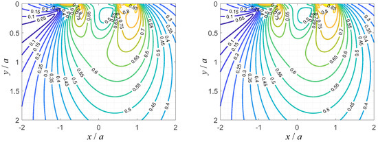
Figure 2.
Contour line diagram of the equivalent von-Mises stress, normalized for the average contact pressure , in the tangential contact with a truncated cylinder, as a function of and , for , , and ; fully analytic solution based on the complex Muskhelishvili potential (left) and solution via the numerical superposition of stress fields in the plane Hertzian contact (right).
Figure 3 shows the corresponding distributions of the largest principal stress and maximum shear stress. One distinguishes the region of positive largest principle stress at the trailing contact edge, and large negative values of largest principal stress at the edges of the flat face of the truncated cylinder. The maximum shear stress distribution highly correlates with the von-Mises equivalent stress distribution shown in Figure 2.
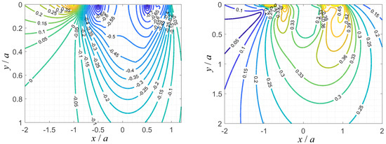
Figure 3.
Contour line diagram of the largest principal stress, normalized for the average contact pressure (left), and the maximum shear stress, normalized for the average contact pressure (right), in the tangential contact with a truncated cylinder, as a function of and , for , , and .
6. Periodic Tangential Loading of a Truncated Cylinder
As is known, for tangential contacts, the solution to the contact problem—and therefore naturally also the subsurface stress state—generally depends on the history of the loading procedure. This is in contrast to, for example, the frictionless normal contact problem, whose solution only depends on the instantaneous contact configuration—in plane, symmetric problems expressed by either the line load P, or the contact half-width a. The tangential contact solutions presented above are, as has been stated before, only valid for the simplest loading history of a constant normal load and a subsequently applied, monotonously increasing tangential load. The shown solutions can, however, serve as a basis for the analysis of more complex loading histories, as it has been shown, how the solution for general loading histories can often be constructed by appropriately superposing these basic solutions for the simplest loading history [5,13].
To illustrate this idea, in the following, the problem of periodic tangential loading with a constant amplitude, which is relevant in fretting contacts, is considered for the truncated cylinder. The time-dependence of the tangential loading is shown schematically in Figure 4. Note that the precise temporal function (sinusoidal, “saw-tooth”, etc.) is not relevant (as long, as it is periodic) because the contact configuration during unloading or reloading only depends on the instantaneous value of Q and its maximum value, i.e., the amplitude. The normal load is supposed to be constant.
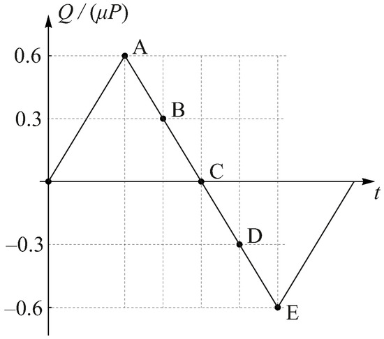
Figure 4.
Scheme of the tangential loading history for the exemplary calculation; A, B, C, D and E denote instants of the loading protocol, for which the stress state will be evaluated.
For the determination of the subsurface stress state, we only require the general structure of the tangential contact solution for the considered type of loading. To obtain that, we will use yet another superposition idea, which was first used by Jäger [21] for the tangential contact of elastic spheres under arbitrary 2D oblique loading. Up to point A in the loading diagram, the tangential load is increasing monotonously and the tangential contact solution is therefore given by the classical Ciavarella–Jäger result in Equations (22) and (23),
where the star denotes that this is the basic solution for the elementary loading history. Accordingly, the contributions of the tangential load to the subsurface stress state are given by Equation (27) or (35).
Then, the sign of the change in Q is reversed. At the “reversal point” A, there is a spontaneous state of complete sticking of the contact area, since every point of the sliding area is—according to the law of friction—in the “limit state” of sticking, . After that, a new slip area propagates from the edge of the contact. Since in the slip area the direction of the frictional stresses has been reversed, but their value is still determined by the law of friction, a simple Ciavarella–Jäger solution can be linearly superposed. The distribution of the frictional stresses on the “path” from A to E is therefore due to the Ciavarella–Jäger principle given by
where the minimum half-width of the stick area, , follows from the maximum tangential load,
and the current value of the half-width of the stick area, c, can be determined from the superposition relation for the tangential load,
Due to the linearity of all governing equations, the same superposition can be applied for the determination of the tangential loading contributions to the subsurface stress state, based on the basic solutions given in Equation (27) or (35).
During reloading, i.e., after point E in the loading diagram, the same happens with the tangential loading directions reversed. Hence, the superpositions in Equations (37) and (39) can be used, with all signs reversed on the right-hand side of the equations.
If all stresses are normalized for the average contact pressure , the resulting non-dimensional stresses will only depend on the non-dimensional half-width of the flat face , the friction coefficient , the loading ratio , and the Poisson ratio .
Figure 5 shows the distribution of the equivalent von-Mises stress in the loading plane in normalized variables, for , , and , at the points A, B, C, and D of the loading diagram; the respective plot in the point E will be just the plot for the point A with the direction of the x-axis reversed, and is therefore not shown.
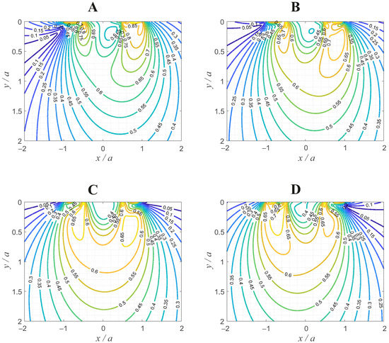
Figure 5.
Contour line diagram of the equivalent von-Mises stress, normalized for the average contact pressure , in the oscillating tangential contact with a truncated cylinder, as a function of and , for , , and ; for the points (A), (B), (C), and (D) of the loading diagram in Figure 4 (each subfigure corresponds to the respective point in the loading diagram).
In Figure 6 and Figure 7, the corresponding subsurface distributions of the maximum shear stress and largest principal stress in the loading plane are shown in normalized variables, at the points A, B, C, and D of the loading diagram. The maximum shear stress distributions correlate well with the ones for the von-Mises equivalent stress given in Figure 5; as expected, positive (i.e., tensile) principal stresses only exist in the vicinity of the contact edge, away from the pressure singularity at the edge of the profile, and away from the maxima of the von-Mises equivalent stress, or the maximum shear stress. Therefore, the fretting contact should not be prone to fatigue crack initiation.
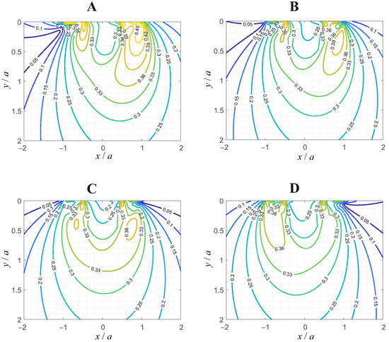
Figure 6.
Contour line diagram of the maximum shear stress, normalized for the average contact pressure , in the oscillating tangential contact with a truncated cylinder, as a function of and , for , , and ; for the points (A), (B), (C), and (D) of the loading diagram in Figure 4 (each subfigure corresponds to the respective point in the loading diagram).
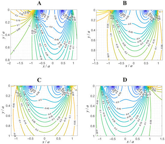
Figure 7.
Contour line diagram of the largest principal stress, normalized for the average contact pressure , in the oscillating tangential contact with a truncated cylinder, as a function of and , for , , and ; for the points (A), (B), (C), and (D) of the loading diagram in Figure 4 (each subfigure corresponds to the respective point in the loading diagram).
7. Discussion
Analytic solutions for the subsurface stress fields in tangential contacts of elastically similar truncated wedges and cylinders have been provided. Two solution methods have been utilized: the determination of Muskhelishvili’s complex stress potential and the direct superposition of stress fields under a rigid flat punch or in the plane Hertzian contact. Both methods have been proven numerically to give exactly the same results (they are, in fact, mathematically equivalent for the contact problems studied in the present manuscript). The determination of the subsurface stress state via an appropriate superposition of the respective known exact solutions for parabolic contact is an extremely fast, easily implemented, and very robust method, which can also be used for more complicated profile geometries, for example arising from the effects of wear.
While Muskhelishvili’s potential corresponds to a specific integral equation, and therefore to a specific class of problems (namely, plane contacts of homogeneous materials), the superposition of incremental flat punch contacts (or parabolic contacts, if one wishes to avoid the edge singularity of the flat punch problem) is a more general idea, whose applicability has been discussed before [20].
As for most analytical contact solutions, the underlying assumptions may pose more or less severe restrictions that have to be kept in mind when applying the obtained results to real engineering contacts. In the present case, the severest limitations stem from the assumptions of linear elasticity and of a local Amontons–Coulomb friction law with a constant coefficient of friction. In real engineering contacts, the contacting materials, depending on their “class”, will exhibit different degrees of, e.g., viscoelasticity, hyperelasticity, or plasticity. In addition, the Amontons law is, of course, a rather blunt simplification of frictional interaction. Both of these shortcomings of the present study could be tackled in future work without severe methodological alterations, if the problem retains constitutive linearity, e.g., incorporating linear viscoelasticity [22] or slip-weakening laws [23].
On the other hand, the advantage of analytic solutions lies in their exactness; they are not bound to discretization or other numerical approximations, and can thus serve as benchmark solutions for numerical solvers—e.g., based on the Finite-Elements (FE) or Boundary Elements Methods—which, in turn, are far more flexible with respect to the physical modelling.
In that regard, one should also note that recently very powerful numerical methods have been developed for the determination of subsurface stress fields in complex two- and three-dimensional problems, namely the differential quadrature finite element method—which proved to require significantly less degrees of freedom than a “regular” FE-based model in the simulation of free vibrations of laminated beams and plates [24]—and the 2D Bézier method, which is able to solve two-dimensional problems for arbitrary complexity of geometry [25].
In addition, note that, for elastically dissimilar bodies, there is elastic coupling between the normal and tangential contact problems, i.e., the presence of tangential tractions alters the normal contact problem, and vice versa. This severely complicates the rigorous problem treatment; in fact, closed-form analytical contact solutions for dissimilar materials are only possible for few special cases. Correspondingly, the manuscript’s analysis is only valid for similar materials.
The concept of introducing “soft” sharp edges to avoid wear and fatigue is similar to the already widely used idea of using rounded flat punches in fretting: the flat face shall reduce local slipping and thus wear, and the rounded corners aspire to soften the stress singularity at the edge of the punch. However, a detailed contact mechanical comparison of both types of profile geometries in fretting configurations still remains for future work.
Finally, in the future, the fretting behaviour of truncated contact profiles shall be investigated experimentally, with respect to energy dissipation, wear, and fatigue.
Funding
We acknowledge support by the Open Access Publication Fund of TU Berlin. This research was funded by the German Research Foundation under the project number PO 810/66-1.
Institutional Review Board Statement
Not applicable.
Informed Consent Statement
Not applicable.
Data Availability Statement
Not applicable.
Conflicts of Interest
The author declares no conflict of interest.
Appendix A. Stress Fields from the Plane Flat Punch and Parabolic Contact
Inserting the flat punch potential from Equation (13) into Equation (19) gives the stress field due to normal loading of a rigid flat punch with half-width a,
with A and (here and in the following) being the absolute value and complex argument of
Note that, for and , the complex argument, which has to be used, is ; for und , the standard application of Equation (A2) will readily give the correct argument .
Inserting the potential for the plane Hertzian contact problem from Equation (18) into Equation (19) gives the stress field under a plane Hertzian contact with the radius of curvature R, as a function of the contact half-width a,
Inserting the flat punch potential into Equation (27) (c must be zero because there are no partial slip configurations in the flat punch contact) gives the stress field due to tangential loading of a rigid flat punch,
Inserting the potential for the plane Hertzian contact into Equation (27) and setting gives the stress field due to the tangential loading under a sliding plane Hertzian contact,
Note that all stress fields given in this Appendix A satisfy the necessary symmetry relations; that is to say, they are valid for all values of x.
References
- Popov, V.; Heß, M.; Willert, E. Handbook of Contact Mechanics—Exact Solutions of Axisymmetric Contact Problems; Springer: Berlin, Germany, 2019. [Google Scholar] [CrossRef]
- Xu, Y.; Jackson, R. Boundary element method (BEM) applied to the rough surface contact vs. BEM in computational mechanics. Friction 2019, 7, 359–371. [Google Scholar] [CrossRef]
- Boussinesq, J. Application des Potentiels a L’etude de L’Equilibre et du Mouvement des Solides Elastiques; Imprimerie L. Danel: Lille, France, 1885. [Google Scholar]
- Cerruti, V. Ricerche intorno all’equilibrio de’ corpi elastici isotropi. Rend. Acc. Naz. Lincei 1882, 3, 81–122. [Google Scholar]
- Barber, J. Contact Mechanics; Springer International Publishing: Basel, Switzerland, 2018. [Google Scholar]
- Muskhelishvili, N. Singular Integral Equations; Translation of the Russian original of 1944; Wolters-Noordhoff Publishing: Groningen, The Netherlands, 1958. [Google Scholar]
- Schubert, G. Zur Frage der Druckverteilung unter elastisch gelagerten Tragwerken. Ing. Arch. 1942, 13, 132–147. [Google Scholar] [CrossRef]
- Ciavarella, M.; Hills, D.; Monno, G. The influence of rounded edges on indentation by a flat punch. Proc. Inst. Mech. Eng. C J. Mech. Eng. Sci. 1998, 212, 319–327. [Google Scholar] [CrossRef]
- Jäger, J. New analytical solutions for a flat rounded punch compared with FEM. In Computational Methods in Contact Mechanics V; Dominguez, J., Brebbia, C., Eds.; WIT Press: Southampton, UK, 2001; pp. 307–316. [Google Scholar]
- Ciavarella, M.; Demelio, G. A review of analytical aspects of fretting fatigue, with extension to damage parameters, and application to dovetail joints. Int. J. Solids Struct. 2001, 38, 1791–1811. [Google Scholar] [CrossRef]
- Vingsbo, O.; Söderberg, S. On Fretting Maps. Wear 1988, 126, 131–147. [Google Scholar] [CrossRef]
- Willert, E. Influence of Wear Profile Geometry on Critical Plane Fatigue Crack Initiation Criteria in Plane and Axisymmetric Elastic Fretting Contacts. Front. Mech. Eng. 2022, 8, 904282. [Google Scholar] [CrossRef]
- Jäger, J. Half-planes without coupling under contact loading. Arch. Appl. Mech. 1997, 67, 247–259. [Google Scholar] [CrossRef]
- Jäger, J. A New Principle in Contact Mechanics. J. Tribol. 1998, 120, 677–684. [Google Scholar] [CrossRef]
- Ciavarella, M. The generalized Cattaneo partial slip plane contact problem. I—Theory. Int. J. Solids Struct. 1998, 35, 2349–2362. [Google Scholar] [CrossRef]
- Dundurs, J. Discussion on “Edge-Bonded Dissimilar Orthogonal Elastic Wedges Under Normal and Shear Loading”. J. Appl. Mech. 1969, 36, 650–652. [Google Scholar] [CrossRef]
- Leng, Y.; Hu, Y.; Zheng, L. Adhesive Contact of Flat-Ended Wedges: Theory and Computer Experiments. J. Tribol. 1999, 121, 128–132. [Google Scholar] [CrossRef]
- Truman, C.; Sackfield, A.; Hills, D. Contact mechanics of wedge and cone indenters. Int. J. Mech. Sci. 1995, 37, 261–275. [Google Scholar] [CrossRef]
- Truman, C.; Sackfield, A. Closed-Form Solutions for the Stress Fields Induced by Blunt Wedge-Shaped Indenters in Elas-tic Half-Planes. J. Appl. Mech. 2001, 68, 817–819. [Google Scholar] [CrossRef]
- Willert, E.; Forsbach, F.; Popov, V. Stress tensor and gradient of hydrostatic pressure in the contact plane of axisymmetric bodies under normal and tangential loading. ZAMM Z. Ang. Math. Mech. 2020, 100, e201900223. [Google Scholar] [CrossRef]
- Jäger, J. Elastic contact of equal spheres under oblique forces. Arch. Appl. Mech. 1993, 63, 402–412. [Google Scholar] [CrossRef]
- Lee, E.; Radok, J. The Contact Problem for Viscoelastic Bodies. J. Appl. Mech. 1960, 27, 438–444. [Google Scholar] [CrossRef]
- Papangelo, A.; Ciavarella, M.; Barber, J. Fracture mechanics implications for apparent static friction coefficient in contact problems involving slip-weakening laws. Proc. R. Soc. A 2015, 471, 20150271. [Google Scholar] [CrossRef]
- Yan, Y.; Liu, B.; Xing, Y.; Carrera, E.; Pagani, A. Free vibration analysis of variable stiffness composite laminated beams and plates by novel hierarchical differential quadrature finite elements. Comp. Struct. 2021, 274, 114364. [Google Scholar] [CrossRef]
- Kabir, H.; Aghdam, M. A generalized 2D Bézier-based solution for stress analysis of notched epoxy resin plates reinforced with graphene nanoplatelets. Thin-Walled Struct. 2021, 169, 108484. [Google Scholar] [CrossRef]


Publisher’s Note: MDPI stays neutral with regard to jurisdictional claims in published maps and institutional affiliations. |
© 2022 by the author. Licensee MDPI, Basel, Switzerland. This article is an open access article distributed under the terms and conditions of the Creative Commons Attribution (CC BY) license (https://creativecommons.org/licenses/by/4.0/).