Article

Local Stability in the Process of Excavation Located in High Permeability Saturated Sand of Diaphragm Wall Construction

1
Department of Geotechnical Engineering, College of Civil Engineering, Tongji University, No. 1239 Siping Road, Yangpu District, Shanghai 200092, China
2
Shanghai Tunnel Engineering Co., Ltd., Shanghai 200032, China
3
Department of Mathematics and Physics, Institute of Photonics, Leibniz University Hannover, 30167 Hannover, Germany
*
Author to whom correspondence should be addressed.
Appl. Mech. 2022, 3(4), 1254-1269; https://doi.org/10.3390/applmech3040072
Submission received: 30 September 2022 / Revised: 19 October 2022 / Accepted: 26 October 2022 / Published: 31 October 2022
(This article belongs to the Special Issue Feature Papers in Applied Mechanics)

Abstract

:
The stability of the slurry trench is very important in the construction of the underground diaphragm wall. In the current research, the local instability of the slurry trench is mainly investigated after the excavation of a unit slot is completely completed. However, the local stability in the process of excavation has received little attention. In this paper, the local stability in the process of excavation located in high permeability strata of diaphragm wall construction is investigated. A slurry infiltration experiment was carried out to investigate the distribution of the excess pore pressure in the high permeability strata, which can determine the effective support pressure. Then, the local stability of the slurry trench in the process of excavation located in high permeability saturated sand is calculated. The results show that the same types of sand according to the design code cannot be simply treated to have the same permeability and similar distribution of the excess pore pressure, since whether the filter cake can be formed and the quality of the filter cake are the key factors to determine the distribution of the excess pore pressure. This is also crucial for the local stability in the process of excavation located in high permeability saturated sand. It is suggested that attention should be paid to the local stability in the process of excavation located in high permeability strata when the slurry infiltration mode is the pure permeable zone.

1. Introduction

Slurry trenches are widely used during the excavation of diaphragm wall construction, and a large deformation or even collapse may occur if the slurry has a poor supporting effect for the trench walls. The stability of the slurry trench can be divided into global stability and local stability [1]. Thus far, the existing research mainly focuses on the global stability of the slurry trench [2,3,4,5]. Unlike global stability, the local instability induced by the falloff of the unstable soil is invisible, making it difficult to master the mechanism of the local instability, which easily causes the occurrence of the local instability in practice.
Many local stability models of the slurry trench have been proposed. Han [6] proposed a 2D rational continuous velocity field for the local instability in pure cohesive soil. Then, An [7] analyzed the local stability of the slurry trench by the limit equilibrium method. In addition, Liu [8] adopted a new mechanism called the three-dimensional translational mechanism to analyze the local stability of the slurry trench, with the effect of seepage being accounted for in the mechanism. In these local stability models of the slurry trench, the safety factor calculated by these models has only one value; this value represents the safety factor of the local instability for the whole weak interlayer after excavation of a unit slot is completely completed. In practical engineering, the staggered-excavation method is adopted in the excavation of the diaphragm wall construction, the trench excavation is a gradual and time-dependent process, and the local instability does not only occur when the entire weak interlayer in a unit slot is completely exposed, but the local instability may also occur in the process of excavation located in the weak interlayer. However, little attention has been paid to the local stability of the slurry trench in the process of excavation located in the weak interlayer.
In the process of excavation located in the weak interlayer, the grab digs out a certain depth of soil in each excavation operation, slurry starts to infiltrate into the strata which are exposed after an excavation operation to replace the pore groundwater. Then, the excess pore pressure ahead of the excavation face increases, which lowers the effective pressure in the soil [9,10]. The effective support pressure is very important for the local stability of the slurry trench. It should be noted that this support pressure refers to the support pressure acting on the unstable body, rather than the pressure difference between the slurry and groundwater [11]. The effective support pressure should be focused on studying the local stability of the slurry trench in the process of excavation located in the weak interlayer. Different slurry infiltration phenomena appear in different strata, which results in different distributions of the excess pore pressure. Then, the distributions of the excess pore pressure greatly influence effective support pressure. Muller-Kirchenbauer [12] roughly classified the slurry infiltration phenomenon into three categories: I. If the pores in the sandy strata are too small, a dense filter cake is rapidly formed on the trench walls, and the effective support pressure grows to a high value [13]. II. If the pores are too large, the bentonite particles cannot effectively fill the pores of the sandy strata, and slurry flows through the sandy strata like clear water. III. If, between the above two strata, some bentonite particles are intercepted and deposited in pores of the sandy strata, slurry stops infiltrating when it infiltrates a certain distance. For infiltration phenomenon I, the support pressure almost acts around the excavation surface, and the probability of local instability is small. The strata corresponding to infiltration phenomenon II and III are both the high permeability strata, but for infiltration phenomenon II, the strata cannot be filled with bentonite particles, the distribution of the excess pore pressure is similar to that of pure water infiltration and the calculation of the safety factor for the local stability is simple. Thus, only the local stability of slurry infiltration phenomenon III is investigated in this study.
The aim of the present study is to investigate the local stability in the process of excavation located in high permeability saturated sand of diaphragm wall construction. To calculate the safety factor of the local stability, the effective support pressure must be obtained. In this study, a slurry infiltration experiment was carried out to obtain the distribution of excess pore pressure. Then, the effective support pressure can be obtained. In addition, Tao [14] indicated that the initial hydraulic gradient has a great influence on the infiltration characteristics of the slurry. Thus, to ensure the data obtained from the slurry infiltration experiment is more suitable for practical engineering, a numerical simulation was carried out to investigate the initial hydraulic gradient in the process of excavation before the slurry infiltration experiment. Finally, the safety factors for the local stability in the process of excavation located in high permeability were calculated.

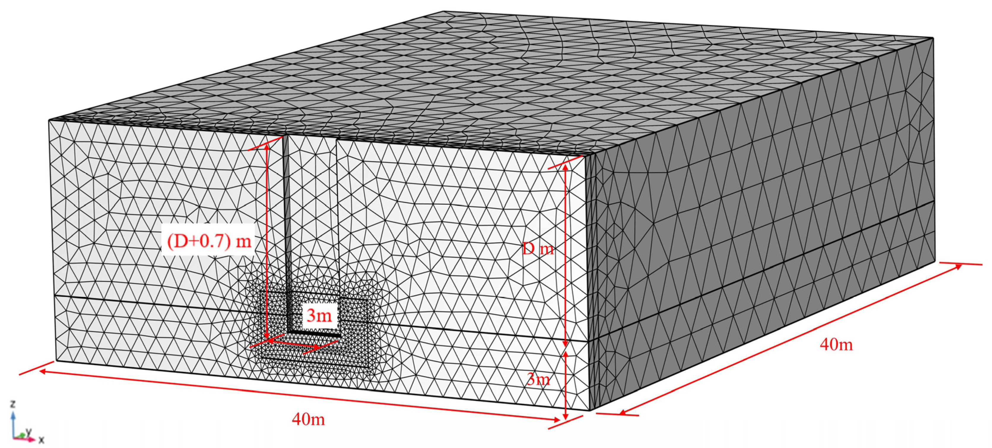
2. Numerical Analysis for the Initial Hydraulic Filed Located in Sandy Stratum

Although the initial hydraulic gradient was investigated by Tao [15], it was based on the actual working conditions of the slurry shield tunnel, and the initial hydraulic gradient adopted in the experiment was obtained from the analytical solution of the hydraulic field. The hydraulic field ahead of the excavation face develops continuously during the excavation of a diaphragm wall construction until the slurry stops infiltrating. Therefore, the initial hydraulic gradient of the slurry infiltration under the condition of a diaphragm wall should be considered based on the transient field, and the 3D finite element method based on the COMSOL platform was adopted to carry out the initial hydraulic field ahead of the excavation face. The prediction of the initial hydraulic field ahead of the excavation face is based on the basic differential equation for transient flow, written as:
( k x H x ) x + ( k y H y ) y + ( k z H z ) z = S s H t   ,  
where H is the piezometric head in the aquifer, Ss is the coefficient of specific storage, and k is the permeability coefficient. Because the compressibility of water is much smaller than that of soil, the compressibility of water is ignored, and only the elastic compression of soil is considered in this simulation.
Figure 1 presents a half numerical model of the diaphragm wall construction where 3 m thick sandy strata are covered by Dm thick clay stratum with very low permeability. The dimensions of the model are 30 m × 40 m × (D + 3) m in the transversal, longitudinal and vertical directions, respectively, which are large enough to avoid the influence of the boundary effects on the distribution of the hydraulic field. Considering the working condition of the jump-excavation method, it is approximately considered that a 3 m × 0.5 m × (D + 0.7) m cuboid located in the weak interlayer can be excavated in an excavation operation, and a piezometric head hf that increases along the depth direction is prescribed to the excavation face. Furthermore, it is assumed that the groundwater level is 2 m below the ground, the slurry surface is parallel to the ground all the time, and the bottom surface is impermeable in this simulation.
According to the infiltration model proposed by Saada [16], the bentonite–water slurry can be regarded as a mixture of the bentonite particles and water during the slurry infiltration. Sand, which is regarded as a typical porous medium, has adsorption and interception effects on the bentonite particles. In addition, the captured bentonite particles remain in the pores of the sand, which in turn affects the slurry infiltration. In this numerical simulation, in a very short time, it can be assumed that the bentonite particles cannot effectively fill the strata, and only pure water infiltrates into the strata. Thus, the hydraulic field of the pure water at 0.5 s is regarded as the initial hydraulic field.
In this numerical simulation, the thickness of clay strata D covering sandy soil is 10 m, 20 m, and 30 m. The weight of the slurry increases with the slot depth. In addition, the properties of clay strata and sandy strata of different particle sizes adopted in the simulation are listed in Table 1. Two fractions and three slot depths were chosen to simulate a real trench excavation. It resulted in six combinations (Table 2).
In Figure 2, the contour of the initial hydraulic field for the center ring of the excavation face in sandy stratum under the different conditions is represented, △H represents the hydraulic head of excess pore pressure, and i0 represents the initial hydraulic gradient, which is calculated by the initial hydraulic field. The initial hydraulic field ahead of the excavation face gradually slows down as the distance increases, and the initial hydraulic gradient for slurry infiltration is approximated by calculating the initial hydraulic field in the zone within 20 cm perpendicular to the excavation face in this simulation. Through calculation, the initial hydraulic gradient under each working condition is roughly in the range of 1.5–6, which is much smaller than that in the traditional slurry infiltration experiment. Compared with the initial hydraulic gradient calculated by Tao’s analytical solution, the initial hydraulic gradient is similar to those obtained by numerical simulation in this study. Although the initial hydraulic gradient calculated by Tao [15] is obtained based on the working condition of the slurry shield, the slurry infiltration phenomenon is similar to the trench excavation. In addition, the influence of different geological conditions and total slurry pressure on the initial hydraulic gradient can be considered in the numerical simulation. The initial hydraulic gradient increases with the increase of the pressure difference between slurry and hydrostatic water, and it decreases when the particle size of the sand becomes larger. In addition, the maximum initial hydraulic gradient in simulation No.1c is around 5.65, the minimum initial hydraulic gradient in simulation No.2a is around 1.62, and the maximum difference of initial hydraulic gradient can reach around 3.5 times. This has a great influence on the infiltration characteristics of slurry. Therefore, to obtain the experimental data closer to the actual working conditions, the corresponding initial hydraulic gradient should be adopted in the experiment.

3. Experimental Study for the Distribution of Excess Pore Pressure When the Slurry Infiltrates in the High Permeability Saturated Sand
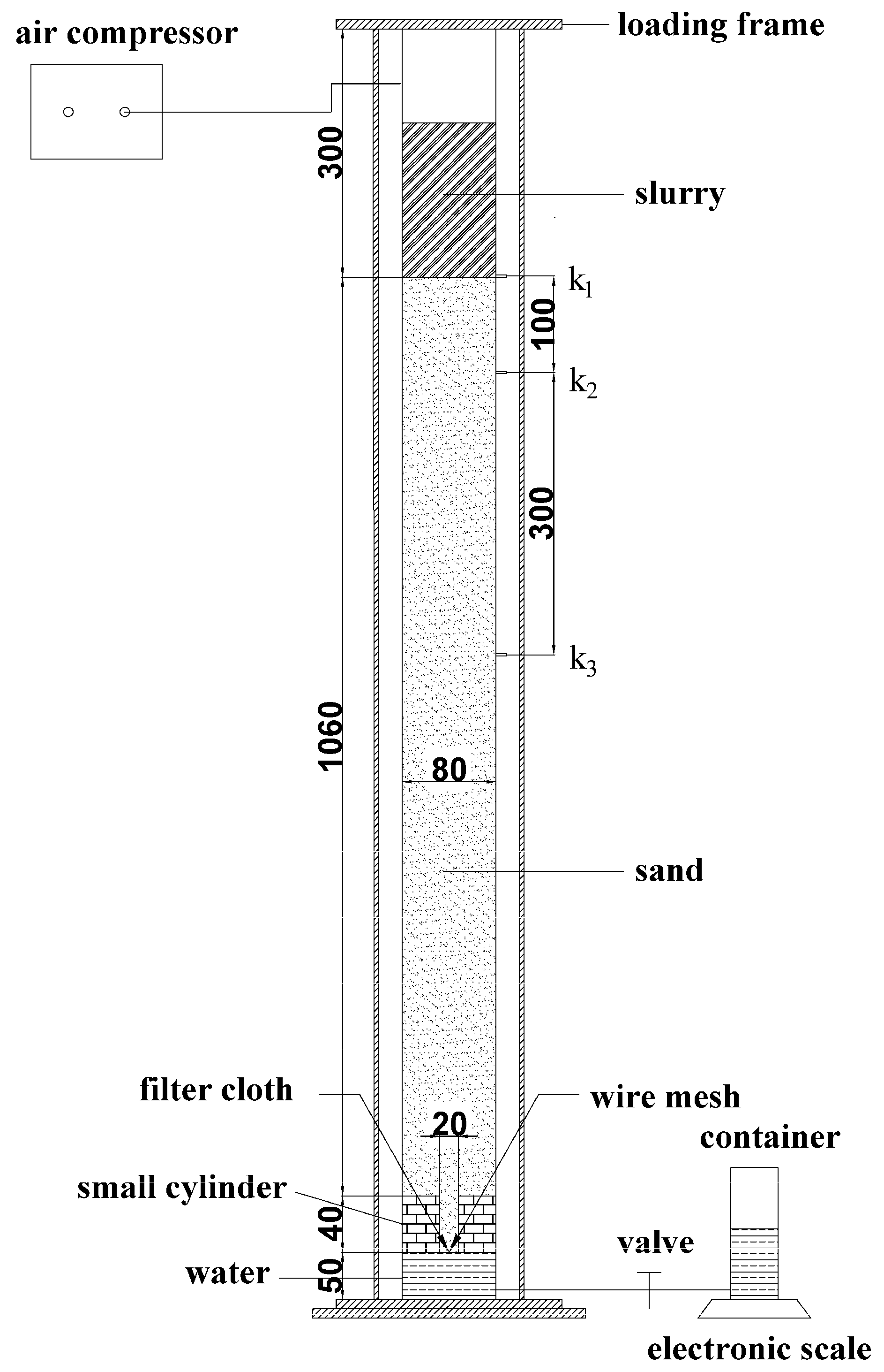
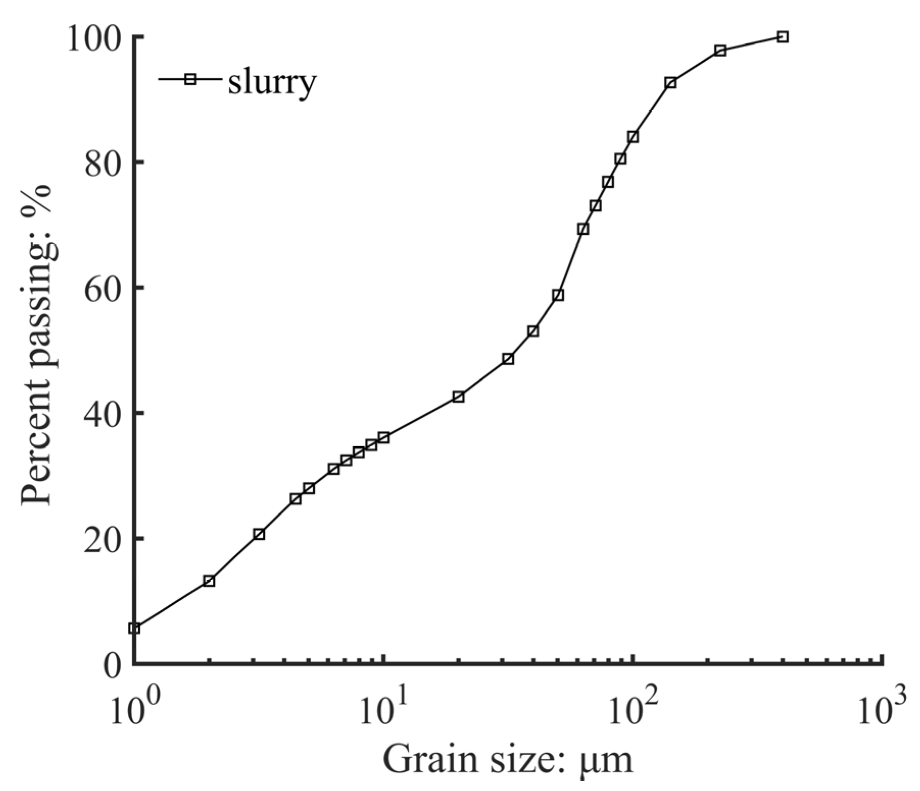
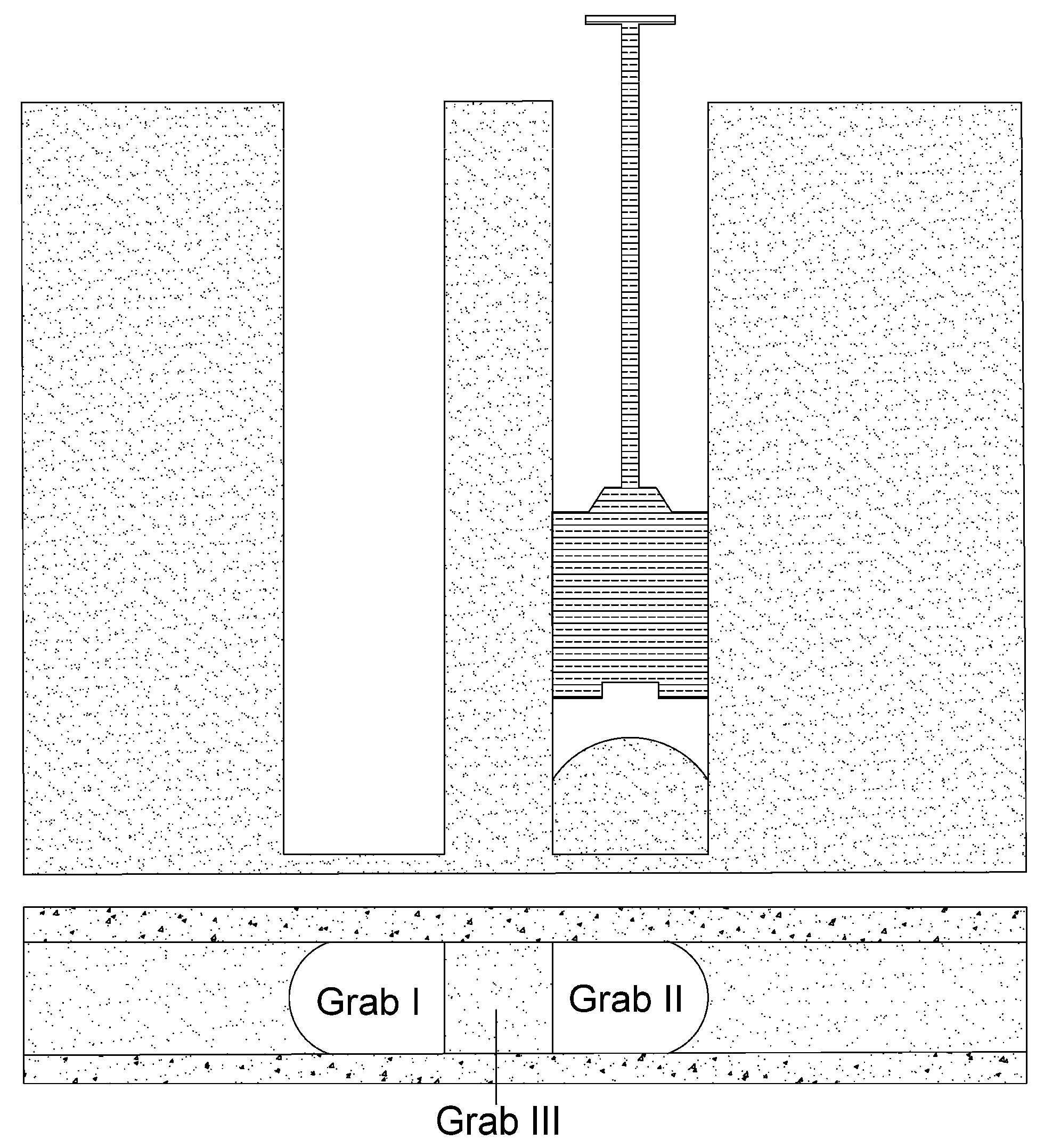
3.1. Set-Up

Based on the numerical simulation results from Chapter 2, the initial hydraulic gradient at the center of the tunnel face is different for different conditions of the trench excavation. To adopt a comparable hydraulic gradient in the laboratory test as in the field, the penetration path of the device should be set to match the corresponding initial hydraulic gradient, the initial hydraulic gradient over the sand is i0 = Δϕ/Ls (the difference in piezometric head over the sand is Δϕ, the equivalent length of the penetration path is Ls), and the particle size distribution of the experimental sand is between 0.5–1.0 mm. According to the results of the initial hydraulic gradient in Chapter 2, the equivalent length of the penetration path should be set at 1.7 m. As shown in Figure 3, referring to the set-up modified by Tao [17] in the experiment of slurry infiltration, a small poly (methyl methacrylate) (PMMA) cylinder was placed in the bottom of a large PMMA cylinder in the experiment of slurry infiltration, and the equivalent length of the penetration path is calculated based on the Equation (2), written as:
  L s = L s 1 + L s 2 ( D 1 D 2 ) 2 + D 1 2 4 D 2 D 1 4 ,  
where Ls1 and Ls2 are the heights of sand in the large cylinder and the small cylinder, respectively; D1 and D2 are the inner diameter of the large cylinder and the small cylinder, respectively. Ls is the equivalent length of a homogeneous sand column with the same flow resistance.
The amount of discharged water was measured continuously with an electronic balance, and the infiltration distance of the slurry was calculated by Equation (3) [18], written as:
e ( t ) = e m a x · V ( t ) V m a x   ,  
where e(t) = time-dependent infiltration distance (m); emax = final penetration depth (m); V(t) = time-dependent volume of discharged fluid (m3); and Vmax = final volume of the discharged fluid (m3).
The infiltration distance and the amount of discharged water observed in the experiment also verify the correctness of Equation (3). During the experiment of slurry infiltration, all data were measured with a frequency of 1 Hz. Three pore water pressure transducers (PPTs) with a pressure range of 0–100 kPa were installed in the taps on the cylinder to measure the pore water pressure in the slurry and the sand. The PPT labeled k1 was set at the slurry–sand interface to measure the slurry pressure. In addition, the PPTs labeled k2 and k3 were positioned at 10 cm and 40 cm below the slurry–sand interface, respectively.

3.2. Experimental Procedure

A new type of composite sodium-based bentonite used in Shanghai in the construction of the underground diaphragm wall is adopted, which comprises water and pure alkali as the main materials for slurry preparation. The bentonite, the water, and the pure alkali were mixed in the desired proportions for 10 mins; then, the mixture was allowed to hydrate further for 24 h in accordance with API [19], and it was mixed for 5 mins again just before use. In addition, the properties of fresh slurry are presented in Table 3. The characteristic of the slurry used in this experiment meets the European Standard EN-1538 [20]. The grain size distribution of bentonite used for the slurry is shown in Figure 4. According to Code for Investigation of Geotechnical Engineering [21], the mass of particles that is larger than 0.5 mm is more than 50% of the total mass, which is called the coarse sand and is a highly permeable stratum. In addition, because only the local stability of slurry infiltration phenomenon III, which is mentioned in the Introduction section, is investigated in this study, the particle size of the sand should not be too large. The particle size of the sand used in the experiment is between 0.5 mm–1.0 mm. The sand was compacted in the PMMA cylinders by tamping the saturated sand under water with a wire mesh covered by a filter cloth. The filter cloth on the wire mesh allowed water flow but blocked the sand grains. A relative density of approximately 90% was reached at which the porosity of the sand was 0.40.
At the start of the experiment, the slurry was pressured with a predetermined value of air pressure. The infiltration started as the valve at the bottom was opened immediately after applying pressure. When the slurry basically did not infiltrate into the strata, the valve was closed and the air pressure was released, and the discharged water and excess pore pressure were automatically recorded. Repeating the experiment, the data under different conditions were recorded separately.
The experimental program (Table 4) was designed to investigate the distribution of excess pore pressure when the slurry infiltrates into the high permeability saturated sand. Although the particle size of the sand used in the experiment is between 0.5 mm–1.0 mm, two distinct distributions of excess pore pressure field occur in the experiment. When the first distribution of the excess pore pressure occurs, it can be observed in this experiment that no filter cake formed on the slurry–sand interface. However, the slurry–sand interface is covered by the filter cake in the experiment when the second distribution of the excess pore pressure occurs. Thus, the slurry infiltration mode of the first distribution is called the “pure permeable zone”, and the slurry infiltration mode of the second distribution is called “filter cake + permeable zone” in this study. The possible reason for this is that, although the samples are in the same particle size range, the overall particle size of some samples is smaller and the overall particle size of other samples is larger. One slurry concentration, two slurry infiltration modes, and three levels of injection pressure were chosen in the experiments.

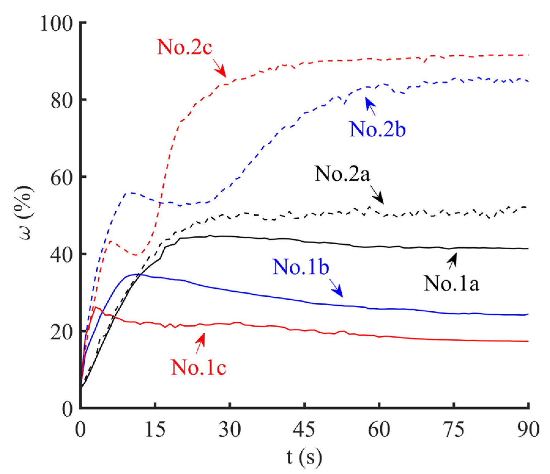
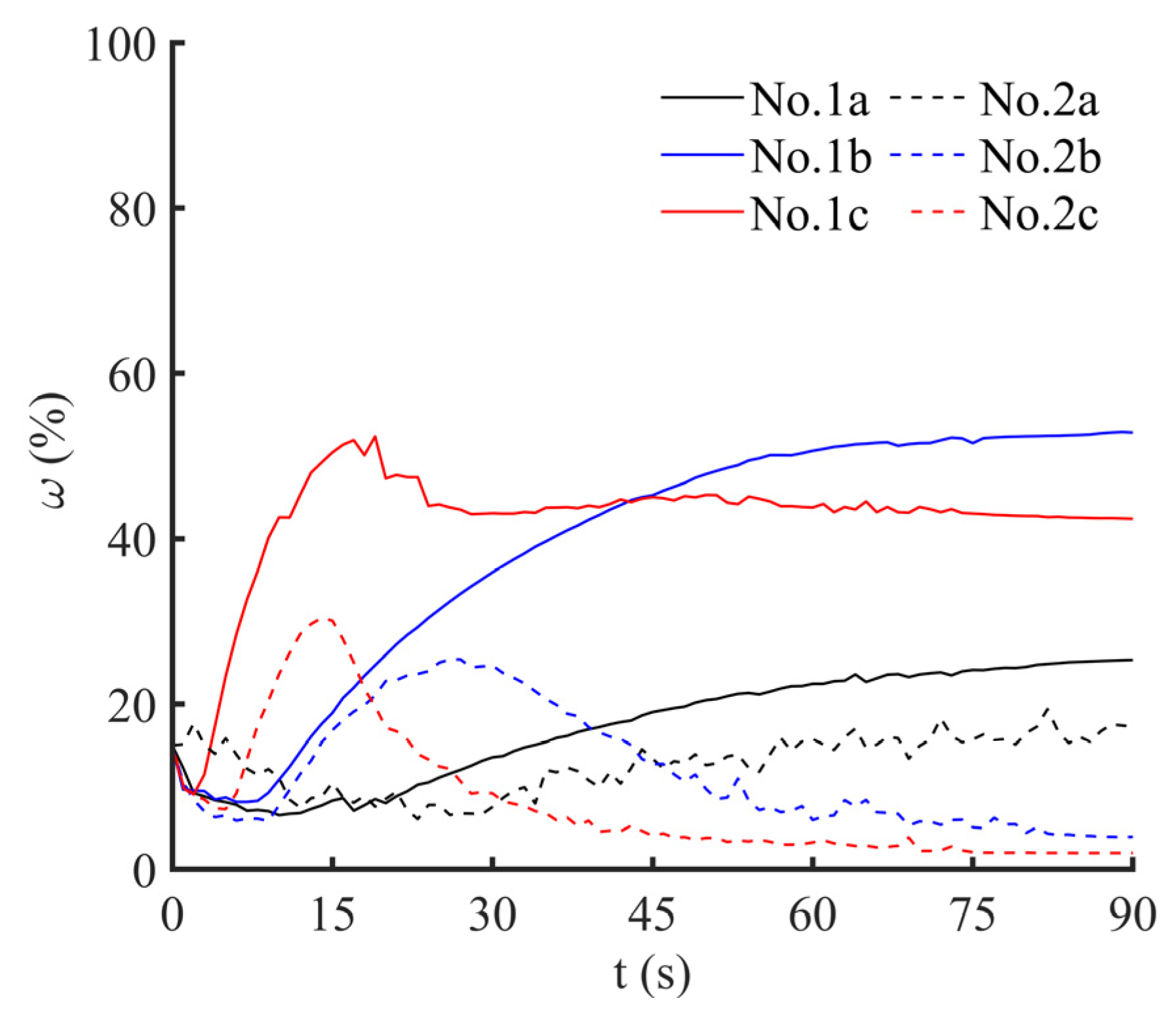
3.3. Results and Discussion

The conversion rate of water head is defined to study the development of excess pore pressure field in the sand, written as:
  ω = H s H 0 H e H s H 0 ,    
where ω is the conversion rate of water head (%), Hs is slurry head (m); H0 = hydrostatic head (m); and He = pore excess water head (m). The conversion rate of water head in the 0–10 cm zone behind the excavation face is expressed as ω 0 10 and the conversion rate of the water head in the 10–40 cm zone behind the excavation face is expressed as ω 10 40 in the following text.
Figure 5 and Figure 6 show the development of ω 0 10 and ω 10 40 , respectively. As shown in Figure 5, for the first infiltration mode—“pure permeable zone”, ω 0 10 continuously increases in the initial stage of infiltration, then it has a continuous slow decline and eventually stabilizes after reaching a turning point. With the increase of injection pressure, the turning point appears faster and ω 0 10 at the turning point is lower. In fact, the turning point is essentially the sign that the slurry infiltration reaches 10 cm behind the excavation face. With the increase of the injection pressure, the slurry takes less time to reach 10 cm behind the excavation face, and the slurry filling effect is reduced in the zone of 0–10 cm. For the second infiltration mode—“filter cake + permeable zone”, the turning point is still the sign that the slurry infiltration reaches 10 cm behind the excavation face, but ω 0 10 experiences a short period of slight attenuation after rising to the turning point and then continues to rise to a high value when the injection pressure is 25 kPa or 50 kPa. In addition, with the increase of the injection pressure, the maximum value of ω 0 10 is higher and the maximum value of ω 0 10 appears in a shorter time. However, when the injection pressure is 10 kPa, no obvious rising turning point appears, and ω 0 10 cannot reach a high value. The reasons for these phenomena are that the filter cake begins to form on the slurry–sand interface when the pores around the slurry–sand interface drop to a certain extent, then a large amount of excess pore pressure is concentrated in the filter cake. However, when the injection pressure is 10 kPa, too low injection pressure cannot form a dense filter cake. Only a small fraction of the excess pore pressure is concentrated in the filter cake, so ω 0 10 does not significantly increase.
As shown in Figure 6, for the first infiltration mode, “pure permeable zone”, ω 10 40 increases to a certain extent and remains stable when the injection pressure is 10 kPa or 25 kPa, and with the increase of injection pressure, the final stable value of ω 10 40 is higher. However, when the injection pressure is 50 kPa, a slight attenuation occurs after rising to a turning point. The reason for this phenomenon is that, with the increase of injection pressure, the final slurry infiltration distance is further. When the injection pressure is 10 kPa or 25 kPa, the final slurry infiltration distance is less than 40 cm or around 40 cm, so the final stable value of ω 10 40 is higher when the final slurry infiltration distance is further. However, the final slurry infiltration distance is 65 cm when the injection pressure is 50 kPa, and the infiltrated zone after 40 cm occupies part of the excess pore pressure, which results in a slight drop of ω 10 40 after rising to a turning point. For the second infiltration mode, “filter cake + permeable zone”, ω 10 40 drops to a very low value after rising to a turning point when the injection pressure is 25 kPa or 50 kPa. However, when the injection pressure is 10 kPa, ω 10 40 increases slowly until it stabilizes. The essential reason for this phenomenon is that the formation of filter cake leads to the redistribution of excess pore pressure, the dense filter cake can occupy most of the excess pore pressure, but the evacuated filter cake can only occupy a small part of the excess pore pressure.
The development curves of ω 0 10 and ω 10 40 further prove the correctness of dividing the two infiltration modes into the “pure permeable zone” and “filter cake + permeable zone”. According to Talmon’s study [22], there is an undrained behavior in the slurry during mud spurt and a drained behavior during external cake formation. The transition is determined by the Peclet number (Pe), which they define for this situation as:
  P e = v p d c v ,  
where vp is the pore fluid velocity; d is the hydraulic pore diameter; and cv is the console- dation coefficient of the bentonite slurry. However, the formation of filter cake also has its prerequisites. Mao [23] indicated that the filter cake can only be formed on the surface of the excavation face after the porosity around the excavation face decreases to a limit value. For the first infiltration mode, ”pure permeable zone”, as the slurry infiltrates into the saturated sand, small pores in the infiltrated sand are effectively filled with the bentonite while the large pores cannot be effectively filled, so the permeability coefficient of the infiltrated sand drops to a fixed value and stabilizes. With the increase of slurry infiltration distance, the flow resistance of the sand constantly increases and slurry infiltration speed constantly decreases, but the porosity around the excavation face is still too large to form the filter cake. Eventually, a stable pure permeable zone is formed, and the conversion rate of the water head is closely related to the zone infiltrated by the slurry, part of the excess pore pressure between the slurry and the hydrostatic water is evenly distributed in the infiltrated zone, and the other part is distributed in the zone which is not infiltrated by the slurry. However, for the second infiltration mode, “filter cake + permeable zone”, some large pores can be filled while the small pores in the strata are filled, but the filter cake dost not start to form on the slurry–sand interface in the initial stage of infiltration, so in the initial stage of infiltration, the distribution of the excess pore pressure is similar to that of the first infiltration mode. With the slurry infiltration, the filter cake begins to form when the Peclet number reaches a critical value, and the excess pore pressure gradually accumulates around the slurry–sand interface. When the filter cake is completely formed, the ω 10 40 can reach nearly 90%, and the conversion rate of the zone which has not been infiltrated and has been infiltrated by slurry is very small. Comparing these two infiltration modes, it should be noted that, although the strata used in the experiment belong to the same type of sand according to Code for Investigation of Geotechnical Engineering, the distribution of excess pore pressure field is very different. Therefore, the same types of sand according to the Code for Investigation of Geotechnical Engineering cannot be simply treated to have the same permeability and the similar distribution of excess pore pressure, since whether the filter cake can be formed and the quality of the filter cake are the key factors to determine the distribution of the excess pore water pressure.

4. Local Stability of the Trench Walls in the Process of Excavation Located in High Permeability Saturated Sand

When the underground continuous wall is constructed, the underground continuous wall is divided into several construction units of a certain length along the length direction of the wall in advance, and each construction unit is called the unit slot. In addition, in one unit slot, the jump-excavation method generally is adopted. As shown in Figure 7, a unit slot is divided into three grabs for the excavation. One excavation operation only can grasp a certain depth of soil in one grab, and the strata in Grab III begin to be excavated after the strata in Grab II and Grab I have been completely excavated to the bottom. The local instability generally exists in the following three cases: Case1: After a unit slot has been completely excavated to the bottom, the local instability occurs in the whole weak interlayer due to the long shelving time. Case2: In the process of excavation located in Grab II or Grab III, the local instability in the whole weak interlayer occurs in Grab I due to construction disturbance. Case3: The local instability occurs in the process of excavation located in the weak interlayer for the single grab. In addition, this paper mainly studied the local instability of Case3.

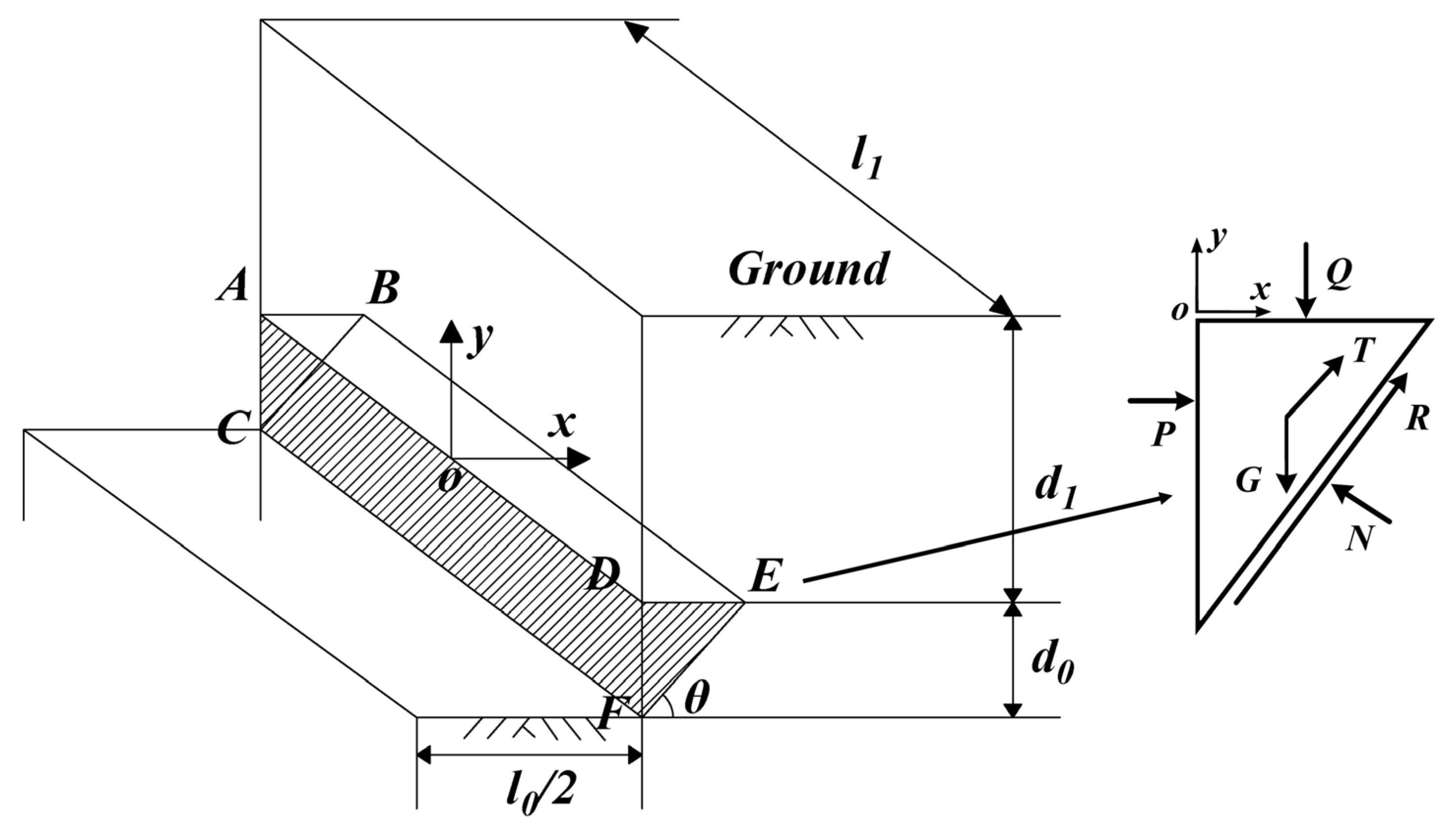
4.1. Local Instability Model

As shown in Figure 8, a three-dimensional wedge-shaped model was constructed to analyze the local stability of the slurry trench. The height, width, and failure angle of the instability wedge ABCDEF is d0, l1 and θ, respectively, d1 represents the thickness of the superstratum, and l0 represents the width of the slot. The force diagram of the unstable wedge is also shown in Figure 8, including the self-weight G of the unstable wedge, the effective support force P, the overburden Q from the superstratum, the lateral friction force T, and the slope friction force R.

4.2. The Calculation of Safety Factor for the Local Stability

The conventional local stability model of the slurry trench is generally adopted for calculation under Case1. Under this condition, the unstable body is regarded as the whole weak interlayer, the height of the instability body is the height of the entire weak interlayer, the width of the instability body is the width of the unit slot, and the slurry infiltration reaches a steady state because the slurry has infiltrated for a long time. However, in Case3, the width of the instability body is the width of a grab, and the height of the unstable body depends on the excavation depth of the grab in the weak interlayer. In this paper, only the depth of one excavation operation is considered. In addition, it should be noted that the slurry infiltration is not a steady state because the slurry just begins to infiltrate into the stratum after one excavation operation. In this calculation, the value of the effective support pressure was based on the experimental results of the third chapter, although the penetration path in the experiment is a fixed value of 1.7 m, which is different from the semi-infinite boundary in practical engineering. It can be found in the experiment that most of the excess pore pressure is concentrated in the zone infiltrated by the slurry, and, through numerical simulation analysis [9], the influence range of excess pore pressure is only within a certain range ahead of the excavation surface, and the proportion of excess pore pressure decreases with increasing distance from the excavation face. Therefore, it is approximately considered that the excess pore pressure field obtained in the experiment is the real excess pore pressure field.
According to the construction conditions of the jump-excavation method, it is assumed that the depth, width, and failure angle of one excavation is 0.7 m, 3 m, and (45 + φ/2)° (φ represents the friction angle of sand), respectively. Because a precipitation treatment is generally adopted before the slot is excavated, the groundwater level is assumed to be 2 m below the ground. Too low injection pressure generally cannot occur, so the injection pressure 10 kPa in the experiment is not considered, and the rest of the injection pressure corresponds to the slot depth. In addition, the unit weight of the soil above the groundwater level is 18 kN/m3, and the effective unit weight of the saturated soil below the groundwater level is 10 kN/m3. Three slurry infiltration modes and two slot depths were chosen in the calculations presented in Table 5.
The sensitivity analysis of the local stability in the process of excavation located in high permeability saturated sand to the ground overload and friction angle of the sand when the slurry infiltration is approximately stable is presented in Figure 9 and Figure 10. As shown in Figure 9 and Figure 10, the safety factor for the local stability decreases with the increase of the ground overload and decrease of the friction angle for three slurry infiltration modes, and the influence of ground overload on the safety factor for the local stability located in the shallow strata is more obvious. Compared with the slurry infiltration mode I, which does not consider the reduction of the support pressure, different degrees of support pressure reduction occur for slurry infiltration modes II and III. In addition, for the slurry infiltration mode II, the value of the support pressure reduction is smaller than that for the slurry infiltration mode III, and no matter how the ground overload, slot depth, and friction angle are changed, the safety factor for the local stability can remain above 1.1, and the safety factor for the local stability located in the deep strata is larger than that located in the shallow strata. However, for the slurry infiltration mode III, no matter how the ground overload, slot depth, and friction angle are changed, the safety factor for the local stability always remains below 1, and the safety factor of the local stability located in the shallow strata is larger than that located in the deep strata. The reason for this phenomenon is that, for slurry infiltration modes II, according to the distribution of excess pore pressure from the experiment, the excess pore pressure is mainly concentrated on the filter cake, so most of the support pressure can be converted into the effective support pressure, which acts on the unstable body, but for the slurry infiltration mode III, the excess pore pressure is mainly distributed in the infiltrated zone and the zone which has not been infiltrated. If the support pressure exceeds the range of the instability body, it will fail, so only part of the support pressure can be converted into the effective support pressure.
Figure 11 shows the safety factor for local stability in the process of excavation located in high permeability saturated sand against time for the slurry infiltration modes II and III. In this calculation, it is assumed that the friction angle of the sand is 30° and the ground overload is 20 kPa. As shown in Figure 11, the safety factor for local stability during the excavation is not a fixed value, it is a time-dependent value, and, for the slurry infiltration mode II, the safety factor increases with the slurry infiltration, and the safety factor can reach 1 around 10 s. Then, with the gradual formation of the filter cake, the safety factor will continue to increase to a higher value. However, for the slurry infiltration mode III, the safety factor also increases with the slurry infiltration, but the maximum value to which the safety factor can increase is less than 1 because no filter cake can be formed on the excavation face.
Through the above calculation, the internal friction angle of sand, overload, and slot depth also affect the safety factor, but the formation of the filter cake for the slurry infiltration mode is most important for the local stability in the process of excavation located in high permeability saturated sand of diaphragm wall construction. For the slurry infiltration mode II, the filter cake can be formed on the trench walls, and the local stability of the slurry trench in the process of the excavation located in high permeable strata can be guaranteed. However, if the slurry infiltration mode III is encountered in the process of the excavation located in high permeable strata, the wedge-shaped unstable body of each excavation step in the whole weak interlayer will be accompanied by the risk of local instability, and the accumulation of these small local instabilities may eventually lead to a wider range of local instability in the weak interlayer. In the actual underground continuous wall project, if the sand layer with a particle size range of 0.5–1.0 mm is simply regarded as the same type of sand according to Code for Investigation of Geotechnical Engineering, the same construction method and treatment measures are adopted during the trench excavation, and there may be a risk of local instability for some strata.

5. Conclusions

The distribution of excess pore pressure in the high permeability strata, which adopted an initial hydraulic gradient comparable to real trench excavation, and the local instability of the slurry trench in the process of excavation located in high permeability saturated sand have been presented in this paper. From these investigations, the following conclusions can be drawn:
(a)
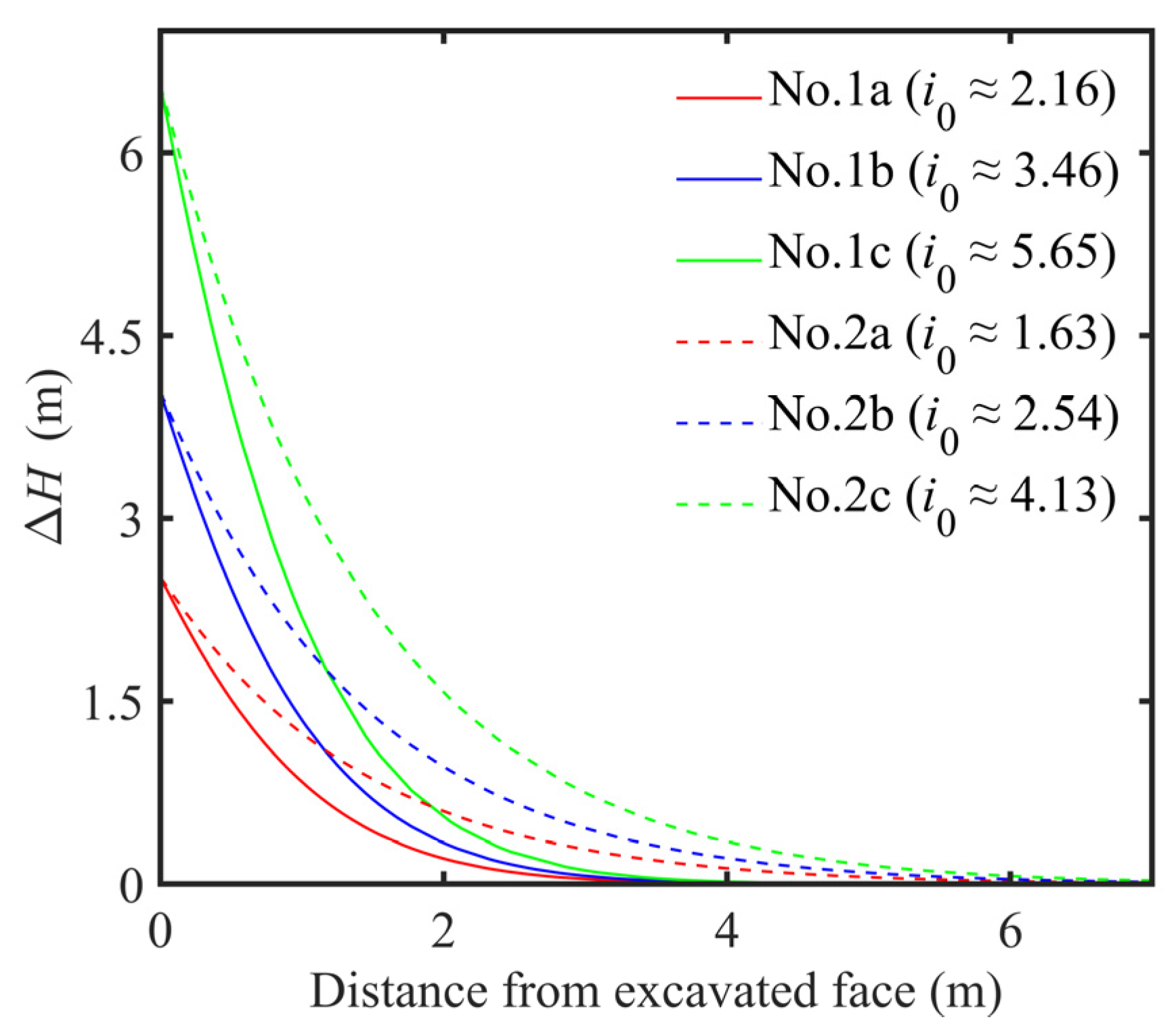
According to the results of the numerical simulation, the initial hydraulic gradient in the process of excavation is much smaller than that adopted in the traditional experiments. In addition, the initial hydraulic gradient is different under different working conditions. In the different working conditions listed in this paper, the difference in the initial hydraulic gradient reaches around 3.5 times.
(b)
Even if the strata used in the experiment belong to the same type of sand specified in the Code for Investigation of Geotechnical Engineering, two different distributions of the excess pore pressure occur in the strata, the formation of the filter cake has a great influence on the distribution of excess pore pressure. For the slurry infiltration mode where the filter cake can form, the excess pore pressure gradually accumulates to the excavation face, and finally most of the excess pore pressure will completely accumulate on the excavation surface. However, for the slurry infiltration mode where the filter cake cannot form, the excess pore pressure is continuously redistributed in the infiltrated zone and the zone which is not infiltrated by the slurry, and finally most of the excess pore pressure is concentrated in the zone infiltrated by the slurry, and a small part is concentrated in the zone which is not infiltrated by the slurry. Thus, it cannot be simply considered that the same type of sand specified in the Code for Investigation of Geotechnical Engineering has the same permeability; whether the filter cake can be formed and the quality of the filter cake are the key factors to determine the distribution of the excess pore pressure.
(c)
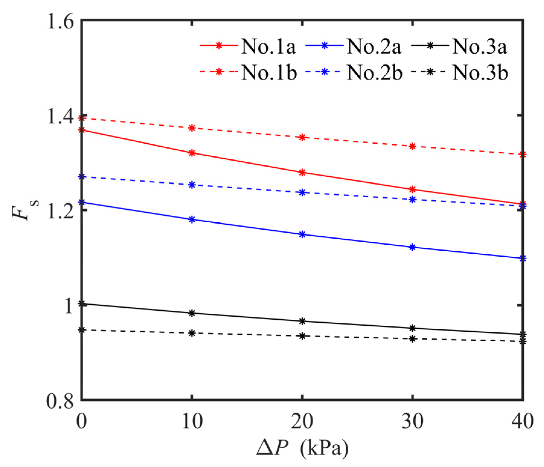
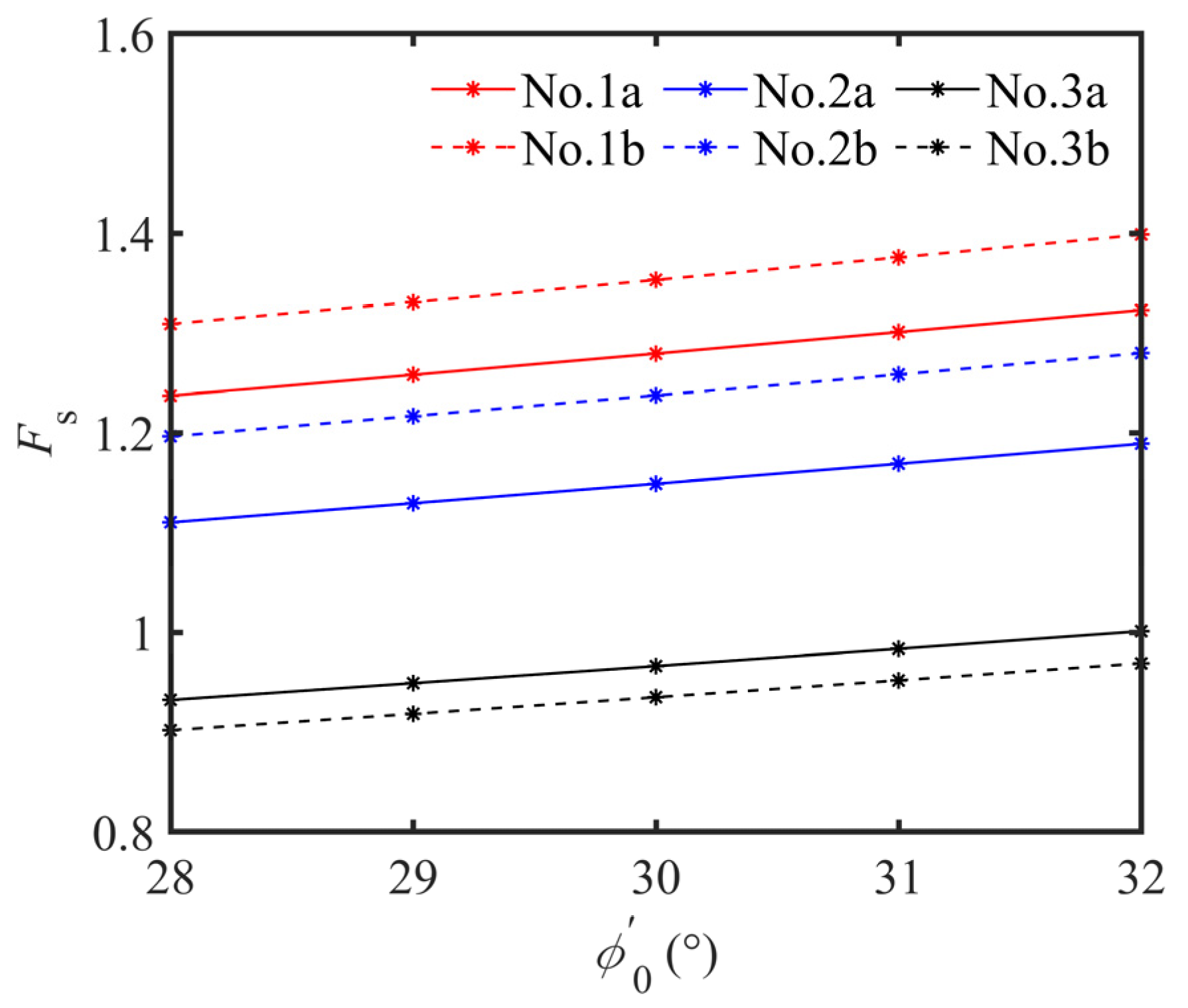
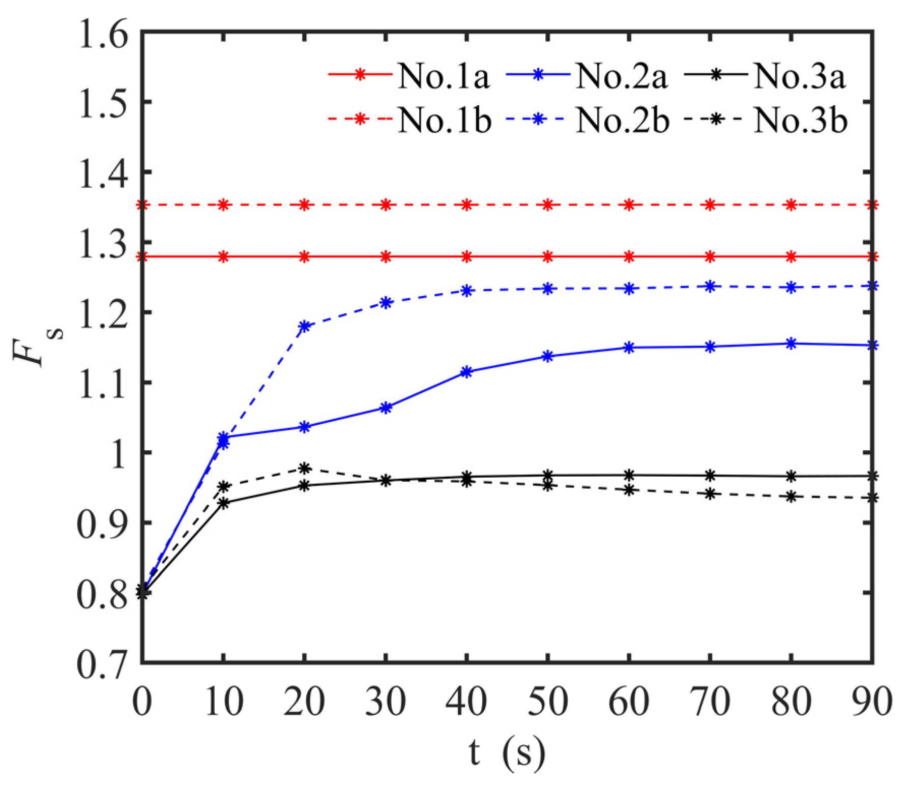
Reduction of support pressure is different for the two infiltration modes presented in this paper. Although the internal friction angle of sand, overload, and slot depth also affect the safety factor, the formation of the filter cake for the slurry infiltration mode is crucial for local stability in the process of excavation located in high permeability saturated sand of diaphragm wall construction. Attention should be paid to the local stability in the process of excavation located in high permeability saturated sand when the slurry infiltration mode is the pure permeable zone, and the effective support pressure acting on the unstable body may not guarantee the local stability in the process of excavation located in high permeability saturated sand.

Author Contributions

Y.L.: wrote the main manuscript text, including figures and tables. L.W.: contributed to the conception and design of the research, data analysis. Y.Z.: revised the manuscript. X.Z.: performed the collection of data. All authors have read and agreed to the published version of the manuscript.

Funding

This research received no external funding.

Data Availability Statement

The datasets generated during the current study are available from the first author on reasonable request.

Conflicts of Interest

The authors declare that there is no conflict of interest.

References

  1. Wong, G.C. Stability analysis of slurry trenches. J. Geotech. Eng. 1984, 110, 1577–1590. [Google Scholar] [CrossRef]
  2. Zhang, F.; Gao, Y.F.; Leshchinsky, D.; Zhu, D.S.; Lei, G.H. Three-dimensional stability of slurry-supported trenches: End effects. Comput. Geotech. 2016, 74, 174–187. [Google Scholar] [CrossRef]
  3. Wang, H.; Huang, M. Upper bound stability analysis of slurry-supported trenches in layered soils. Comput. Geotech. 2020, 122, 103554. [Google Scholar] [CrossRef]
  4. Liu, W.; Shi, P.; Cai, G.; Gan, P. A three-dimensional mechanism for global stability of slurry trench in frictional soils. Eur. J. Environ. Civil. Eng. 2022, 26, 594–619. [Google Scholar] [CrossRef]
  5. Tan, T.; Huang, M.; Shi, Z. Analytical Three-Dimensional Mechanism for Stability of Slurry Trenches in Cohesive Soils. Int. J. Geomech. 2022, 22, 04021274. [Google Scholar] [CrossRef]
  6. Han, C.-Y.; Wang, J.; Xia, X.-H.; Chen, J.-J. Limit Analysis for Local and Overall Stability of a Slurry Trench in Cohesive Soil. Int. J. Geomech. 2012, 15, 06014026. [Google Scholar] [CrossRef] [Green Version]
  7. An, C.-L.; Feng, W.-X.; Zhao, Q.-H.; Ji, L.-L.; He, D.-L.; He, B.-G. Local Stability of Trench for Diaphragm Walls Passing through Deep Weak Interlayer. Adv. Mater. Sci. Eng. 2021, 2021, 9934516. [Google Scholar] [CrossRef]
  8. Liu, Y.; Liu, W. Local instability analysis of the ultra-deep wall-to-slotted in water rich soft layer. Chin. J. Rock Soil Mech. 2020, 41, 1000–7598. [Google Scholar]
  9. Zizka, Z.; Schoesser, B.; Popovic, I.; Thewes, M. Excess pore pressures in front of the tunnel face during slurry shield excavations due to different time scales for excavation sequence of cutting tools and penetration time of support fluid. In Proceedings of the ECONAS Conference EURO, Innsbruck, Austria, 18–20 April 2017. [Google Scholar]
  10. Broere, W.; Van Tol, A. Time-dependant infiltration and groundwater flow in a face stability analysis. In Modern Tunneling Science and Technology; CRC Press: Boca Raton, FL, USA, 2020; pp. 629–634. [Google Scholar]
  11. Filz, G.M.; Adams, T.; Davidson, R.R. Stability of long trenches in sand supported by bentonite-water slurry. J. Geotech. Geoenviron. Eng. 2004, 130, 915–921. [Google Scholar] [CrossRef]
  12. Muller-Kirchenbauer, H. Stability of slurry trenches. In Proceedings of the 5th European Conference on Soil Mechanics and Foundation Engineering, Madrid, Spanish, 10–13 April 1972. [Google Scholar]
  13. Lyu, M. Pore Size Analysis and Its Influence on Slurry Infiltration in Sandy Layers. Chin. J. Rock Soil Mech. 2020, 3, 144–151. [Google Scholar]
  14. Xu, T.; Bezuijen, A. Pressure infiltration characteristics of bentonite slurry. Géotechnique 2019, 69, 364–368. [Google Scholar] [CrossRef]
  15. Xu, T.; Bezuijen, A. Analytical methods in predicting excess pore water pressure in front of slurry shield in saturated sandy ground. Tunn. Undergr. Space Technol. 2018, 73, 203–211. [Google Scholar] [CrossRef]
  16. Saada, Z.; Canou, J.; Dormieux, L.; Dupla, J.-C.; Maghous, S. Modelling of cement suspension flow in granular porous media. Int. J. Numer. Anal. Methods Geomech. 2005, 29, 691–711. [Google Scholar] [CrossRef]
  17. Xu, T.; Bezuijen, A. Bentonite slurry infiltration into sand: Filter cake formation under various conditions. Geotechnique 2019, 69, 1127. [Google Scholar] [CrossRef]
  18. Zizka, Z.; Schoesser, B.; Thewes, M. Excavation cycle dependent changes of hydraulic properties of granular soil at the tunnel face during slurry shield excavations. In Geotechnical Aspects of Underground Construction in Soft Ground; CRC Press: Boca Raton, FL, USA, 2017; pp. 137–144. [Google Scholar]
  19. API (American Petroleum Institute). Recommended Practice Standard Procedure for Field Testing Water-Based Drilling Fluids, 3rd ed.; 13B-1; API (American Petroleum Institute): Washington, DC, USA, 2003. [Google Scholar]
  20. EN-1538; Execution of special geotechnical works—Diaphragm walls. CEN (Comité Européen de Normalisation): Brussels, Belgium, 2000.
  21. GB50021; Chinese Code for Investigation of Geotechnical Engineering. Ministry of Construction of the People’s Republic of China: Beijing, China, 2009.
  22. Talmon, A.M.; Mastbergen, D.; Huisman, M. Invasion of pressurized clay suspensions into granular soil. J. Porous Media 2013, 16, 351–365. [Google Scholar] [CrossRef]
  23. Yuan, M. A theoretical study of porosity characteristics on the excavation face of slurry shield in sand stratum. Chin. J. Rock Soil Mech. 2020, 41, 1000–7598. [Google Scholar]
Figure 1. Numerical model of the trench excavation of a diaphragm wall in COMSOL.
Applmech 03 00072 g001
Figure 2. Contour of the initial hydraulic field.
Applmech 03 00072 g002
Figure 3. Device for of pressure infiltration of bentonite slurry.
Applmech 03 00072 g003
Figure 4. Grain size distribution of fresh slurry.
Applmech 03 00072 g004
Figure 5. Development of ω 0 10 against time.
Applmech 03 00072 g005
Figure 6. Development of ω 10 40 against time.
Applmech 03 00072 g006
Figure 7. Jump-excavation method during the trench excavation.
Applmech 03 00072 g007
Figure 8. The local failure model of the slot at the diaphragm wall.
Applmech 03 00072 g008
Figure 9. Relationship between the safe factor of local stability and ground overload.
Applmech 03 00072 g009
Figure 10. Relationship between the safe factor of local stability and friction angle of sand.
Applmech 03 00072 g010
Figure 11. Safety factor for the local stability against time.
Applmech 03 00072 g011
Table 1. Properties of clay and sand used in the simulation.
Type of SoilParticle Size (mm)PorosityIntrinsic Permeability (m2)Bulk Modulus (MPa)
Sand I0.25–0.50.357.7 × 10−1140
Sand II0.5–10.451.5 × 10−1040
Clay-0.51 × 10−1410
Table 2. Simulation program.
Type of SoilParticle Size (mm)Slot Depth (m)Slurry Weight (kN/m3)No. of Simulation
Sand I0.25–0.501010.51a
2011.01b
3011.51c
Sand II0.5–1.01010.52a
2011.02b
3011.52c
Table 3. Fresh slurry properties in the tests.
Bentonite Concentration (g/L)Pure Alkali Concentration (%)Density (g/cm3)Marsh Time (s)Soviet Time (s)PH
4041.0439309.5
Table 4. Experimental program.
SlurrySlurry Infiltration ModeInjection Pressure (kPa)No. of Experiment
B1, 4%Pure permeable zone101a
251b
501c
Filter cake + permeable zone102a
252b
502c
Table 5. Calculation program.
Slurry Infiltration ModeSlot Depth (m)Pressure (kPa)No. of Calculation
I: Method without considering the time effect and pressure reduction10251a
30501b
II: Filter cake + permeable zone10252a
30502b
III: Pure permeable zone10253a
30503b
Publisher’s Note: MDPI stays neutral with regard to jurisdictional claims in published maps and institutional affiliations.

