2. Related Work
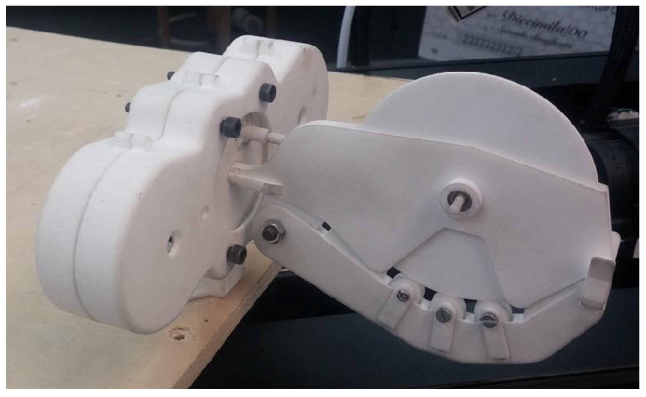
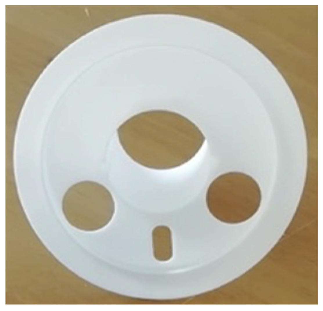
The project to develop a robot for angioplasty dates back to 2013 with the idea of using a gear train made of two big gears, of which one is hollow and provided with internal teething to advance and retract a catheter while being able to turn it about its axis. In order to obtain translations, it was decided to use a couple of gears mounted on the same axis, which were free to rotate but fixed in position with respect to the front gear. Of these gears, one was a spur gear that mashed with a hollow gear, and the other, a bevel, mashed with an external device containing friction wheels. This external device was planned from the very beginning to be a disposable, sterile element that had to interface between the gearing and the catheter. Initially, the knowledge of how Corindus Cor-Path was made was limited. In the first version of the prototype, the rotation of the disposable element around its axis was obtained by wrapping it around a disk that could rotate. Nevertheless, during initial testing, it was clear that this approach would have required longer catheters for optimal functioning. In order to advance and retract these devices, friction wheels were used and coupled with the bevel gears, resulting in a two-gear assembly. Relatively rough surfaces (without damaging the catheters) were key to obtaining optimal performance, together with well-calibrated forces acting on the friction wheels, for which it was decided to use springs.
Figure 1 presents the first system built, including the disposable, characterized by the big wheel.
After the initial tests were performed with the medical team of Magna Graecia University, it was clear that it was necessary to move two devices independently at the same time: one 0.014″ diameter wire and one catheter (either balloon catheter or stent delivery catheter). The two devices share a common initial portion, but separate into two different grooves after few centimeters. Thus, this version of the prototype used three big gears, of which two were hollow carrying internal teething. As a consequence of these changes, it was necessary to add a tubular extension to the disposable outlet to warrant the sterility of the devices, to avoid contact with any part of the Robotic Actuator (RA), except the sterile disposable. In addition, the tubular extension was dressed with a removable cap, to preserve its sterility during its insertion into the RA.
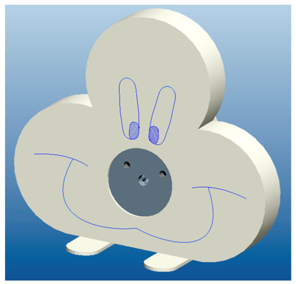
As the disposable element became longer, after the changes just described, it was necessary to further modify the prototype to minimize the engagement tract of the operated devices (wire and catheters). For this reason, and in order to control the rotation of three different gears, the RA ended up presenting a three-lobed shell, which was designed to look similar to the Sylvester cat to be more user-friendly (
Figure 2). In this version of the prototype, the disposable element looked similar to the “nose” of Sylvester. Hence, this became the term to identify the Disposable for Angioplasty (DA), that was named, for a while, as “nose”.
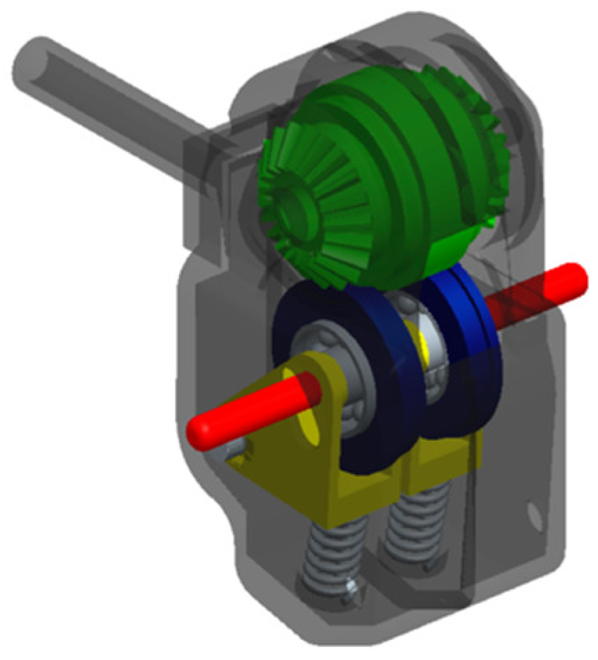
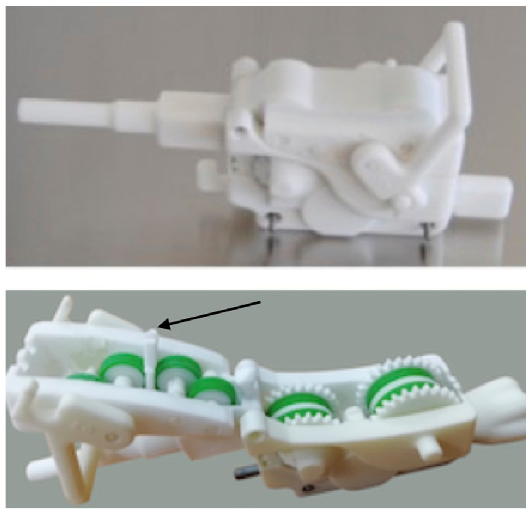
Figure 3 depicts the new version of the DA. As can be seen in the figure, the upper friction wheel (green) is coupled with the bevel gear, while the lower is placed on a small frame (yellow), pushed by a spring, which can be dislodged pressing on an external protrusion (red) in order to introduce the catheters. Since there were two very close parallel friction wheels, the external protrusion had to be eccentric with respect to the frame. Keeping in mind that the overall dimensions of the disposable were small, pressing on the external protrusion deformed the small internal frame, and this caused improper coupling between the friction wheels.
To try overcome this problem, a cam with shape coupling was designed, to ensure both the right pressing force between the two friction wheels and the possibility of widening the passage between the wheel to accommodate both devices (wire and catheter).
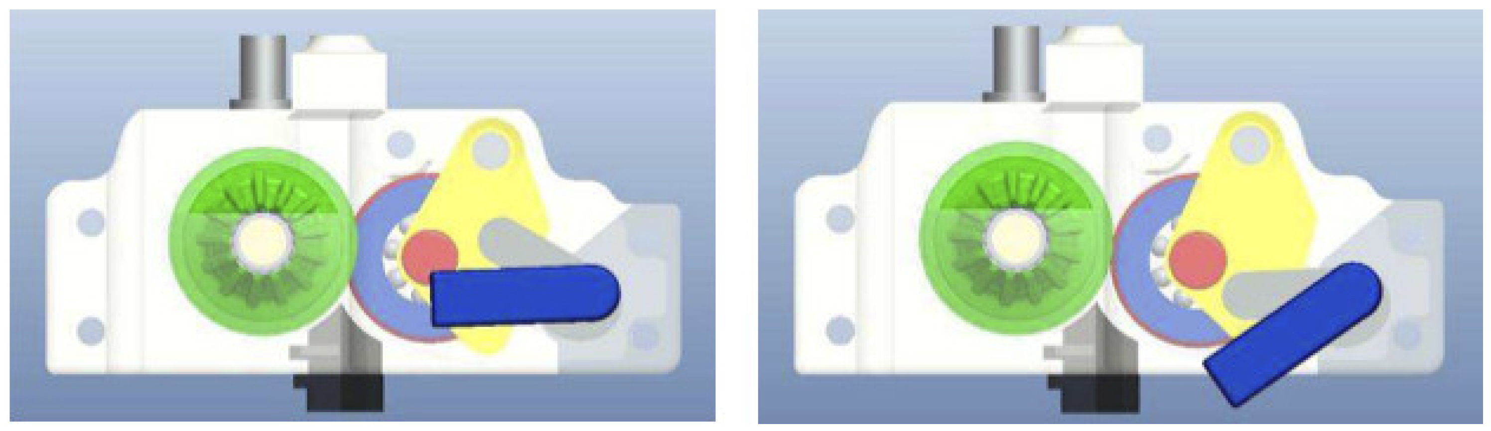
Figure 4 shows the CAD model of this DA.
To understand how the system works, there are two bars, one blue and the second grey, coupled together, which are used to open and close the passages for the catheter and wire. While the blue one was the manual actuator, the grey moved along a carefully designed cavity produced on the yellow frame to dislodge the lower friction wheel, and this occurred without any load. Meanwhile, to close the frame, a second cam, not visible in the drawing, was pushing centrally from underneath the yellow frame, causing a perfect parallelism between the friction wheel axes, overcoming the problem previously described.
Both the DA (Disposable for Angioplasty) depicted in
Figure 3 and the following versions underwent bench tests using real (expired) catheters and guide wires to assess proper functioning and for trouble-shooting. In particular, the two main issues raised during the bench tests were to find the optimal position of friction wheels to warrant the best possible grip on the devices without damaging them and the need to control the rotation of the very thin guide wire. Moreover, it was difficult to control the correctness of the position of both the catheter and guide wire due to limitations in space. Finally the solution adopted was to divide the DA into two components hinged together, one fixed containing the bevel and friction wheels and a second containing a single frame to support the mating friction wheels, which can be opened, exposing the two grooves that accommodate the catheters and guide wires. However, it was soon found that this new version did not have enough grip to warrant the reliable manipulation of the 0.014″ guide wire and, in particular, the safe control of the guide wire rotation. To overcome this problem, we decided to add a second friction wheel (5 in
Figure 5) which was synchronized with the one coupled with the bevel gear (1), using three small spur gears. Moreover, by positioning two small friction wheels (3 and 4) in the region of contact of a relatively big friction wheel (2) that would force the guide wire to assume a curved shape without causing the permanent deformation of the guide wire, a good improvement was implemented. In fact, the use of a large friction wheel was not a possible option, since it would have severely reduced DA opening.
Figure 5 illustrates the concept described above, where (6) identifies the upper friction whell for the catheter.
Finally, having observed that a greater thrust would also be useful for the catheters, the solution of the two synchronized friction wheels was also adopted for the catheters, as shown in
Figure 6, even if, in this case, the friction wheels of the catheter were positioned vertically with respect to those driven by the bevel gear. All this is described in a PCT application [
23] (Patent Cooperation Treaty), international application with possible extension to the entire world), while the mechanism of the RA is described in detail in [
24].
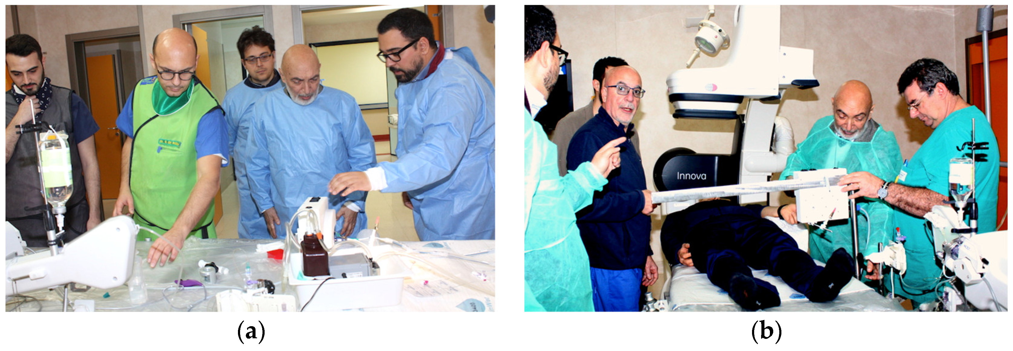
Figure 7a shows the preparation of the first in vitro experiments at Magna Graecia University, Catanzaro, Italy, simulating the coronaries with PVC (Polyvinyl Chloride) tubing filled with water, in order to check the advancement and rotation of the catheter and guide wire, while
Figure 7b shows the first study of the optimal position of the RA. The person on the table was a nurse “spontaneously” assuming the position of a patient.
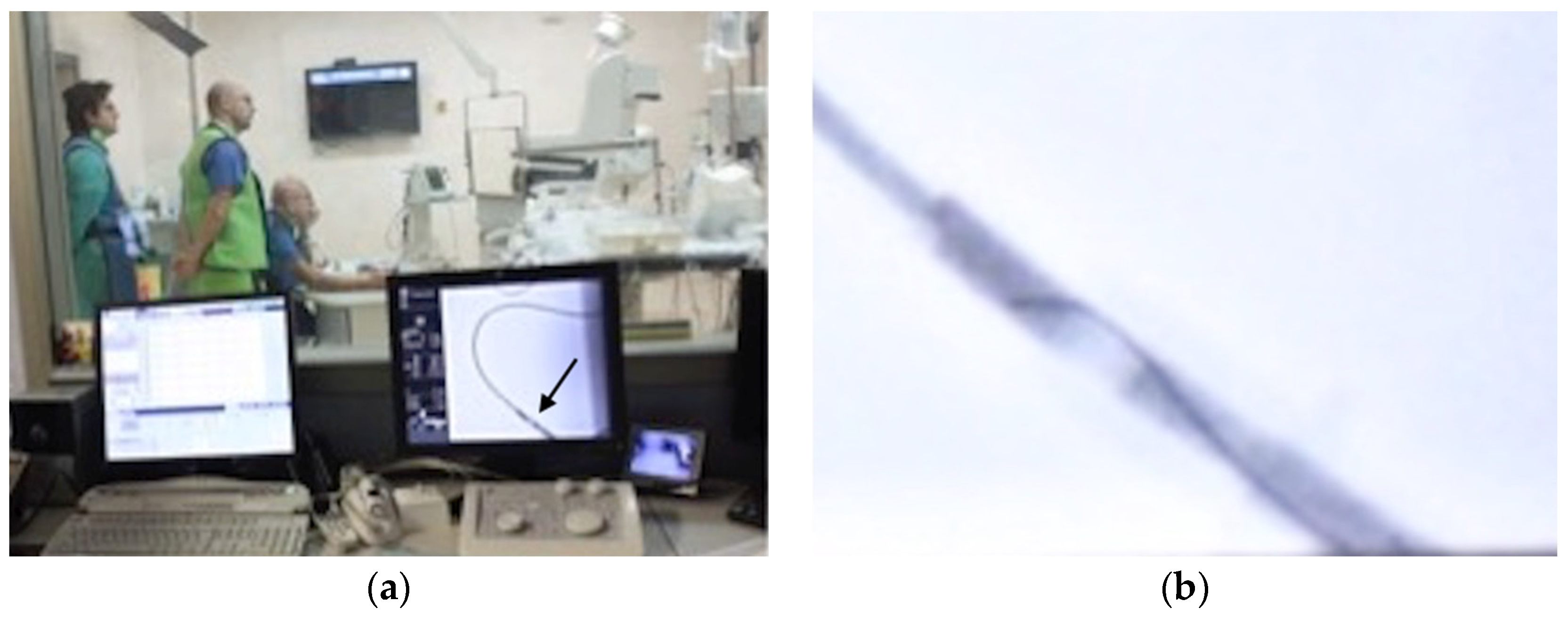
Figure 8 shows two pictures of one of the first trials of the equipment under ionized rays, again using PVC tubing filled with water, and an enlargement of the RX screen showing the guide wire tip.
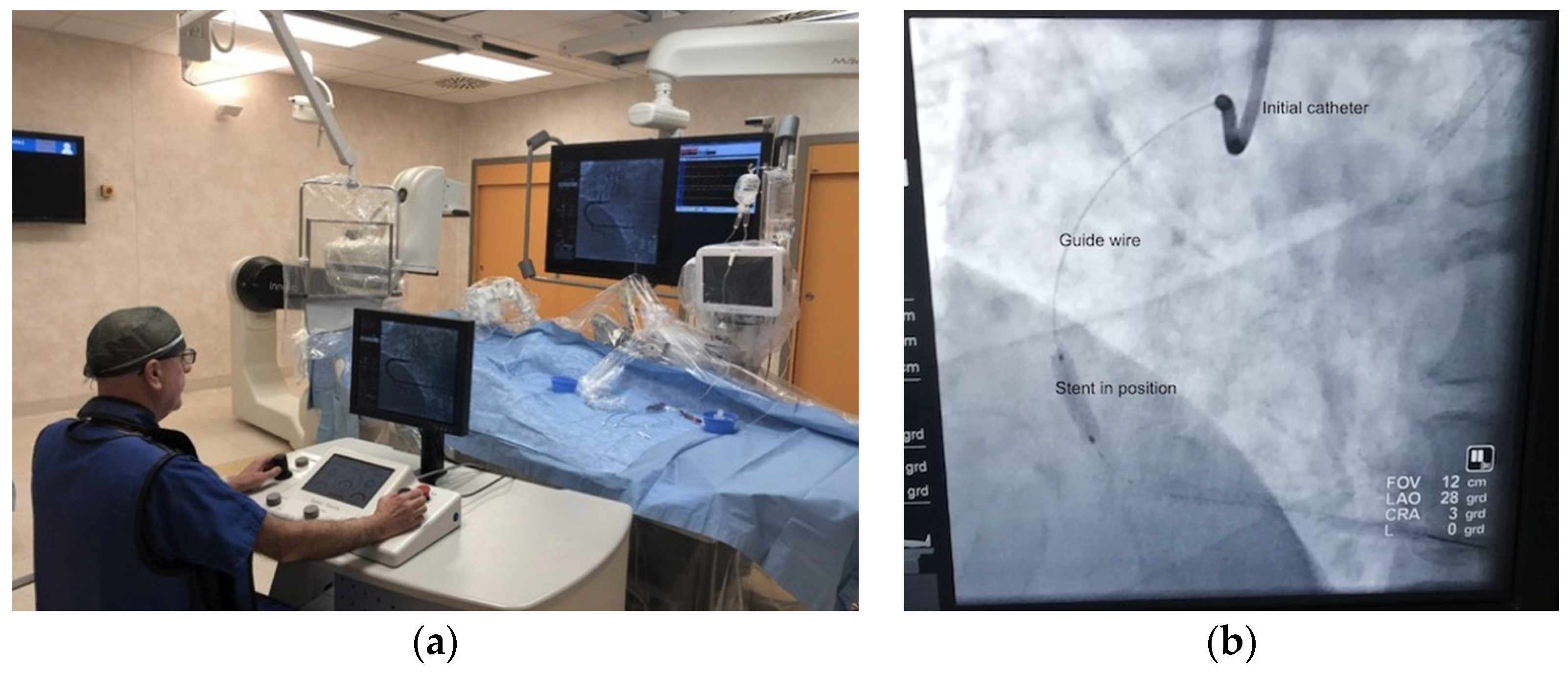
Following the above, it was possible to start the patient trials, once permission was obtained from the Ethics Committee of the University of Magna Graecia. The first surgery occurred on 22 January 2019, during which two stents were inserted in a patient. The trials then continued and are still in progress.
Figure 9a shows the image of the first event, while
Figure 9b shows the stent installed in the heart of another patient in a following surgery (25 February 2021), chosen due to the better quality of the picture.
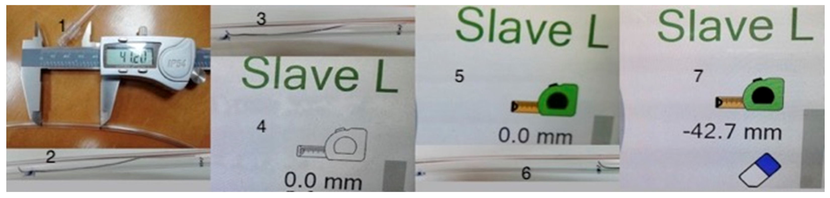
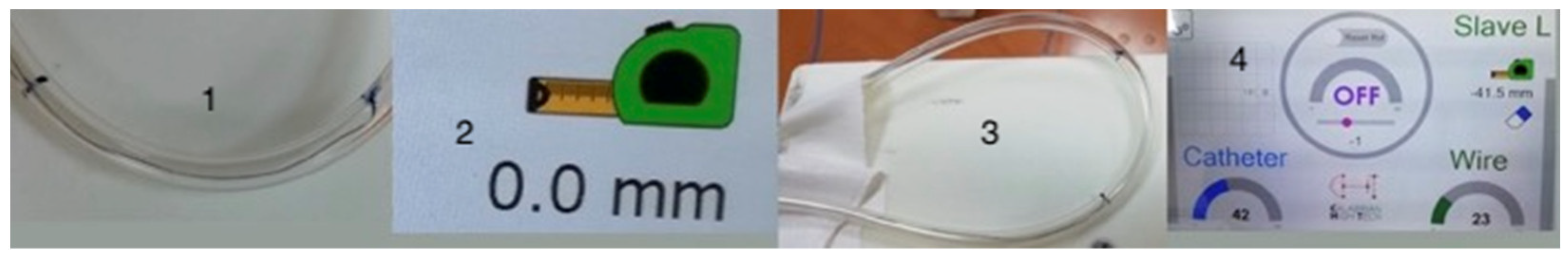
Following a big software revision, an experiment was carried to measure the length of a stenosis to decide the size of the balloon/stent to be used. In fact, since the gearing system is known, and there should be practically no slip between the friction wheels and catheter and guide wire, by counting the motor steps it is possible to compute the distance between two points such as the beginning and the end of the stenosis. This is particularly important since coronaries are spatially curved; thus, linear extrapolation is unfeasible. It is necessary to note that on the right side of the console screen, there is an image which represents a portable measuring tape and an eraser in black and white, which will both turn colorful when pushed once, with the initial inscription of 0.0 mm underneath. This section of the screen is shown in the second, third and fourth thumbnail of
Figure 10, while the full screen is visible in the last thumbnail of
Figure 11. However, if one wants to measure this with a guide wire, since they have very soft and curved tips, the measure should be performed by only pulling the wire, never pushing it. Thus, it is better to advance the wire well above the point where the measure will start, then move it slowly pulling it till it reaches the distal point from which the measure will start, then press the image on the screen showing the measuring tape, which will become colored. Next, pull the wire again until the proximal limit of the stenosis is reached. At this point, the inscription represents the length measured in millimeters, as a negative number, since it was obtained whilst retracting the wire. Touching again the measuring tape, the number is frozen, and to restart you need to touch the eraser, which will produce also the elimination of colours, while zeroing the counter.
Then, a series of eight experiments was carried out, whose results are presented in
Table 1 and in
Figure 10 and
Figure 11, composed of many images pasted together, with
Figure 10 showing an electronic vernier placed on a tubing, on which two black marks have been traced, reporting the distance of 41.2 mm. Then, four measures were made on the straight tubing and four for the curved section. As can be seen from the table, there is no difference between the straight and curved tubing, with an average error of 2.8% difference between the vernier measure and the system measurement, probably due to the compression of the silicon rings covering the friction wheels, which decreases the effective diameter, which can then be corrected. A standard deviation is present, 1.8%, and these numbers demonstrate that the system behaves well.
3. Recent Developments
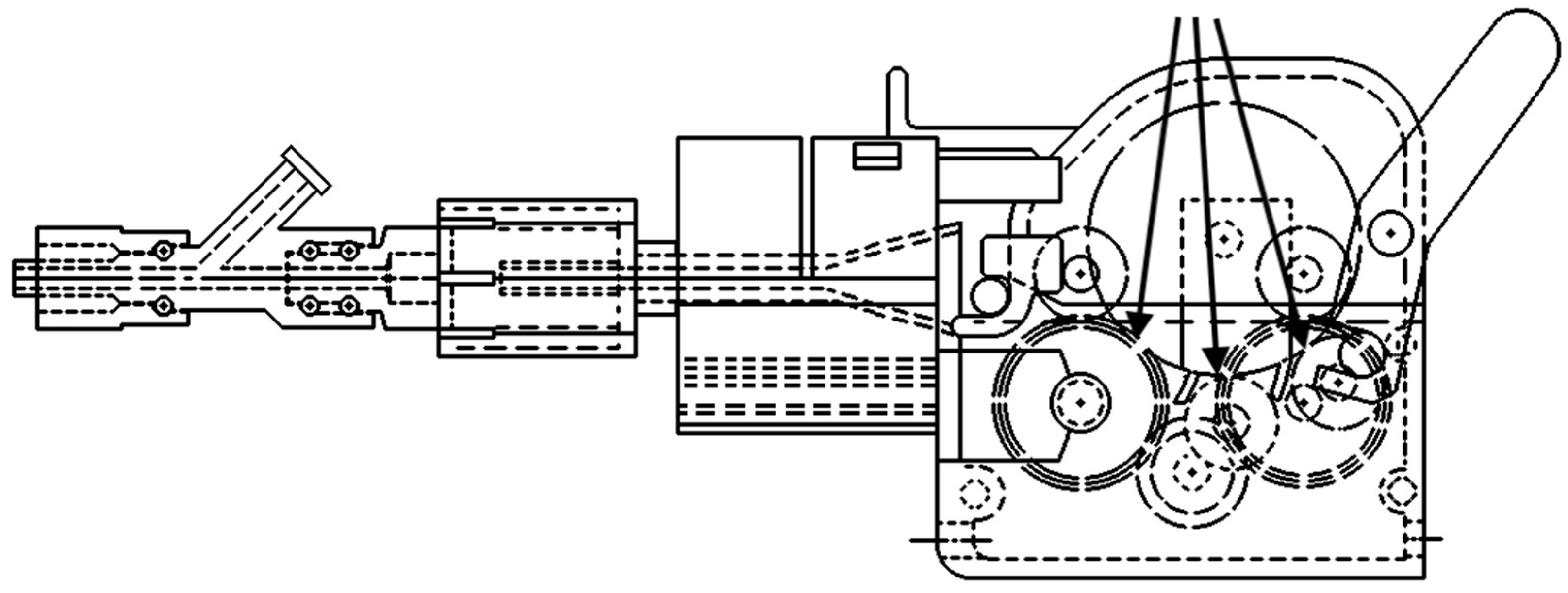
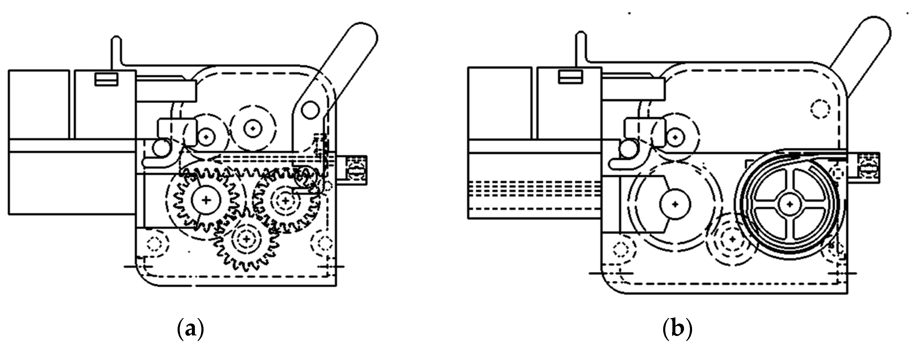
Since the target function of the ROSES prototype had to be extended to endovascular transcatheter surgery, which implies the ability to reach any vascular district, it was clear that it was necessary to couple a catheter and a guide wire, as both are able to rotate independently, thus using two RA in the series. Moreover, while for endovascular surgery it is sometimes necessary to use large-sized catheters, the need for a larger passage through the RA was also clear. Furthermore, sometimes, for instance in the case of large aneurisms, it is necessary to first reach the right location using a normal-sized catheter and guide wire, and then eliminate the catheter to mount, on the guide wire left in position, the larger catheter carrying the stent. This made clear that it was necessary to allow the extraction of the disposable used to first push the initial catheter and also the hemostasis valve. Hence, on one side, the disposables, rather than having an upper and lower component hinged together, had to be completely separated. On the other, to allow the hemostasis valve to pass through the RA, the passage hole had to be at least 36 mm in diameter rather than the previous 7 mm. This created the need for a complete redesign of the central gear train, by changing the number of teeth of the mechanism of the three concentric gears from 70 to 97, while increasing the number of teeth of the hollow gear from 53 to 78, separating the three gears as before with the ball bearings of a larger size, also reducing the number of teeth on the internal gears meshing with the ring from 21 to 19, also adding a small reductor to each motor. This required a change in the transmission ratio in the software; however, in reality, the working principle and electronic control are unchanged. The new RA is thus shown in
Figure 12 [
24], together with the previous editions [
25,
26] from the initial configuration in which the motors were positioned parallel to the main gear’s axis, to the last model presenting the 36 mm central passage.
However, while the initial idea was to keep the two RAs in a fixed position, it was soon realized that this was not possible, since the catheter could turn around its axis a number of times, risking touching non-sterile parts.
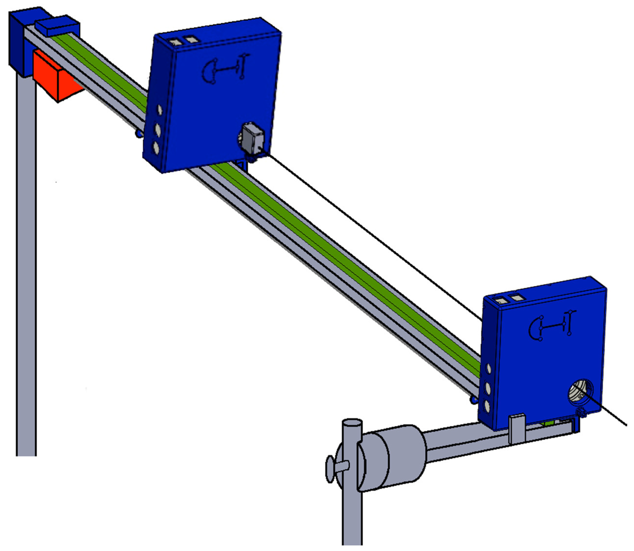
Moreover, since the guide wire had to be inserted in the catheter from the beginning and not all guides are very flexible, this could cause more problems. Hence, we decided to develop a new cart dedicated to the RA in the series, where the RA dedicated to the guide wire is positioned far enough so that the catheter is kept straight, with the guide wire initially introduced in it to be just about to exit from the catheter. Then, as the catheter is introduced in the patient, the RA holding the guide wire is advanced at the same speed of the catheter, so that the doctor at the console may simply rotate the two independently moving sidewise each joystick, only commanding variation in the relative position between the guide and catheter with the wire joystick moved vertically, while advancement is commanded by the catheter joystick with vertical motion. This is shown in
Figure 13 [
27].
Note in this picture that there is a stainless rectangular profile (grey) slightly inclined toward the patient, held both near the patient on the side of the operatory bed, and whose vertical position is ensured by a vertical bar of adjustable height fixed to a wheeled tripod at the very end of the profile. A rail (green) is fixed on this profile, on which, in this case, there are three small slides (none visible), one under the proximal RA, the second under the distal RA and the third, covered by a blue plate, holding underneath a step motor (red). From the motor, a worm gear starts, that drives the motion of a mother gear fixed to the distal RA, with the worm gear ending under the proximal RA and is fixed to it, but free to rotate. Hence, the entire system would be free to move on the rail, but the wire, parallel to the direction of the rail, ties the motors to the final blue box containing the force transducer.
Hence, the sensor measures the force used to prevent the system from falling on the patient (with the addition of a small plate in front of the proximal RA without touching it, just for safety). As a consequence, variations in this force are, besides inertia forces, produced by the slow motion of the distal RA, which can be accounted for, caused by the resistance of the patient’s vascular vases to penetration [
28]. Additionally, this was obtained without using special expensive catheters [
29,
30] nor complex mechanical systems. Moreover, we also determined the system to measure the force needed to push the guide wire inside the catheter, which may be useful in some instances, basically inserting a second force sensor on a further slide which is moved by the worm gear, which holds the slide on which the distal RA is placed. In this case, due to the fact that the inclination of the slide causes a force which impacts the transducer, it is also possible to measure the force needed to push the guide wire, subracting from the force measured by the second sensor the g component of the distal RA. Finally, the output of the stain gauge, deducting the g component due to the bar inclination, will be displayed on the console.
It is necessary to note that the small box placed in front of the distal RA, has the purpose to hold a hemostasis valve, which can turn on its axis while transmitting a command to a special catheter with tip-controlled curvature. This will be clarified at the end of this section.
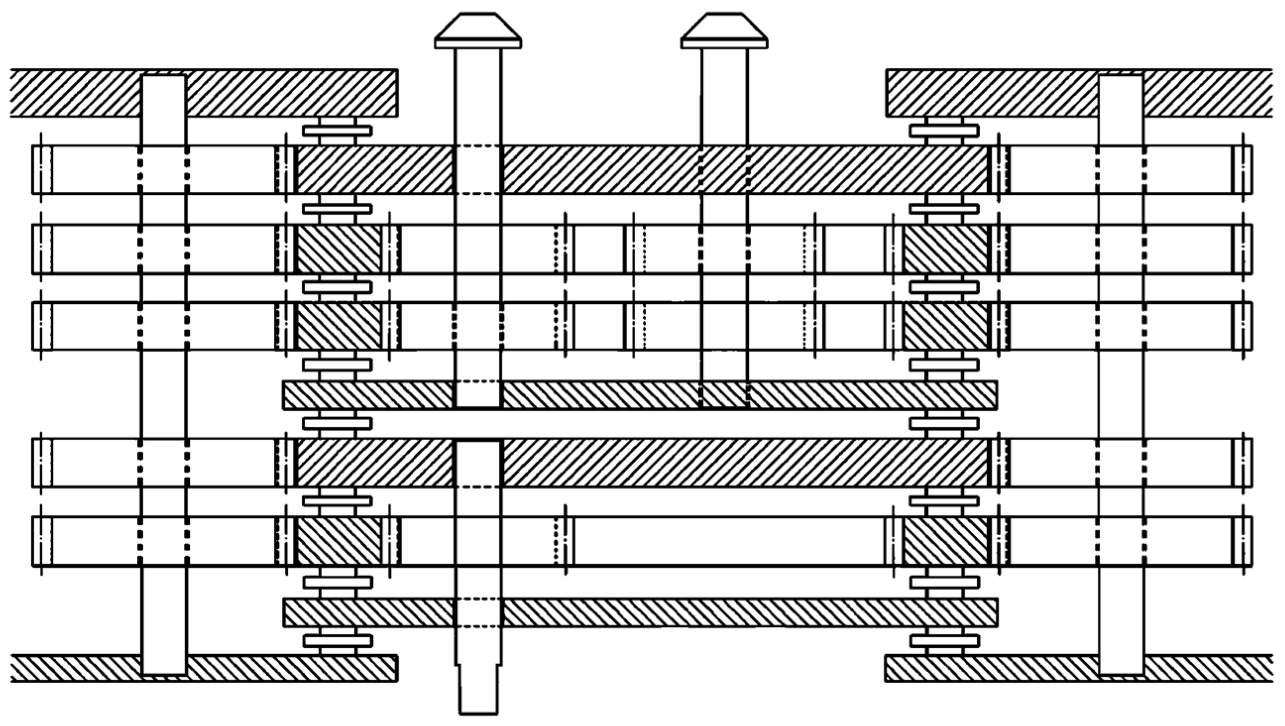
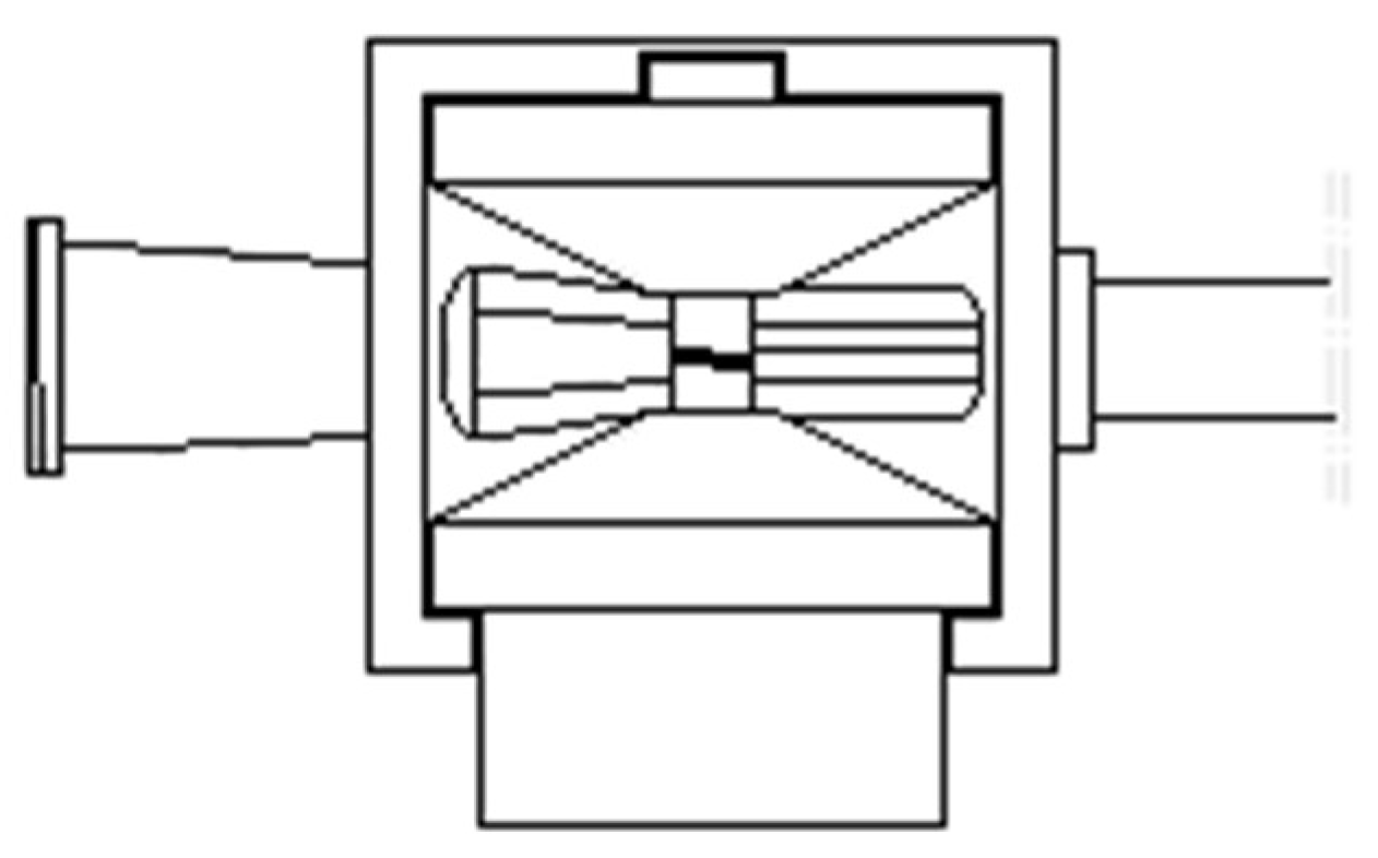
Before discussing the new disposables, a new double RA was also studied, presented in
Figure 14, which shows the internal gearing in the section of this new RA [
31], presenting two gear trains aligned on the same axis each with a mother gear and a frame fixed to its mother gear, and three hollow gears, two in the distal gear train (upper in the picture) and only one in the proximal (lower), with the control shafts coming out of the two gear trains in opposite directions. The original idea was to use this to control the tip curvature of a special catheter, yet to be built, but this will also be very useful when positioned on the distal RA of the cart, even for positioning the first catheter during angioplasty procedures, which will be explained later on in this paper. Naturally, this requires the use of five motors rather than three, but this will cause an increase in thickness of the RA by 28 mm.
Furthermore, given the need to keep the passage sterile while changing the disposable, the front cover, which was separating the disposables from the light plastic cover of the RA to keep the entire ambient sterile, was modified, adding a closed channel that completely separated the inner mechanisms of the RA from the push–pull disposables, as seen in
Figure 15. On the other hand, the second cover on the back of the RA was modified to connect with the new front one.
As previously mentioned, the new Disposable for Endovascular for Big size Catheters, DEBC, must be made into two components. Firstly, one lower component, connected to the bevel gears exiting the front gear, while the second component contains the right upper friction wheels, which were initially developed for the ROSINA (Robotic System for INtubAtion) [
32], to separate doctors from patients during the introduction of the fiberscope to direct the introduction of the endotracheal cannula during COVID-19.
Figure 16 shows the new DEBC with the two components, in the process of assembly with the new front disk and assembled. The screw on the upper disposable is used to adjust the system to a catheter dimension, ranging from 3 to 20 French. The DEC has an identical shape (the B is missing because the catheter has relatively small size), but for the dimensions of the friction wheels and the DEGW (Guide Wires) will differ, only because the bevel gear is on the right.
From this structure will also derive the new DA (Disposable for Angioplasty), which has already been designed, even if not yet built, whose scheme is presented in
Figure 17 [
33]. On the left, there are again two friction wheels rotating in the same direction thanks to an idle gear interposed, as il the 7 mm disposable of
Figure 6, where the spur gears connecting the two friction wheels have the same number of teeth, but reducing the module, from 1 to 0.75 mm, while the two friction gears are surmounted by two small friction wheels belonging to the upper element. The portion dedicated to the guide wire is totally different, in which the two small upper friction wheels are substituted by a big friction wheel, while on the lower component, a first friction wheel fixed to the bevel gear is present, identical to the one for the catheter, but without the spur gear. Two more small friction wheels are positioned to come into contact with the big superior friction wheel. This arrangement has been made possible by the bigger dimensions of the passage hole. Moreover, since both the catheters and the guide wires are extremely small in size, as can be seen from the drawing, the 4 mm cannula, which keeps them straight before entering the hemostasis valve, is still present.
However, there is a second problem to solve. Initially, the catheter and guide were internal to each other; however, this is no longer true about 20 cm from the tip of the catheter. Hence, during the operation, these present different access points within the hemostatic valve. This causes, in the case of disposable rotation, the wrapping of the guide around the catheter, reducing its possibility of rotation. Therefore, it was hypothesized that we rotate the hemostatic valve to keep it in a fixed position with respect to the disposable. However, there is also the need to maintain both the fixed position of the initial catheter and that of the radio-opaque liquid tube. This entails the use of a special hemostatic valve, which will be mounted at the tip of the disposable, which will easily pass through thanks to the new dimensions of the passing hole, while its end portion must be blocked to prevent its rotation, using a support that was already present to keep the whole valve fixed, which will now only fix the terminal part. For this purpose, the valve first portion is fixed to the disposable, and the valve will open by pressing the internal tube towards the RA, free to move with respect to the main part of the disposable, guided by a kind of rail, whose necessity will be explained thereafter. Please note the presence of a joint that allows the relative rotation between the two elemeots 0f the hemostasic valve.
In fact, the rotating hemostatic valve could be used, before the angioplasty procedure, for a guide with a movable core to position the initial catheter. We then decided to detach the passage tube of the guides and catheters and relative hemostasis valve from the DA using a cross graft kind of rail. This allows the insertion and removal of it from the DA in the fixed position, so that the two parts can rotate together, indicating its presence under the central tube with dashed lines.
Previously, the possibility of adding a new parallel RA was considered to cope with the problem of the possible presence of a coronary branch near a stenosis, which could close the branch while inflating the balloon. In this case, we considered adding the new RA in a parallel position, installing a new disposable and relative hemostasis valve (which had to be present from the start using an appropriate Y connector to connect the two hemostasis valves to the initial catheter), in order to introduce a new guide wire to enter the branch before inflating. It was a good solution, but very cumbersome and possibly expensive. On the contrary, given the bigger size of the new disposable (but always a portion of the size of CorPath disposables), an open channel was left between the friction wheels of the catheter and guide wire, in which the guide wire inside the catheter may be positioned, a new guide wire may be introduced and inserted into the branch, and the catheter positioned and inflated, using only one disposable and one RA.
Naturally, since guide wires that have a movable core exist, these may be very useful for endovascular surgery, while each RA already controls three degrees of freedom. The software of the console unit was easily modified to control the movable core of these wires. For angioplasty, the console was controlled with the joystick on the left, used for the advancement/retrieval of the catheters, and with the joystick on the right, used for the advancement/retrieval of the guide wire and rotation of both. Thus, it was necessary to modify the software to drive two RA, each with a single joystick, also commanding catheter rotation with the left joystick on a first RA and adding the rotation of the body of the right joystick to control guide core motion on the second RA.
This problem was already solved for the disposables initially designed for the 7 mm passage, using the portion dedicated to guide wires, again modifying the friction wheels to cope with a larger guide wire. Additionally, in order to move the new DEGWMC Disposable for Endovascular for Guide Wires with Movable Core) using the command for advancing the catheters, the friction wheels for the catheter were eliminated, replacing them with three spur gears, placed with axes whose positions were determined in order to allow a rack placed on top to mesh with both upper gears. Then the head of the guide wire core will be inserted in a hole through the rack and secured with a screw, while the body will be clamped externally. This is shown in
Figure 18a, on the left, and is valid for movable cores welded on the tip, to straighten the initial curve. A further alternative was for the case in which the movable core was free to move inside the guide wire, in which the allowed motion was much longer than in the previous case. This time, rather than coupling a spur gear and a rack, a rather big wheel was added externally to wrap around the metallic core, keeping it guided in the case of inversion of the motion. This disposable is presented in
Figure 18b, on the right.
For this second disposable, it should be noted that this is very useful when one has to introduce pre-curved catheters, which can be straightened by pushing the core ahead and turning the catheter to negotiate the various deviations needed. However, once the final position is reached, the guide wire is to be pulled away, while the catheter cannot be turned anymore. For this application, is very useful to use the double RA previously described, since it allows the hemostasis valve, fixed to the pre-curved catheter, to rotate what is needed to allow the catheter to reach the point of interest, and from this point onwards, it blocks the motion of the second gear train, while having full control of the first train gear.
This could be useful for angioplasty, noting however that, in this case, the hemostasis valve used by the DEGWMC should be the valve used by the angioplasty, which should be mounted on the initial disposable for the guide wires. Then, the disposable should be removed leaving in place the rotating valve, on which the angioplasty disposable would be connected. For this reason,
Figure 18b illustrates the presence of the same dashed lines below the tube, which are present in the disposable for angioplasty.
Once the 7 mm components and the modified software of the console were produced, a trip to Rome was organized and in vitro experiments were started with the Gemelli partners. To do so, it was necessary to develop a catheter with controllable tip curvature, both manual and via console. The solution for the manual case was rather simple, using a two lumen catheter, with a primary lumen of 3 French and a 1.5 French on the side, a series of wedge-shaped cuts on the side of the smaller lumen and a wire fixed on the tip, and pulled by a drum ratchet controlled near the connector. However, if one wanted to control the curvature from the proximal RA, the one controlling the catheter, it was necessary to provide a kind of sock that would cover the catheter as this was penetrating the patient’s vases, in order to impede the wire controlling the tip curvature from damaging the vases when pulled, since it was impossible to leave the controlling wire inside the catheter. A solution was found, but it was too difficult and expensive to realize. Hence, a second solution was found using the cart, causing the first idea of the double RA previously illustrated, which, during catheter penetration, must follow the catheter advancement. Thus, using the double RA, the proximal RA and the proximal portion of the distal RA must turn in the same direction of the same amount, while the distal RA must approach the proximal RA at the speed at which the catheter is advanced. If a pre-curved catheter is used, the right joystick will command advancement and rotation of the guide wire, while turning the head of this joystick will actuate the guide wire core motion. When the catheter with the controlled tip curvature is used, this will be controlled by rotating the head of the left joystick, which commands the catheter.
Figure 19 shows a first possible scheme of the disposable to be placed in front of the double RA, fixed to the rotating second train gear, where 1 is the connector of the catheter containing the drum to pull the wire inside the catheter small lumen, 2 is the catheter, 3 is the hemostasis valve, 4 is the shaft coming from the RA to actuate the catheter tip, 5 is the splined bushing to connect and lock the shaft coming from the RA, 6 is the pair of bevel gears that allow the rotation of the drum and 7 is a semi-funnel which drives the guide wire into the hemostasis valve.
Figure 20 shows the connector with the drum to be turned by the splined bushing connected to the RA, where the wire winds on the central part of small diameter, and
Figure 21 shows the two-lumen catheter, presenting a series of wedge-shaped cuts on the small lumen side, in which the wire fixed on the tip runs [
34].
4. Discussion
A first complete series of disposables and relative accessories has been developed or at least designed for almost all surgical endovascular interventions and the in vitro experiments and patient trials, at least as far as angioplasty is concerned, seem to demonstrate that the results are more than satisfactory, even if it will be necessary to build more new versions for the new RA, which change in dimensions but not in principle. The only new disposable to be defined in every detail is the controlled tip one, while the opto-haptic system to measure forces will be built as described previously.
However, there are a good number of observations to be made. For instance, when using angioplasty with the initial catheter fixed in front of the proximal RA, the force meter will only be sensible to the forces exerted by the patient’s body after the exit from the initial catheter. This is because friction between the initial catheter and catheter and guide wires before the exit from the catheter is compensated, as the initial catheter is fixed to the hemostasis valve, which is fixed to the RA, and hence these forces are internal to the system and not detectable. However, what is interesting is exactly what happens in the coronaries, not elsewhere. This is impossible with the CorPath which, with an expensive disposable, measures the entire force opposed to advancement, including the irrelevant part of it.
Another fact is that ROSES disposables are very small and relatively simple, while the rest of the system can be covered by cheap sterile plastic or re-washable cloth, and can be fitted with the useful disposable in every RA, and possibly on two sides of it, looking at the sketch of
Figure 13. Moreover, it is also possible to place three RAs in series, of which the intermediate will be a double RA. This will probably be necessary for carotid of brain surgery, using an initial catheter either pre-curved or with controlled tip curvature. Then, the intermediate RA will push the suitable thin catheter while advancing the introduction of the initial catheter, and the third RA will push the guide wire inside the thin catheter. This is because, for these interventions, the guide wire is always moving inside the catheter or advancing alone, but never in parallel to it as in angioplasty.
Using two double RAs and a standard one as a proximal, the system could control 5 independent rotations and 12 advancements, for a total of 17 parameters controlled (two per simple RA, four per double RA, plus the advancements of the second and third RA). In fact, this will hardly ever be necessary.
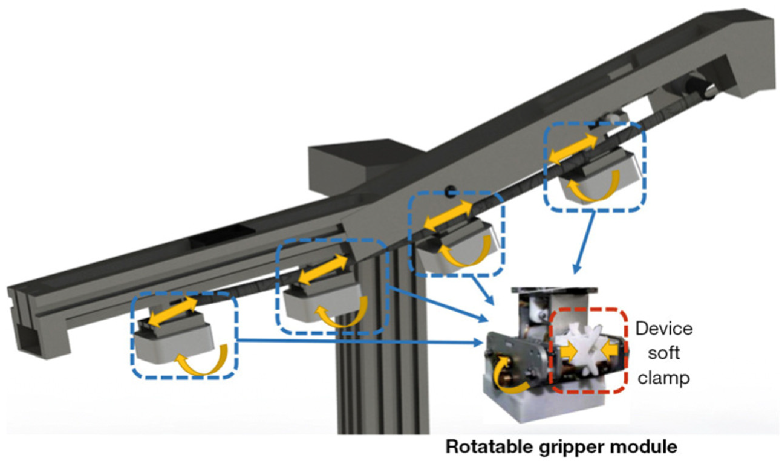
This is even more than the 12 degrees of freedom exhibited in the article by Zhao et al. [
8], describing the work of Prof. Wang [
9], from which
Figure 22 is taken. In fact, the Chinese system uses linear translation to move the four control units rather than friction wheels, and this increases the dimensions of a system with four independent controllers as reported by the paper quoted, which concludes that this system is too big to fit in an operatory room. In ROSES instead, the system has only a maximum of two advancements controlled by a worm screw, the first RA being in a fixed position, all-remaining degrees of freedom being produced by friction wheels or rotating gear trains, resulting in a system with limited encumbrance that definitely fits in a surgical room.
EC mark application is needed for the entire system, while the final disposables will be developed via injection molding since 3D printing, even if irreplaceable during the experimental phase, is too slow for the final market, hardly sufficient for a few sales to friends.
As far as patents are concerned, during the development of this work, several patents were presented, which are listed in the references.

 ,
, 


