Article

Impingement During Dislocation-Prone Activities: Geometric Modeling Analysis of an Uncemented Standard Versus Modular Dual Mobility Acetabular Cups

1
Institute of Medical and Biological Engineering, University of Leeds, Leeds LS2 9JT, UK
2
Johnson & Johnson MedTech UK, Leeds LS11 8DT, UK
3
Wrightington Wigan and Leigh NHS Foundation Trust, Wigan WN1 1XX, UK
*
Author to whom correspondence should be addressed.
Prosthesis 2025, 7(3), 59; https://doi.org/10.3390/prosthesis7030059
Submission received: 3 April 2025 / Revised: 20 May 2025 / Accepted: 23 May 2025 / Published: 27 May 2025
(This article belongs to the Special Issue State of Art in Hip, Knee and Shoulder Replacement (Volume 2))

Abstract

Background/Objectives: The stability of dual mobility (DM) total hip arthroplasty (THA) is often attributed to reduced impingement incidence and a superior range of motion (ROM) compared to the corresponding values when standard implants are used. However, few studies have directly explored this. Thus, the purpose of the present study was to compare the incidence of impingement and the range of motion between standard and DM acetabular cups, whose diameters are suited to the same patient anatomy. Methods: One standard and two DM implants were virtually implanted into a pelvis using a previously developed geometric model. Joint motions, which were representative of seven dislocation-prone activities of daily living (ADLs), as well as walking, were applied to each device type at a range of cup orientations (inclination/anteversion). Conclusions: There were no placement positions that avoided impingement across all seven ADLs, regardless of cup construct type. A similar impingement incidence and ROM were observed for standard and DM constructs, although the consequences of impingement are potentially more serious for DM devices (metal–metal contact) than for standard constructs (metal–polyethylene contact). This finding contradicts the common notion that DM-THAs have a reduced impingement incidence and superior ROM, instead suggesting that their stability may be attributed to alternative mechanisms, such as increased jump distance.

Graphical Abstract

1. Introduction

Dislocation is the leading cause of early (<1 year) aseptic revision for total hip arthroplasty (THA), accounting for over 20% of early failures in the United States [1,2]. Dislocation is defined as a complete and permanent loss of contact between the bearing surfaces, as opposed to subluxation, which is partial and temporary. Dislocation may be influenced by several factors relating to the patient (e.g., soft tissue tension and patient activities), the implants (e.g., range of motion and head–neck ratio), and the surgical process (e.g., component orientation). A known risk factor for dislocation is impingement, i.e., the presence of abnormal contact between the bony and prosthetic interfaces, which provides the femoral head with a mechanism to lever out and potentially subluxate or dislocate. The posterior dislocation (anterior impingement) of the head is the most common mode of hip dislocation, which can occur during activities such as sitting or squatting [3,4].
Revisions that are secondary to dislocation are associated with poorer patient outcomes and pose a significant economic burden to healthcare systems [5]. Several acetabular components have been deployed to reduce the incidence of dislocation, including dual mobility (DM) constructs. DM-THAs feature an unconstrained polyethylene liner, which encapsulates the femoral head and freely rotates, thus forming a secondary articulating surface between the liner and the shell. By mobilizing the liner, the effective head size of the DM bearings is increased when compared to standard (unipolar) implants, therefore increasing the construct’s jump distance and overall stability. Several reports suggest that DM-THAs also offer a greater range of motion (ROM) in relation to impingement in comparison to standard implants [6,7]. However, this topic has not been well explored through comparative analyses, and it is not clear whether DM implants truly offer a superior range of motion relative to standard devices when both are dimensionally suited to the same patient anatomy.
The usage of DM-THAs has been steadily increasing in primary, trauma, and revision settings across the globe [1,2,8]. In the United States, DM constructs are utilized in 7.5% and 17.9% of all primary and revision procedures, respectively, and account for over one-third of revisions indicated for dislocation [2]. Although some reports suggest DM-THAs have promising survivorship rates and a reduced incidence of dislocation [9,10], recently published joint registry data and large-cohort clinical studies paint a more mixed picture, with similar aseptic revision and dislocation rates being identified between standard and DM devices [2,11,12]. This may explain the recent emergence of large-diameter (≥40 mm) constructs and the steady decline in the number of DM-THAs in the United States since 2021 [2]. However, clinical outcomes may be confounded by patient selection, and dislocations successfully treated with closed reduction are not always captured in clinical reports, which often use revision as the only metric to measure implant failure. Due to these conflicting reports, the survivorship and stability of DM-THAs compared to standard implants are uncertain.
The purpose of the present study was to use geometric modeling to compare the impingement incidence and ROM of modular DM and standard acetabular cups for uncemented total hip arthroplasty, with the outside diameter of each cup being suited to the same patient pelvic anatomy. To this end, each of the cups was subjected to a series of joint motions that arise from typical activities of daily living; additionally, a wide range of cup orientations were used, including those which are clinically relevant.

2. Materials and Methods
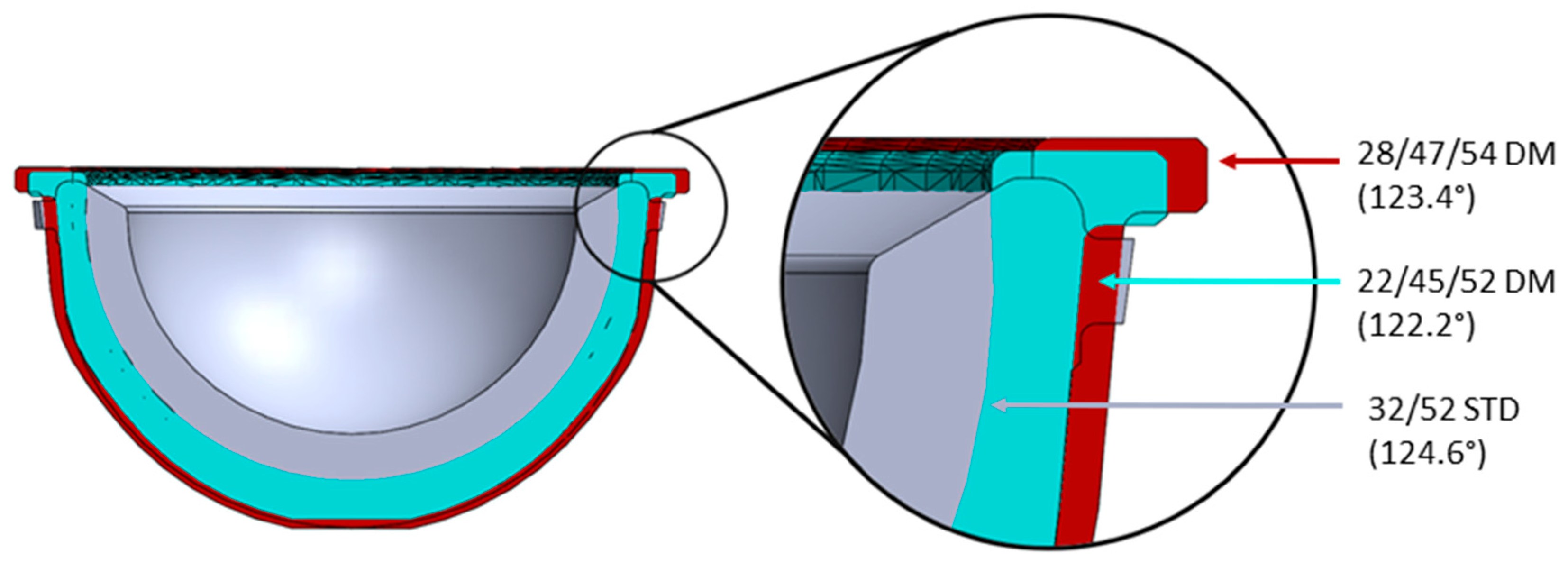
2.1. Components

Components based on the geometries of the Pinnacle® THA system (DePuy Synthes; Raynham, MA, USA) were modeled using a commercially available computer-aided design (CAD) software package (SOLIDWORKS 2022; Waltham, MA, USA). Three uncemented acetabular cup combinations, including one standard and two modular DM devices, were considered, which were dimensionally suited for the same size of acetabulum (Figure 1). The standard implant featured a 52 mm outer diameter (OD) shell, a 32 mm inner diameter (ID) neutral polyethylene liner, and a 32 mm OD femoral head (32/52STD). The DM implants comprised the following: (a) a 52 mm OD modular shell with a 45 mm ID metal liner insert, a 45 mm OD/22 mm ID polyethylene mobile bearing, and a 22 mm OD femoral head (22/45/52DM); and (b) a 54 mm OD modular shell with a 47 mm ID metal liner insert, a 47 mm OD/28 mm ID polyethylene mobile bearing, and a 28 mm OD femoral head (28/47/54DM). All components were paired with a collarless Corail® size 12 femoral stem.

2.2. Geometric Modeling

The components were virtually implanted into a previously developed CAD model of a hemi-pelvis and femur of a male subject [13]. The femoral stem was positioned to conform with the native geometry (i.e., the alignment of the femoral stem axis with the axis of the native femur), and the prosthetic head was aligned to the center of the native head. After the virtual reaming of the acetabulum to produce a hemisphere, the pelvis and femur were then scaled to allow for the implantation of the 52 mm OD acetabular shells and associated polyethylene liner (32/52STD) or metal liner insert (22/45/52DM). Further reaming allowed for the implantation of the 54 mm OD acetabular shell with the metal insert (28/47/54DM). The DM constructs were fitted with the appropriate mobile bearing, with its front face being parallel to that of the metal liner. Femoral heads were then added. Correct component positioning was confirmed by an experienced orthopedic surgeon.
Joint motions were applied to the model using kinematic data that had previously been reported for seven dislocation-prone activities of daily living (ADLs), as shown in Figure 2 [14]. Five of the ADLs were posterior-dislocation (or anterior-impingement)-prone activities, which included bending to reach an object on the floor while standing (STOOP), sit-to-stand from a low seat (SSL), sit-to-stand from a normal-height chair (SSN), leg crossing while seated (XLG), and shoe tying while seated (TIE). The final two ADLs were anterior-dislocation (or posterior-impingement)-prone activities, which included rotating the upper body away while standing (PIVOT), as well as rolling over while in a supine position (ROLL). These data were defined as the position of the femur relative to the pelvis and therefore included motions of the pelvis during each activity. Joint motion that was representative of a walking cycle (Figure 2) was also applied to the model, which was derived from international testing standards for THA devices [15]. Joint motions were applied to the model as angular displacements relative to the femoral head center through three axes of motion—flexion (+)/extension (−), abduction (+)/adduction (−), and internal (+)/external (−) rotation.
The model ran until either an impingement event occurred, at which point the motion would cease and the type of impingement was determined and recorded, or until the activity profile was complete. Impingement was identified using the “Interference Detection” function in the CAD software package, which determined when overlap occurred in the model and has previously been shown to detect low volumes (>1 mm3) of interference [13]. For each device type, the incidence of implant–implant, bone–bone, and implant–bone impingement was assessed for each ADL (including walking) across a clinically relevant range of acetabular cup inclination (30–70°) and anteversion (0–50°) angles in 5° increments.
It should be noted that impingement events vary between standard (unipolar) and DM constructs. For the purposes of this study, the impingement of a standard construct was defined as a single, immoveable stop, which involves contact between the femoral neck and either the polyethylene liner or bone. However, in DM constructs, contact first occurs between the femoral neck and the mobile polyethylene bearing, which is referred to as femoral neck–mobile bearing contact in this study. Once engaged, the combined construct moves to allow for further rotation; it is at this stage that impingement may occur between the femoral neck and either the rim of the metal liner or the bone (Figure 3). This study investigated femoral neck–mobile liner contact for the DM implants, as well as impingement for all three constructs.
For each combination of construct, contact mode, and activity, a results matrix was produced in an 11 × 9 format of inclination versus anteversion. To condense the ADL results, summary matrices for each construct and contact mode pairing were produced and compared. For each shell orientation, a number was assigned to the matrix based on the number of ADLs for which a contact event of any sort occurred, ranging from zero (no contact during any ADL) to seven (contact occurred in all seven ADLs). A heatmap was applied to the resulting matrix to aid in the visualization of the data. Of interest, each matrix had a shaded area representing the manufacturers’ instructions for implantation (inclination 40–45°; anteversion 15–20°) and a broadened box for a more likely range (inclination 35–50°; anteversion 10–25°), highlighting clinically relevant implantation angles. The total number of impingement events within the shaded area was obtained for each of the three constructs.
Simple ROM-to-impingement calculations were also made for each construct. These were calculated in one plane across the thinnest axis of the femoral neck in order to provide a theoretical maximum ROM for each device type, whereby no bony or soft tissue constraints exist.

3. Results

The data associated with this paper are openly available from the University of Leeds Data Repository [16].

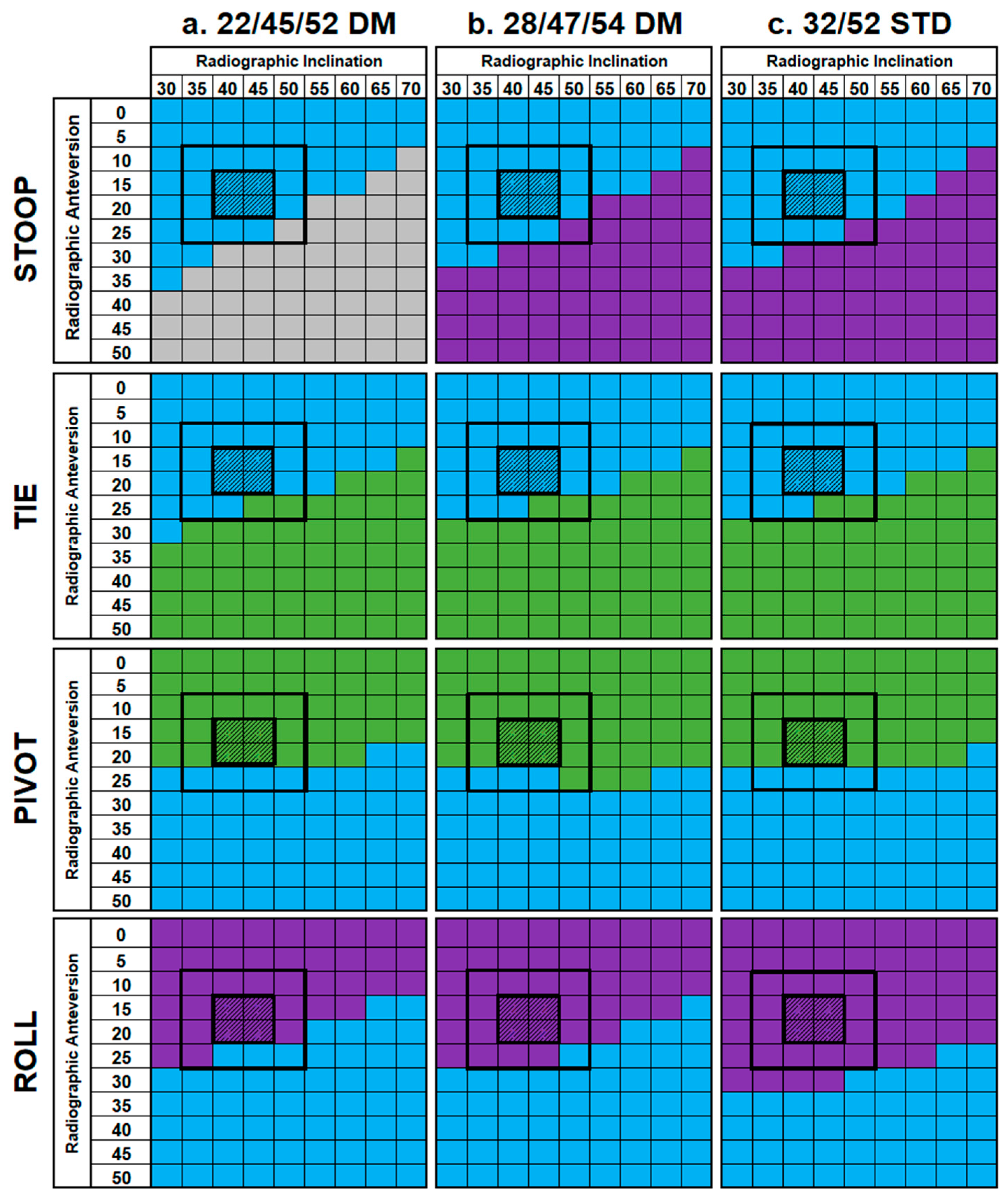
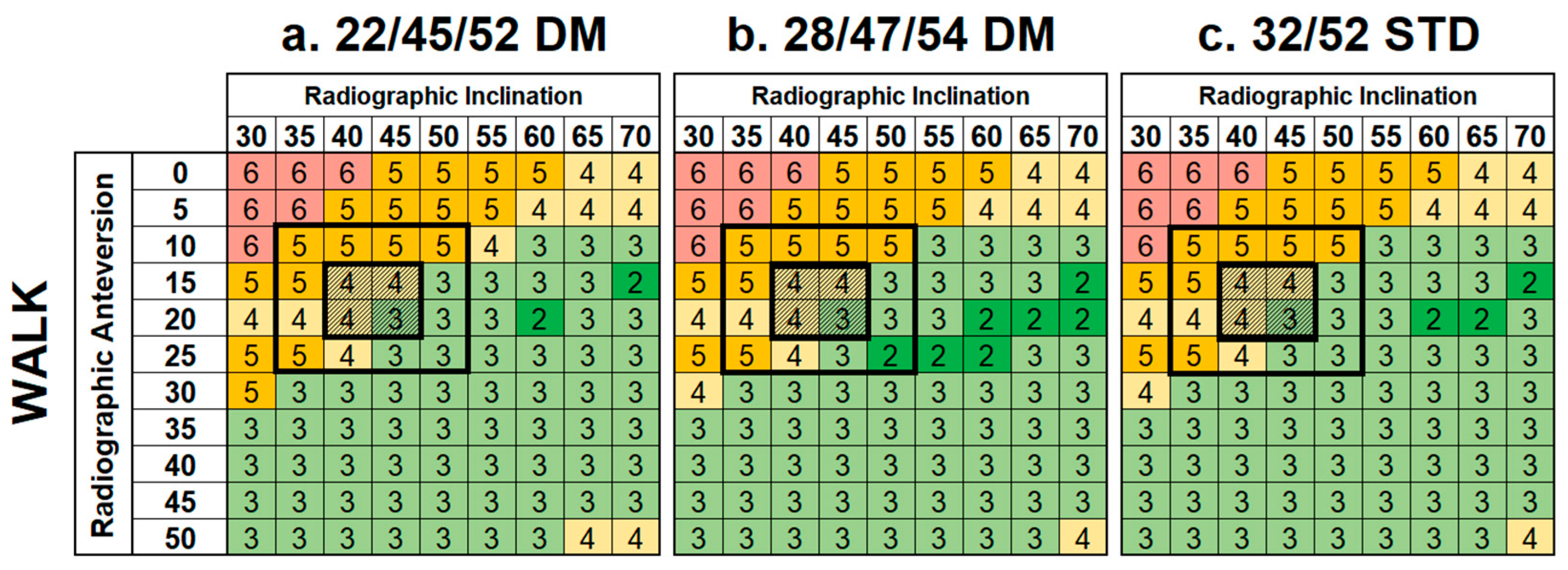
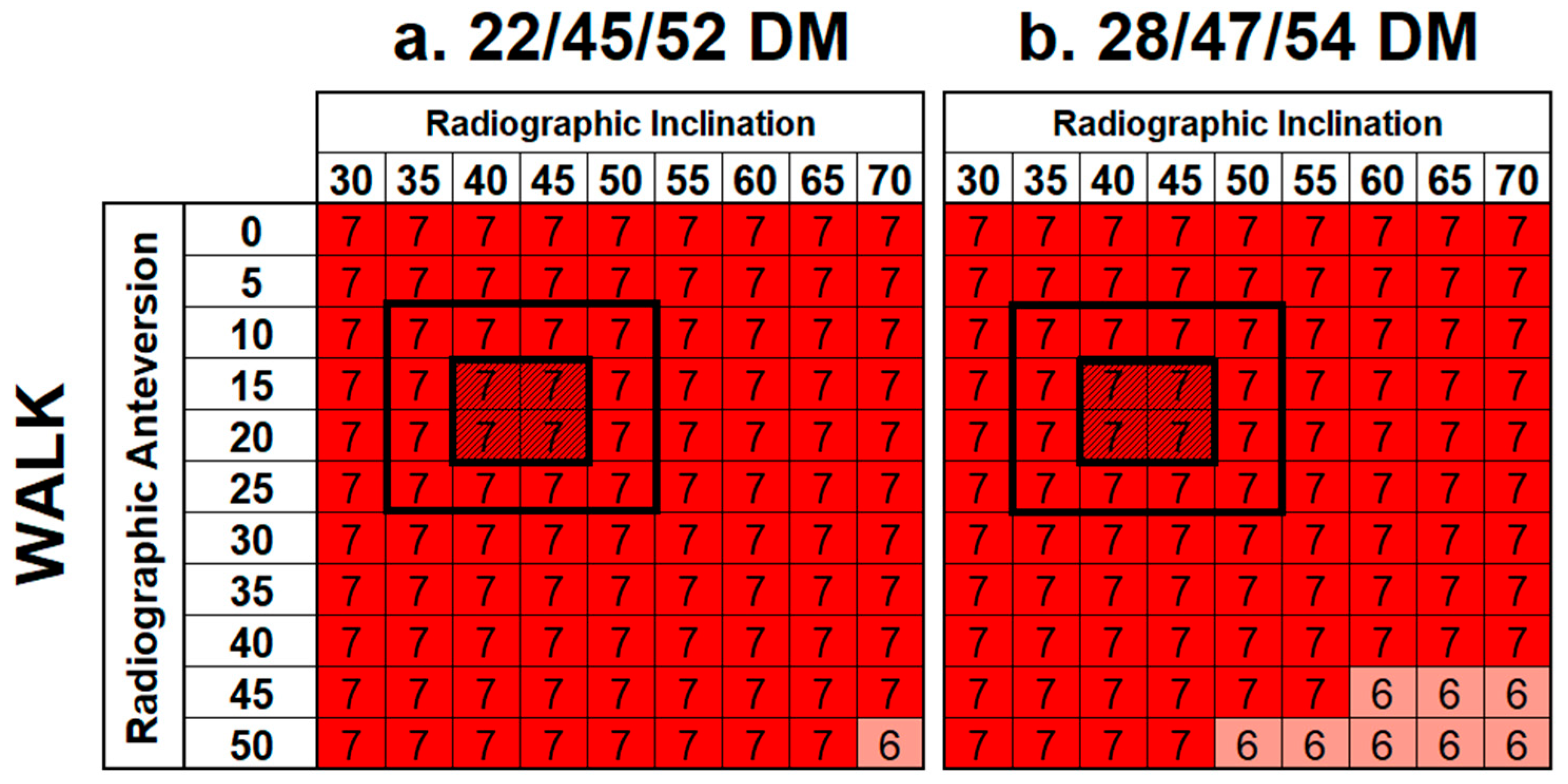
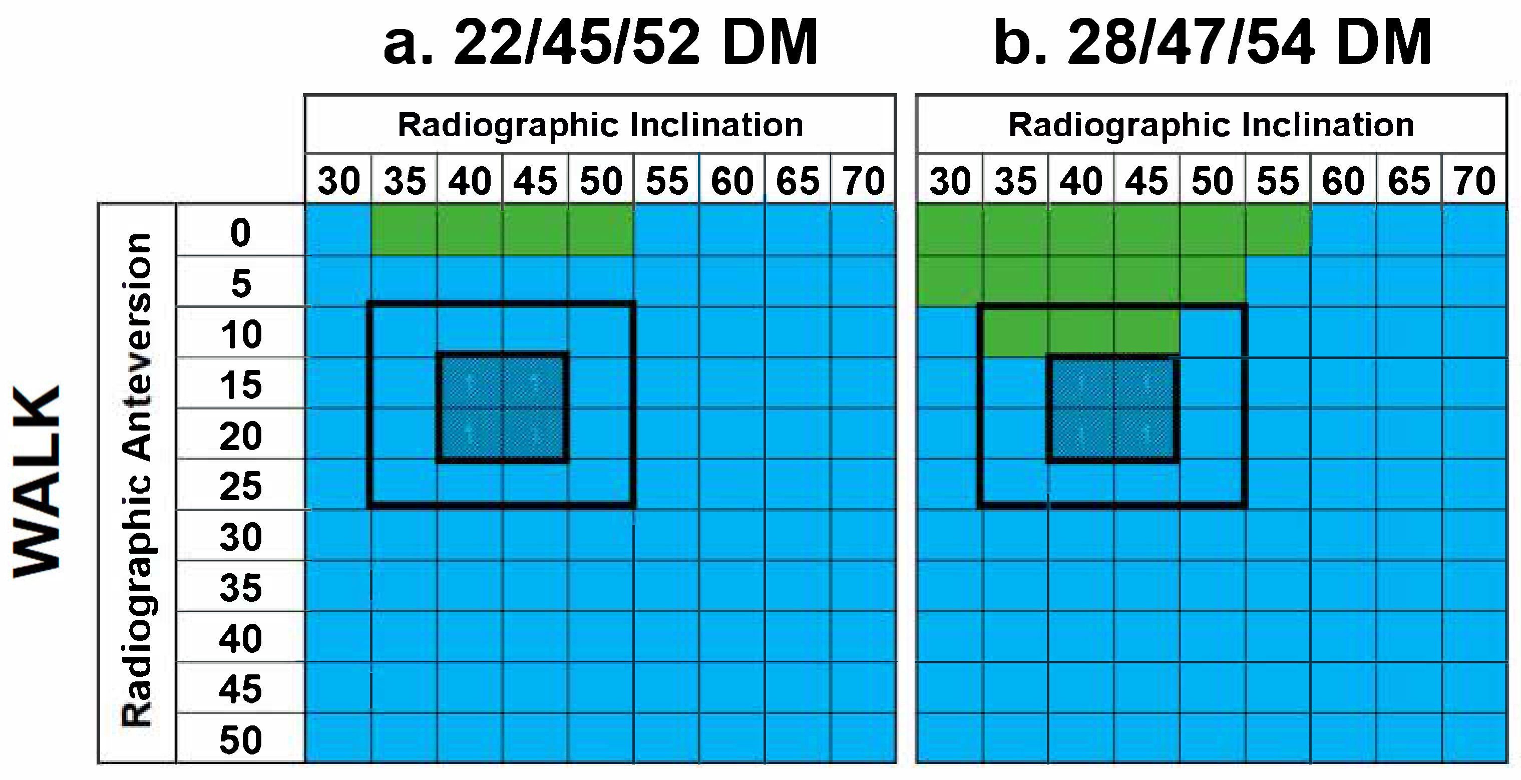
3.1. Incidence of Impingement in Constructs

A total of 2376 cases were investigated, yielding 24 results matrices [16]. Examples for four activities are shown in Figure 4.
The same general patterns of impingement were observed across all three constructs during each activity. For the ADLs at risk of posterior dislocation (SSL, SSN, TIE, XLG, and STOOP), four followed a similar pattern as was typified by TIE in Figure 3, whereby implant–implant impingement was observed at the lower ranges of inclination and anteversion, yielding no impingement as these ranges increased. The exception to this trend was STOOP, whereby no impingement-free shell orientations were identified in any construct design. Instead, implant–implant impingement was observed at lower inclination and anteversion angles, which changed to either bone–bone impingement (32/52STD, 28/47/54DM) or implant–bone (22/45/54DM) impingement as these increased.
The two ADLs associated with anterior dislocation (PIVOT and ROLL) had different effects. PIVOT was generally impingement-free until the anteversion angle was increased beyond 20°, in which case implant–implant impingement occurred. Alternatively, ROLL had no impingement-free shell orientations and instead resulted in either bone–bone or implant–implant impingement depending on component placement.
The application of standard gait to the constructs (Figure 5) indicated that impingement only occurred during a small number of shell orientations with extreme anteversion angles that are not clinically relevant (≥40°).
Of note, four activities (SSL, XLG, PIVOT, and walking) did not produce impingement across the majority of clinically relevant shell orientations. However, this was not the case for the remaining four activities (SSN, TIE, STOOP, and ROLL).
The summary matrices (Figure 6) show that there were no shell orientations that avoided impingement across all ADLs, either for the standard or DM constructs. All implants had a broad range of shell orientations, whereby impingement only occurred in two or three ADLs (typically STOOP, PIVOT, and ROLL). However, the impingement incidence was as high as five when considering only the clinically relevant shell orientations (i.e., within the marked 4 × 4 boxes of the summary matrices). Interestingly, the color gradients across all three summary matrices were comparable with no visually discernible differences in their trends or patterns. Additionally, the sum of impingement incidents within the clinically relevant range of shell orientations was about the same for all three constructs (range: 64 to 65).

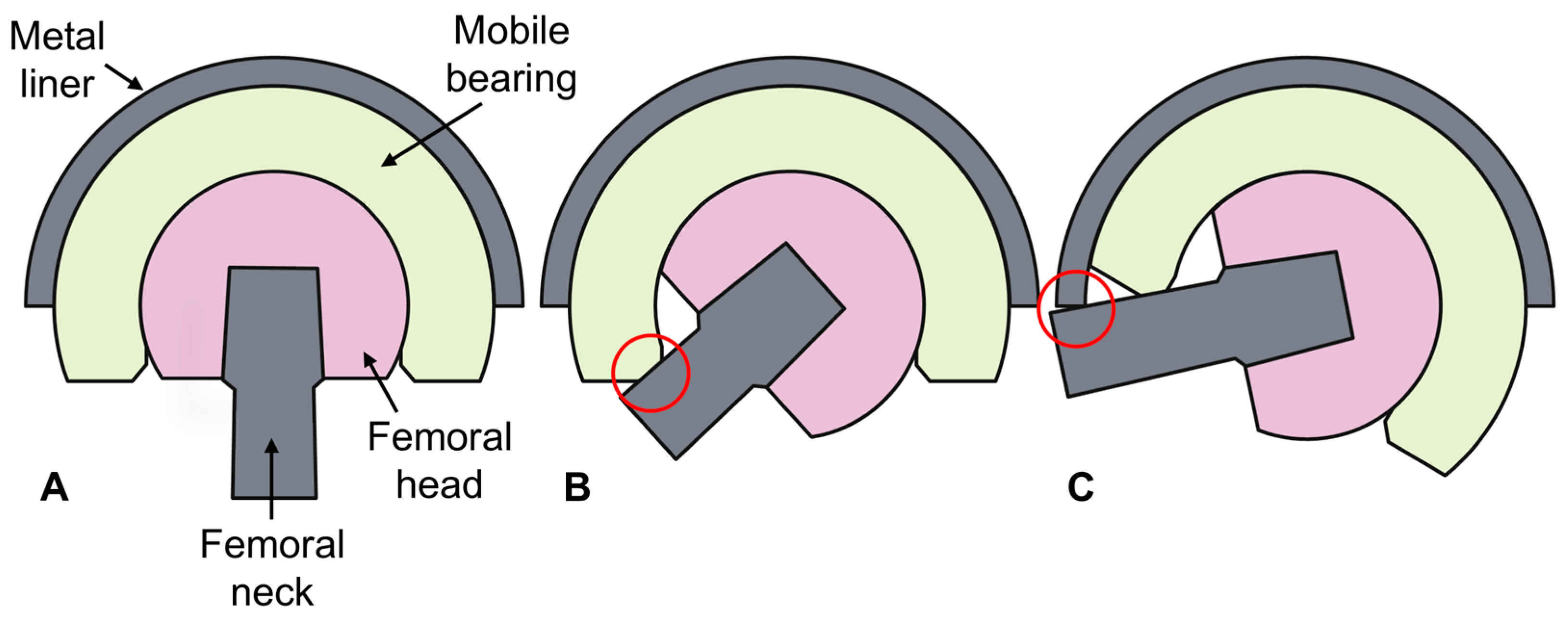
3.2. Incidence of Femoral Neck–Mobile Bearing Contact in DM Cups

A total of 1584 cases were investigated, yielding 16 results matrices [16]. Summary matrices for DM femoral neck–mobile bearing contact are shown in Figure 7. For both DM constructs, neck–mobile bearing contact occurred during all activities and shell orientations, with the exception of XLG, at high inclination and anteversion angles. Similarly, femoral neck–mobile bearing contact occurred with most shell orientations during walking (Figure 8), except in some low-anteversion orientations.

3.3. Range of Motion of Constructs

Comparable ROMs to impingement of 124.6°, 122.2°, and 123.4° were obtained for the 32/52STD, 22/45/52DM, and 28/47/54DM constructs, respectively.

4. Discussion

This study investigated the incidence of impingement in both uncemented standard and modular DM constructs across a series of ADLs and shell orientations. The components included in this study were dimensionally suited to the same patient, with the aim of encapsulating the decisions a clinician might face when selecting the optimal implant for a patient. After reaming, the acetabulum was scaled for an ideal shell size of 52 mm. If a standard component was used, the clinician would likely opt for a 32 mm diameter femoral head, hence the inclusion of the first construct option (32/52STD). If a DM device was deemed necessary, a 52 mm acetabulum would only accommodate the 22/45/52DM device, hence the inclusion of the second construct option. The slight over-reaming of the acetabulum to 54 mm was considered to allow for a larger head size of 28 mm, hence the inclusion of the third and final construct option (28/47/54DM). This study investigated a broad range of inclination (30–70°) and anteversion (0–50°) angles, which are in line with reported clinical evidence [17,18].
This study found no practical component positions that avoided impingement across all dislocation-prone ADLs investigated in this analysis, regardless of device type. As shown in Figure 5, a lower incidence of impingement was observed as inclination and anteversion angles were increased above ≥45° and ≥20°, respectively, which agrees with previous recommendations derived from clinical experience [19,20]. However, it is important to note that this study considered impingement in isolation and did not account for other factors that may be consequential effects of increasing shell inclination/anteversion angles. For example, the excessive inclination of the acetabular component (>50°) is known to increase the risk of edge loading and accelerate wear [21]. These conflicting requirements emphasize the need to consider multiple factors when optimizing component placement.
This study also indicated that neck–mobile bearing contact in DM devices was likely to occur during walking and all investigated ADLs, regardless of shell orientation. This implies that the secondary articulation of DM constructs, between the mobile liner and the metal insert, becomes engaged during these activities, at least initially, when the liner is neutrally positioned. This is consistent with DM philosophy that suggests that these implants are likely to engage the outer bearing at greater ROMs. This finding also supports the known relevance of using stems with polished femoral necks in combination with DM cups to reduce potential wear generation at this interface, which may lead to intra-prosthetic dislocation [22,23].
Most notably, this study identified a similar incidence of impingement between the standard and modular DM constructs included in this analysis. This may be explained by the similar ROM between the implants, which becomes clear when the cross sections are examined, as shown in Figure 9. Although DM constructs have a larger effective head size, which would theoretically increase the ROM, the modular shells also have a marginally higher profile, which counteracts this effect. This highlights the fact that while monobloc DM devices may potentially offer a superior ROM relative to standard implants of the same outer diameter, this may not translate to modular DM constructs, especially in smaller sizes. Although a similar incidence of impingement was observed between the two construct types, it is important to consider how their outcomes may differ. The most common impingement interface identified in this study was implant–implant, which results in contact between the femoral stem (titanium alloy) and the liner (polyethylene) for standard devices. However, for DM devices, this would involve contact between the femoral stem (titanium alloy) and the metal liner (cobalt–chrome alloy), the effects of which are potentially more serious.
Although a similar incidence of impingement has been observed between standard and modular DM devices, this does not suggest that the stability of the implants is comparable. The modular DM constructs assessed in this study have larger effective head sizes (45 mm and 47 mm) than the standard construct (32 mm), therefore leading to an increased jump distance and overall stability.
This study benefits from the use of a geometric model, whereby a wide range of variables (3960 unique cases) was analyzed with fewer resources, a lower cost, and a reduced time compared to experimental tests or finite element models. This study focused on a limited set of ADLs, including five posterior dislocation-prone and two anterior dislocation-prone activities. This limits the summary tables (Figure 5) such that anterior dislocation-prone activities are not proportionally considered with respect to posterior dislocation-prone activities. However, in some respects, this ratio is justified as it is reflected in clinical outcomes, which report that posterior dislocation is more frequent [3,4].
Three limitations of this study should be acknowledged. First, the activities were only applied to one hip geometry and, therefore, results may change with different bony anatomies. However, the predominant source of impingement was implant–implant, which would be largely unaffected by bony anatomy, and the results were interpreted comparatively. Second, the ADL activity profiles were derived from several healthy subjects, thus giving no indication of the variability across a population [14]. However, the upper age range of the subjects (44 to 59) encompassed that expected in an uncemented THA population [1]. Furthermore, potential THA patients would likely have a reduced ROM and level of activity; therefore, it would be unethical to expose them to dislocation-prone activities. However, using healthy subjects potentially gave an indication of the aspirational level of the activity of post-THA patients. Third, the model focused solely on impingement and did not consider other factors, such as surrounding tissues, joint contact forces, joint stability, and implant damage secondary to impingement. As such, the results of this analysis should not be interpreted in isolation and, instead, should be used to assess the relative differences between devices. We have not modeled the instability of the joint, which is clearly important when deciding on component position; therefore, our findings cannot be used to guide implant placement. Despite these limitations, this methodology is a simplistic and effective tool that can be used to compare the likelihood of impingement in different THA constructs. In principle, the model could be applied to different bone geometries and input parameters to evaluate a wider range of clinical scenarios.

5. Conclusions

No shell orientations were identified that avoided impingement across all dislocation-prone ADLs investigated in this analysis, regardless of component type. A lower impingement incidence was observed as the shell was moved to higher inclination and anteversion angles, toward the upper limit of manufacturers’ recommendations. However, this does not consider other factors such as edge loading and component wear, which may occur as the cup angle increases, therefore highlighting that ideal component placement is a compromise.
Consistent with DM philosophy, femoral neck–mobile bearing contact occurred for all activities investigated, including walking, which suggests that the secondary bearing between the mobile liner and shell becomes engaged at least initially.
Finally, this study identified a similar incidence of impingement and ROM between one standard and two modular DM constructs, which were dimensionally suited to the same pelvic anatomy (i.e., they had a comparable shell OD). This highlights that the common notion that DM devices provide a superior ROM relative to standard implants may not apply in modular DM constructs, suggesting that their enhanced stability may be related to alternative mechanisms, such as increased jump distance. In addition, the consequences of impingement are potentially more serious for DM devices (metal–metal contact) than for standard constructs (metal–polyethylene contact). Further investigations are recommended to explore the relationships between DM constructs and the incidence and consequences of impingement, which may be facilitated through clinical studies, retrieval analyses, experimental studies, and computational studies.

Author Contributions

Conceptualization: S.P.W., J.A., R.W., T.B., S.W., and G.I; methodology: S.P.W.; software: M.S. and S.P.W.; formal analysis: M.S., S.P.W., and G.I.; investigation: M.S., S.P.W., and G.I.; resources: J.A. and S.W.; data curation: M.S. and S.P.W.; writing—original draft preparation: M.S. and G.I.; writing—review and editing: M.S., S.P.W., J.A., R.W., T.B., S.W., and G.I.; visualization: M.S.; supervision: J.A., R.W., T.B., S.W., and G.I.; project administration: S.W.; funding acquisition: S.W. All authors have read and agreed to the published version of the manuscript.

Funding

This work was supported in part by the Engineering and Physical Sciences Research Council [grant numbers EP/R003971/1 and EP/W003139/1]. Authors M.S., R.W., and S.W. are supported in part by the National Institute for Health and Care Research (NIHR), Leeds Biomedical Research Centre (BRC) (NIHR203331). The views expressed are of the authors and not necessarily those of the NHS, the NIHR, or the Department of Health and Social Care. For the purposes of open access, the author has applied a Creative Commons Attribution (CC BY) license to any author-accepted manuscript arising.

Institutional Review Board Statement

Not applicable.

Informed Consent Statement

Not applicable.

Data Availability Statement

The data associated with this paper are openly available from the University of Leeds Data Repository [16].

Acknowledgments

The authors would like to thank Johnson & Johnson MedTech UK for their provision of the CAD models used in the geometric model. Thanks also go to Gregory Pryce for his efforts in developing the original geometric model, which has since been adapted for use in this research project.

Conflicts of Interest

Author S.P.W. is a paid contractor for Johnson & Johnson MedTech UK. Author J.A. is an employee of and has stock or stock options in Johnson & Johnson MedTech UK. Author R.W. has received research funding from DePuy Synthes and is an Editorial Board Member of the Proceedings of the Institute of Mechanical Engineers, Part H: Journal of Engineering in Medicine. Author T.B. has received research funding from the National Institute of Health and Care Research (NIHR), the John Charnley Trust, and Symbios UK, as well as royalties or licenses from DePuy Synthes, consulting fees from DePuy Synthes and Symbios UK, and speaker honorarium from Ethicon. They are also named on a patent (planned, issued, or pending) with DePuy Synthes; have participated on the board for Beyond Compliance; have a leadership role with the British Hip Society and British Orthopaedic Association; and has stock or stock options with Eventum Orthopaedics. Author S.W. has received research funding from DePuy Synthes and holds a leadership position with the British Orthopaedic Research Society. Author G.I. is a committee member of the Orthopaedic Data Evaluation Panel (ODEP). The funders had no role in the design of the study; in the collection, analyses, or interpretation of data; in the writing of the manuscript; or in the decision to publish the results.

Abbreviations

The following abbreviations are used in this manuscript:
THATotal hip arthroplasty
DMDual mobility
CADComputer-aided design
ODOuter diameter
IDInner diameter
ADLActivity of daily living
ROMRange of motion

References

  1. National Joint Registry. 21st Annual Report 2024. 2024. Available online: www.njrcentre.org.uk (accessed on 11 March 2025).
  2. American Joint Replacement Registry. The Eleventh Annual Report of the AJRR on Hip and Knee Arthroplasty. 2024. Available online: https://www.aaos.org/registries/publications/ajrr-annual-report/ (accessed on 11 March 2025).
  3. Masaoka, T.; Yamamoto, K.; Shishido, T.; Katori, Y.; Mizoue, T.; Shirasu, H.; Nunoda, D. Study of hip joint dislocation after total hip arthroplasty. Int. Orthop. 2006, 30, 26–30. [Google Scholar] [CrossRef] [PubMed]
  4. Woolson, S.T.; Rahimtoola, Z.O. Risk Factors for Dislocation During the First 3 Months After Primary Total Hip Replacement. J. Arthroplast. 1999, 14, 6. [Google Scholar] [CrossRef] [PubMed]
  5. Galvain, T.; Mantel, J.; Kakade, O.; Board, T.N. Treatment patterns and clinical and economic burden of hip dislocation following primary total hip arthroplasty in England. Bone Joint J. 2022, 104, 811–819. [Google Scholar] [CrossRef] [PubMed]
  6. Laura, A.D.; Hothi, H.; Battisti, C.; Cerquiglini, A.; Henckel, J.; Skinner, J.; Hart, A. Wear of dual-mobility cups: A review article. Int. Orthop. 2017, 41, 625–633. [Google Scholar] [CrossRef] [PubMed]
  7. Scott, T.P.; Weitzler, L.; Salvatore, A.; Wright, T.M.; Westrich, G.H. A Retrieval Analysis of Impingement in Dual-Mobility Liners. J. Arthroplast. 2018, 33, 2660–2665. [Google Scholar] [CrossRef] [PubMed]
  8. W-Dahl, A.; Kärrholm, J.; Rogmark, C.; Nauclér, E.; Nåtman, J.; Bülow, E.; Arani, P.I.; Mohaddes, M.; Rolfson, O. The Swedish Arthroplasty Register Annual Report 2023; Swedish Arthroplasty Register: Gothenburg, Sweden, 2023; Available online: https://sar.registercentrum.se/ (accessed on 11 March 2025).
  9. Darrith, B.; Courtney, P.M.; Della Valle, C.J. Outcomes of dual mobility components in total hip arthroplasty: A systematic review of the literature. Bone Joint J. 2018, 100, 11–19. [Google Scholar] [CrossRef] [PubMed]
  10. Reina, N.; Pareek, A.; Krych, A.J.; Pagnano, M.W.; Berry, D.J.; Abdel, M.P. Dual-Mobility Constructs in Primary and Revision Total Hip Arthroplasty: A Systematic Review of Comparative Studies. J. Arthroplast. 2019, 34, 594–603. [Google Scholar] [CrossRef] [PubMed]
  11. Khatod, M.; Chan, P.H.; Prentice, H.A.; Fasig, B.H.; Paxton, E.W.; Reddy, N.C.; Kelly, M.P. Can Dual Mobility Cups Reduce Revision and Dislocation Risks? An Analysis of 107,528 Primary Total Hip Arthroplasties in the United States. J. Arthroplast. 2024, 39, 1279–1284. [Google Scholar] [CrossRef] [PubMed]
  12. Hoskins, W.; Bingham, R.; Dyer, C.; Rainbird, S.; Graves, S.E. A Comparison of Revision Rates for Dislocation and Aseptic Causes Between Dual Mobility and Large Femoral Head Bearings in Primary Total Hip Arthroplasty With Subanalysis by Acetabular Component Size: An Analysis of 106,163 Primary Total Hip Arthroplasties. J. Arthroplast. 2021, 36, 3233–3240. [Google Scholar] [CrossRef] [PubMed]
  13. Pryce, G.M.; Sabu, B.; Al-Hajjar, M.; Wilcox, R.K.; Thompson, J.; Isaac, G.H.; Board, T.; Williams, S. Impingement in total hip arthroplasty: A geometric model. Proc. Inst. Mech. Eng. H 2022, 236, 504–514. [Google Scholar] [CrossRef] [PubMed]
  14. Nadzadi, M.E.; Pedersen, D.R.; Yack, H.J.; Callaghan, J.J.; Brown, T.D. Kinematics, kinetics, and finite element analysis of commonplace maneuvers at risk for total hip dislocation. J. Biomech. 2003, 36, 577–591. [Google Scholar] [CrossRef] [PubMed]
  15. BS ISO 14242-1:2014+A1:2018; Implants for Surgery—Wear of Total Hip-Joint Prostheses (Part 1: Loading and Displacement Parameters for Wear-Testing Machines and Corresponding Environmental Conditions for Test). International Organization for Standardization: Geneva, Switzerland, 2018.
  16. Smeeton, M.; Williams, S.; Anderson, J.; Wilcox, R.; Board, T.; Williams, S.; Isaac, G. A Geometric Model of Impingement During Dislocation Prone Activities in Dual Mobility, Lipped Liner and Standard Acetabular Cups; [Dataset]; University of Leeds: Leeds, UK, 2024. [Google Scholar] [CrossRef]
  17. Rittmeister, M.; Callitsis, C. Factors influencing cup orientation in 500 consecutive total hip replacements. Clin. Orthop. Relat. Res. 2006, 445, 192–196. [Google Scholar] [CrossRef] [PubMed]
  18. Danoff, J.R.; Bobman, J.T.; Cunn, G.; Murtaugh, T.; Gorroochurn, P.; Geller, J.A.; Macaulay, W. Redefining the Acetabular Component Safe Zone for Posterior Approach Total Hip Arthroplasty. J. Arthroplast. 2016, 31, 506–511. [Google Scholar] [CrossRef]
  19. McCollum, D.E.; Gray, W.J. Dislocation after total hip arthroplasty. Causes and prevention. Clin. Orthop. Relat. Res. 1990, 261, 159–170. [Google Scholar] [CrossRef]
  20. Brown, T.D.; Callaghan, J.J. Impingement in total hip replacement: Mechanisms and consequences. Curr. Orthop. 2008, 22, 376–391. [Google Scholar] [CrossRef] [PubMed]
  21. Hua, X.; Li, J.; Jin, Z.; Fisher, J. The contact mechanics and occurrence of edge loading in modular metal-on-polyethylene total hip replacement during daily activities. Med. Eng. Phys. 2016, 38, 518–525. [Google Scholar] [CrossRef] [PubMed]
  22. Spece, H.; MacDonald, D.W.; Mont, M.A.; Lee, G.-C.; Kurtz, S.M. Fretting Corrosion and Polyethylene Damage Mechanisms in Modular Dual Mobility Total Hip Arthroplasty. In Beyond the Implant: Retrieval Analysis Methods for Implant Surveillance; ASTM International: West Conshoshocken, PA, USA, 2018; pp. 106–117. [Google Scholar] [CrossRef]
  23. Di Laura, A.; Hothi, H.S.; Henckel, J.; Cerquiglini, A.; Liow, M.H.L.; Kwon, Y.M.; Skinner, J.A.; Hart, A.J. Retrieval evidence of impingement at the third articulation in contemporary dual mobility cups for total hip arthroplasty. Int. Orthop. 2017, 41, 2495–2501. [Google Scholar] [CrossRef] [PubMed]
Figure 1. Schematic illustrating the three device types analyzed in this study—32/52STD, 22/45/52DM, and 28/47/54DM.
Prosthesis 07 00059 g001
Figure 2. Joint motions of each activity, which were applied to the geometric model in three planes of rotation.
Prosthesis 07 00059 g002
Figure 3. Dual mobility implant in a neutral orientation (A) and during the two types of contact interactions which can occur—femoral neck–mobile bearing contact (B) and impingement (C).
Prosthesis 07 00059 g003
Figure 4. Result matrices showing impingement for the standard and DM constructs during four activities—STOOP, TIE, PIVOT, and ROLL. Cells are colored based on the type of impingement which occurred—implant–implant (blue), implant–bone (gray), bone–bone (purple), or none (green). Each matrix has a shaded 2 × 2 box, which represents the manufacturer’s instructions for implantation, as well as a broadened, outlined 4 × 4 box, which represents a more likely range of implantation angles.
Prosthesis 07 00059 g004
Figure 5. Results matrices demonstrating the effects of a walking cycle on standard and DM constructs with regard to impingement. Cells are colored based on the type of impingement that occurred—implant–implant (blue) or none (green). No instances of implant-bone or bone-bone impingement were identified.
Prosthesis 07 00059 g005
Figure 6. Summary matrices demonstrating the frequency of impingement events across all ADLs for the standard and DM constructs. Cells are colored based on the number of impingement events that occurred across all seven ADLs investigated, ranging between 0, 1, and 2 (dark green), 3 (green), 4 (yellow), 5 (dark yellow), 6 (red), and 7 (dark red).
Prosthesis 07 00059 g006
Figure 7. Summary matrices demonstrating the frequency of femoral neck–mobile bearing contact events across all ADLs for the DM constructs. Cells are colored based on the number of contact events that occurred across all seven ADLs investigated, ranging between 0, 1, and 2 (dark green), 3 (green), 4 (yellow), 5 (dark yellow), 6 (red) and 7 (dark red).
Prosthesis 07 00059 g007
Figure 8. Results matrices demonstrating the effects of a walking cycle on DM constructs with regard to femoral neck–mobile bearing contact. Cells are colored based on the type of contact that occurred—implant–implant (blue) or none (green). No instances of implant-bone or bone-bone impingement were identified.
Prosthesis 07 00059 g008
Figure 9. Cross section of the 32/52STD Pinnacle polyethylene liner (gray) and the metal liner inserts for the 22/45/52DM (blue) and 28/47/54DM (red) constructs.
Prosthesis 07 00059 g009
Disclaimer/Publisher’s Note: The statements, opinions and data contained in all publications are solely those of the individual author(s) and contributor(s) and not of MDPI and/or the editor(s). MDPI and/or the editor(s) disclaim responsibility for any injury to people or property resulting from any ideas, methods, instructions or products referred to in the content.

