


Finite Element Analysis and Simulation of 316L Stainless Steel and Titanium Alloy for Orthopedic Hip and Knee Prosthetics

 ,
, 
Abstract
1. Introduction
1.1. 316L Stainless Steel
1.2. Titanium
1.3. Applications of Finite Element Method in Prosthesis
2. Models, Constitutive Relationships, and Parameter Selection
2.1. Criteria for the Selection of Biomaterials
2.2. Biocompatibility and Host Response
2.3. Bone’s Biomechanical Characteristics
3. Finite Element Analysis
4. Analysis and Discussion
5. Conclusions
Author Contributions
Funding
Institutional Review Board Statement
Informed Consent Statement
Data Availability Statement
Conflicts of Interest
References
- Zaman, H.A.; Sharif, S.; Idris, M.H.; Kamarudin, A. Metallic Biomaterials for Medical Implant Applications: A Review. Appl. Mech. Mater. 2015, 735, 19–25. [Google Scholar] [CrossRef]
- Carluccio, D.; Xu, C.; Venezuela, J.; Cao, Y.; Kent, D.; Bermingham, M.; Demir, A.G.; Previtali, B.; Ye, Q.; Dargusch, M. Additively manufactured iron-manganese for biodegradable porous load-bearing bone scaffold applications. Acta Biomater. 2020, 103, 346–360. [Google Scholar] [CrossRef]
- Sheikh, M.S.A.; Ganorkar, A.P.; Dehankar, R.N. Finite Element Analysis of Femoral Intramedullary Nailing. J. Res. 2016, 2, 1–8. [Google Scholar]
- Fujita, H.; Ido, K.; Matsuda, Y.; Iida, H.; Oka, M.; Kitamura, Y.; Nakamura, T. Evaluation of bioactive bone cement in canine total hip arthroplasty. J. Biomed. Mater. Res. 2000, 49, 273–288. [Google Scholar] [CrossRef]
- Saha, S.; Pal, S. Mechanical properties of bone cement: A review. J. Biomed. Mater. Res. 1984, 18, 435–462. [Google Scholar] [CrossRef]
- Shah, S.; Bougherara, H.; Schemitsch, E.H.; Zdero, R. Biomechanical stress maps of an artificial femur obtained using a new infrared thermography technique validated by strain gages. Med. Eng. Phys. 2012, 34, 1496–1502. [Google Scholar] [CrossRef]
- Zwawi, M. Recent advances in bio-medical implants; mechanical properties, surface modifications and applications. Eng. Res. Express 2022, 4, 032003. [Google Scholar] [CrossRef]
- Kamrani, S.; Fleck, C. Biodegradable magnesium alloys as temporary orthopaedic implants: A review. BioMetals 2019, 32, 185–193. [Google Scholar] [CrossRef]
- Kothe, R.; Rüther, W.; Schneider, E.; Linke, B. Biomechanical analysis of transpedicular screw fixation in the subaxial cervical spine. Spine 2004, 29, 1969–1975. [Google Scholar] [CrossRef]
- Purnama, A.; Hermawan, H.; Couet, J.; Mantovani, D. Assessing the biocompatibility of degradable metallic materials: State-of-the-art and focus on the potential of genetic regulation. Acta Biomater. 2010, 6, 1800–1807. [Google Scholar] [CrossRef]
- Tropiano, P.; Huang, R.C.; Girardi, F.P.; Cammisa, F.P., Jr.; Marnay, T. Lumbar total disc replacement. Surgical technique. J. Bone Joint Surg. Am. 2006, 88 (Suppl. 1), 50–64. [Google Scholar] [PubMed]
- Gorejová, R.; Haverová, L.; Oriňaková, R.; Oriňak, A.; Oriňak, M. Recent advancements in Fe-based biodegradable materials for bone repair. J. Mater. Sci. 2019, 54, 1913–1947. [Google Scholar] [CrossRef]
- Uhthoff, H.K.; Poitras, P.; Backman, D.S. Internal plate fixation of fractures. Short history and recent development. J. Orthop. Sci. 2006, 11, 118–126. [Google Scholar] [CrossRef]
- Shahar, F.S.; Sultan, M.T.H.; Lee, S.H.; Jawaid, M.; Shah, A.U.M.; Safri, S.N.A.; Sivasankaran, P.N. A review on the orthotics and prosthetics and the potential of kenaf composites as alternative materials for ankle-foot orthosis. J. Mech. Behav. Biomed. Mater. 2019, 99, 169–185. [Google Scholar] [CrossRef] [PubMed]
- Williams, D.F. Challenges with the Development of Biomaterials for Sustainable Tissue Engineering. Front. Bioeng. Biotechnol. 2019, 7, 127. [Google Scholar] [CrossRef]
- Bairagi, D.; Mandal, S. A comprehensive review on biocompatible Mg-based alloys as temporary orthopaedic implants: Current status, challenges, and future prospects. J. Magnes. Alloys 2022, 10, 627–669. [Google Scholar] [CrossRef]
- Middleton, J.C.; Tipton, A.J. Synthetic biodegradable polymers as orthopedic devices. Biomaterials 2000, 21, 2335–2346. [Google Scholar] [CrossRef] [PubMed]
- Matusiewicz, H.; Richter, M. Local release of metal ions from endovascular metallic implants in the human biological specimens: An overview of in vivo clinical implications. World J. Adv. Res. Rev. 2021, 11, 91–102. [Google Scholar] [CrossRef]
- Matusiewicz, H.; Richter, M. Potentially toxic metallic wear nanoparticles and trace metal ions release from metal-on-metal orthopedic implants in the human biological specimens: An Overview of in vivo and ex vivo clinical studies. World J. Adv. Res. Rev. 2020, 8, 242–292. [Google Scholar] [CrossRef]
- Zhang, H.; Wu, S.; Chen, W.; Hu, Y.; Geng, Z.; Su, J. Bone/cartilage targeted hydrogel: Strategies and applications. Bioact. Mater. 2023, 23, 156–169. [Google Scholar] [CrossRef]
- Bartolomeu, F.; Dourado, N.; Pereira, F.; Alves, N.; Miranda, G.; Silva, F.S. Additive manufactured porous biomaterials targeting orthopedic implants: A suitable combination of mechanical, physical and topological properties. Mater. Sci. Eng. C 2020, 107, 110342. [Google Scholar] [CrossRef] [PubMed]
- Wang, J.L.; Xu, J.K.; Hopkins, C.; Chow, D.H.K.; Qin, L. Biodegradable Magnesium-Based Implants in Orthopedics—A General Review and Perspectives. Adv. Sci. 2020, 7, 1902443. [Google Scholar] [CrossRef] [PubMed]
- Gaval, V.R.; Solanke, S.G. Tribological Studies of Different Bioimplant Materials for Orthopaedic Application. ASM Sci. J. 2020, 13, 1–8. [Google Scholar] [CrossRef]
- Filip, N.; Radu, I.; Veliceasa, B.; Filip, C.; Pertea, M.; Clim, A.; Pinzariu, A.C.; Drochioi, I.C.; Hilitanu, R.L.; Serban, I.L. Biomaterials in Orthopedic Devices: Current Issues and Future Perspectives. Coatings 2022, 12, 1544. [Google Scholar] [CrossRef]
- Al-Amin, M.; Abdul-Rani, A.M.; Danish, M.; Rubaiee, S.; Mahfouz, A.B.; Thompson, H.M.; Ali, S.; Unune, D.R.; Sulaiman, M.H. Investigation of coatings, corrosion and wear characteristics of machined biomaterials through hydroxyapatite mixed-edm process: A review. Materials 2021, 14, 3597. [Google Scholar] [CrossRef]
- Jafari, M.; Paknejad, Z.; Rad, M.R.; Motamedian, S.R.; Eghbal, M.J.; Nadjmi, N.; Khojasteh, A. Polymeric scaffolds in tissue engineering: A literature review. J. Biomed. Mater. Res. Part B Appl. Biomater. 2017, 105, 431–459. [Google Scholar] [CrossRef]
- Szczęsny, G.; Kopec, M.; Politis, D.J.; Kowalewski, Z.L.; Łazarski, A.; Szolc, T. A Review on Biomaterials for Orthopaedic Surgery and Traumatology: From Past to Present. Materials 2022, 15, 3622. [Google Scholar] [CrossRef]
- Zhao, Y.; Zhao, K.; Li, Y.; Chen, F. Mechanical characterization of biocompatible PEEK by FDM. J. Manuf. Process. 2020, 56, 28–42. [Google Scholar] [CrossRef]
- Mozafari, M.; Bordbar-Khiabani, A.; Yarmand, B. Emerging magnesium-based biomaterials for orthopedic implantation. Emerg. Mater. Res. 2020, 8, 305–319. [Google Scholar]
- Tshephe, T.S.; Akinwamide, S.O.; Olevsky, E.; Olubambi, P.A. Additive manufacturing of titanium-based alloys—A review of methods, properties, challenges, and prospects. Heliyon 2022, 8, e09041. [Google Scholar] [CrossRef]
- Bandyopadhyay, A.; Gualtieri, T.; Heer, B.; Bose, S. Introduction to Additive Manufacturing. In Additive Manufacturing; CRC Press: Boca Raton, FL, USA, 2019; pp. 1–23. [Google Scholar]
- Çaha, I.; Alves, A.C.; Rocha, L.A.; Toptan, F. A Review on Bio-functionalization of β-Ti Alloys. J. Bio-Tribo-Corros. 2020, 6, 135. [Google Scholar] [CrossRef]
- Shireesha, Y.; Ramana, S.V.; Rao, P.G. Modelling and static analysis of femur bone by using different implant materials. IOSR J. Mech. Civ. Eng. 2013, 7, 82–91. [Google Scholar] [CrossRef]
- Shah, F.A.; Snis, A.; Matic, A.; Thomsen, P.; Palmquist, A. 3D printed Ti6Al4V implant surface promotes bone maturation and retains a higher density of less aged osteocytes at the bone-implant interface. Acta Biomater. 2016, 30, 357–367. [Google Scholar] [CrossRef] [PubMed]
- Kraus, T.; Moszner, F.; Fischerauer, S.; Fiedler, M.; Martinelli, E.; Eichler, J.; Witte, F.; Willbold, E.; Schinhammer, M.; Meischel, M.; et al. Biodegradable Fe-based alloys for use in osteosynthesis: Outcome of an in vivo study after 52 weeks. Acta Biomater. 2014, 10, 3346–3353. [Google Scholar] [CrossRef] [PubMed]
- Zhong, S.; Shi, Q.; Sun, Y.; Yang, S.; Van Dessel, J.; Gu, Y.; Chen, X.; Lübbers, H.T.; Politis, C. Biomechanical comparison of locking and non-locking patient-specific mandibular reconstruction plate using finite element analysis. J. Mech. Behav. Biomed. Mater. 2021, 124, 104849. [Google Scholar] [CrossRef]
- Oladapo, B.; Zahedi, A.; Ismail, S.; Ikumapayi, O. 3D-printed biomimetic bone implant polymeric composite scaffolds. Int. J. Adv. Manuf. Technol. 2023, 126, 4259–4267. [Google Scholar] [CrossRef]
- Şensoy, A.T.; Çolak, M.; Kaymaz, I.; Findik, F. Optimal material selection for total hip implant: A finite element case study. Arab. J. Sci. Eng. 2019, 44, 10293–10301. [Google Scholar] [CrossRef]
- Baruwa, A.D.; Abegunde, O.O.; Akinlabi, E.T.; Oladijo, O.P.; Makhatha, E.M.; Ikumapayi, O.M.; Krishna, S.; Majumdar, J.D. Radio Frequency Magnetron Sputtering Coatings of Biomedical Implants Using Nanostructured Titanium Carbide Thin films. J. Bio- Tribo-Corros. 2021, 7, 138. [Google Scholar] [CrossRef]
- Feyzi, M.; Fallahnezhad, K.; Taylor, M.; Hashemi, R. A review on the finite element simulation of fretting wear and corrosion in the taper junction of hip replacement implants. Comput. Biol. Med. 2021, 130, 104196. [Google Scholar] [CrossRef] [PubMed]
- Oladapo, B.I.; Ismail, S.O.; Ikumapayi, O.M.; Karagiannidis, P.G. Impact of rGO-coated PEEK and lattice on bone implant. Colloids Surf. B Biointerfaces 2022, 216, 112583. [Google Scholar] [CrossRef]
- Bounoua, N.; Belhouari, M.; Menni, Y.; Alkhafaji, M.A.; Bayram, M.; Ikumapayi, O.M.; Chamkha, A.J. Three-Dimensional Finite Element Analysis of Cement-Cup Junction in Total Hip Prosthesis: Mechanical Stress Distribution, Crack Initiation and Rupture Dynamics. Nano 2024, 2450092. [Google Scholar] [CrossRef]
- IkumapayI, O.M.; Laseinde, O.T.; Adebayo, A.S.; Oluwafemi, J.R.; Ogedengbe, T.S.; Akinlabi, S.A.; Akinlabi, E.T. An Overview on recent trends in Biopolymer Base Composites for Tissue Regeneration. E3S Web Conf. 2023, 391, 01085. [Google Scholar] [CrossRef]
- Oladapo, B.I.; Daniyan, I.A.; Ikumapayi, O.M.; Malachi, O.B.; Malachi, I.O. Microanalysis of hybrid biocomposite morphological characterization of PLA/cHA polymer scaffolds for bone regeneration. Polym. Test. 2020, 83, 106341. [Google Scholar] [CrossRef]
- Ruggiero, A.; Sicilia, A. Mathematical development of a novel discrete hip deformation algorithm for the in silico elasto-hydrodynamic lubrication modelling of total hip replacements. Lubricants 2021, 9, 41. [Google Scholar] [CrossRef]
- Soliman, M.M.; Chowdhury, M.E.H.; Islam, M.T.; Musharavati, F.; Nabil, M.; Hafizh, M.; Khandakar, A.; Mahmud, S.; Nezhad, E.Z.; Shuzan, M.N.I.; et al. A review of biomaterials and associated performance metrics analysis in pre-clinical finite element model and in implementation stages for total hip implant system. Polymers 2022, 14, 4308. [Google Scholar] [CrossRef]
- Milone, D.; Marchis, C.D.; Longo, F.; Merlino, G.; D’Agati, L.; Catelani, D.; Risitano, G. Smart design of customized hip prostheses in additive manufacturing by combining numerical and experimental methodologies. IOP Conf. Ser. Mater. Sci. Eng. 2023, 1275, 012004. [Google Scholar] [CrossRef]
- Oladapo, B.I.; Bowoto, O.K.; Adebiyi, V.A.; Ikumapayi, O.M. Energy harvesting analysis of hip implanting achieving sustainable development goals. Structures 2023, 55, 28–38. [Google Scholar] [CrossRef]
- Alaneme, K.K.; Kareem, S.A.; Ozah, B.N.; Alshahrani, H.A.; Ajibuwa, O.A. Application of finite element analysis for optimizing selection and design of ti-based biometallic alloys for fractures and tissues rehabilitation: A review. J. Mater. Res. Technol. 2022, 19, 121–139. [Google Scholar] [CrossRef]
- Vadiraj, B.; Rao, P.K.V.; Kiran Kumar, K. Application of biomaterials and finite element analysis in dentistry—A review. Mater. Today Proc. 2023, 76, 564–568. [Google Scholar] [CrossRef]
- Samadhiya, S.; Yadav, A.; Rawal, B.R. Biomechanical analysis of different knee prosthesis biomaterials using fem. IOSR J. Mech. Civ. Eng. (IOSR-JMCE) 2014, 11, 120–128. [Google Scholar] [CrossRef]
- Kang, M.-H.; Lee, H.; Jang, T.-S.; Seong, Y.-J.; Kim, H.-E.; Koh, Y.-H.; Song, J.; Jung, H.-D. Biomimetic porous Mg with tunable mechanical properties and biodegradation rates for bone regeneration. Acta Biomater. 2019, 84, 453–467. [Google Scholar] [CrossRef] [PubMed]
- Levy, G.K.; Leon, A.; Kafri, A.; Ventura, Y.; Drelich, J.W.; Goldman, J.; Vago, R.; Aghion, E. Evaluation of biodegradable Zn-1%Mg and Zn-1%Mg-0.5%Ca alloys for biomedical applications. J. Mater Sci. Mater. Med. 2017, 28, 174. [Google Scholar] [CrossRef] [PubMed]
- Fernández-Lizárraga, M.; García-López, J.; Rodil, S.E.; Ribas-Aparicio, R.M.; Silva-Bermudez, P. Evaluation of the biocompatibility and osteogenic properties of metal oxide coatings applied by magnetron sputtering as potential biofunctional surface modifications for orthopedic implants. Materials 2022, 15, 5240. [Google Scholar] [CrossRef] [PubMed]
- Gupta, A.; Tse, K.M. Finite Element Analysis on Vibration Modes of Femur Bone. In Proceedings of the International Conference on Advances in Mechanical Engineering, Delhi, India, 13–14 December 2013; pp. 827–831. [Google Scholar]
- Han, X.; Ma, J.; Tian, A.; Wang, Y.; Li, Y.; Dong, B.; Tong, X.; Ma, X. Surface modification techniques of titanium and titanium alloys for biomedical orthopaedics applications: A review. Colloids Surf. B Biointerfaces 2023, 227, 113339. [Google Scholar] [CrossRef]


| Plastic Study | Stainless | Titanium | Stainless Titanium | |
|---|---|---|---|---|
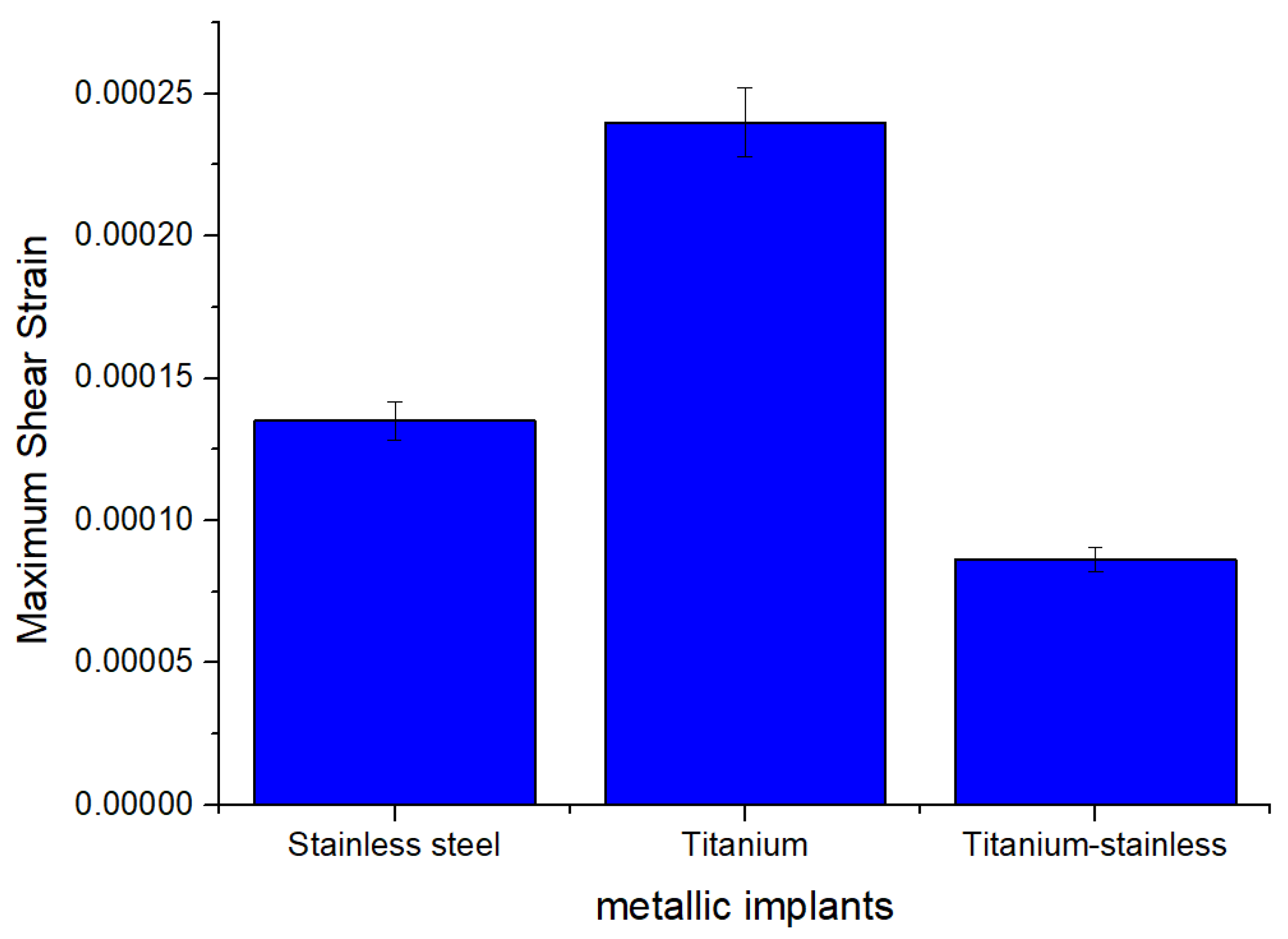
| Max shear elastic strain (mm) | Max | 0.0002401 | 0.00024011 | 8.6154 × 10⁻⁵ |
| Min | 3.5005 × 10⁻⁷ | 6.6302 × 10⁻⁷ | 2.506 × 10⁻⁷ | |
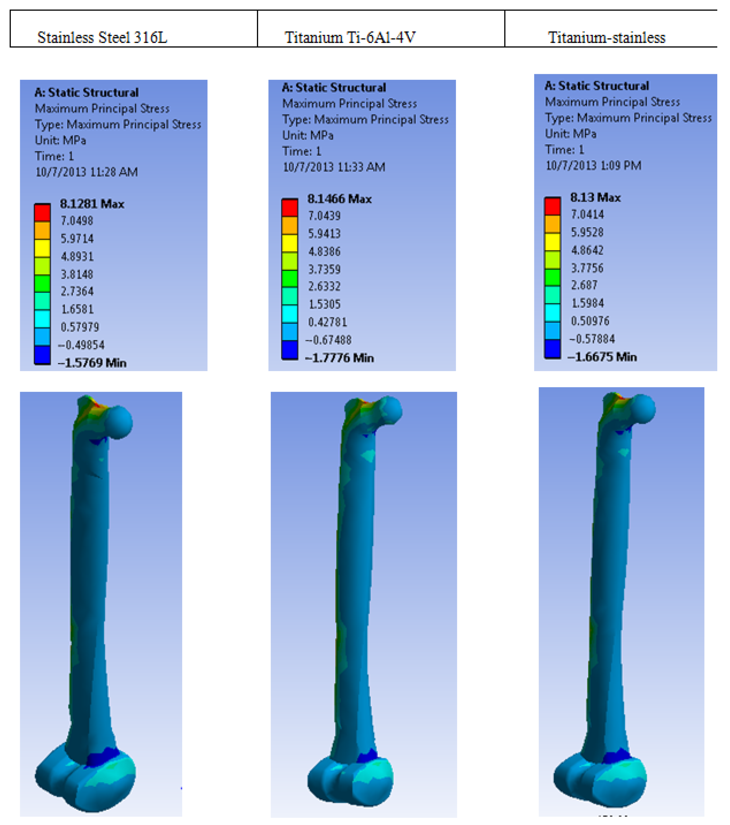
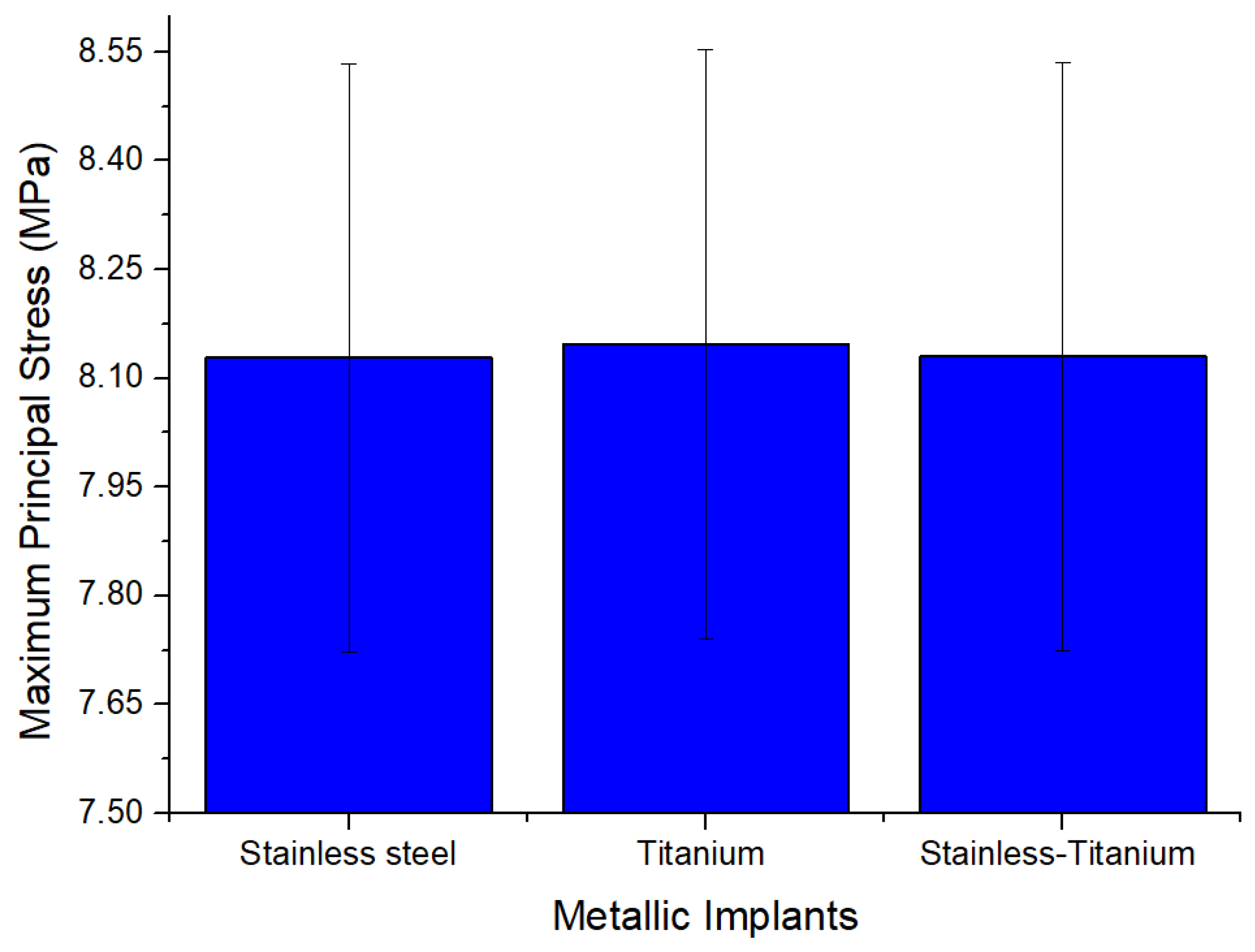
| Max Principal Stress (MPa) | Max | 8.1281 | 8.1466 | 8.13 |
| Min | −1.5769 | −1.7776 | −1.6675 | |
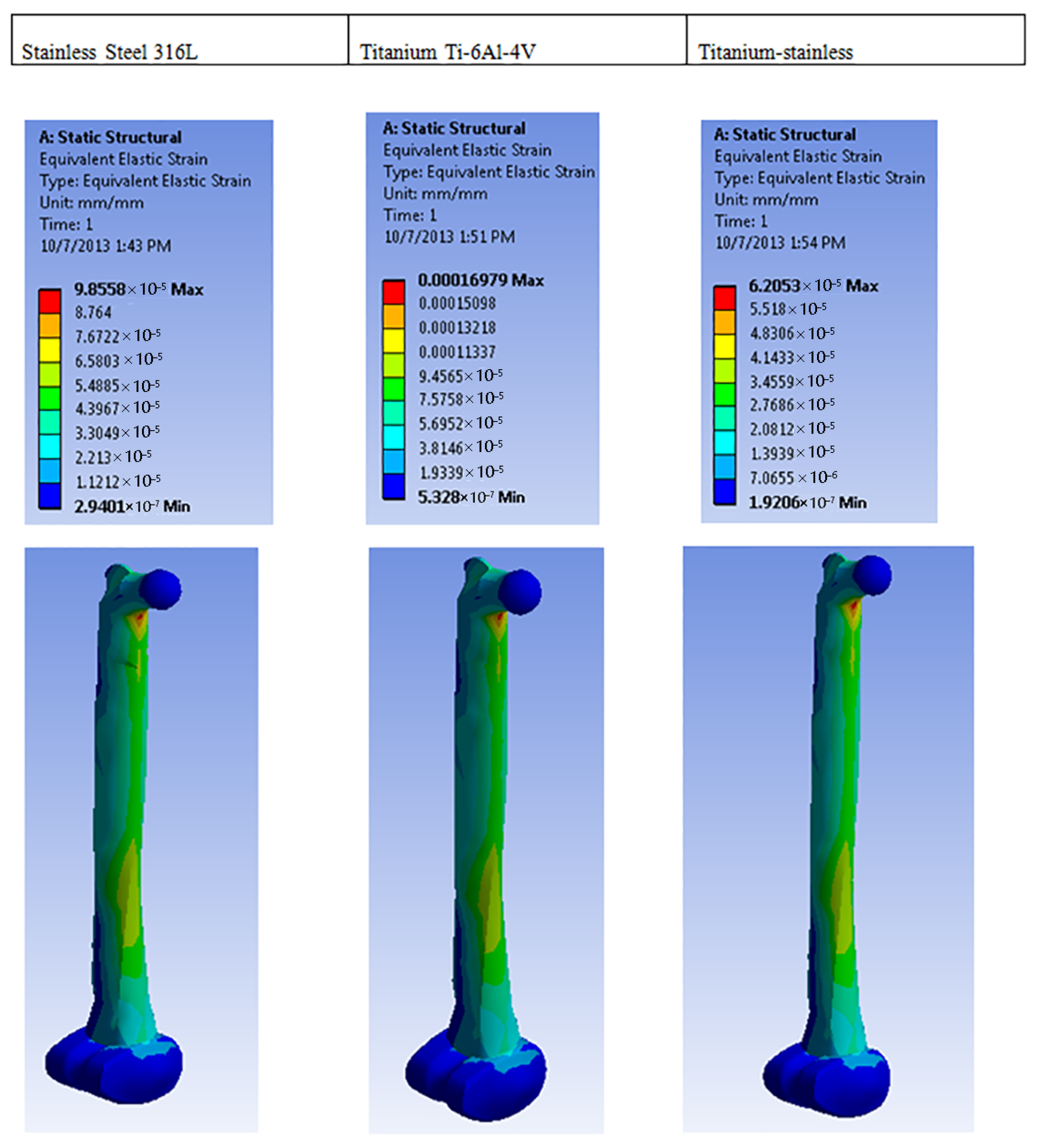
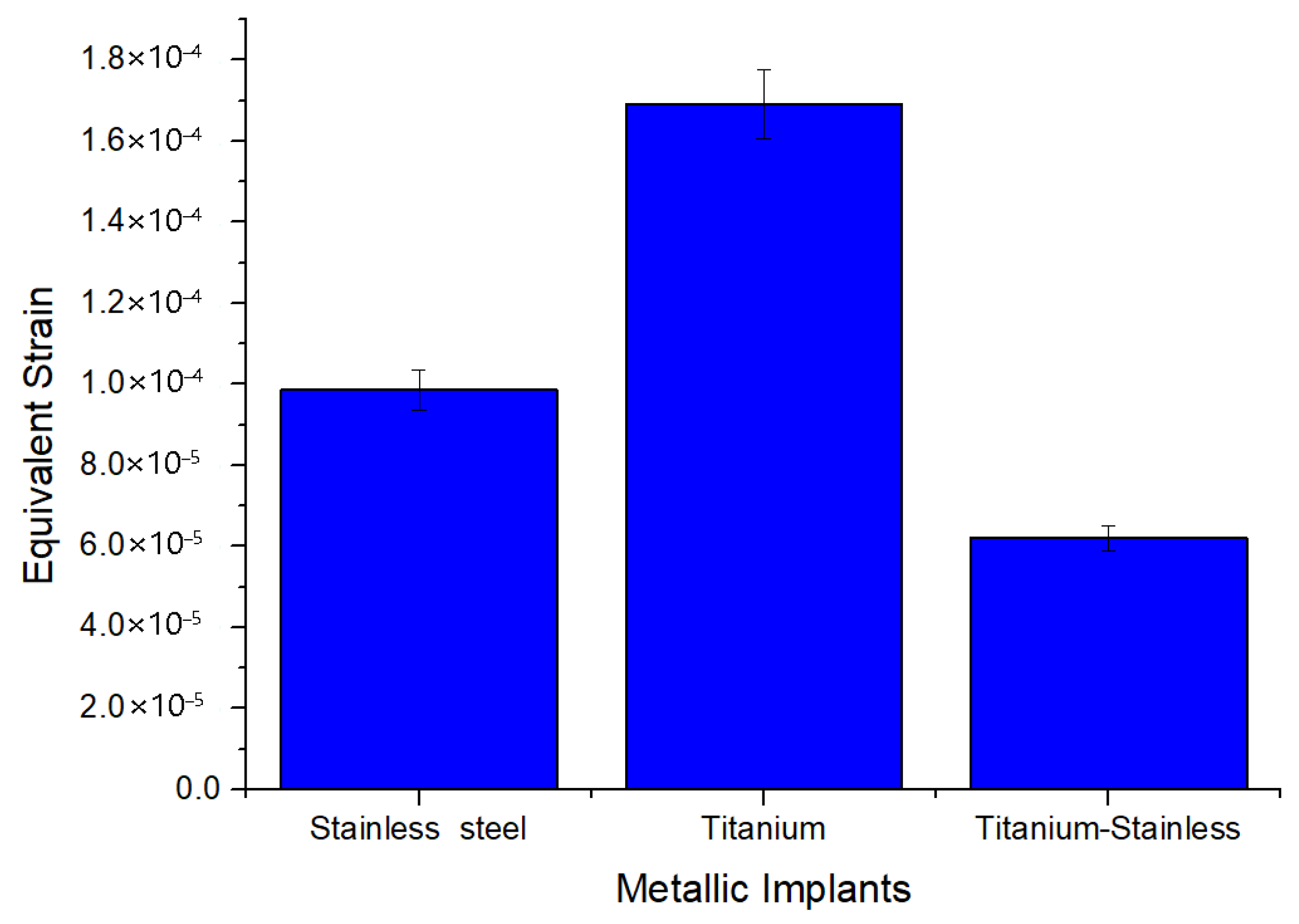
| Equivalent elastic strain (mm) | Max | 9.8558 × 10⁻⁵ | 0.00016979 | 6.2053 × 10⁻⁵ |
| Min | 2.9401 × 10⁻⁷ | 5.328 × 10⁻⁷ | 1.9206 × 10⁻⁷ | |
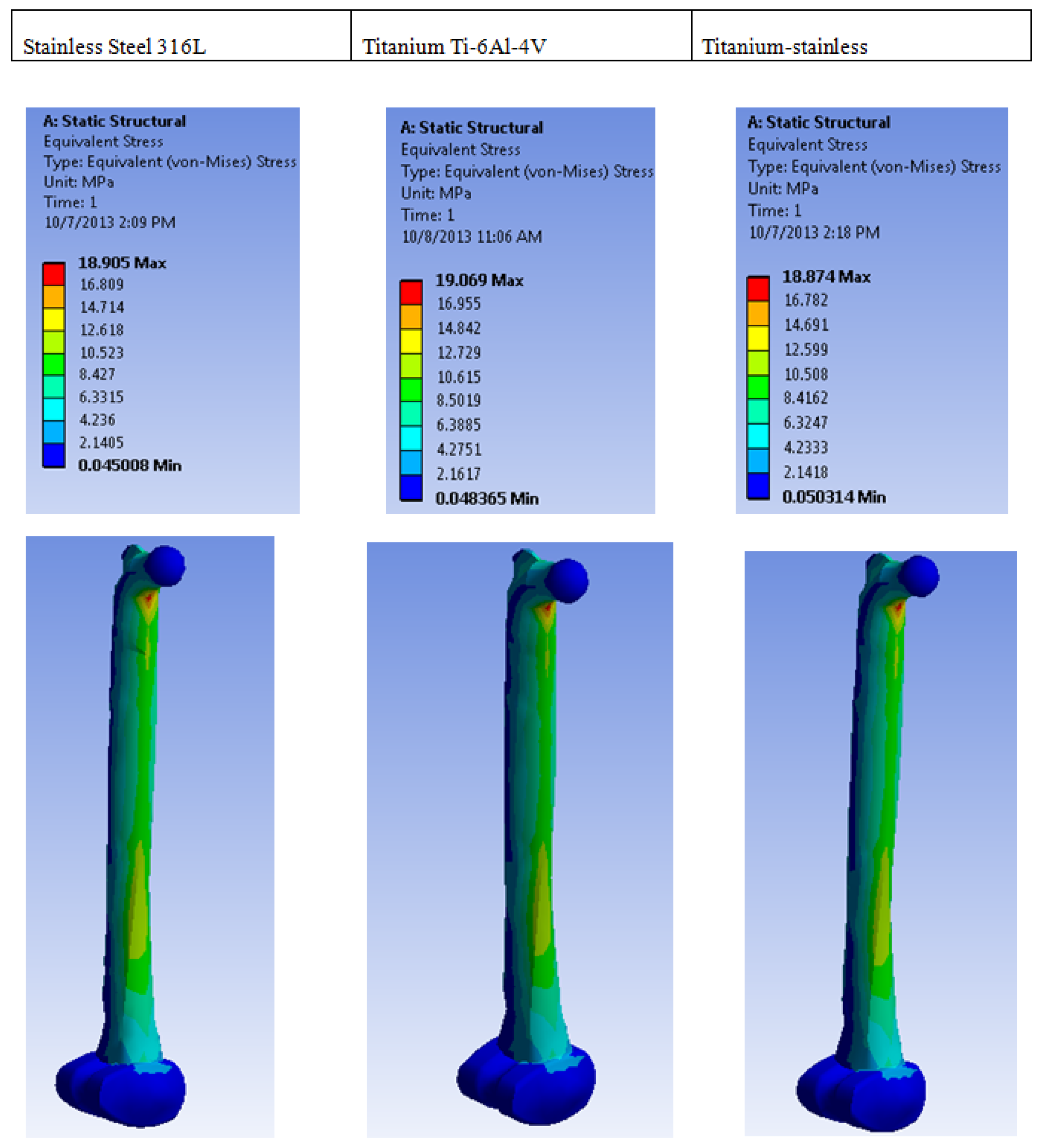
| Equivalent stress (MPa) | Max | 18.905 | 19.069 | 18.874 |
| Min | 0.045008 | 0.048365 | 0.050314 | |
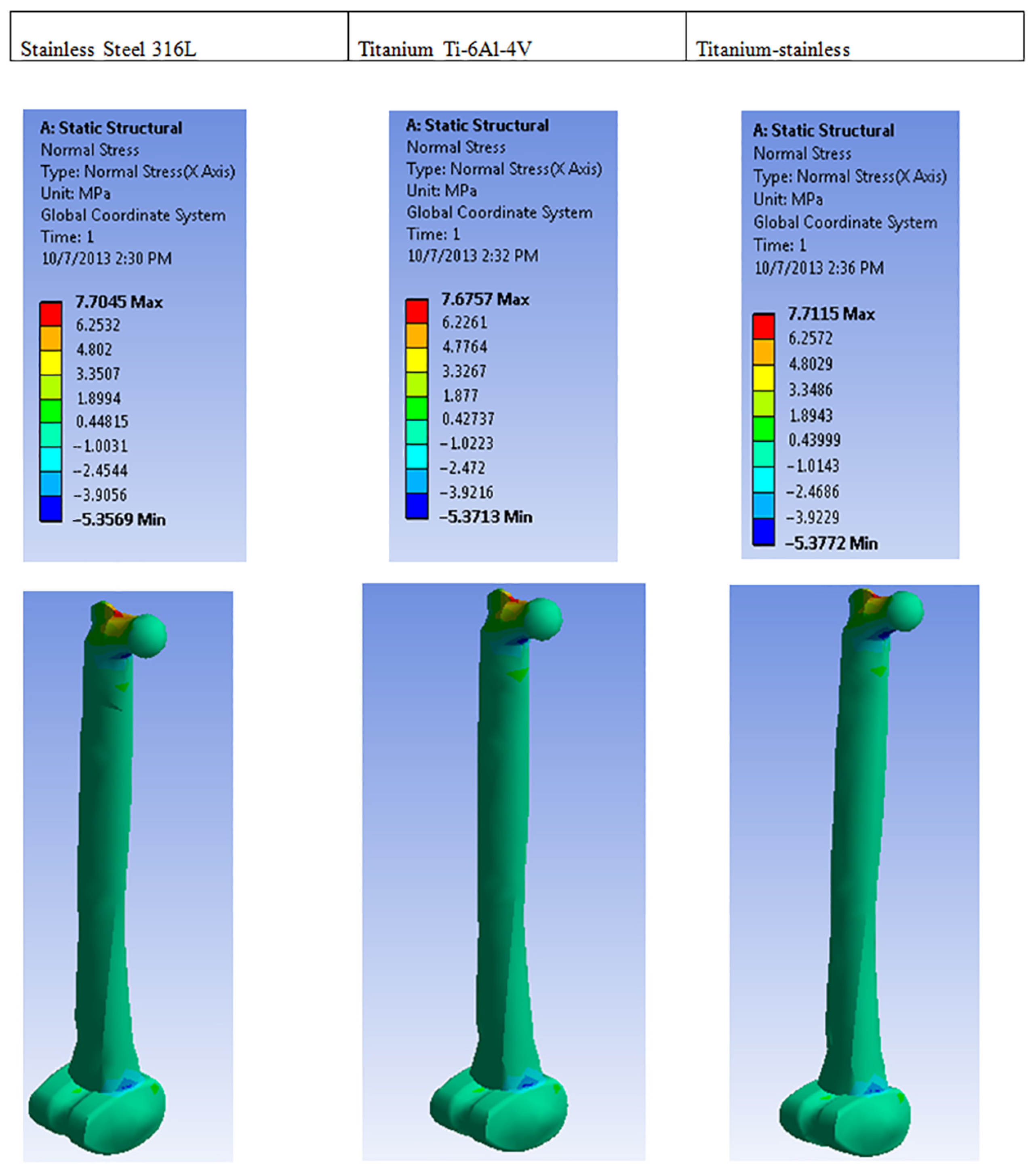
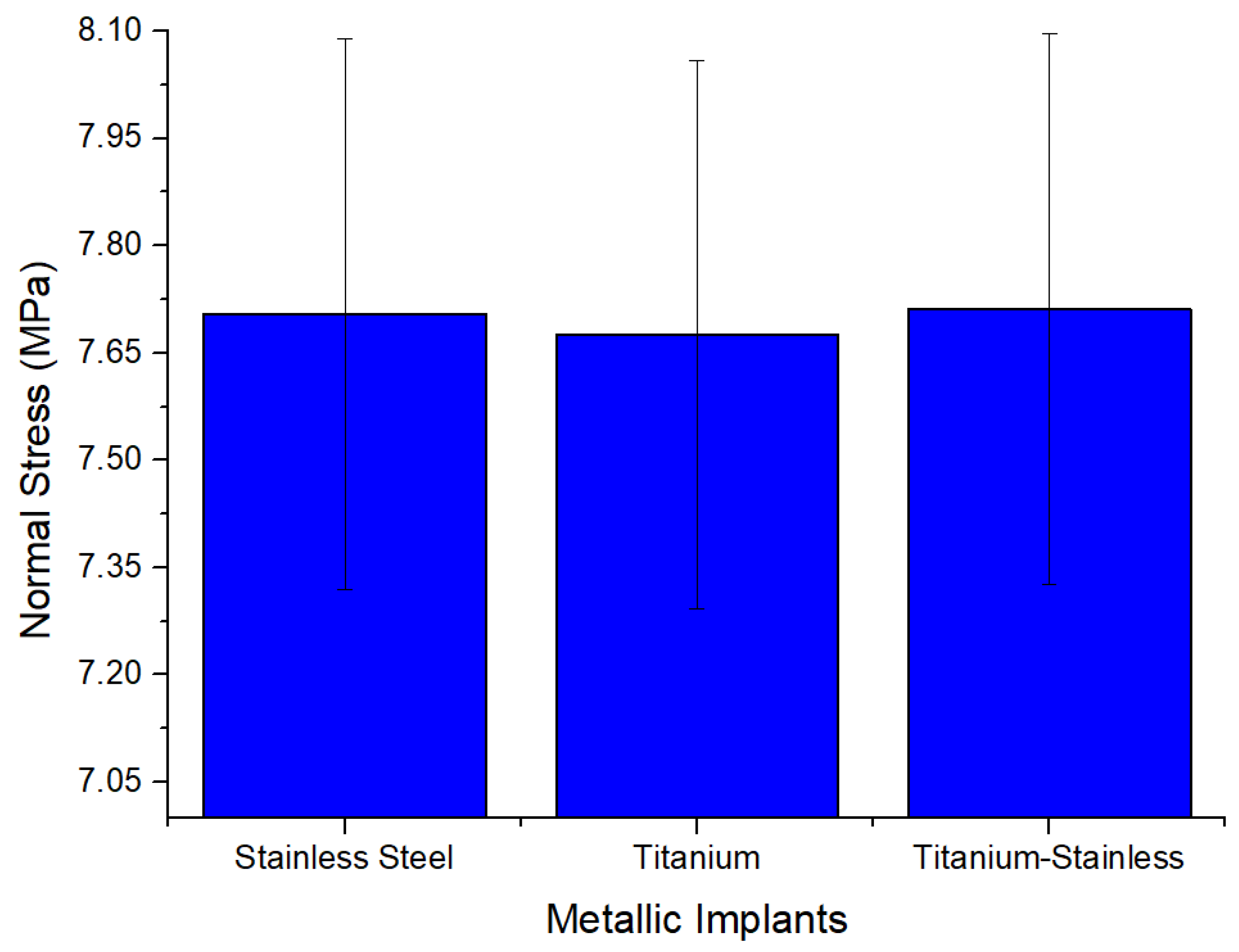
| Normal stress (MPa) | Max | 7.7045 | 7.6757 | 7.7115 |
| Min | −5.3569 | −5.3713 | −5.3772 | |
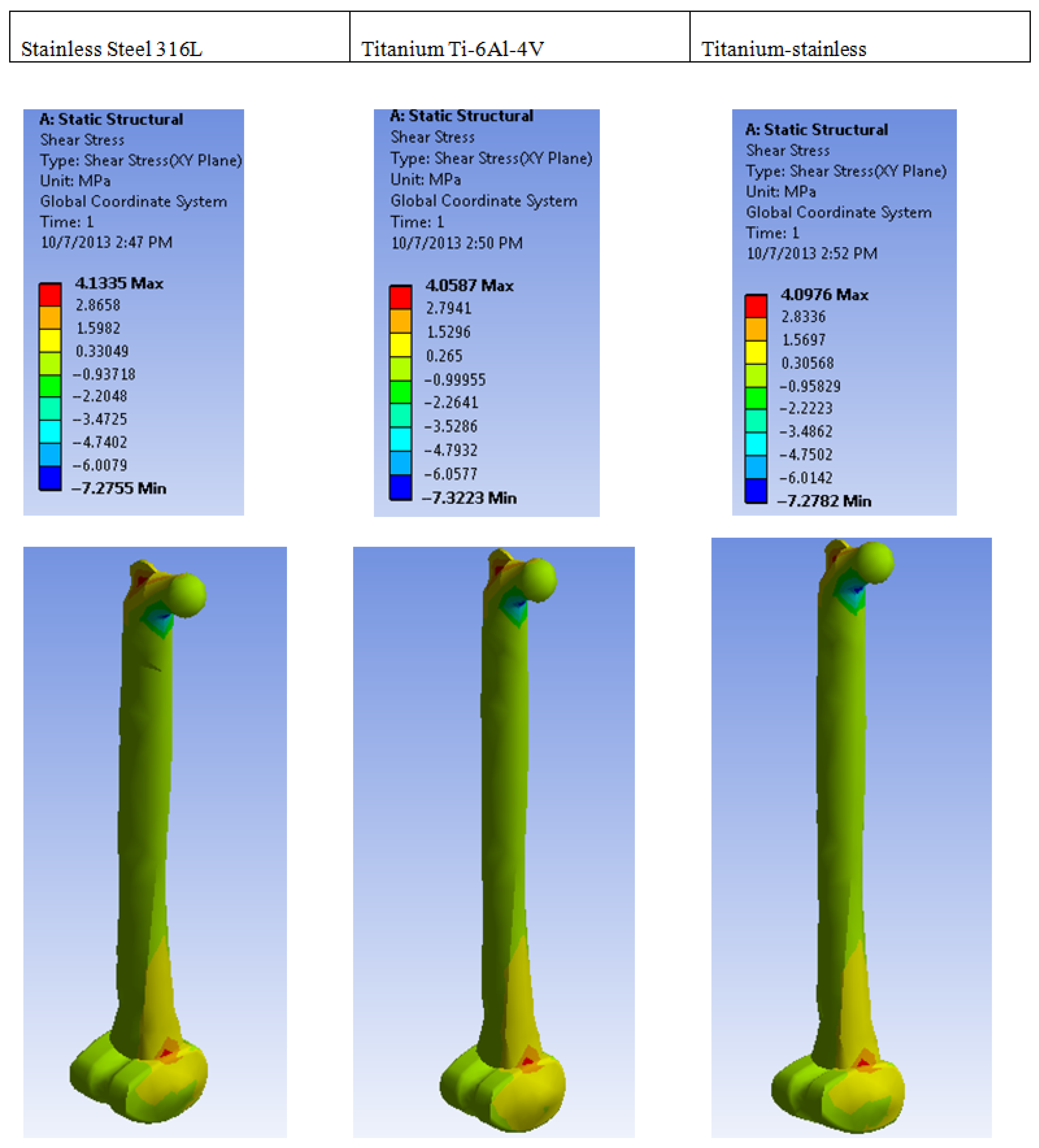
| Shear stress | Max | 4.1335 | 4.0587 | 4.0976 |
| Min | −7.2755 | −7.3223 | −7.2782 | |
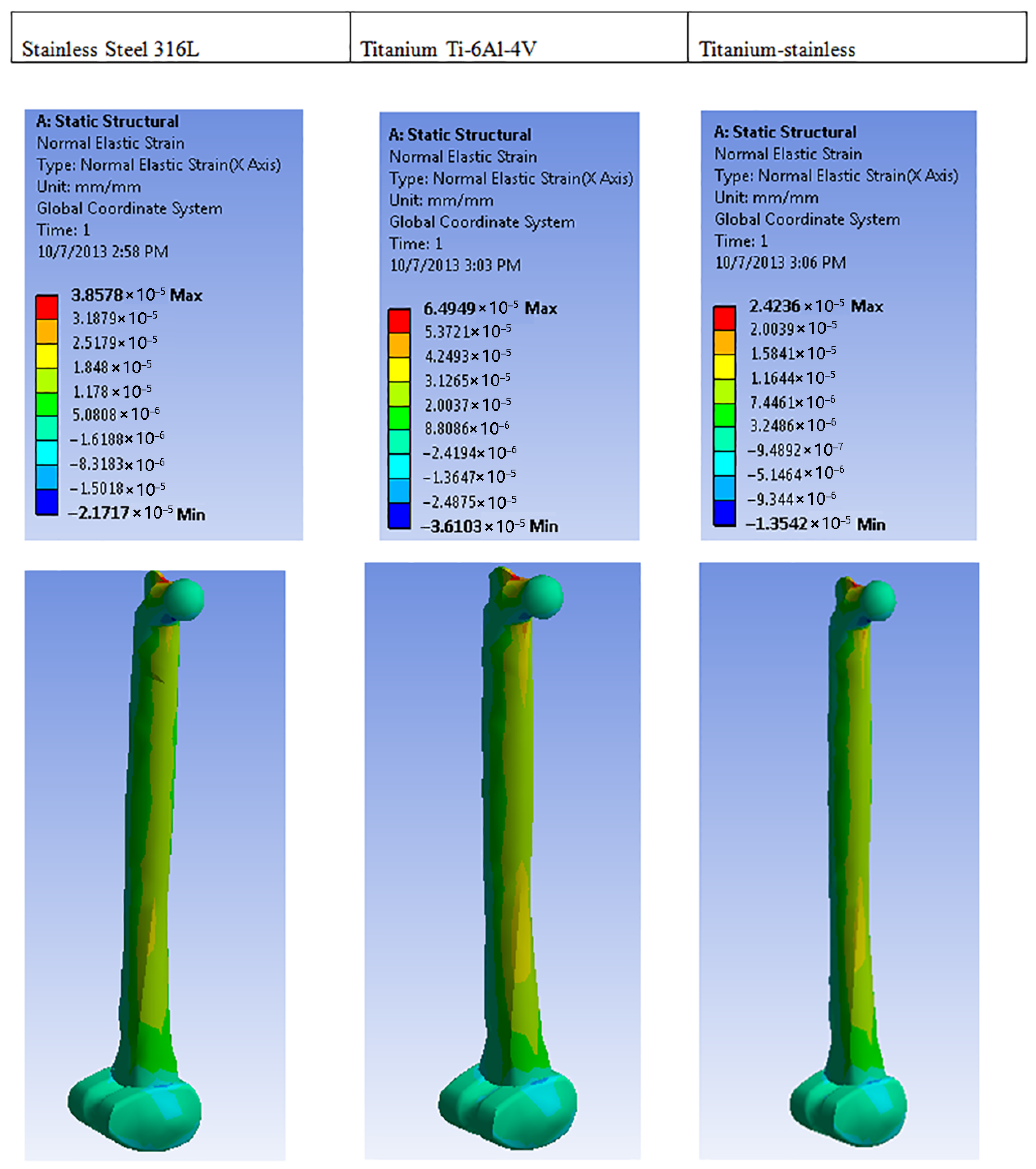
| Normal elastic strain | Max | 3.8578 × 10⁻⁵ | 6.494 × 10⁻⁵ | 2.4236 × 10⁻⁵ |
| Min | −2.1717 × 10⁻⁵ | 3.6103 × 10⁻⁵ | 1.3542 × 10⁻⁵ | |
| Shear elastic strain | Max | 5.5685 × 10⁻⁵ | 9.6402 × 10⁻⁵ | 3.5352 × 10⁻⁵ |
| Min | 9.8012 × 10⁻⁵ | −0.00017392 | −6.2792 × 10⁻⁵ | |
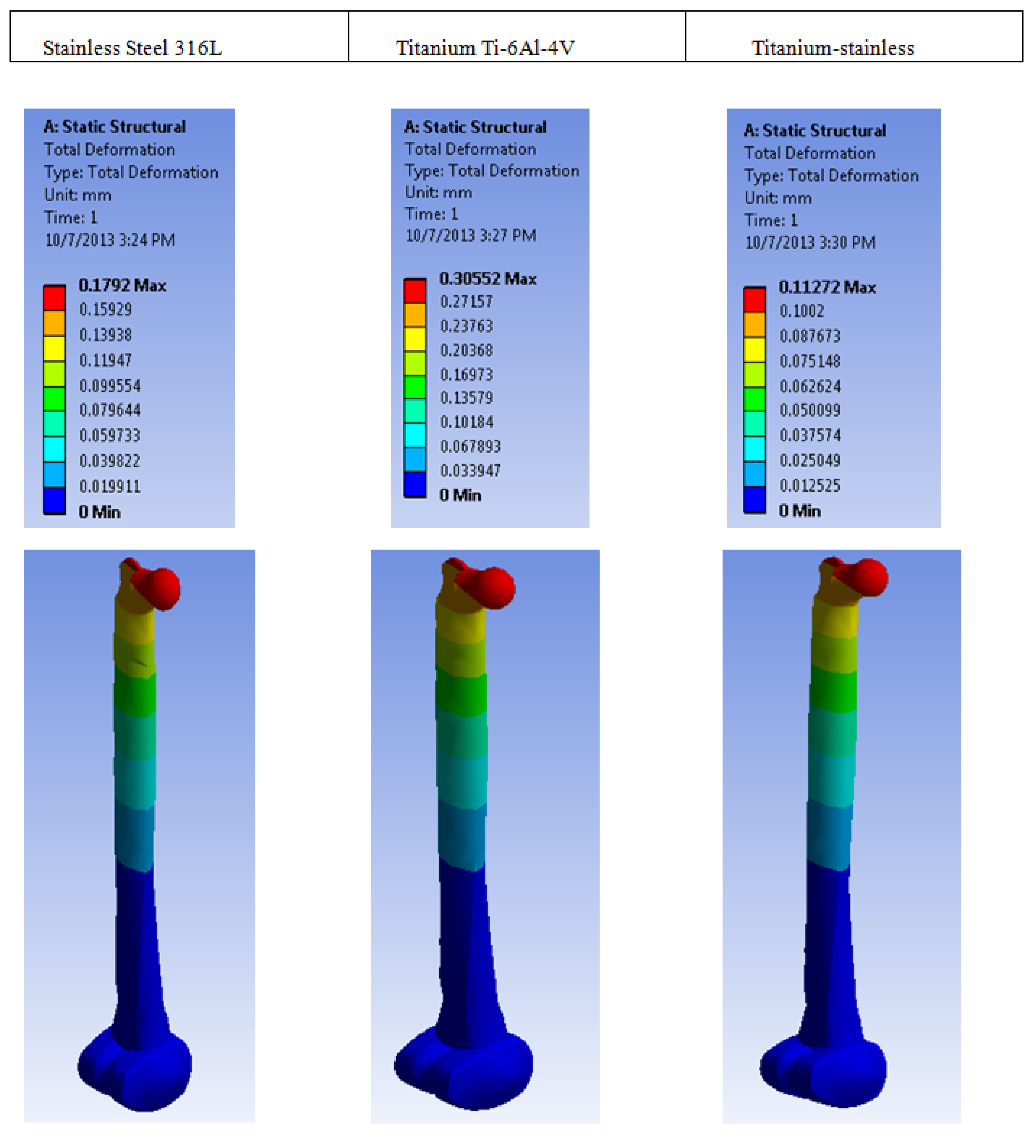
| Total deformation | Max | 0.1792 | 0.30552 | 0.11272 |
Disclaimer/Publisher’s Note: The statements, opinions and data contained in all publications are solely those of the individual author(s) and contributor(s) and not of MDPI and/or the editor(s). MDPI and/or the editor(s) disclaim responsibility for any injury to people or property resulting from any ideas, methods, instructions or products referred to in the content. |
© 2025 by the authors. Licensee MDPI, Basel, Switzerland. This article is an open access article distributed under the terms and conditions of the Creative Commons Attribution (CC BY) license (https://creativecommons.org/licenses/by/4.0/).
Share and Cite
Ikumapayi, O.M.; Bankole, O.O.; Bayode, A.; Onu, P.; Ting, T.T. Finite Element Analysis and Simulation of 316L Stainless Steel and Titanium Alloy for Orthopedic Hip and Knee Prosthetics. Prosthesis 2025, 7, 64. https://doi.org/10.3390/prosthesis7030064
Ikumapayi OM, Bankole OO, Bayode A, Onu P, Ting TT. Finite Element Analysis and Simulation of 316L Stainless Steel and Titanium Alloy for Orthopedic Hip and Knee Prosthetics. Prosthesis. 2025; 7(3):64. https://doi.org/10.3390/prosthesis7030064
Chicago/Turabian StyleIkumapayi, Omolayo M., Oluyemi O. Bankole, Abiodun Bayode, Peter Onu, and Tin T. Ting. 2025. "Finite Element Analysis and Simulation of 316L Stainless Steel and Titanium Alloy for Orthopedic Hip and Knee Prosthetics" Prosthesis 7, no. 3: 64. https://doi.org/10.3390/prosthesis7030064
APA StyleIkumapayi, O. M., Bankole, O. O., Bayode, A., Onu, P., & Ting, T. T. (2025). Finite Element Analysis and Simulation of 316L Stainless Steel and Titanium Alloy for Orthopedic Hip and Knee Prosthetics. Prosthesis, 7(3), 64. https://doi.org/10.3390/prosthesis7030064