Abstract
Rolling stock manufacturers are finding innovative structural solutions to improve the quality and reliability of railway vehicles components. Structural optimization processes represent an effective strategy for reducing manufacturing costs, resulting in geometries easier to design and produce. In this framework, the present paper proposes a new methodology to design a railway metro bogie frame, combining structural–topological optimization methods and sensitivity analysis. In addition, manufacturing constraints were included to make the component design suitable for production through sand-casting. A robust sensitivity analysis has highlighted the most critical load conditions acting on the bogie frame. Its effectiveness was verified by carrying out two different structural optimizations based on different loadings. Two equivalent designs were obtained. Computational times were positively reduced by about 57%. The maximum value of stress was reduced about 23%. This new methodology has shown encouraging results to streamline the design process of this complex mechanical system, allowing researchers to also include manufacturing requirements.
1. Introduction
Today, railway vehicles stand out as one of the optimal solutions for sustainable mobility, aiming to reduce air pollution generated by various types of land and non-land vehicles. The growth of the railway sector needs to address new challenges in both vehicle design and management. From a mechanical design perspective, one of the primary focuses is to standardize and make complex components such as a bogie frame increasingly replicable while allowing for easy customization based on the designer needs. This is why the use of diverse manufacturing techniques, such as sand-casting, supported by advanced numerical simulations, can lead to the realization of innovative and effective designs in rapid and acceptable timeframes. The ability to have a replicable bogie frame model would result in a significant improvement in production times, both for initial construction and in the event of damage and the subsequent need for component replacement. To achieve these goals, topological–structural optimization processes represent a fundamental tool supporting the design and development phase of the system under consideration. The available literature illustrates that not many studies about optimization processes, applied on railway vehicles’ bogie design, have been carried out. This aspect is even more accentuated for metro vehicles, the object of the present work. Generally, topological optimization and structural optimization processes represent effective techniques to design several classes of components. A control arm used in automotive applications has been optimized to reduce its mass [1,2]. A high-performance chassis design of an automotive vehicle body has been innovated using topological optimization [3]. Similar approaches have been used to improve the design procedure for turbomachinery components, especially if combined with additive manufacturing techniques [4,5,6,7,8]. Referring to railway applications, the anchor bracket has been redesigned by taking advantage of a topology optimization process and introducing composite materials [9].
Many researchers have optimized the car body oriented towards a lightweight design process [10,11,12].
Size optimization and modal behavior of the car body structure have been combined to propose a new design procedure for the car body [13,14].
A major part of the applications that involve manufacturing constraints are referred to as general applications. A Heaviside parametrization design to obtain manufacturable cast geometries adopting a gradient driven topology optimization approach is reported in [15]. In [16], a comparison between two casted parts designed through optimization process, with and without manufacturing constraints, is presented. A structural optimization approach focused on the bogie frame of a freight wagon and its bolster is described in [17]. The objective was a mass reduction in the system. A topological optimization was conducted using the SIMP method to maximize the stiffness of the structure. The bogie frame of a tilting train for Korean railways has been redesigned exploiting an optimization approach based on a microgenetic algorithm [18].
Furthermore, the literature highlights the importance of railway bogie frame life prediction. Multibody dynamics and a finite element approach have been combined to simulate the behavior of bogie frames under real operational service loads [19]. A rigid–flexible coupled vehicle dynamic model has been adopted to estimate the dynamic response acting on a high-speed train [20]. Similar approaches, applied on different types of bogie frame, have been proposed by other researchers [21,22,23]. Lifetime assessment and optimization have been applied on a welded a-type frame for a mining truck [24]. Experimental fatigue evaluation has been carried out on a metro bogie frame [25,26]. Stress and acceleration tests on the bogie frame of a diesel multiple unit (DMU) have been performed to clarify the reasons for fatigue cracking [27]. However, all of the proposed techniques aimed to assess the performance of the vehicle without considering component redesign and innovation.
In this research activity, the frame of a railway bogie used for a metropolitan vehicle was studied to create an innovative design. A robust campaign of topological–structural optimization was conducted on the component with the aim of achieving an appropriate simulation setting. Two main aspects characterized the novelty of this research. The first involved the utilization and control of technological constraints oriented towards an innovative and potentially manufacturable design for sand-casting. This approach is yet to be explored in the railway field, especially for critical components such as railway bogie frames. The second innovation included the implementation of a comprehensive sensitivity analysis to understand the most critical load conditions used for the mechanical verification of this component. This allowed for a streamlined and focused structural optimization based on the sensitivity analysis results. Significant reductions in computational times were achieved. The obtained design proved to be consistent and practically identical to that obtained through the complete simulation, fully meeting the objectives of this research activity. In addition, improvements in terms of stress distributions and concentrations were observed.
This paper is organized in four sections, including the introduction of Section 1. The bogie frame used as benchmark, the proposed methodology and the main modeling steps are described in Section 2. Section 3 reports all the results and discussions about sensitivity analysis, structural optimization, static and fatigue structural verification and frame redesign. Finally, in Section 4, the conclusions and future developments of the activity are presented.
2. Materials and Methods
In this section, the methodology that was followed during the present research activity is presented. First, a brief presentation of the metro bogie frame is reported. Then, the structural optimization process and the sensitivity analysis approach are explained in detail.
2.1. Model Description: The Metro Bogie Frame
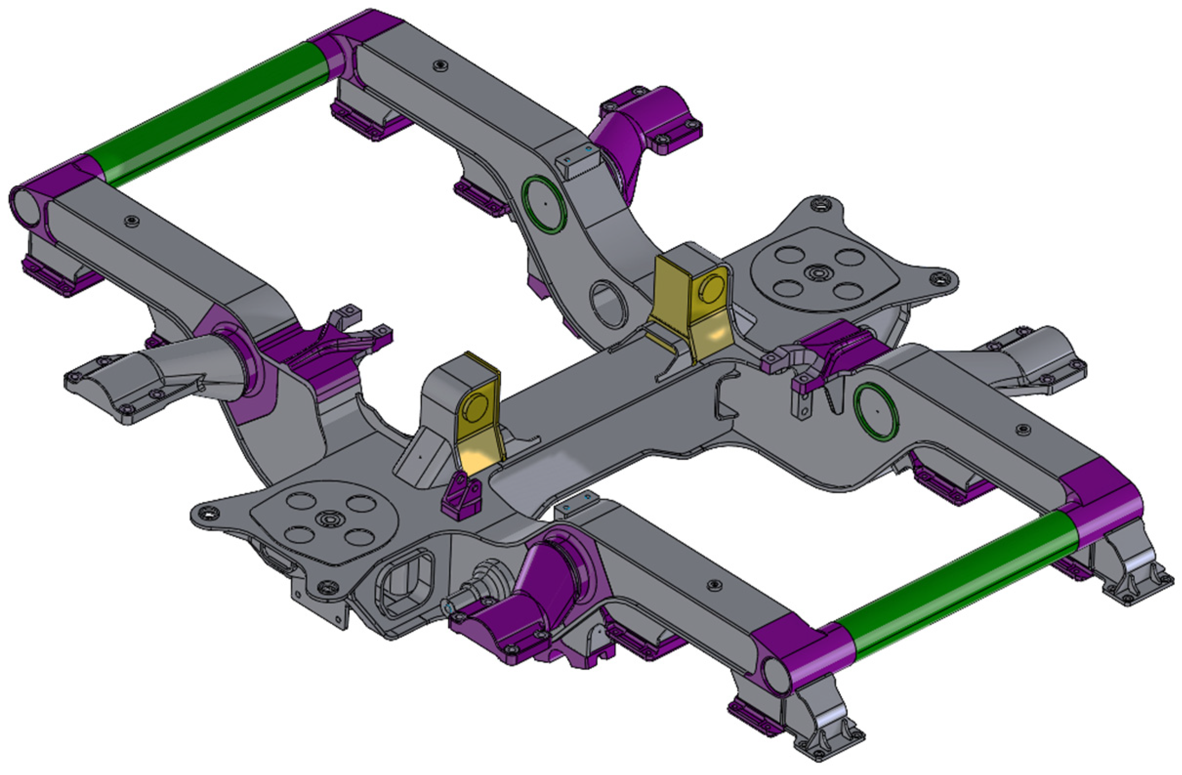
The metro bogie frame is a crucial structural component designed to support and integrate various elements within the train undercarriage. The robust frame provides the necessary strength, durability, and resilience required for the demanding operational conditions of a metro system. The frame is meticulously made through precision welding techniques, ensuring a seamless and uniform connection of steel components. However, welded joints represent the main critical aspect of these complex mechanical systems, especially from the mechanical fatigue point of view. The frame consists of interconnected beams, cross-members, and other geometric configurations strategically designed to distribute the load evenly across the structure. This design not only enhances the bogie stability but also contributes to the overall safety and efficiency of the metro system. The structure of the original bogie frame was made up with construction steel and assembled through welding, as described above. Figure 1 illustrates a complete view of it.

Figure 1.
View of the original metro bogie frame.
The perimeter crossbeams (green color in Figure 1) had a circular section and provided a significant contribution to the frame resistance against all torsional loads. Their end elements were directly welded to the main longitudinal members. The device for supporting the brake components, as shown in Figure 2, consisted of an unalloyed steel element that was laterally welded to the outer surfaces of the longitudinal members in an area near the primary suspension.
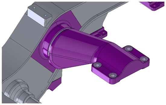
Figure 2.
View of the original braking support system.
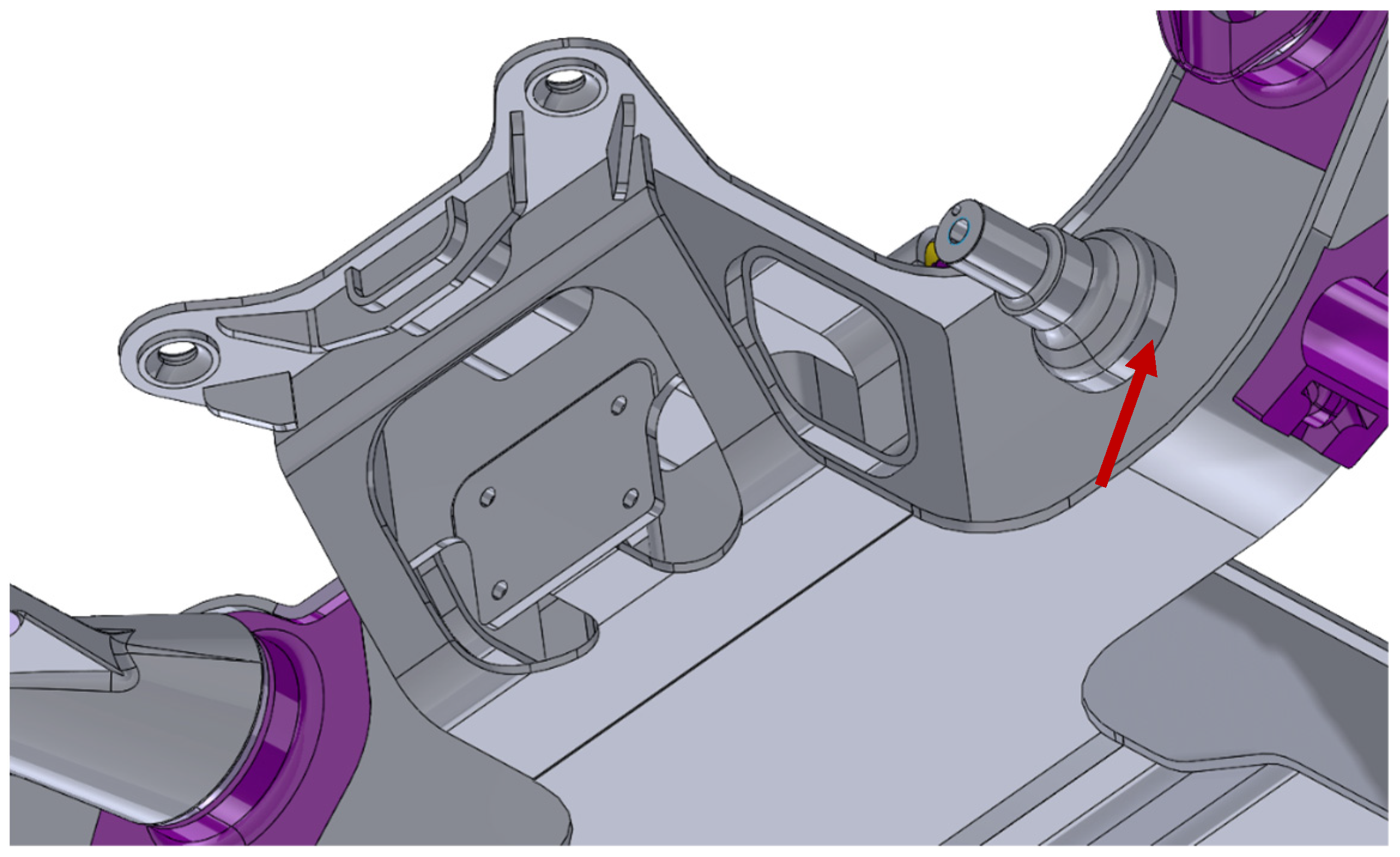
The support for the traction link was a rotational component initially fitted onto the longitudinal member through a hole and subsequently welded to the structure peripherally. It was important to highlight the hollow structure underneath the secondary suspension housing, designed to facilitate the passage of the traction link, properly connected to the bolster beam at the other end. The components described are clearly visible in Figure 3.

Figure 3.
View of the original traction link zone.
Other crucial elements included the support for the gearbox system, located on the shoulder of the longitudinal beams and properly welded to its upper flange. The engine support was positioned near the traction link. Finally, the last component essential for understanding the force exchange is a welded element near the housing of the secondary suspension, responsible for transmitting transverse forces from the cylinder connected to the bolster beam (visible in Figure 1 and colored purple).
2.2. Methodology
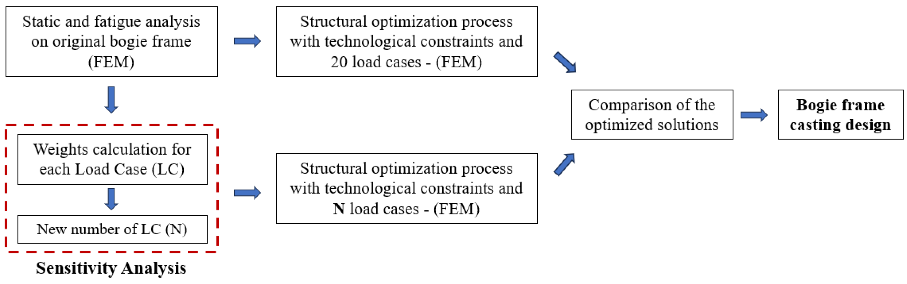
The methodology adopted by the authors for the innovation of the present metro bogie frame is briefly described and summed up in Figure 4. It aims to combine the CAD environment, FE calculation and a structural optimization process which involves technological constraints oriented to the sand-casting process. One important objective of the activity was to create a suitable bogie frame design to produce it with a sand-casting process. It represents a real innovation in the railway field, where this type of mechanical system, due to its complex features, it is always made up of structural steel and assembled through a welding process. In order to assess the performance of the final design, the real performance of a material potentially suitable was included. In detail, the reference material was EN-GJS-450-10, the mechanical characteristics of which can be found in [28]. The main innovative approach of this research work involved the implementation of a robust sensitivity analysis of the loading conditions to which railway bogies are subjected. The primary objective was to expedite the complex structural optimization processes, which can take up to consecutive days of computational time. Secondary, the optimization process must converge to the same topology result to confirm the effectiveness of the sensitivity analysis. Then, two classes of optimizations were carried out to find the final design of the bogie, comparing mass distribution and calculation time.
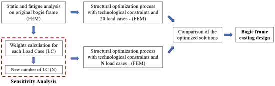
Figure 4.
Main steps of the methodology.
First, the metro bogie frame was tested numerically according to the load conditions listed in reference standard EN 13749:2021 [29]. In detail, 20 load cases were tested, including static and fatigue load conditions. These are listed and described in Table 1.

Table 1.
Load case conditions.
Each load case was composed of several contributors. For this reason, all of the descriptions cite the main forces involved in the single case, without entering formulations and values, which is not useful for the comprehension of the present work. All the load cases between S01A and PR10 are static load cases, while others are used to test fatigue conditions.
2.3. Finite Element Model of the Bogie Frame
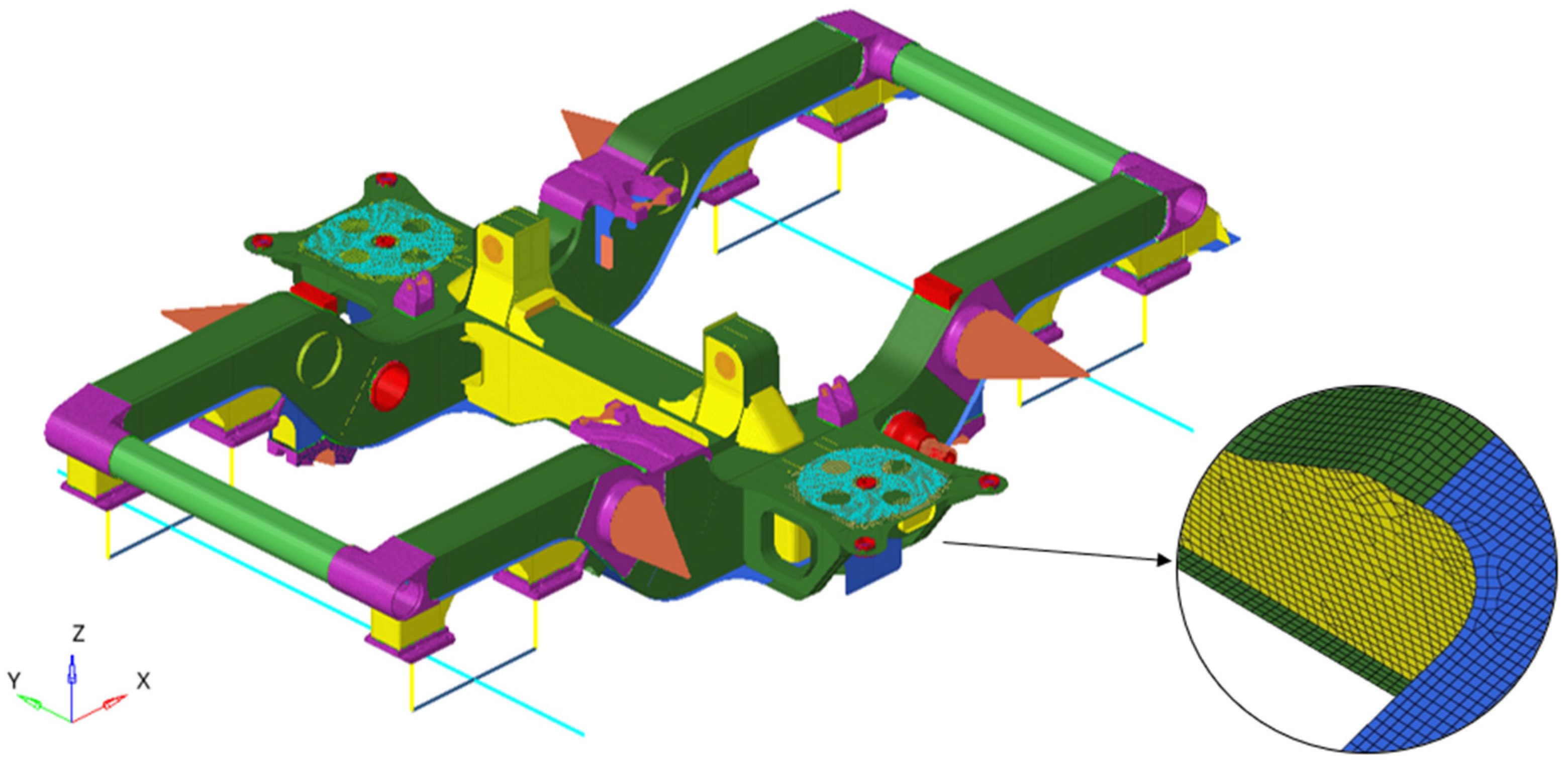
The finite element model of the starting bogie frame was a high-level representation of the system, made with an FE commercial software. Figure 5 illustrates it and a meshing detail in the most critical area. The structure of the component, including the central crossbeam, the longitudinal beam, and the perimeter crossbeams, was modeled using a two-dimensional mesh consisting of SHELL elements of QUAD4 type, with an average size of 10 mm and a minimum size of 3 mm. The sensitivity analysis performed on the component grid allowed us to ensure the good quality of the mesh and reliable results, especially for stress evaluation. All the supports described in the previous section, on the other hand, were composed of a three-dimensional mesh of second-order TETRA elements (TETRA10 type), with the same dimensions as the two-dimensional elements. The choice of different types of elements depended on the characteristics of the components. The bogie frame featured thinner thicknesses well represented by the numerical formulation that describes the mechanical behavior of shell elements. On the other hand, the supports had three-dimensional development geometries that necessitated solid elements. These two types of mesh could not be connected directly, as the 2D mesh had elements of the first order. An effective solution was found to join to the main structure all the supports modeled with solid mesh: the use of a freeze/bonded contact. This type of contact configuration ensures the linearity of the model, and the complete redistribution of all the stresses acting (both forces and moments). In detail, it enforces zero relative motion on the contact interfaces, the gap between them remains fixed at the original value and the sliding distance is forced to be zero. In this way, the use of the FE model was improved, ensuring the accuracy of the results and simplicity of modeling. Another important advantage of this approach was to be able to separately modify both the supports of the various subsystems and the main frame, increasing the speed of potential changes and subsequent numerical tests. Loads were applied with different approaches, according to the application zone. In addition to classical forces and pressure, zero-dimensional RBE3 elements were also utilized. These elements prevented the addition of stiffness to the structure, effectively distributing the loads among the respective nodes. The primary suspension (yellow color), which acted as a suspensive stage between the wheelset and the bogie frame, was modeled using one-dimensional elements. The accurate representation of this system was of crucial importance as it was essential to faithfully replicate this specific connection point, avoiding the introduction of excessively stiff constraints that could generate extremely high stresses, which did not result in realistic outcomes. The modeling of the axle (light blue color) and the pin seat was accomplished using one-dimensional beam elements with congruent sections. The conical rubber–metal suspension was simulated by employing two one-dimensional spring elements connected through two rigid multi-node elements of type RBE3 to the supports where the suspensions were located. Constraint conditions, for all load cases, were represented by an isostatic configuration, as reference points of the four wheels, positioned at the end of the axle. The model consisted of 572’513 elements and 692’502 nodes.

Figure 5.
Finite element model of the starting bogie frame.
2.4. Sensitivity Analysis
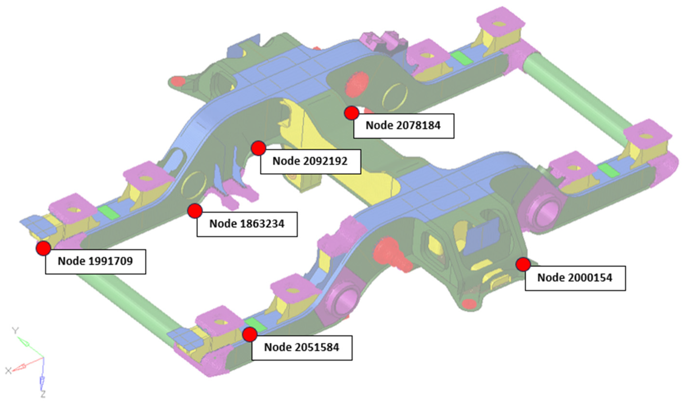
Sensitivity analysis is a fundamental analytical process employed across various scientific domains with the aim of understanding how variations in the values of parameters within a complex system or mathematical model impact the outcomes or performances of that system. The process examines how variations in input data can propagate through these parameters, causing changes in the results achieved. Generally, this methodology consists of five fundamental steps: quantifying the uncertainty in each input, varying the parameters, identifying the model outputs to be analyzed, simulating the model a number of times, and calculating the sensitivity coefficients. The sensitivity study was conducted on the 20 load cases applied to the original bogie frame. The aim of this analysis was to understand how variations in load cases influenced the structural performance of the bogie, thereby identifying the most significant load scenarios. As the first step, the selected output were the stresses calculated at 6 critical points of the structure, identified following static and fatigue analyses. The choice of these points aimed to comprehensively represent the mechanical behavior of the entire bogie. Depending on the considered load case, the structure experienced varying stresses, and stress concentrations were observed in potentially distinct areas. In this regard, the chosen nodes allowed us to account for these effects. Figure 6 approximately shows the position of the six critical nodes.

Figure 6.
Critical nodes selected for the sensitivity analysis.
The second step involved quantifying the uncertainty for each chosen output. All load cases were analyzed, remembering that each was composed of a combination of a certain number of loads. Each contribution was tested at 25%, 50%, 75%, and 100% of the value required by the reference standard. This approach allowed for the consideration of realistic variations in the loading conditions to which the bogie frame could be statistically subjected, as well as verifying the linear behavior of the calculated outputs. It was demonstrated that by varying the percentage of each load contribution, stresses would vary linearly, thereby maintaining the criticality of the considered load cases unchanged. This analysis was conducted on all critical nodes, and the results are reported in Section 3.1. The sensitivity coefficients allowed us to quantify the importance of input parameters and understand how variations in these parameters propagated into the model results. To assess the uncertainty of the inputs, the normalized index was chosen. This was a dimensionless measure that standardized the input parameters so that they were comparable. In practice, it expressed the variation in each parameter relative to its range or maximum value. Expression (1) provides its definition.
where the index i indicates the various critical points used in the sensitivity study and index j indicates the different load scenarios. is the local normalized index for node i and load scenario j, is the stress in the critical node i calculated for the load scenario j, and represents the maximum stress for the single critical node i, varying j. Subsequently, a new index representing each load case at a global level was calculated. It was referred to as the Global Index (). The new index was computed as the sum of the normalized values recorded at critical nodes for each load case. This approach allowed us to highlight the overall effect of parameter variations on all outputs, thereby identifying the most influential cases affecting the original bogie frame. Expression (2) describes it. All of the results related to this index are reported in Section 3.1.
2.5. Topological Optimization Settings
The topological optimization process conducted on the metro bogie frame during the present study served a dual purpose: to demonstrate the effectiveness of the sensitivity analysis performed under the loading conditions prescribed by the reference standard for component verification and to propose an innovative design for the frame. This design aimed to feature shape and geometry characteristics oriented to its realization through a sand-casting process. Technological constraints were introduced to guide the solver towards this solution in alignment with the second objective. The optimization process was executed using commercial software employing the gradient method as the solving algorithm. The user defined all input parameters for the optimization analysis, while the solution process was autonomously managed by the software. The solution was based on the Gradient-based Optimization Method [30].
The main difference between the two topological optimizations was in the number of load cases upon which these were based on. Once completed, a comparison in terms of material distribution and calculation times was carried out. It was fundamental to establish the effectiveness of sensitivity analysis on the load cases selection. Regarding the settings of the optimization processes, they are summed up in Table 2.
Table 2.
Optimization settings.
The optimization process had the objective of minimizing the weighted compliance calculated on all the load cases. The compliance is the sum of the strain energy of the mechanical model. The higher the value, the more the model is deformed under the same load. This essentially defines an inverse measure of stiffness, allowing the formulation of a more efficient minimum problem. As illustrated in Figure 7, before starting the procedure, the model of the bogie was adapted to be processed. With the aim of providing greater freedom to the optimizer for defining a new bogie design, the material volume of the frame was increased and geometrically simplified, using simple geometries and volumes. The dimensions were kept within an acceptable range defined by the mechanical component dimensions. The partitioning of design and non-design space was fundamental, allowing for the definition of the portion of material on which the solver could act. In Figure 7, the design space is shown in light blue, while the non-design space is represented in red. The non-design space mainly included areas of interface with other systems, load application zones, and connection zones to supports. Giving special attention to the latter, this choice allowed for the main interfaces to remain unchanged, enabling the separate management of modifications to the main frame and those to the supports.
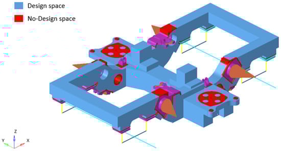
Figure 7.
Topological optimization base model: design and non-design space.
The optimization constraint was imposed on mass fraction. It is the ratio between the final and the initial mass of the design space. It was set below 40%, a value generally adopted for topological optimization. The “Pattern grouping” setting allowed for the introduction of a symmetry condition with respect to a midplane of the bogie frame with the normal orientation along the y-direction. This condition was needed due to the characteristics of the loads that were applied only on one side of the bogie, creating an asymmetrical distribution of the material. After several tests, the value of the “Minimum feature size” setting was defined equal to 25 mm. It allowed us to ensure the correct level of detail in the optimized geometry. Finally, the “Draw single” setting forced the removal of material along a predefined direction. This technological constraint aims to simulate the extraction of the model from a mold, creating a geometry opened in the upper side or lower side, depending on the direction set.
3. Results and Discussion
3.1. Sensitivity Analysis: Uncertainty Quantification and Global Index
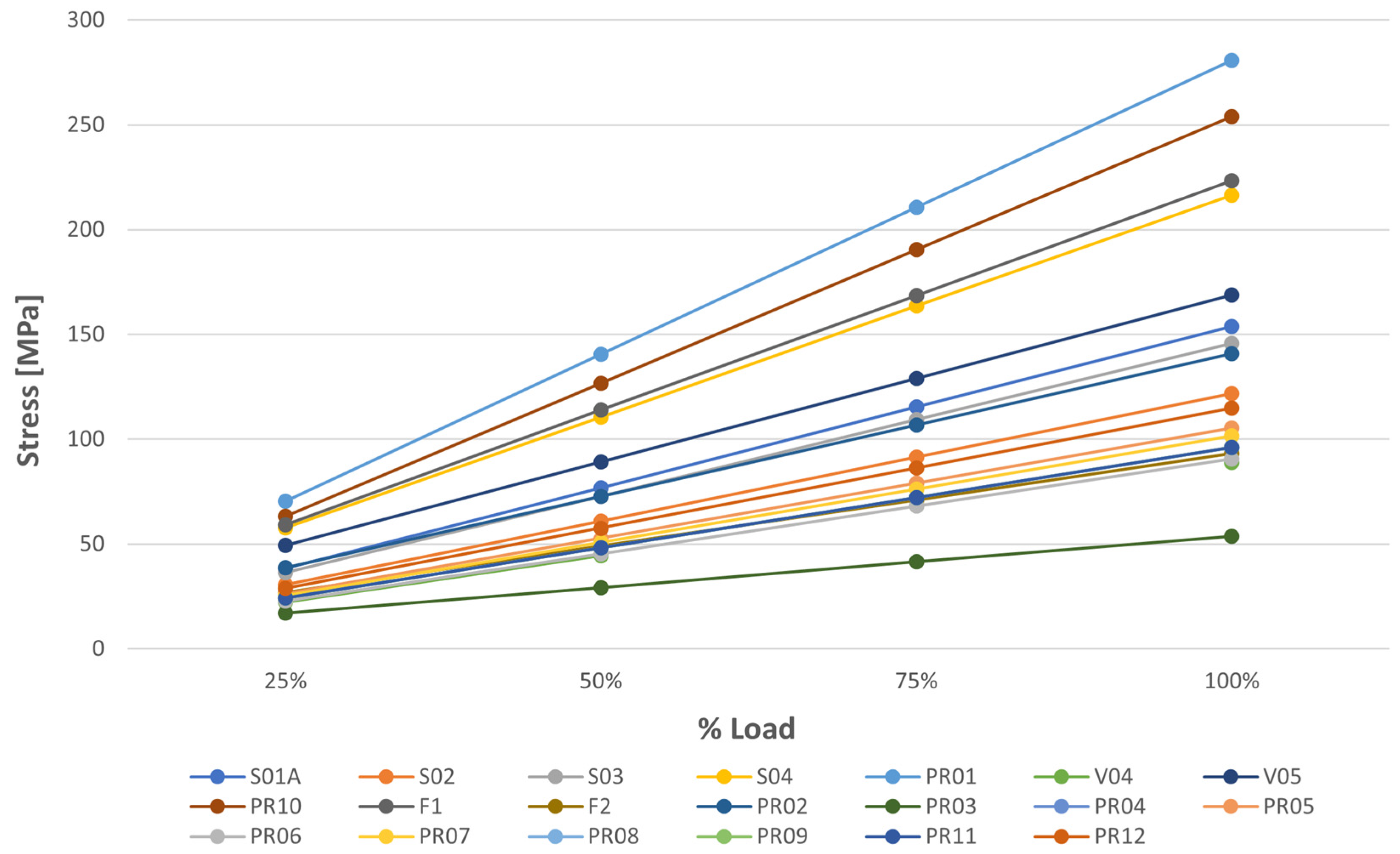
The uncertainty on the output used for the sensitivity analysis was assessed by varying all the load cases in three main percentages with respect to the full value: 75%, 50%, and 25%. This approach allowed us to check the linearity of the response and to evaluate realistic changes in the load. The responses were the stresses calculated in the six reference nodes. Figure 8 illustrates the results of the calculation carried out on node 2078184. The linearity of the outputs was confirmed.
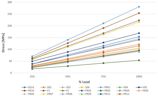
Figure 8.
Output linearity assessment on node 2078184.
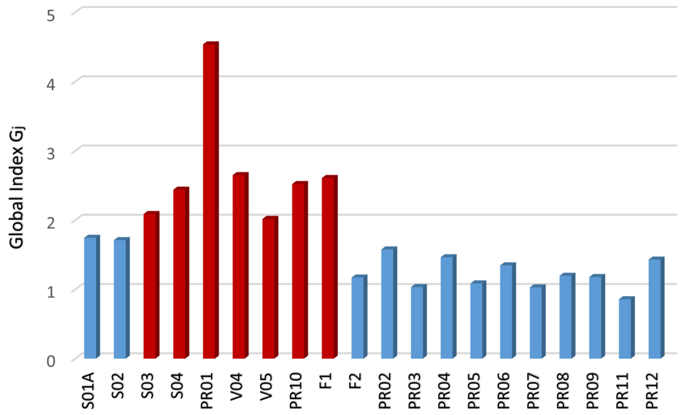
Consequently, the Global Index was assessed for all loading conditions on all nodes. The analysis showed seven critical load cases, with a Global Index value significantly higher with respect to the other ones, as reported in Figure 9.

Figure 9.
Global Index calculation result.
This result was fundamental to understand the most aggressive load conditions acting on a railway bogie frame. PR01 resulted in the most critical load, highlighting the important contribution of the suspended masses in terms of stress. V04 included the combination of loads acting on the main support interfaces, confirming the importance of these types of load. Finally, the F1 condition involved the effect of the internal pressure of the secondary suspension and of the truck twist. These, combined with the operative loads, resulted critical for the structure. Once the sensitivity analysis was completed, the second step of topological optimization was carried out.
3.2. Topological Optimizations: Results and Comparison
As shown in the dedicated methodology section, two topological optimizations were performed with the aim of evaluating the effectiveness of the sensitivity analysis conducted on the railway bogie frame. All optimization analysis settings remained unchanged. The only difference was in the number of load cases that the solver had to analyze: 20 in the full case and only 7 in the reduced case due to the sensitivity analysis. Both simulations were conducted using the same computer, which had the following characteristics: Intel(R) Xeon(R) CPU E5-2643 v4 @ 3.40GHz, RAM 32GB.
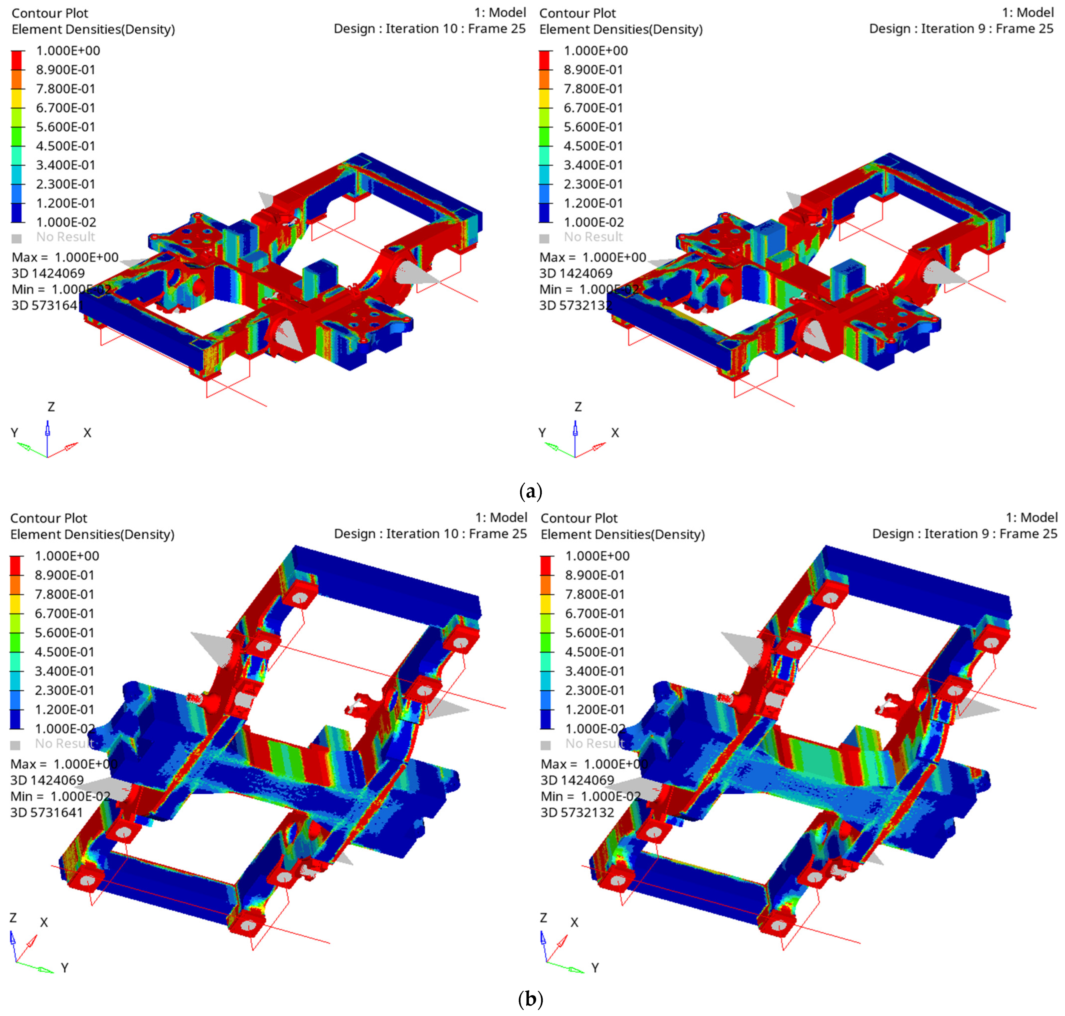
The results were analyzed based on two variables: element density distribution and computational times. Starting with the former, Figure 10a,b illustrates how the two distributions were highly consistent. Only minor differences were observed on the two lateral surfaces of the central crossbeam, with no consequential impact on the reconstruction of the final geometry. Material in that area would still be necessary due to the presence of attachments from various subsystems. Therefore, the two results could be considered effectively equivalent. Moving to computational times, a reduction of approximately 57% was observed between the full case and the reduced case, confirming the effectiveness of the proposed methodology.
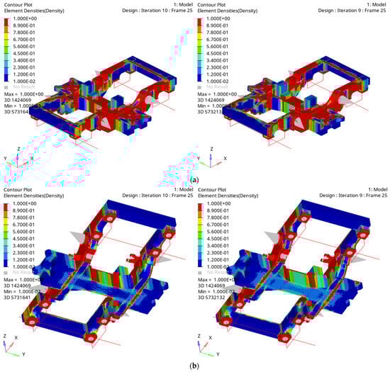
Figure 10.
(a,b) Element density distribution: complete analysis vs. reduced analysis.
3.3. Bogie Frame: Innovative Design and Verification
Once the optimization process was completed, the obtained result was used as a basis upon which to build the final design of the bogie frame. Manufacturing constraints allowed us to have a geometry already compliant with the sand-casting manufacturing process. The reconstruction began with the central cross beam, and then moved on to the two longitudinal beams, concluding with the details related to the supports and various interface zones. The structure was open in the lower area, allowing for the extraction of the main frame structure without the use of cores, which would have been very costly due to the size of the frame. Certainly, in this manufacturing process, some cores would be required around the secondary suspensions, as shown in the subsequent figures. In order to make the structure stiffer and more resistant, both in terms of flexural and torsional aspects, reinforcement sets were introduced throughout the lower area of the frame. Additionally, these were crucial to ensure as uniform a flow of molten material as possible. Furthermore, having an open structure downward, towards the rail, prevents the accumulation of external agents that could damage the metal structure. Figure 11a illustrates the final design obtained for the crossbeam, while Figure 11b shows that for the secondary suspension zone.
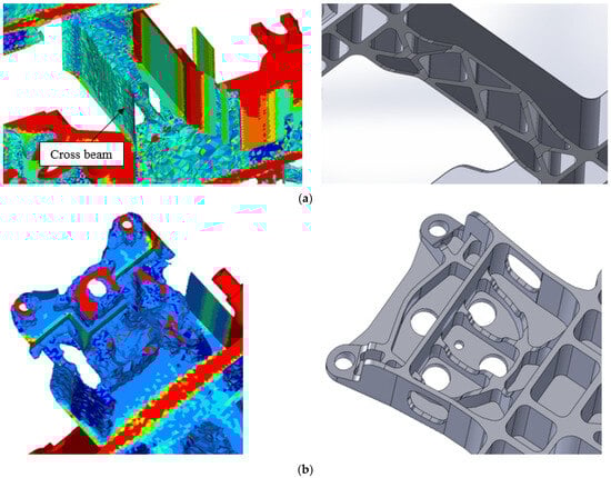
Figure 11.
Element density distribution from optimization vs. final bogie frame design: (a) cross beam zone, (b) secondary suspension zone.
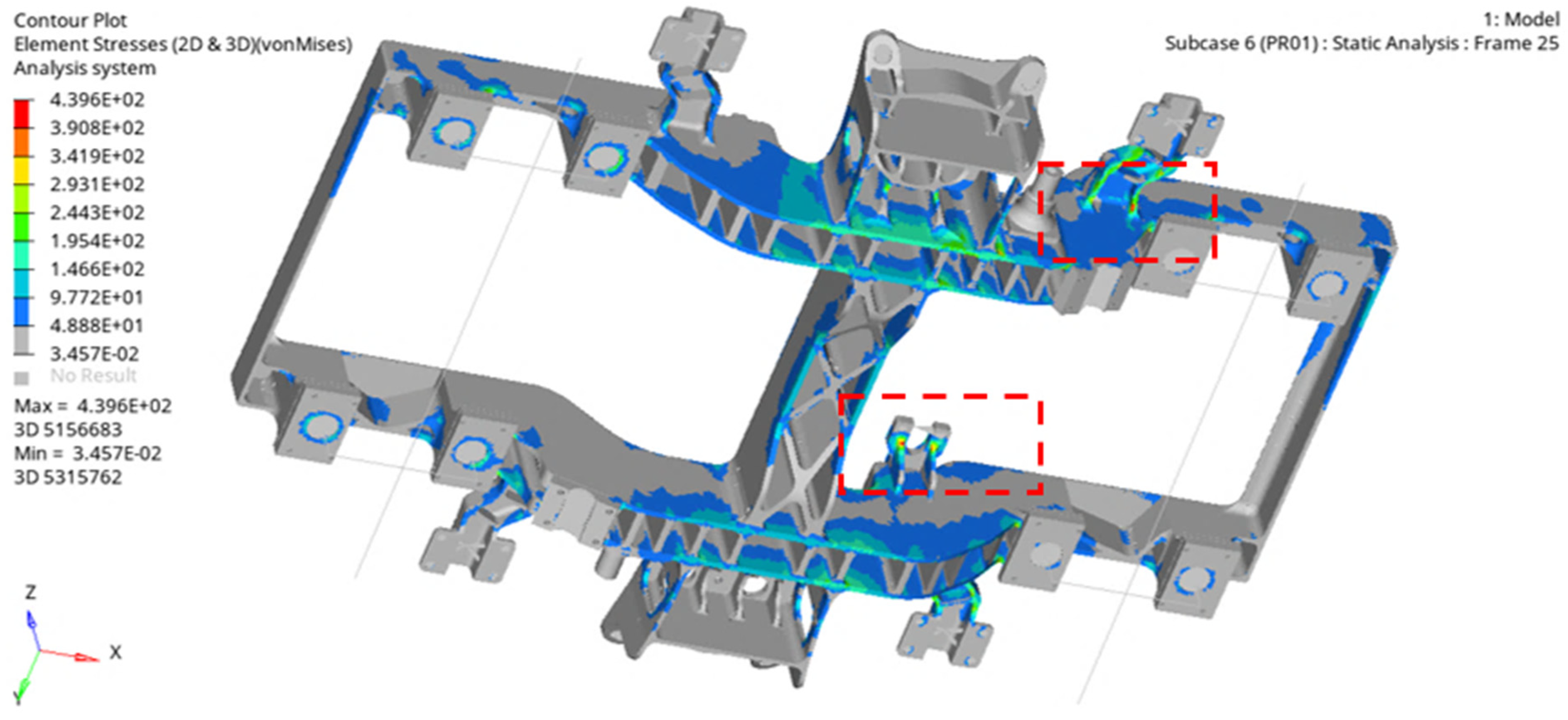
To conclude the activity, the innovative frame was tested both statically and under fatigue conditions in accordance with the reference standard [29], considering all the present load cases. The results were positive, and improvement was observed compared to the original frame, showing overall lower and better-distributed stresses. This once again confirms the effectiveness of the sensitivity analysis process. It allowed for a drastic reduction in computational times to achieve an innovative design for a complex component such as the one studied, ensuring at least the strength of the original frame under all loads considered for the structural verification of the system. Figure 12, in addition to a global view of the innovative design, shows the stress distribution obtained for case PR01, considered the most critical even from the sensitivity analysis. The maximum stress value reduced by 23% compared to the original case and was localized in a small area under two supports, as highlighted in the reference picture. In these cases, a consequent non-linear analysis would be required to investigate potential local material plasticization mechanisms that could be advantageous in terms of resistance. In addition, a general reduction in stress was observed for fatigue load conditions, as reported in Table 3. Utilization factor was calculated as the ratio between absolute principal stress (FEM) and permissible stress.

Figure 12.
Global view of the innovative design.
Table 3.
Fatigue analysis results.
4. Conclusions and Future Developments
In this article, the research activity was presented, involving the implementation of a complex structural topology optimization applied to a railway bogie frame. This included technological constraints aimed at achieving an innovative design potentially producible through sand-casting. The primary focus of the work centered on conducting a sensitivity analysis to identify the most critical load cases in terms of calculated numerical stress to speed up the design approach. This facilitated the identification of seven reference load cases for a subsequent comparative topology optimization. Positive results were obtained, with a 57% reduction in computational times to achieve a substantially identical design, affirming the validity of the sensitivity analysis. Ultimately, the proposed design resulting from the optimization process fully adhered to the initially imposed technological conditions. The final bogie frame design, featuring innovative shapes and geometries, could potentially facilitate a transition from a welding-based production process to one based on sand-casting, offering potential benefits in terms of time, costs, and mechanical performance. As future developments, accelerating the processes of structural topology optimization could allow them to become an integral part of the design process for new and complex components such as railway structures. Additionally, the potential to integrate mechanical fatigue as an optimization input could provide greater control over crucial outcomes in the field of railway engineering.
Author Contributions
Conceptualization, methodology, software and validation A.C.; review, supervision, project administration E.M. and A.R. All authors have read and agreed to the published version of the manuscript.
Funding
This research was funded by European Union Next GenerationEU (PIANO NA-ZIONALE DI RIPRESA E RESILIENZA (PNRR) MISSIONE 4 COMPONENTE 2, INVESTIMENTO 1.4 D.D. 1033 17/06/2022, CN00000023).
Data Availability Statement
The data presented in this study are available on request from the corresponding author.
Acknowledgments
This study was supported by the MOST Sustainable Mobility National Research Center and received funding from European Union Next GenerationEU (PIANO NAZIONALE DI RIPRESA E RESILIENZA (PNRR) MISSIONE 4 COMPONENTE 2, INVESTIMENTO 1.4 D.D. 1033 17/06/2022, CN00000023). All figures have been provided by Hitachi Rail S.p.A.
Conflicts of Interest
The authors declare no conflicts of interest.
References
- Billur, S.; Raju, G.U. Mass Optimization of Automotive Radial Arm Using FEA for Modal and Static structural Analysis. IOP Conf. Ser. Mater. Sci. Eng. 2021, 1116, 012113. [Google Scholar] [CrossRef]
- Viqaruddin, M.; Reddy, D.R. Structural optimization of control arm for weight reduction and improved performance. Mater. Today Proc. 2017, 4, 9230–9236. [Google Scholar] [CrossRef]
- Cavazzuti, M.; Baldini, A.; Bertocchi, E.; Costi, D.; Torricelli, E.; Moruzzi, P. High performance automotive chassis design: A topology optimization based approach. Struct. Multidiscip. Optim. 2011, 44, 45–56. [Google Scholar] [CrossRef]
- Pietropaoli, M.; Ahlfeld, R.; Montomoli, F.; Ciani, A.; D’Ercole, M. Design for Additive Manufacturing: Internal Channel Optimization. In Proceedings of the ASME Turbo Expo 2016: Turbomachinery Technical Conference and Exposition. Volume 5B: Heat Transfer, Seoul, Republic of Korea, 13–17 June 2016. [Google Scholar]
- Kirsch, K.L.; Thole, K.A. Experimental Investigation of Numerically Optimized Wavy Microchannels Created through Additive Manufacturing. J. Turbomach. 2018, 140, 021002. [Google Scholar] [CrossRef]
- Li, Z.; Zheng, X. Review of design optimization methods for turbomachinery aerodynamics. Prog. Aerosp. Sci. 2017, 93, 1–23. [Google Scholar] [CrossRef]
- Wang, B.; Wang, G.; Tian, K.; Shi, Y.; Zhou, C.; Liu, H.; Xu, S. A preliminary design method for axisymmetric turbomachinery disks based on topology optimization. Proc. Inst. Mech. Eng. Part C J. Mech. Eng. Sci. 2022, 236, 3313–3322. [Google Scholar] [CrossRef]
- Wang, B.; Wang, G.; Tian, K.; Shi, Y.; Zhou, C.; Liu, H.; Xu, S. Topology optimization and laser additive manufacturing in design process of efficiency lightweight aerospace parts. J. Phys. Conf. Ser. 2018, 1015, 52006. [Google Scholar]
- Lang, D.; Radford, D.W. Design Optimization of a Composite Rail Vehicle Anchor Bracket. Urban Rail Transit 2021, 7, 84–100. [Google Scholar] [CrossRef]
- Cho, J.G.; Koo, J.S.; Jung, H.S. A lightweight design approach for an EMU carbody using a material selection method and size optimization. J. Mech. Sci. Technol. 2016, 30, 673–681. [Google Scholar] [CrossRef]
- Koenig, J. Integral consideration of the lightweight design for railway vehicles. In Proceedings of the Young Researchers Seminar, Copenhagen, Denmark, 8–10 June 2011. [Google Scholar]
- Miao, B.; Luo, Y.; Peng, Q.; Qiu, Y.; Chen, H.; Yang, Z. Multidisciplinary design optimization of lightweight carbody for fatigue assessment. Mater. Des. 2020, 194, 108910. [Google Scholar] [CrossRef]
- Cascino, A.; Meli, E.; Rindi, A. Dynamic size optimization approach to support railway carbody lightweight design process. Proc. Inst. Mech. Eng. Part F J. Rail Rapid Transit 2023, 237, 871–881. [Google Scholar] [CrossRef]
- Cascino, A.; Meli, E.; Rindi, A. A strategy for lightweight designing of a railway vehicle car body including composite material and dynamic structural optimization. Railw. Eng. Sci. 2023, 31, 340–350. [Google Scholar] [CrossRef]
- Gersborg, A.R.; Andreasen, C.S. An explicit parameterization for casting constraints in gradient driven topology optimization. Struct. Multidiscip. Optim. 2011, 44, 875–881. [Google Scholar] [CrossRef]
- Harzheim, L.; Graf, G. A review of optimization of cast parts using topology optimization: I—Topology optimization without manufacturing constraints. Struct. Multidiscip. Optim. 2005, 30, 491–497. [Google Scholar] [CrossRef]
- Srivastava, P.K.; Shukla, S. Topology Optimization: Weight Reduction of Indian Railway Freight Bogie Side Frame. Int. J. Mech. Eng. 2021, 6. [Google Scholar]
- Yamamoto, M. Non-parametric optimization of railway wheel web shape based on fatigue design criteria. Int. J. Fatigue 2020, 134, 105463. [Google Scholar] [CrossRef]
- Xiu, R.; Spiryagin, M.; Wu, Q.; Yang, S.; Liu, Y. Fatigue life prediction for locomotive bogie frames using virtual prototype technique. Proc. Inst. Mech. Eng. Part F J. Rail Rapid Transit 2021, 235, 1122–1131. [Google Scholar] [CrossRef]
- Guo, F.; Wu, S.; Liu, J.; Zhang, W.; Qin, Q.; Yao, Y. Fatigue life assessment of bogie frames in high-speed railway vehicles considering gear meshing. Int. J. Fatigue 2020, 132, 105353. [Google Scholar] [CrossRef]
- Luo, R.K.; Gabbitas, B.L.; Brickle, B.V. Fatigue Life Evaluation of a Railway Vehicle Bogie Using an Integrated Dynamic Simulation. Proc. Inst. Mech. Eng. Part F J. Rail Rapid Transit 1994, 208, 123–132. [Google Scholar] [CrossRef]
- Lu, Y.; Zheng, H.; Zeng, J.; Chen, T.; Wu, P. Fatigue life reliability evaluation in a high-speed train bogie frame using accelerated life and numerical test. Reliab. Eng. Syst. Saf. 2019, 188, 221–232. [Google Scholar] [CrossRef]
- Luo, R.K.; Gabbitas, B.L.; Brickle, B.V. Dynamic stress analysis of an open-shaped railway bogie frame. Eng. Fail. Anal. 1996, 3, 53–64. [Google Scholar] [CrossRef]
- Mi, C.; Li, W.; Xiao, X.; Jian, H.; Gu, Z.; Berto, F. Lifetime assessment and optimization of a welded a-type frame in a mining truck considering uncertainties of material properties and structural geometry and load. Appl. Sci. 2019, 9, 918. [Google Scholar] [CrossRef]
- Zhou, W.; Zhang, G.; Wang, H.; Peng, C.; Liu, X.; Xiao, H.; Liang, X. Experimental fatigue evaluation of bogie frames on metro trains. Machines 2022, 10, 1003. [Google Scholar] [CrossRef]
- Wang, W.; Bai, J.; Wu, S.; Zheng, J.; Zhou, P. Experimental investigations on the effects of fatigue crack in urban metro welded bogie frame. Appl. Sci. 2020, 10, 1537. [Google Scholar] [CrossRef]
- Lucanin, V.J.; Simic, G.; Milkovic, D.D.; Cupric, N.U.; Golubovic, S.D. Calculated and experimental analysis of cause of the appearance of cracks in the running bogie frame of diesel multiple units of Serbian railways. Eng. Fail. Anal. 2010, 17, 236–248. [Google Scholar] [CrossRef]
- Yüksel, Ç. Microstructural analysis of EN-GJS-450-10 ductile cast iron via vibrational casting. China Foundry 2020, 17, 272–278. [Google Scholar] [CrossRef]
- EN 13749:2021; Railway Applications—Wheelsets and Bogies—Method of Specifying the Structural Requirements of Bogie Frames. Available online: https://standards.iteh.ai/catalog/standards/cen/06272177-7cda-4936-a237-125e4631de87/en-13749-2021 (accessed on 23 February 2024).
- Jameson, A. Gradient Based Optimization Methods. MAE Technical Report No (2057). 1995. Available online: http://aero-comlab.stanford.edu/Papers/jameson.gbom.pdf (accessed on 23 February 2024).


Disclaimer/Publisher’s Note: The statements, opinions and data contained in all publications are solely those of the individual author(s) and contributor(s) and not of MDPI and/or the editor(s). MDPI and/or the editor(s) disclaim responsibility for any injury to people or property resulting from any ideas, methods, instructions or products referred to in the content. |
© 2024 by the authors. Licensee MDPI, Basel, Switzerland. This article is an open access article distributed under the terms and conditions of the Creative Commons Attribution (CC BY) license (https://creativecommons.org/licenses/by/4.0/).