Abstract
The method of improving a two-section mainline diesel locomotive by using energy storage in the traction system is considered. A mathematical model was developed to study the movement of a diesel locomotive based on the recommendations and provisions of the theory of locomotive traction. For this purpose, the movement of a diesel locomotive as part of a train along a given section of a track was studied. It was determined that the use of an energy storage device on a diesel locomotive will allow up to 64% of the energy spent on train traction to accumulate. The use of energy storage in the accumulator during electrodynamic braking ensured a reduction in fuel consumption by about 50%, regardless of the options for equipping the traction system of the diesel locomotive with an energy accumulator. It is established that regardless of the options for equipping the traction system of the diesel locomotive with an energy storage device, the indicators characterizing the degree of use of the diesel engine do not change. These research results can be used in works devoted to the improvement of the control system of energy exchange between the accumulator and traction engines of diesel locomotives.
1. Introduction
Three international pan-European railway transport corridors—No. 3 (Gdansk–Odesa (Baltic Sea, Black Sea)), No. 5 (Europe–Caucasus–Asia (TRACESA)), and No. 9 (Europe–Asia)—run through the territory of Ukraine. Also, Ukrainian railways through river ports are tangential to pan-European corridor No. 7, which runs along the Danube [1,2]. In 2023, an agreement was reached on the creation of a 1520 mm gauge railway corridor between Ukraine and Lithuania [3]. The railway lines of the active transport corridors, as well as the main highways, are electrified. This ensures a low cost of transportation and the potential for further development of transit transportation [4]. At the same time, parts of the railway lines that transport goods to stations located on the lines of transport corridors, ports, logistics terminals, etc., are served by diesel locomotives. The insufficient volumes of these vehicles make it impractical to electrify such areas, even under conditions of constant growth in the cost of fuel and lubricants. Therefore, it is considered that, for such lines, it is necessary to use modern or modernized diesel locomotives; as a result, a reduction in operating costs and the elimination of the negative impact on the environment will be achieved.
To update the fleet of mainline freight diesel locomotives, TE33A “Tryzub” diesel locomotives were purchased, which are a version of the Evolution ES44ACi diesel locomotive adapted for 1520 mm gauge [5,6]. The advantages of the new diesel locomotive are reduced consumption of fuel and lubricants, increased service intervals, lower harmful emissions, improved working conditions of the locomotive crew, etc. Also, the new diesel locomotive has significantly higher traction characteristics compared to existing diesel locomotives, which makes it possible to increase the efficiency of the transportation process.
Another option for renewal is the modernization of diesel locomotives, which is widely used to improve the locomotive fleet. Its advantage is a lower cost compared to the purchase of a new locomotive. The diesel locomotive fleet of state railways and private carriers in the Baltic States and Eastern Europe has been updated through modernization. In 2011, the domestic railway operator JSC “Ukrzaliznytsia” modernized M62 diesel locomotives using General Motors equipment [7]. The PrJSC Poltava Diesel Locomotive Repair Plant modernized 2TE10M diesel locomotives using the SuperSkid power module from GE [8]. Modernization ensured a reduction in fuel consumption, reduced oil consumption, etc. However, due to the preservation of the original traction electric motors, the traction properties of diesel locomotives have hardly improved.
The method of updating the fleet of locomotives is to reduce operating costs, a significant part of which is the cost of fuel and lubricants. The key here is to ensure the use of modern diesel engines, which use less fuel compared to older models. The use of traction electric drives and auxiliary electric drives, which have increased energy efficiency, also contribute to reducing fuel consumption. A reserve for further reductions in fuel consumption is the accumulation of energy during electrodynamic braking and its use in traction modes. This technology is being researched by many research centers and companies [9].
In existing studies, two approaches to the use of energy storage devices are proposed [9,10,11]. The first is that the energy storage is integrated into the diesel generator set, and they can work on a common load [12,13,14]. The second involves energy storage that is placed on a separate section and interacts only with the traction drive of this section [15,16,17].
The results of the study in accordance with the first option of adding an energy storage device to the traction system can be found in [10]. In this paper, through modeling, it is established that the use of an energy storage device leads to a reduction in fuel consumption by up to 16.5%, and harmful diesel emissions are also reduced. In [11], it is shown that the potential energy saving during the movement of the studied train is 23.87%. Taking into account the construction of the optimal cost criterion of the life cycle of the drive in LTO elements, the savings will be 15.67%.
Research on the application of energy storage is applied to many types of rail transport [18,19,20]. In [21], a shunting locomotive is studied when performing removal work. It is shown that when using an energy storage system in the traction system, the reduction in fuel consumption is 20.57% without the use of recuperation and 25.64% in the case of using energy storage. In [22], the results of the operation of the Ki-Ha E200 rail bus are given, the use of a storage device on which saved 10% of fuel. Ref. [23] provides data on the reduction in energy consumption by a passenger diesel locomotive for various operating conditions. The reduction in energy consumption is 47.52% of the total energy consumption.
An alternative option is the use of a separate booster section in which the energy storage is located [17,24,25]. Operational studies of the FLXdrive battery locomotive are being conducted in the USA, the use of which as part of a multi-section diesel locomotive made it possible to save 11% of fuel [15]. The research results on a locomotive with a booster section equipped with an energy store are given in [17,26]. According to the simulation results, it was established that fuel consumption by locomotives from energy storage is reduced by 12.40% when using inertial storage and 20.65% when using batteries. In [25], it was found that the use of a booster section with an energy store allows fuel consumption to be reduced by 22–30%.
Thus, the results of theoretical and experimental studies show the possibility of eliminating the consumption of fuel and energy resources when using energy accumulators on mainline freight locomotives. The limitation of the obtained results is that they were obtained for a specific type of diesel locomotive under specific operating conditions. This makes it impossible to extend them to other conditions, and therefore, there is a need for new studies on specific types of locomotive, train, and route. To determine the effectiveness of the use of energy storage on rolling stock, indicators characterizing the costs of operating a serial rolling stock without energy storage and a hypothetical modernized rolling stock with energy storage are compared [10,23]. As a rule, fuel consumption is taken as an indicator. In more advanced calculations, economic indicators and combinations of indicators that take into account various aspects of locomotive operation are used as efficiency criteria [11,16]. Considering the above, it is necessary to carry out research to determine the effectiveness of energy storage on domestic rolling stock.
The aim of this research is to assess the potential of energy saving when using energy storage devices on mainline diesel locomotives on the railways of Ukraine.
The following tasks were performed as part of the assigned work:
- -
- A mathematical model of the movement of the main diesel locomotive is developed in Section 2;
- -
- The movement of a diesel locomotive as part of a train is modeled for the following options in Section 3: movement with a serial diesel locomotive; movement with a diesel locomotive as part of one diesel and booster section with an energy accumulator (energy exchange is carried out only with the traction system of the booster section); movement with a diesel locomotive as part of one diesel and booster section with an energy accumulator (energy exchange is carried out with the traction systems of the diesel and booster sections);
- -
- The obtained results are discussed in Section 4;
- -
- Conclusions are drawn in Section 5.
2. Development of a Mathematical Model of Train Movement
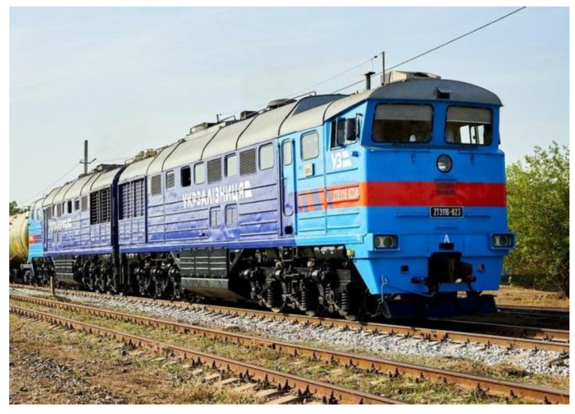
The most common locomotives on Ukrainian railways are the 2TE116 freight locomotives manufactured by PJSC “Luhanskteplovoz” (Luhansk, Ukraine) (Figure 1). The basic form is a two-section diesel locomotive. The design of the locomotive is described in [27,28,29].
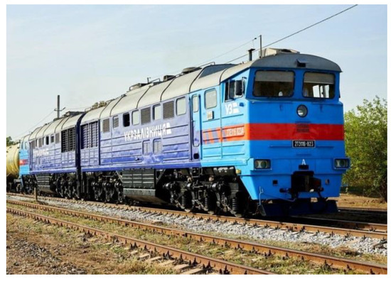
Figure 1.
General appearance of the 2TE116 diesel locomotive (photo [30]). Non-English word means an element of the locomotive livery, which contains the name of the company in Ukrainian.
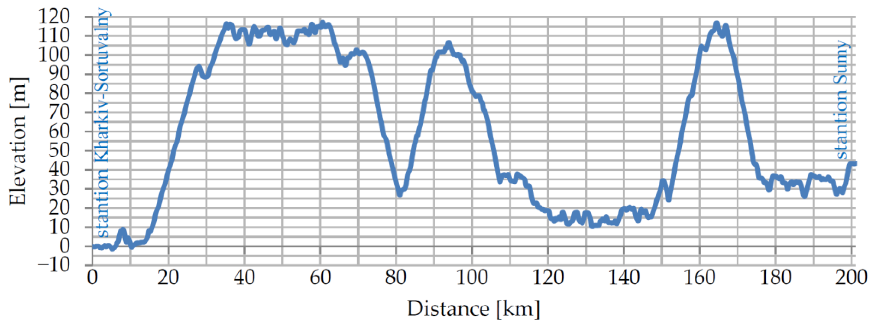
This study aimed to determine the movement parameters of the mainline diesel locomotive as part of a train journey carried out in the section between the Kharkiv-Sortuvalnyi and Sumy stations in both directions. The length of the section is 201 km; the profile of the route is shown in Figure 2.
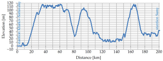
Figure 2.
Path profile (created by the authors).
An analysis of works devoted to the research of new technologies on rolling stock shows that mathematical modeling is used in the initial stages [16,19]. Modeling is important in creating modern equipment for vehicles [31,32] and rail transport systems in general [32,33,34]. Mathematical modeling is widely used, in particular, for the study of rolling stock [35,36,37], traction power supply systems [38,39,40], infrastructure objects [41,42,43], traffic safety assessment [44,45], transportation process management [46], etc. The priority is mathematical modeling that does not require the production of physical prototypes of equipment and systems.
Mathematical modeling is used in research devoted to the application of energy storage on railway rolling stock [16,21]. This makes it possible to assess the expediency and efficiency of energy storage applications. For this purpose, performance indicators of a serial locomotive without energy storage and a hypothetical locomotive equipped with energy storage are compared [16,19,25].
The mathematical modeling of train movement involves determining movement parameters: duration, speed, the consumption of energy resources, etc. A mathematical model was developed to study the movement of a mainline locomotive based on the recommendations and provisions of the theory of locomotive traction [47]. It is accepted that the train was viewed as a chain of rigid bodies connected rigidly [48].
The mathematical model of train movement is described by the following system of equations [48,49]:
where ξ—coefficient taking into account the units of measurement;
- v—train speed;
- t—time;
- S—path;
- ρ—coefficient that takes into account the rotation of the parts of the locomotive subframe;
- fL—specific traction force of the locomotive in traction or electrodynamic braking mode;
- wL—specific resistance force of the locomotive movement;
- wW—specific force of resistance to movement of wagons;
- b—specific braking force of pneumatic brakes.
The specific tangential force of the locomotive in the mode of traction or electrodynamic braking was determined in accordance with the expression
where FL—traction force of the locomotive in traction or electrodynamic braking mode;
- MLk—mass of the locomotive section;
- s—the number of locomotive sections;
- MWj—mass of the wagon;
- n—the number of wagons.
The specific resistance to movement of the locomotive and wagons was determined in accordance with the expression
where wL—main specific resistance of movement;
- wi—additional specific resistance to movement from a slope;
- wr—additional specific resistance of movement from movement along a curve;
- ws—additional specific resistance during train movement.
The main specific resistance during locomotive movement was determined as follows [47]:
The first equation of the system corresponds to the traction mode, and the second to the coasting and braking modes.
The main specific resistance of four-axle wagons on semi-wagons was determined as [48]
where qo—axle load;
- g—acceleration of free fall.
With the calculated weight of the loaded wagon of 84 tons, the axle load is 21 tons.
In the case of the movement of an empty wagon (or with an axle load of less than 6 tons), the main specific resistance was calculated in accordance with the following expression [48]:
Additional resistance when moving on a slope was determined as
where i—axle load.
Let us determine the resistance from movement along a curved section of the track in accordance with the expression [48]
where R—radius of the curve.
Additional resistance during displacement was determined in accordance with the expression [48]
where q—load on the axis of the rolling stock unit.
The control system, which sets the force of traction and braking, functions in such a way as to maintain the permissible speed of movement on the site. Stop braking is carried out at the end of the movement on a section that is 1500 m long.
The energy that is actually produced by the diesel during movement in traction modes is
where i—position number of the driver controller in traction mode;
- gi—specific fuel consumption at the i-th position of the driver’s controller;
- τi—total duration of diesel operation at the i-th position of the driver’s controller;
- g0—specific fuel consumption in idle mode;
- τ0—total duration of diesel engine operation in idling mode;
- N—total number of driver controller positions.
For additional evaluation of the use of the power plant, the following indicators are used.
The coefficient of use of the installed diesel power, which characterizes the completeness of the consumption of the installed (nominal) power of the diesel generator set when moving under load, is defined as [50,51]
where EF—energy actually produced by the diesel engine during movement in traction mode;
- ED—theoretical value of the energy that a diesel engine could produce when operating at rated power during movement.
The energy actually produced by the diesel engine during movement in traction mode was determined as
where Pi—power of the diesel engine at the i-th position of the driver’s controller.
The theoretical energy value is calculated according to the expression
where PN—nominal power of the diesel engine.
The load factor of the diesel engine over time [50] was determined as
where T1—total duration of work under load in traction mode;
- T2—total duration of coasting mode during movement along the section;
- T3—total duration of braking mode, including electrodynamic braking.
The theoretical coefficient of energy accumulation was determined by the expression
where AB—work “on the wheel” of braking forces;
- AT—work “on the wheel” of traction forces;
- ηR—average value of the efficiency of the traction system and the energy storage system during accumulation;
- γAUX—share of energy consumed by auxiliary systems in electrodynamic braking mode;
- γB—share of energy that is utilized by other braking systems during braking.
The coefficients ηR, γAUX, and γB can be reliably determined based on the results of calculations of parameters of motion processes. Let us consider it expedient to accept the following values for estimation calculations:
- -
- The average value of the efficiency of the traction system and the energy storage system during accumulation is 0.9;
- -
- The share of energy consumed by auxiliary systems in electrodynamic braking mode: γAUX = 0.05;
- -
- The share of energy that, during braking, is utilized by other braking systems: γB = 0.06.
Then, Expression (15) takes the form
The actual accumulation coefficient was determined in accordance with the expression
where AE—energy that was actually accumulated in the accumulator.
3. Results of Train Motion Simulation
3.1. Modeling the Movement of a Train with a Serial Diesel Locomotive (Option 1)
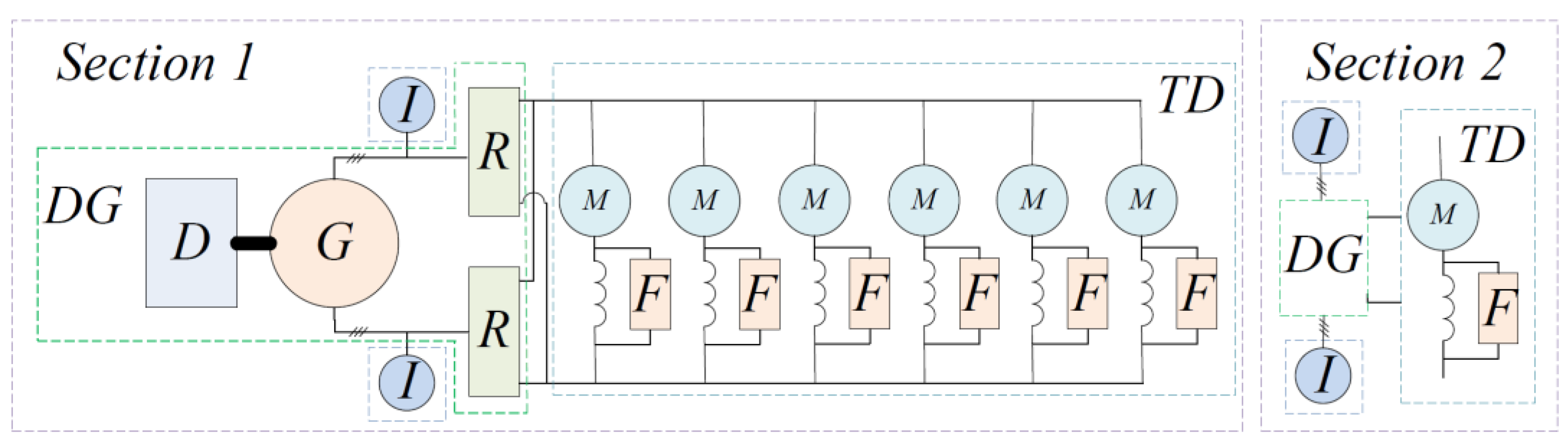
The electric locomotive uses alternating current–direct current power transmission. The diesel generator has a traction synchronous generator in its composition, which feeds an uncontrolled rectifier. DC traction motors with series excitation are powered from the rectifier. The regulation of electric motors is carried out by changing the voltage on their armatures, for which the excitation current of the traction generator is changed. In addition, shunting of the excitation windings of traction electric motors is used, for which field weakening resistors and appropriate contact equipment are used. A simplified structural diagram of the traction system of a serial diesel locomotive is shown in Figure 3. The traction systems of sections 1 and 2 are identical.
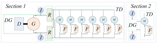
Figure 3.
Simplified structural diagram of the traction system of the 2TE116 diesel locomotive.
In Figure 3, the following designations are used: DG—diesel genset with non-controlled rectifier, TD—traction electric drive, D—diesel engine, G—traction synchronous generator, R—non-controlled rectifier, M—DC traction electric motors, F—field weakening resistors and their switching devices, and I—auxiliary induction electric motors of equipment-cooling motor fans.
Figure 4 shows the traction characteristics of the 2TE116 serial diesel locomotive in the composition of two identical sections.
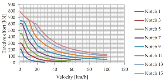
Figure 4.
Traction characteristics of the 2TE116 diesel locomotive at odd positions of the driver’s controller.
Table 1 shows fuel consumption on hyperbolic sections of traction characteristics.

Table 1.
Characteristics of fuel consumption by diesel locomotive 2TE116 in the composition of two sections.
Calculations were made for the permissible speed of 60 km/h, which corresponds to the actual speeds of freight trains on the section. For the calculation, a train weighing 4056 tons with forty-five loaded wagons (this corresponds to the weight standard for a 2TE116 diesel locomotive) and 1311 tons with forty-five empty wagons was accepted. The mass of the diesel locomotive is 276 tons. The simulation was carried out while moving in both directions. The results of calculations are given in Table 2.
Table 2.
Results of the calculation of traffic parameters on the Kharkiv-Sortuvalnyi–Sumy section.
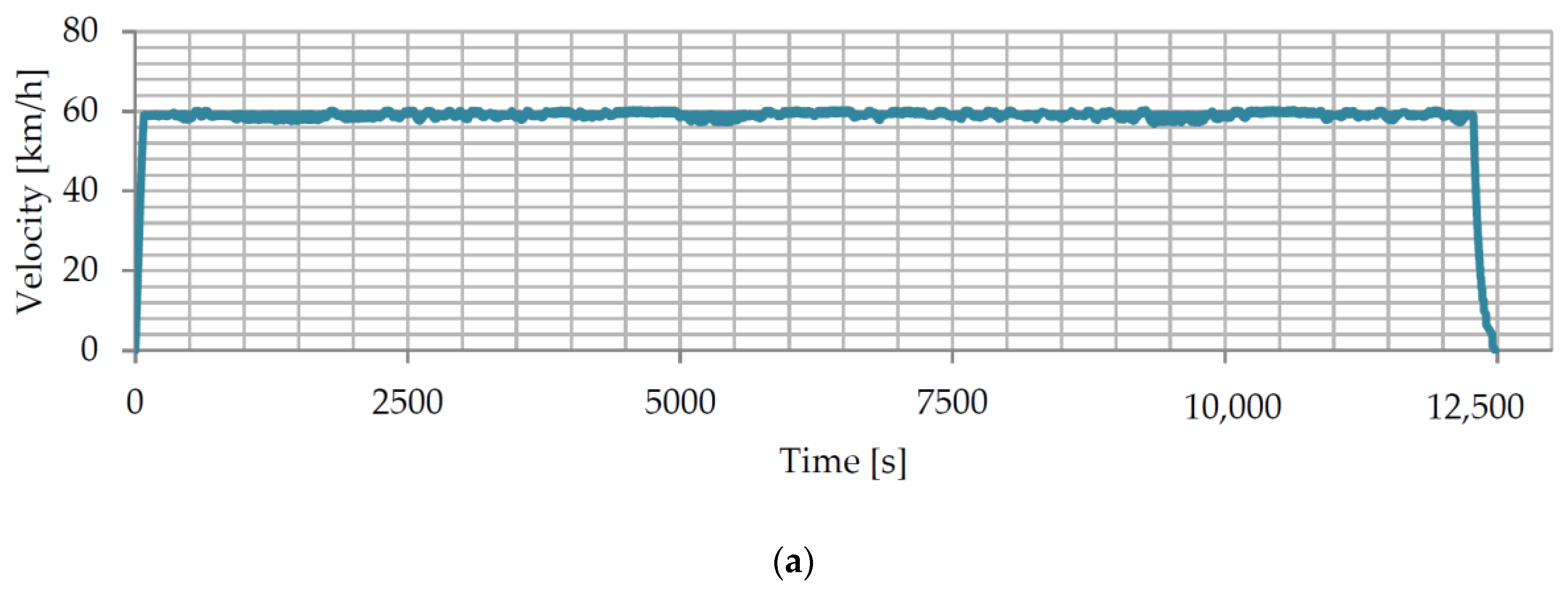
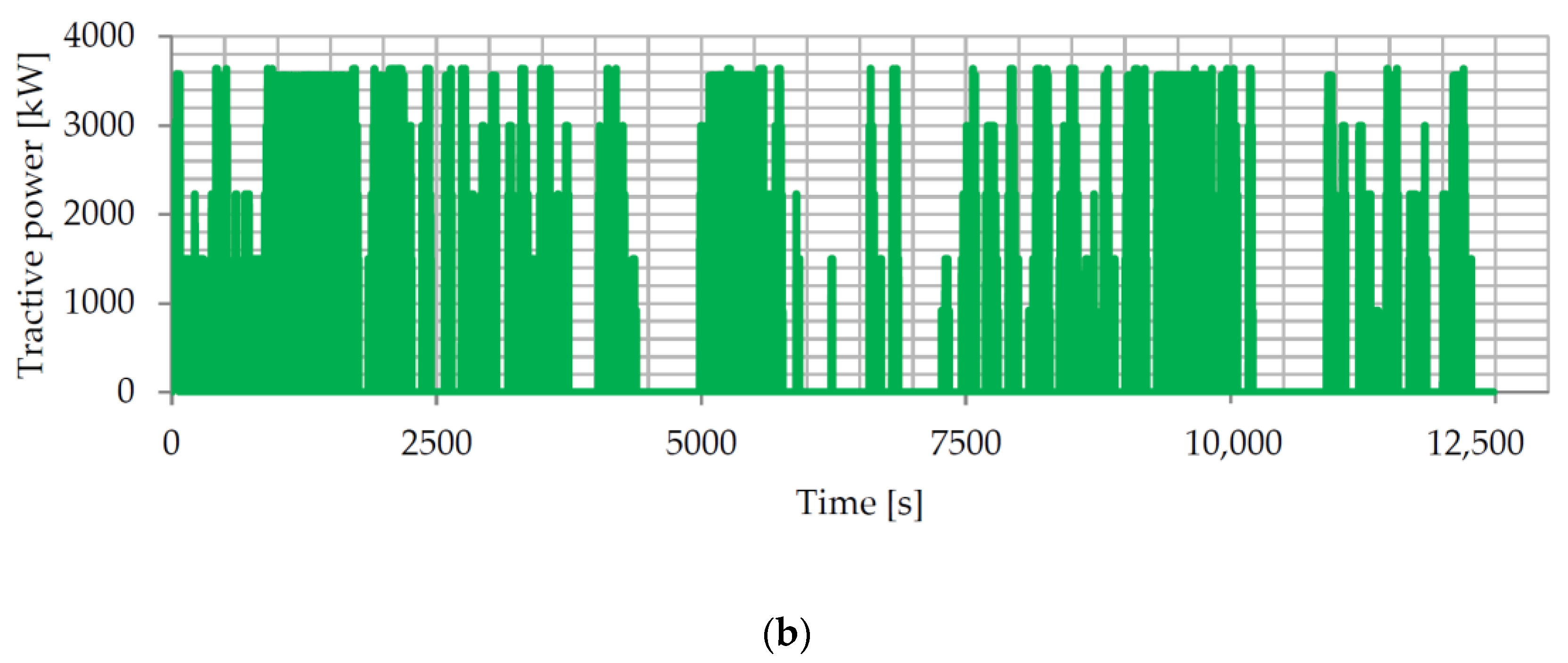
From Figure 5 and Figure 6, it can be seen that the movement is carried out at a permissible speed. For loaded wagons, there is a decrease in speed when moving on climbs; the tangential power mostly corresponds to the nominal power of the diesel locomotive. When moving with empty wagons, the tangential power takes intermediate values according to the locomotive’s traction characteristics. For the reverse direction—from the Sumy station to the Kharkiv-Sortuvalnyi station—the speed and traction force dependences are similar to those shown in Figure 5 and Figure 6.
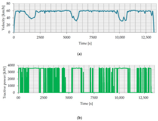
Figure 5.
Time dependence of the speed (a) and tangential power of the diesel locomotive (b) during the movement of a train with loaded wagons from the Kharkiv-Sortuvalnyi station to the Sumy station.
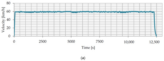
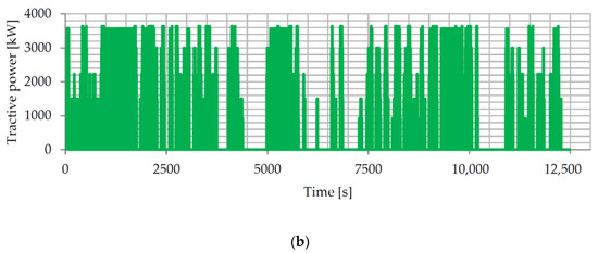
Figure 6.
Time dependence of the speed (a) and tangential power of the diesel locomotive (b) during the movement of a train with empty wagons from the Kharkiv-Sortuvalnyi station to the Sumy station.
The data in Table 2 shows that, for movement with loaded wagons, the coefficient of use of the installed diesel power is 0.87–0.88, and the loading coefficient of the diesel engine over time is 0.48–0.5. When moving with empty wagons, the utilization factor of the installed diesel power is 0.52, and the load factor of the diesel engine over time is 0.41–0.43. Larger values of the coefficient of use of the installed capacity of the diesel engine correspond to more difficult driving conditions with loaded wagons. However, the diesel load factor changes insignificantly over time when the mass of the train changes.
The theoretical coefficient of energy accumulation is 0.426–0.648. That is, 42.6% to 64.8% of the energy spent in traction mode can be stored in the on-board energy storage system and can be reused in traction modes. This will ensure a reduction in fuel consumption and increase the service life of the diesel engine. To implement this, the traction system of the diesel locomotive must include an energy storage system.
3.2. Modeling the Movement of a Train with a Diesel Locomotive as Part of Diesel Sections and a Booster Section with Energy Storage (Option 2)
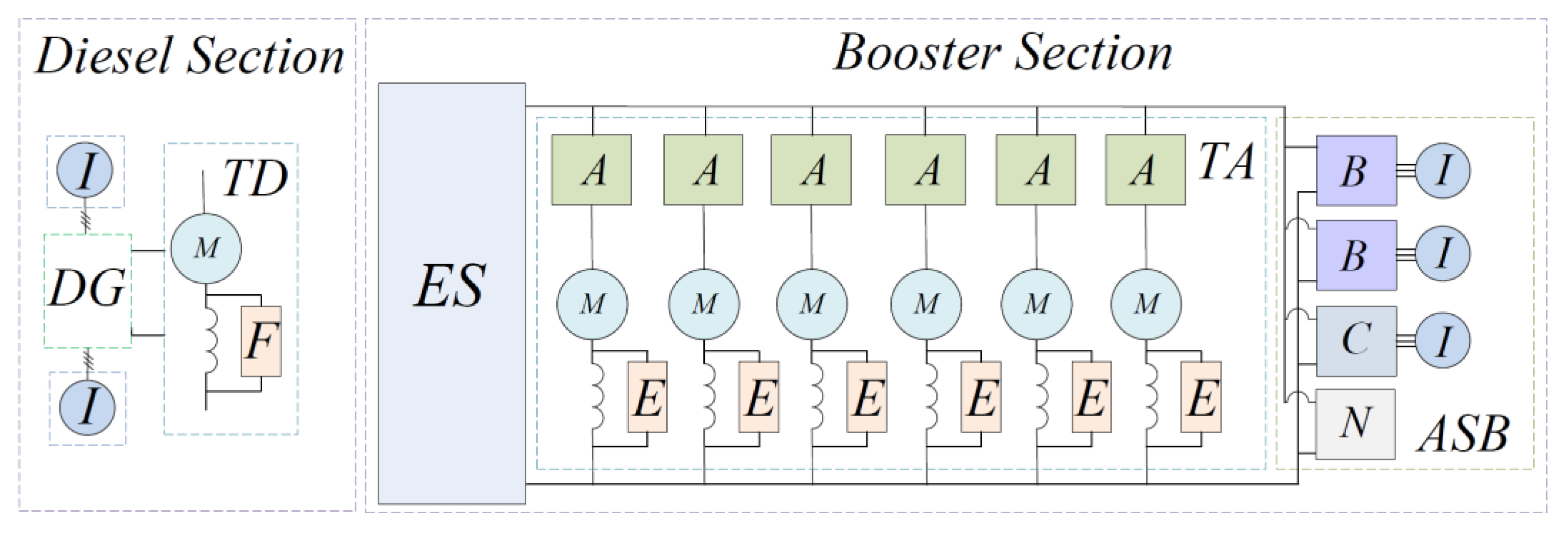
Studying the movement of a train with a serial diesel locomotive showed the presence of a significant potential for accumulating energy in the on-board storage device. The option was studied when one of the sections of the diesel locomotive was converted and a storage device was installed on it. For this purpose, it is necessary to use semiconductor converters for powering and controlling electric motors, which, in this case, will work with current pulsations [52,53]. A possible version of the construction of the traction system of the locomotive is shown in Figure 7 (the diesel section does not change; its traction system is shown in Figure 3).
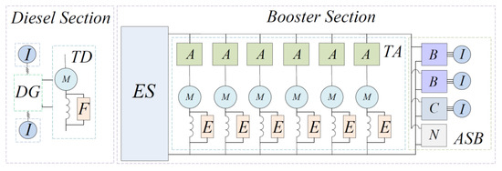
Figure 7.
Structural diagram of the traction system of diesel locomotive with isolated booster section.
In Figure 7, the following designations are used: TA—traction electric drive with semiconductor converter, ES—energy accumulator, A—semiconductor converter of the armature circuit, E—semiconductor excitation regulator, ASB—auxiliary system of the booster section, B—semiconductor power converter of cooling motor fans of traction electric motors, C—semiconductor power converter of the compressor unit, N—semiconductor power converter of additional systems of the booster section, and I—auxiliary induction electric motors. Other designations are shown in Figure 3.
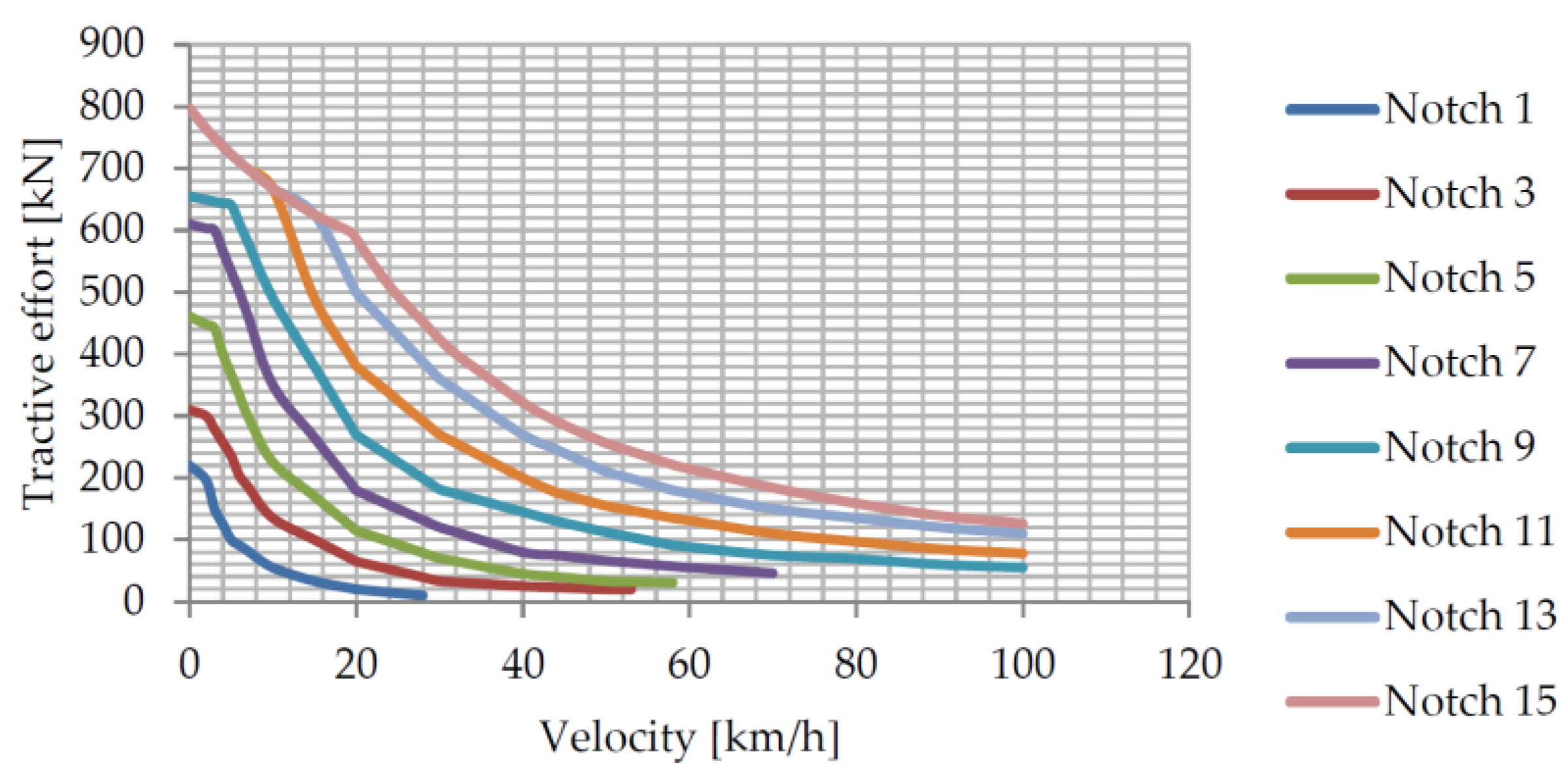
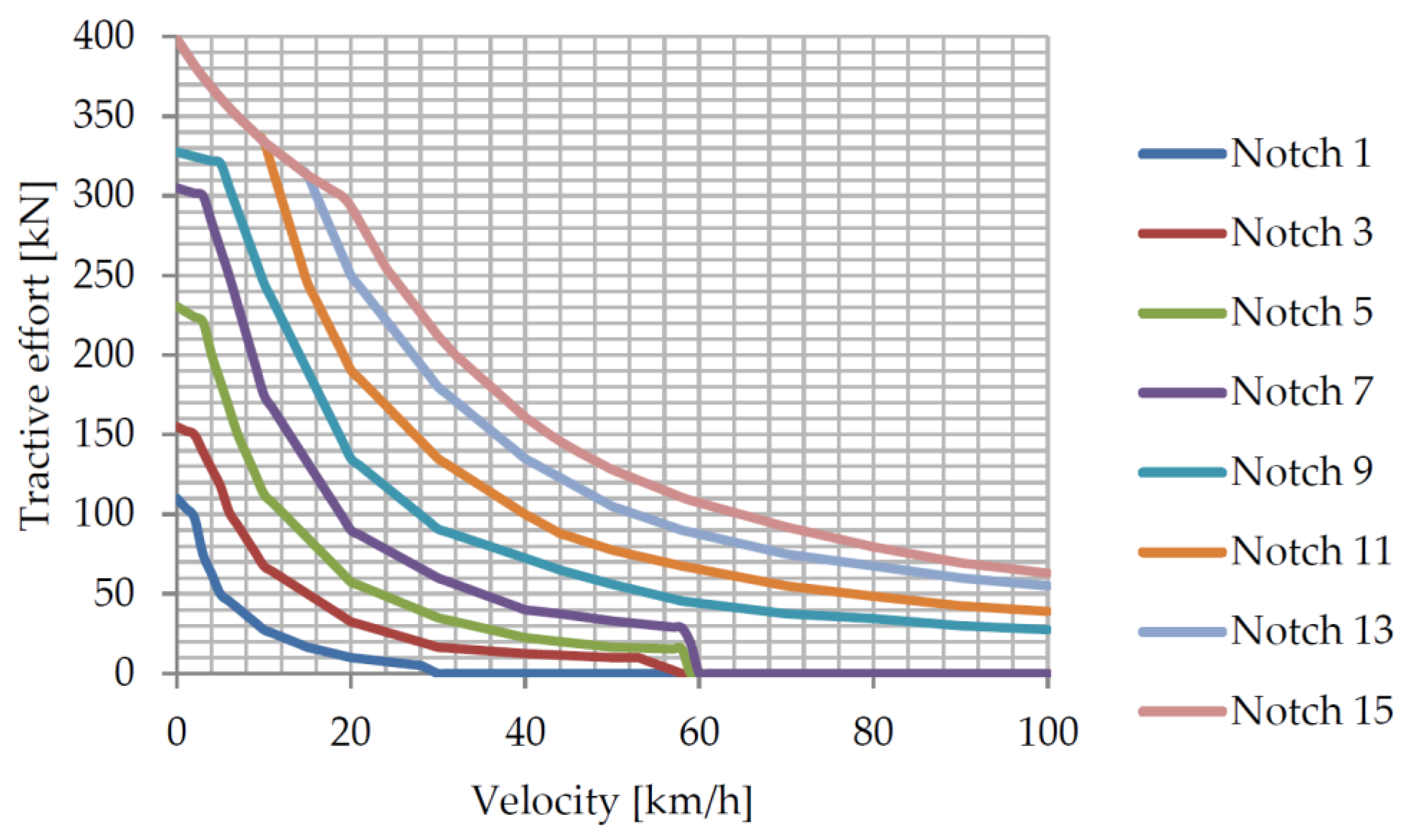
For modeling purposes, it is assumed that the booster section with energy storage has traction and braking characteristics identical to the characteristics of the diesel section. The traction characteristics of the booster section are shown in Figure 8.
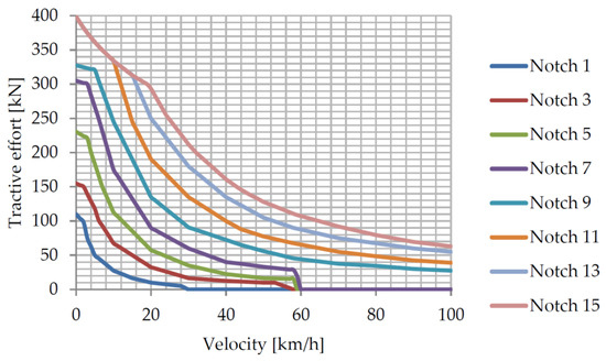
Figure 8.
Traction characteristics of the booster section of the diesel locomotive.
Since, in the studied version of the locomotive, the diesel generator set remains only on the diesel section, the fuel consumption of the locomotive will decrease (Table 3).
Table 3.
Fuel consumption by diesel section.
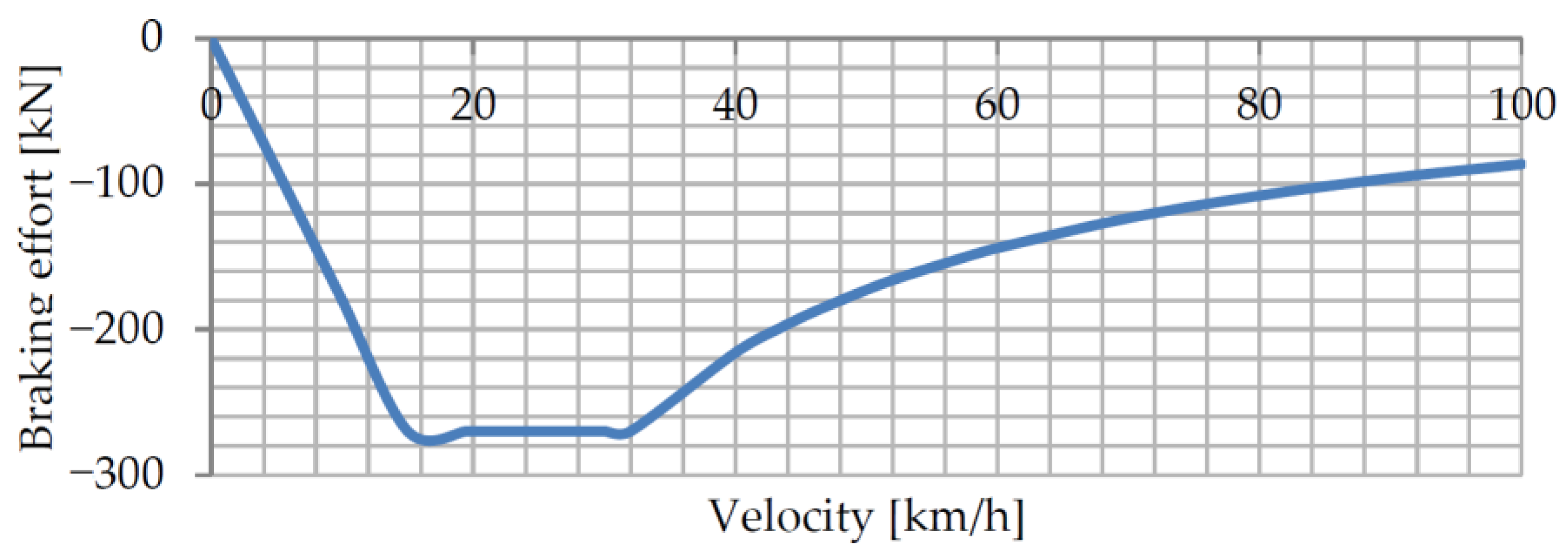
The limiting braking characteristic of one section of the diesel locomotive is shown in Figure 9.

Figure 9.
Limiting braking characteristic of one section of a diesel locomotive.
With electrodynamic braking, the operation of both sections is possible at any point within the braking area [54]. On the accelerated section, this is ensured by appropriate control of the traction converters. To implement electrodynamic braking, braking resistors must be installed on the diesel section. If the section is equipped with an automatic rheostat brake control system, it is also possible to operate in any mode corresponding to the points “inside” the area that are limited by the limiting braking characteristic. The scheme of the traction wheels in the braking mode corresponds to the traditional schemes that are used on diesel locomotives with rheostat braking and are not shown here. It should be noted that for cooling the traction electric motors in the rheostat braking mode, an increase in the engine speed is necessary. There are no data on fuel consumption in such modes, so in the simulation, it is assumed that the fuel consumption corresponds to the mode of operation at the zero position of the driver’s controller (although the real fuel consumption will be greater).
Table 4 shows the results of calculations during the movement of a diesel locomotive, which consists of serial diesel and booster sections with energy storage. The simulation is carried out under the same conditions as in option 1.
Table 4.
Results of calculation of train movement parameters.
The calculation of energy exchange processes was carried out as follows [55,56].
The power, which is exchanged by the storage unit with the traction electric drive, was determined as
where PkB—tangential power of the booster section;
- ηTD—total efficiency of traction electric drive (accepted efficiency equal to 0.9 for traction mode and electrodynamic braking mode);
- PauxB—power of auxiliary systems of the booster section (taken equal to 150 kW).
The energy change in the accumulator was determined by the expression
where ηES—energy storage efficiency (in charging and discharging modes, this is equal to 0.9);
- Δt—duration of the charging (discharging) process.
Table 4 shows that the parameters correspond to the traffic parameters with a serial diesel locomotive. Minor differences can be explained by modeling errors. Table 4 shows that the actual coefficients of energy accumulation are approximately half as much as the theoretical values. This is explained by the fact that energy is accumulated only from the traction electric drive of the booster section. The diesel section does not provide energy for the accumulator. However, fuel consumption was reduced by approximately half. That is, the use of an energy storage device made it possible to halve the consumption of fuel, which is consumed directly during the movement of a diesel locomotive with a train along the section.
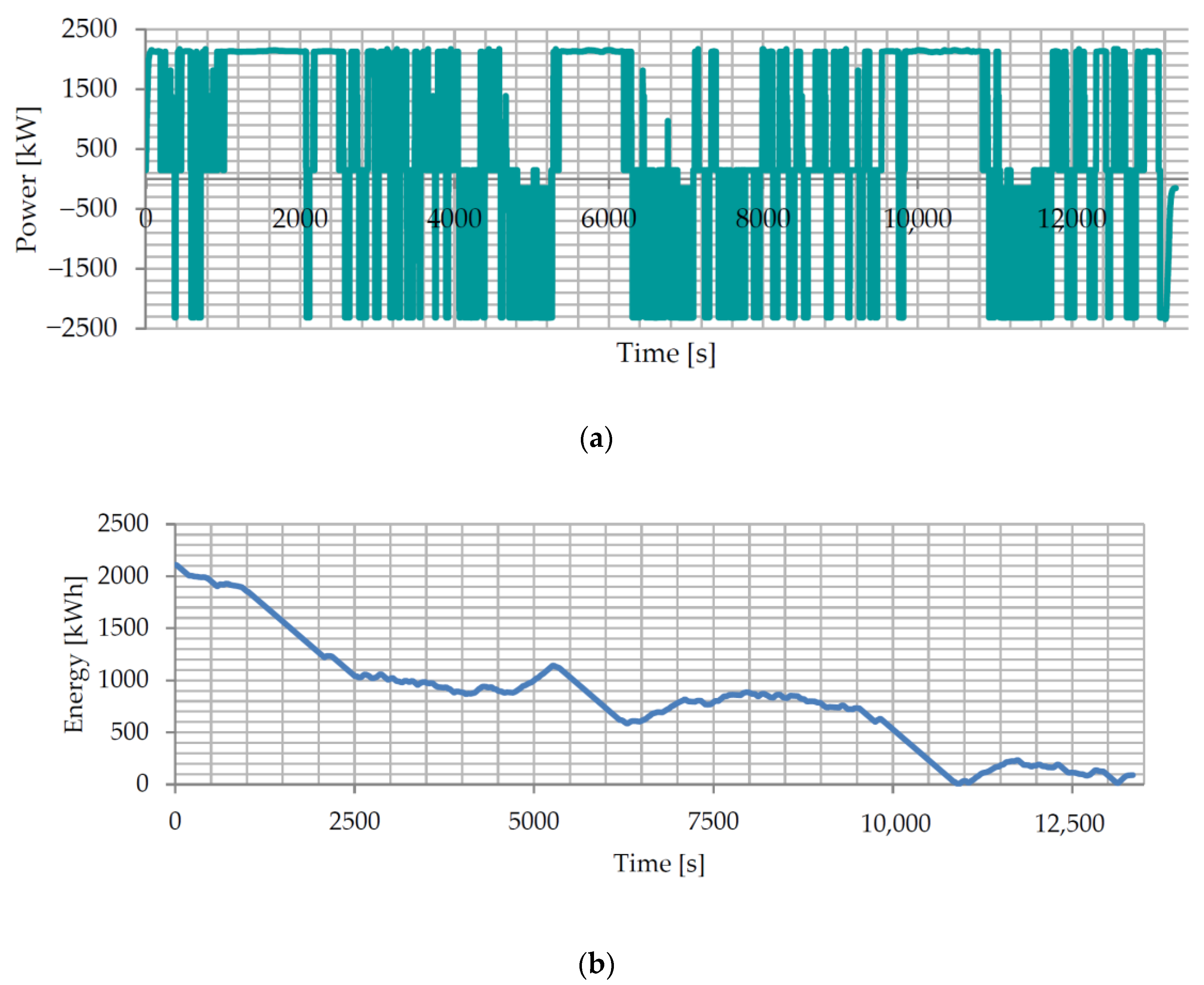
Figure 10 and Figure 11 show the time dependences of power and energy changes in the accumulator. The motion curves (speed, tangential power) are identical to the curves obtained during the movement of a train with a basic diesel locomotive (Figure 5 and Figure 6). Table 4 shows the results of calculating the movement parameters for the studied option.
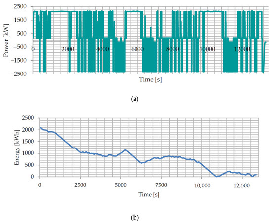
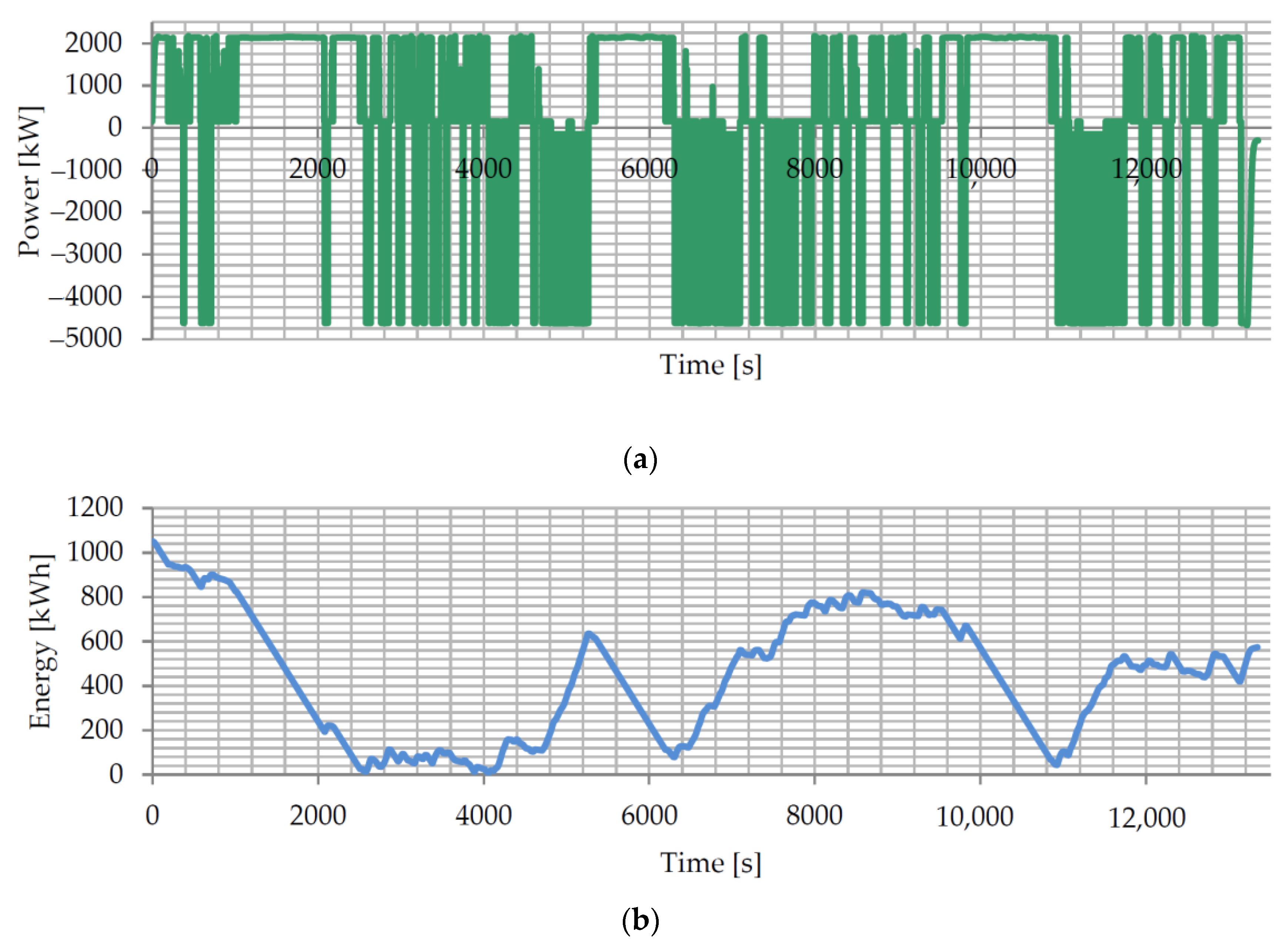
Figure 10.
Time dependences of power (a) and energy change (b) of the accumulator when moving from Kharkiv-Sortuvalnyi station to Sumy station with loaded wagons.
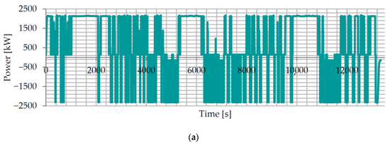

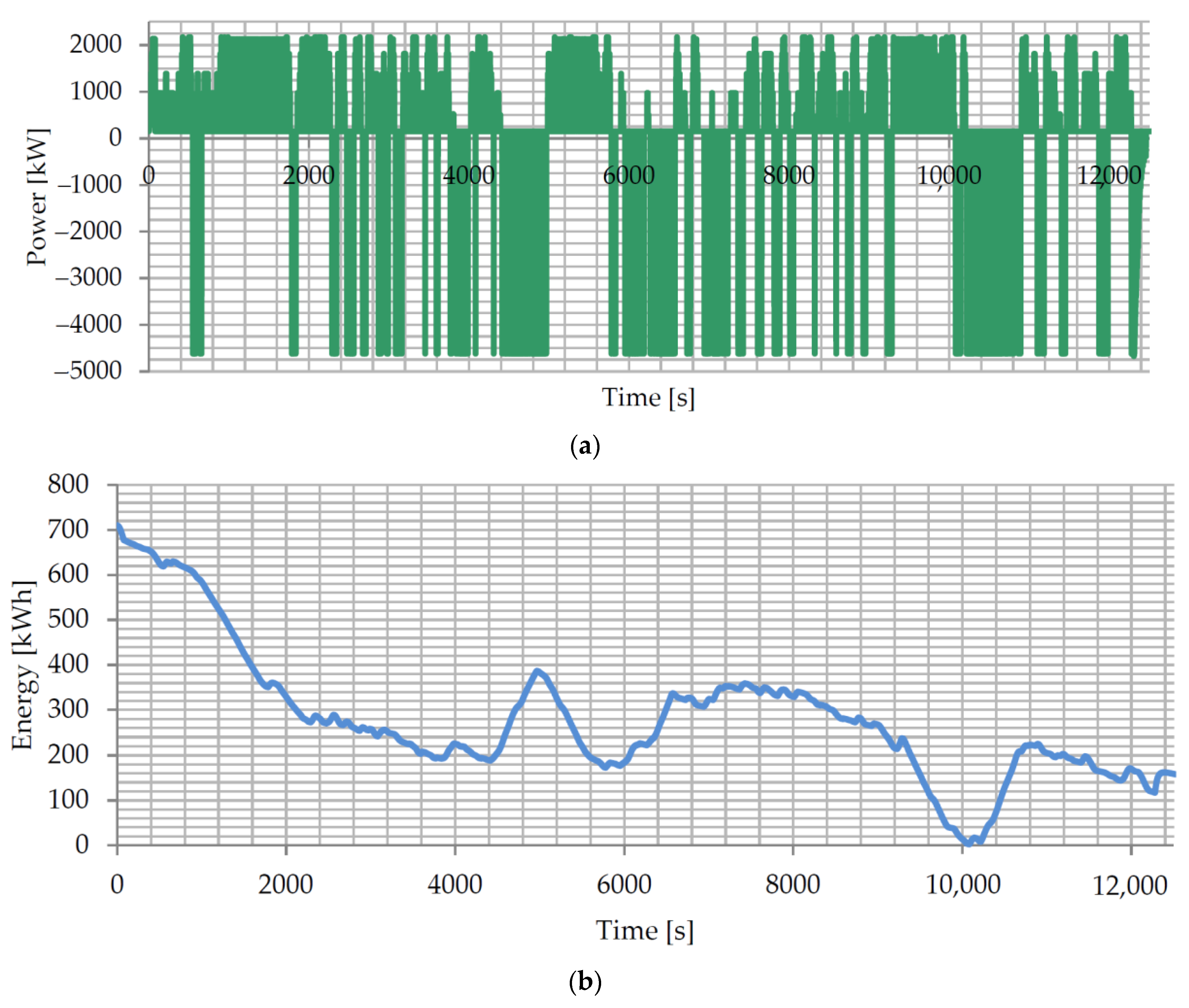
Figure 11.
Time dependences of power (a) and energy change (b) of the accumulator when moving from the Kharkiv-Sortuvanny station to the Sumy station with empty wagons.
The analysis of the dependencies in Figure 10 and Figure 11 shows that intensive energy consumption occurs when moving uphill, and accumulation occurs when moving downhill. The maximum power of the energy storage in the traction mode of the booster section is 2156 kW, and in the energy storage mode with electrodynamic braking, this value is 2337 kW. To ensure the operation of the storage device, it must have a certain energy charge before starting [56,57]. At the same time, there is an almost monotonous change in energy in the accumulator, which allows us to estimate its minimum working energy capacity equal to the initial energy before movement.
Thus, the use of energy storage on the booster section reduced fuel consumption during movement by half. As a result of the fact that accumulation is only carried out from the booster section, about half of the available energy is stored. The performance indicators of the diesel engine do not change.
3.3. Modeling the Movement of a Train with a Diesel Locomotive as Part of a Diesel Section and a Booster Section with an Energy Storage Unit with Combined Traction Systems (Option 3)
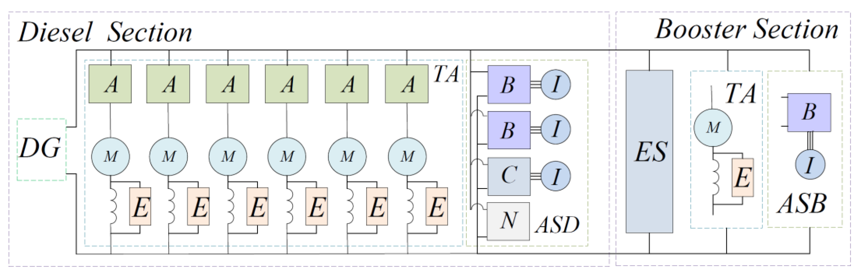
As can be seen from the analysis of the previous simulation results, energy accumulation from only one section does not exhaust the entire energy saving potential. Therefore, the case was considered when, in the mode of electrodynamic braking, energy accumulation can occur both from the booster section and from the diesel section. At the same time, the energy storage is located in the booster section. In this case, the traction system of the diesel section will have a structure similar to the structure of the booster section (Figure 12).
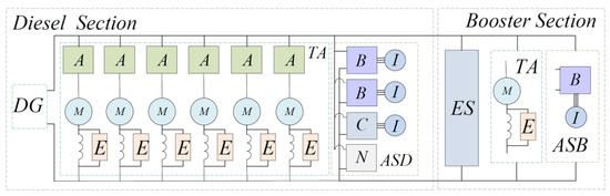
Figure 12.
Structural diagram of the traction system of the diesel section for the case of energy accumulation both from the booster section and from the diesel section during electrodynamic braking.
In Figure 12, the following designation is used: ASD—auxiliary system of the booster section. Other designations are shown in Figure 3 and Figure 7.
To provide energy return from the electric motors of the diesel section to the accumulator, which is located in the booster section, the power circuits of the diesel and booster sections are connected into a single link. At the same time, in the traction mode, only the traction electric motors of the booster section receive power from the energy storage.
The traction characteristics of the sections shown in Figure 8 and the limiting braking characteristics shown in Figure 9 were used in the simulation.
The calculation of energy exchange processes in the energy storage is carried out as follows.
The power that is exchanged between the storage unit and the traction electric drive is
where PkD—tangential power of the diesel section;
- PauxD—the power of auxiliary systems of the diesel section (taken to be equal to 200 kW);
- Pk—tangential power of the diesel locomotive.
The total efficiency of the traction electric drive, ηTD, is taken to be equal to 0.90 for the traction mode and the electrodynamic braking mode for both the booster and diesel sections.
Positive values of storage capacity correspond to discharging, with negative values to charging.
The change in energy in the accumulator is determined by the expression
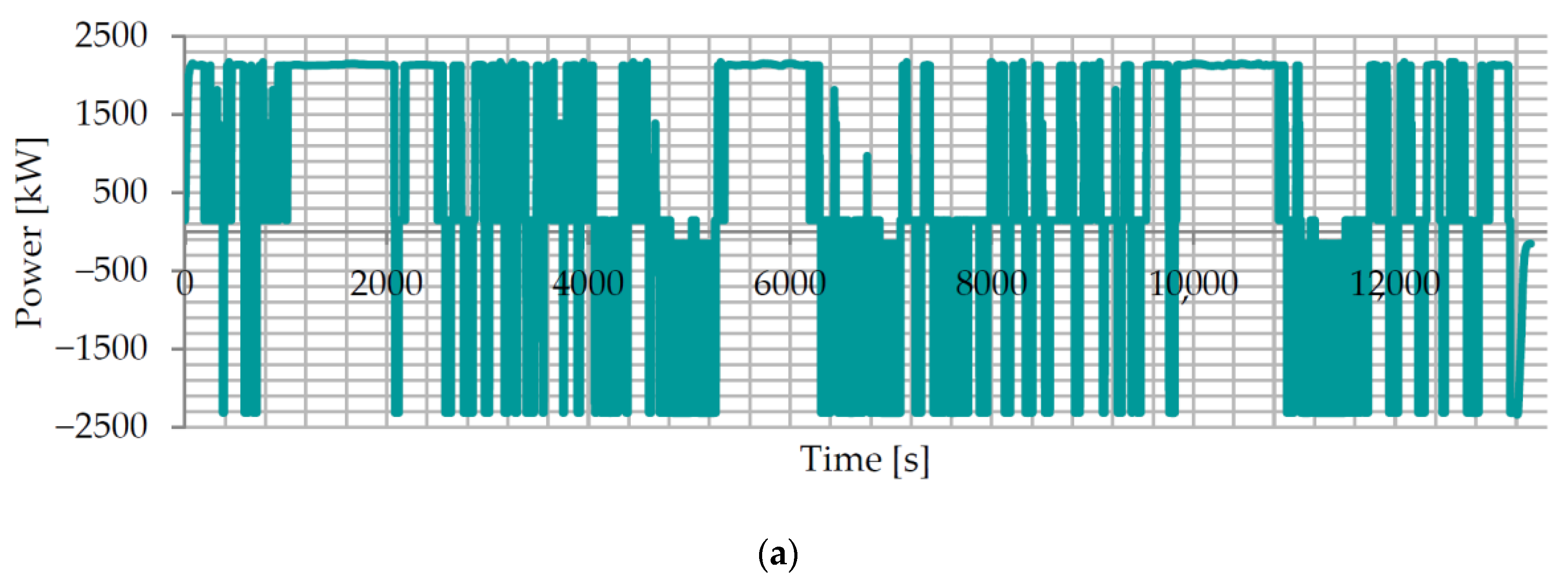
As in the previous cases, the simulation was performed for the movement of the train with loaded and empty wagons in both directions. The calculation results are given in Table 5. Figure 13 and Figure 14 show the time dependences of power and storage energy changes for the studied variant.
Table 5.
The change in energy in the accumulator is determined by the expression.

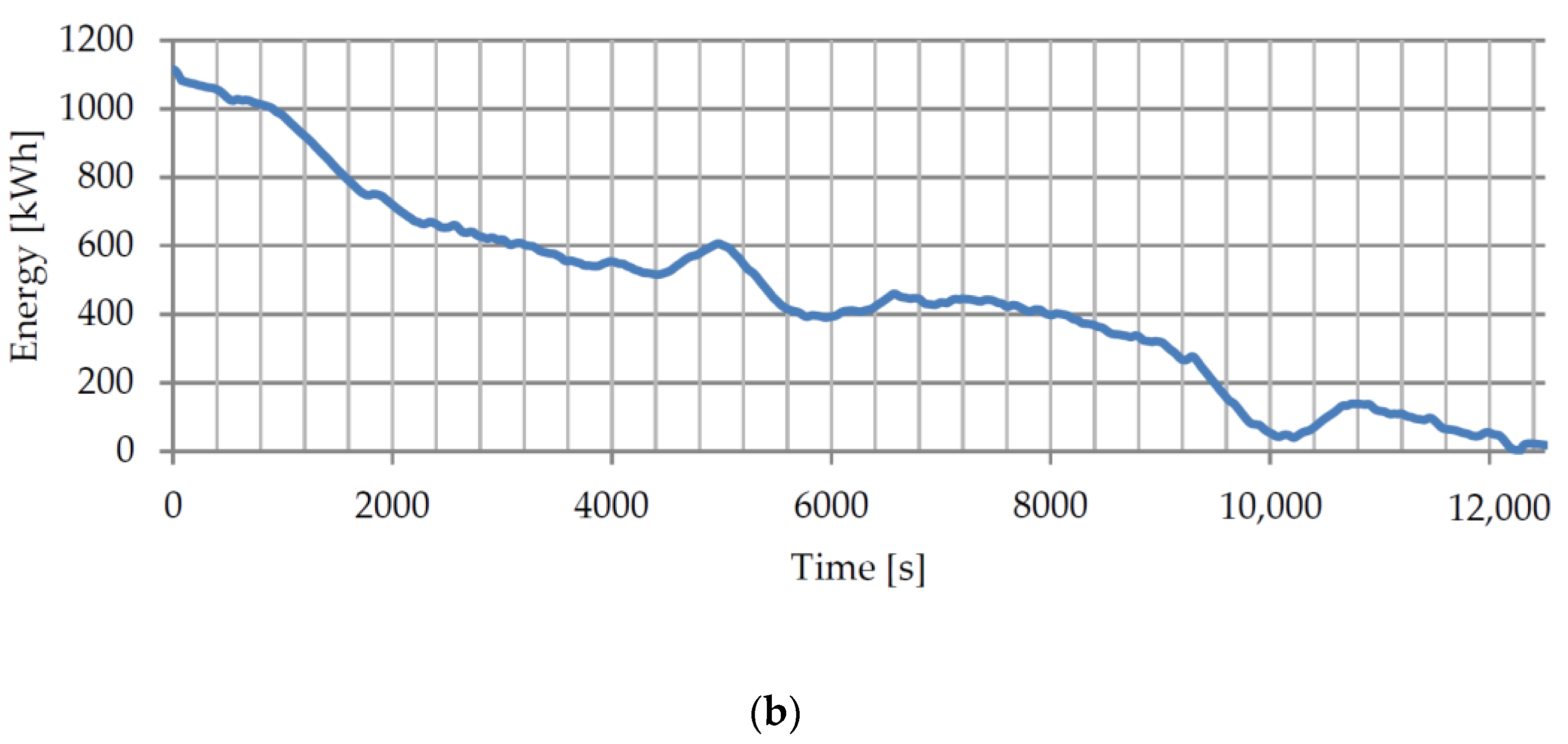
Figure 13.
Time dependences of power (a) and energy change (b) of the accumulator when moving from the Kharkiv-Sortuvalnyi station to the Sumy station with loaded wagons.
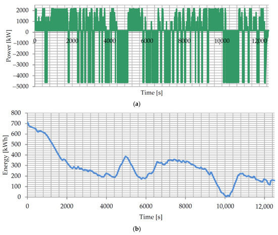
Figure 14.
Time dependences of power (a) and energy change (b) of the accumulator when moving from Kharkiv-Sortuvalnyi station to Sumy station with empty wagons.
The analysis of movement parameters according to the data in Table 5 shows that they correspond to the traffic parameters with a serial diesel locomotive.
Table 5 shows that the actual coefficients of energy accumulation are practically equal to the theoretical value (the excess of the actual coefficient over the theoretical one is explained by the approximate calculation of its value). This is explained by the fact that energy is accumulated both from the traction electric drive of the booster section and from the diesel section. Fuel consumption by the diesel section is reduced by about half.
From Figure 10 and Figure 11, it can be seen that intensive energy consumption occurs when moving uphill, and accumulation occurs when moving downhill. The maximum power of the energy storage in the traction mode of the booster section is 2156 kW, and in the energy storage mode with electrodynamic braking, this value is 4674 kW. To ensure the operation of the drive, it must have a certain charge of energy before starting. The analysis of the dependences of the energy change in the accumulator shows that it is characterized by a significant discharge of the energy accumulator as well as charging. At the same time, energy accumulates in the accumulator at the end of the movement. The minimum working energy capacity can be estimated at the level of the initial energy that must be in storage before starting the movement. It should be noted that the values of the working capacity of the drive for option 3 are significantly lower than those for the drive used according to option 2.
Thus, the use of an energy storage device to accumulate energy from the booster and diesel sections reduced fuel consumption during driving by half. At the same time, all energy that is available during electrodynamic braking is stored. The performance indicators of the diesel engine do not change.
4. Discussion of the Obtained Results
As a result of the conducted research, the effectiveness of the use of energy storage devices on the main freight diesel locomotive has been established. In order to determine a more effective organization of the traction system of a mainline diesel locomotive, a comparison of the obtained calculation results was made for the second (diesel section and booster section with energy storage) and the third (diesel section and booster section with energy storage with combined traction systems) options for organizing the traction drive of a mainline diesel locomotive.
As can be seen from Table 6, both cases of using the energy accumulator—for energy accumulation only from the booster section and accumulation from both the booster section and the diesel section—ensure a 50% reduction in fuel consumption compared to a serial diesel locomotive. The indicators that characterize the use of a diesel engine do not change. In both cases, when the train is moving with loaded wagons, the use of diesel engines based on the load can be considered effective. However, in terms of working time under load, diesel is only used for about half of the time. It is worth noting that these indicators are affected by the load algorithm of the diesel and booster sections, which, in this work, was assumed to be identical to the serial diesel locomotive. Therefore, in order to improve the use of diesel indicators, it is worth developing control algorithms that will ensure the improvement of diesel use, prioritizing the reduction in the duration of unproductive work.
Table 6.
The results of the comparison of the parameters of the train movement, obtained according to options 2 and 3.
The analysis of the indicators of the energy storage device shows that when storing energy only from the booster section, its power is approximately the same for both traction mode and storage mode. In the second case, the power in the storage mode is almost twice as high as the power in the energy return mode. At the same time, the working energy capacity for the second option is 1.57–2.25 less than for the first option.
For the normal functioning of the energy storage during movement, it must be initially charged. In the first case, using the storage device requires 2.25–1.57 times more energy, which must be stored in the storage device before the trip. That is, the total cost of fuel and energy resources for the trip will be higher in the first option of using the energy storage: before starting the movement, more energy must be accumulated in the storage. Charging can be carried out from a diesel section or—in case of long-term parking—from a specialized charging station [58,59].
When applying the energy storage according to the first variant of conversion, only one section of the diesel locomotive is subject to conversion. In the case of using the drive according to the second option, the conversion of both sections is necessary. In order to charge the energy storage, it is necessary to build appropriate infrastructure facilities [60,61,62]. In addition, the technological processes of stations, depots, and maintenance points should be optimized in order to ensure the charging of accumulators on the booster section and their diagnostics [63,64,65]. To increase the efficiency of the introduction of energy storage devices on the locomotive, it is necessary to develop energy-optimal management strategies for such locomotives [66,67,68].
Thus, with the investigated methods of using energy storage devices on the 2TE116 diesel locomotive, a two-fold reduction in fuel consumption during its movement on the route is achieved. At the same time, there is a need to charge the energy storage before starting movement, for which additional energy resources will be used. For the final choice of the energy storage option on the 2TE116 diesel locomotive, further research is required, taking into account the economic aspects of the diesel locomotive modernization and the creation of an infrastructure for servicing the energy storage.
5. Conclusions
Ways of improving the two-section mainline freight locomotive, in which energy storage is installed in one section instead of the diesel generator, are considered. The cases where the traction system of the section with energy storage is isolated from the traction system of the section with the diesel generator, as well as the case when the traction systems of both sections are connected, have been investigated. Through mathematical modeling, it was determined that in electrodynamic braking modes, depending on the configuration of the traction system, 32.64% of the energy spent in traction mode can be accumulated. The use of this energy in traction mode provides a reduction in fuel consumption when driving on the route by about 50%. To determine the final option of modernization, it is necessary to take into account the economic aspects that arise in connection with the introduction of an energy storage device during the modernization of a diesel locomotive.
Author Contributions
Conceptualization, I.R. and L.N.; methodology, S.G. and I.R.; software, S.G. and I.R.; validation, L.N. and I.R.; formal analysis, S.G. and I.R.; resources, I.R. and L.N.; data curation, I.R. and S.G.; writing—original draft preparation, I.R. and S.G.; writing—review and editing, L.N. and S.G.; visualization, I.R. and S.G.; supervision, I.R.; project administration, L.N. All authors have read and agreed to the published version of the manuscript.
Funding
This research received no external funding.
Data Availability Statement
Dataset available on request from the authors.
Conflicts of Interest
The authors declare no conflicts of interest.
References
- Available online: https://transport.ec.europa.eu/transport-themes/infrastructure-and-investment/trans-european-transport-network-ten-t_en (accessed on 1 February 2024).
- Kharchuk, O.; Kryvenko, O. Railway International Transport Corridors Ukraine and Role USCTS «Liski» in Their Development. Int. Sci. J. Internauka 2017, 15, 63–68. (In Ukrainian) [Google Scholar]
- Available online: https://www.uz.gov.ua/press_center/up_to_date_topic/607214/ (accessed on 1 February 2024).
- Smyrnov, I.; Lyubitseva, O.; Zapototskyi, S.; Hryniuk, D.; Stepanets, I. European Transport Corridors: Experience and Opportunities for Ukraine in Times of Danger. In Smart Technologies in Urban Engineering. STUE 2023; Lecture Notes in Networks and Systems, Arsenyeva, O., Romanova, T., Sukhonos, M., Biletskyi, I., Tsegelnyk, Y., Eds.; Springer: Cham, Switzerland, 2023; Volume 807. [Google Scholar] [CrossRef]
- Available online: https://www.wabteccorp.com/locomotive/heavy-haul-locomotives/es44aci-locomotive (accessed on 1 February 2024).
- Available online: https://logist.today/dnevnik_logista/2018-12-17/v-uz-rasskazali-kak-projavil-sebja-lokomotiv-trizub-v-pervyh-rejsah/ (accessed on 1 February 2024).
- Available online: https://finance.bigmir.net/news/2852901-made-in-ukraine-kakie-poezda-mogut-zamenit-staryj-park-ukrzaliznyci (accessed on 1 February 2024).
- Available online: https://trz.com.ua/modernization-ua/ (accessed on 1 February 2024).
- Kljaić, Z.; Pavković, D.; Cipek, M.; Trstenjak, M.; Mlinarić, T.J.; Nikšić, M. An Overview of Current Challenges and Emerging Technologies to Facilitate Increased Energy Efficiency, Safety, and Sustainability of Railway Transport. Future Internet 2023, 15, 347. [Google Scholar] [CrossRef]
- Cipek, M.; Pavković, D.; Kljaić, Z.; Trstenjak, M.; Mlinarić, T.J. Assessment of Battery-Hybrid Diesel-Electric Locomotive Fuel Savings and Emission Reduction Potentials Based on a Realistic Mountainous Rail Route. Energy 2019, 173, 1154–1171. [Google Scholar] [CrossRef]
- Mayrink, S., Jr.; Oliveira, J.G.; Dias, B.H.; Oliveira, L.W.; Ochoa, J.S.; Rosseti, G.S. Regenerative Braking for Energy Recovering in Diesel-Electric Freight Trains: A Technical and Economic Evaluation. Energies 2020, 13, 963. [Google Scholar] [CrossRef]
- Saeed, M.; Briz, F.; Guerrero, J.M.; Larrazabal, I.; Ortega, D. Onboard Energy Storage Systems for Railway: Present and Trends. Open J. Ind. Appl. 2023, 4, 238–259. [Google Scholar] [CrossRef]
- Li, W.; Wang, C.; Pei, H.; Xu, C.; Lin, G.; Deng, J.; Jiang, D.; Huang, Y. An Improved Energy Management Strategy of Diesel-Electric Hybrid Propulsion System Based on FNN-DP Strategy. Electronics 2023, 12, 486. [Google Scholar] [CrossRef]
- Meinert, M.; Prenleloup, P.; Schmid, S.; Palacin, R. Energy Storage Technologies and Hybrid Architectures for Specific Diesel-Driven Rail Duty Cycles: Design and System Integration Aspects. Appl. Energy 2015, 157, 619–629. [Google Scholar] [CrossRef]
- Available online: https://www.wabteccorp.com/locomotive/alternative-fuellocomotives/flxdrive (accessed on 1 February 2024).
- Sun, Y.; Cole, C.; Spiryagin, M.; Godber, T.; Hames, S.; Rasul, M. Conceptual Designs of Hybrid Locomotives for Application as Heavy Haul Trains on Typical Track Lines. Proc. Inst. Mech. Eng. Part F J. Rail Rapid Transit 2013, 227, 439–452. [Google Scholar] [CrossRef]
- da Silva Moraes, C.G.; Brockveld, S.L.; Heldwein, M.L.; Franca, A.S.; Vaccari, A.S.; Waltrich, G. Power Conversion Technologies for a Hybrid Energy Storage System in Diesel-Electric Locomotives. IEEE Trans. Ind. Electron. 2021, 68, 9081–9091. [Google Scholar] [CrossRef]
- Fedele, E.; Iannuzzi, D.; Pizzo, A.D. Onboard Energy Storage in Rail Transport: Review of Real Applications and Techno-Economic Assessments. IET Electr. Syst. Transp. 2021, 11, 279–309. [Google Scholar] [CrossRef]
- Omelyanenko, V.I.; Riabov, I.S.; Overianova, L.V.; Omelianenko, H.V. Traction Electric Drive Based on Fuel Cell Batteries and On-Board Inertial Energy Storage for Multi Unit Train. Electr. Eng. Electromechan. 2021, 4, 64–72. [Google Scholar] [CrossRef]
- Kapetanović, M.; Núñez, A.; van Oort, N.; Goverde, R.M.P. Reducing Fuel Consumption and Related Emissions Through Optimal Sizing of Energy Storage Systems for Diesel-Electric Trains. Appl. Energy 2021, 294, 117018. [Google Scholar] [CrossRef]
- Mayet, C.; Pouget, J.; Bouscayrol, A.; Lhomme, W. Influence of an Energy Storage System on the Energy Consumption of a Diesel-Electric Locomotive. IEEE Trans. Veh. Technol. 2014, 63, 1032–1040. [Google Scholar] [CrossRef]
- Shiraki, N.; Satou, H.; Arai, S. A Hybrid System for Diesel Railcar Series Ki-Ha E200. In Proceedings of the 2010 International Power Electronics Conference—ECCE ASIA, Sapporo, Japan, 21–24 June 2010; pp. 2853–2858. [Google Scholar] [CrossRef]
- Fayad, A.; Ibrahim, H.; Ilinca, A.; Sattarpanah Karganroudi, S.; Issa, M. Energy Recovering Using Regenerative Braking in Diesel–Electric Passenger Trains: Economical and Technical Analysis of Fuel Savings and GHG Emission Reductions. Energies 2022, 15, 37. [Google Scholar] [CrossRef]
- Barbosa, F.C. Battery Only Electric Traction for Freight Trains—A Technical and Operational Assessment. Proc. Inst. Mech. Eng. Part F J. Rail Rapid Transit 2023, 238, 322–337. [Google Scholar] [CrossRef]
- Cipek, M.; Pavković, D.; Krznar, M.; Kljaić, Z.; Trstenjak, M.; Mlinarić, T.J. Comparative Analysis of Conventional Diesel-Electric and Hypothetical Battery-Electric Heavy Haul Locomotive Operation in Terms of Fuel Savings and Emissions Reduction Potentials. Energy 2021, 232, 121097. [Google Scholar] [CrossRef]
- Iden, M.E. Battery Storage of Propulsion-Energy for Locomotives. In Proceedings of the 2014 Joint Rail Conference, Colorado Springs, CO, USA, 2–4 April 2014. [Google Scholar] [CrossRef]
- Masliev, V. Modern Designs and Dynamics of Railway Rolling Stock; NTU “KhPI”: Kharkiv, Ukraine, 2014. (In Ukrainian) [Google Scholar]
- Zayonchkovskiy, V.; Masliev, V.; Yakunin, D. The General Structure, Thermal Calculations of Power Plants and Issues of Manufacturing Technology for the Crew Part of Diesel Locomotives; NTU “KhPI”: Kharkiv, Ukraine, 2008. (In Ukrainian) [Google Scholar]
- Tartakovsky, E.; Agulov, A.; Falendish, A.; Basov, G. Theory and Design of Locomotives. Part 1. General Characteristics and Structure of Locomotives; NTU “KhPI”: Kharkiv, Ukraine, 2006. (In Ukrainian) [Google Scholar]
- Available online: https://suspilne.media/273737-ukraina-i-moldova-vidnovili-alternativnij-zaliznicnij-marsrut-miz-odesou-ta-dunajskimi-portami/ (accessed on 1 February 2024).
- Krushedolsky, A.; Grishina, E. Adjustment of Diesel Locomotive Characteristics of a Forced Diesel Engine of a Main Diesel Locomotive. Intern. Combust. Engines 2009, 1, 103–106. (In Ukrainian) [Google Scholar]
- Bondarenko, I.; Severino, A.; Olayode, I.O.; Campisi, T.; Neduzha, L. Dynamic Sustainable Processes Simulation to Study Transport Object Efficiency. Infrastructures 2022, 7, 124. [Google Scholar] [CrossRef]
- Bosso, N.; Gugliotta, A.; Zampieri, N. Design and Simulation of a Railway Vehicle for the Transport of People with Reduced Mobility. Shock. Vib. 2018, 2018, 9207639. [Google Scholar] [CrossRef]
- Kalivoda, J.; Neduzha, L. Running Dynamics of Rail Vehicles. Energies 2022, 15, 5843. [Google Scholar] [CrossRef]
- Ye, Z.; Chen, Z.; Zhou, Z.; Zhai, W. Dynamic Modelling of Locomotive with Direct Drive Traction System Considering Electromechanical Coupling Effect. Veh. Syst. Dyn. 2023, 63, 1–24. [Google Scholar] [CrossRef]
- Holub, H.; Dmytrychenko, M.; Kulbovskyi, I.; Sapronova, S. Modeling of Energy-Saving Technologies in Traction Rolling Stock Projects. In Proceedings of the 7th ASRES International Conference on Intelligent Technologies. ICIT 2022, Jakarta, Indonesia, 16–18 December 2022; Lecture Notes in Networks and Systems. Arya, K.V., Tripathi, V.K., Rodriguez, C., Yusuf, E., Eds.; Springer: Singapore, 2023; Volume 683. [Google Scholar] [CrossRef]
- Dižo, J.; Blatnický, M.; Steišūnas, S. Multibody Simulation of Rail Vehicle Running Considering Track Flexibility. In TRANSBALTICA XI: Transportation Science and Technology; TRANSBALTICA 2019. Lecture Notes in Intelligent Transportation and Infrastructure; Gopalakrishnan, K., Prentkovskis, O., Jackiva, I., Junevičius, R., Eds.; Springer: Cham, Switzerland, 2020. [Google Scholar] [CrossRef]
- Sablin, O.; Bosyi, D.; Kuznetsov, V.; Lewczuk, K.; Kebal, I.; Myamlin, S.S. Efficiency of Energy Storage Control in the Electric Transport Systems. Arch. Transp. 2022, 62, 105–122. [Google Scholar] [CrossRef]
- Yatsko, S.; Sytnik, B.; Vashchenko, Y.; Sidorenko, A.; Liubarskyi, B.; Veretennikov, I.; Glebova, M. Comprehensive Approach to Modeling Dynamic Processes in the System of Underground Rail Electric Traction. East.-Eur. J. Enterp. Technol. 2019, 1, 48–57. [Google Scholar] [CrossRef]
- Zou, Z.; Zheng, M.; Lu, Q. Modeling and Simulation of Traction Power Supply System for High-Speed Maglev Train. World Electr. Veh. J. 2022, 13, 82. [Google Scholar] [CrossRef]
- Bondarenko, I.; Lukoševičius, V.; Keršys, R.; Neduzha, L. Investigation of Dynamic Processes of Rolling Stock–Track Interaction: Experimental Realization. Sustainability 2023, 15, 5356. [Google Scholar] [CrossRef]
- Li, L.; Dutta, S.; Dixon, R.; Stewart, E. Railway Track Switch Simulation: A New Dynamic Model for Studying Actuator and Switch Blade Dynamics. Proc. Inst. Mech. Eng. Part F J. Rail Rapid Transit 2023, 237, 775–783. [Google Scholar] [CrossRef]
- Holub, H.; Kulbovskyi, I.; Skok, P.; Melnychenko, O.; Kharuta, V.; Bambura, O.; Tretynychenko, Y. System Model of Information Flows in Networks of the Electric Supply System in Transport Infrastructure Projects. In Proceedings of the Transport Means 2020: Proceedings of the 24th International Conference, Kaunas, Lithuania, 30 September–2 October 2020; pp. 132–135. [Google Scholar]
- Musayev, J.; Zhauyt, A.; Ismagulova, S.; Yussupova, S. Theory and Practice of Determining the Dynamic Performance of Traction Rolling Stock. Appl. Sci. 2023, 13, 12455. [Google Scholar] [CrossRef]
- Gołębiowski, P.; Góra, I.; Bolzhelarskyi, Y. Risk Assessment in Railway Rolling Stock Planning. Arch. Transp. 2023, 65, 137–154. [Google Scholar] [CrossRef]
- Kyrychenko, H.; Strelko, O.; Berdnychenko, Y.; Berdnychenko, I. Development of Automation of Operational Work of Railway Stations of Ukraine. In Proceedings of the 2023 IEEE International Conference on Information and Telecommunication Technologies and Radio Electronics (UkrMiCo), Kyiv, Ukraine, 13–18 November 2023; pp. 71–75. [Google Scholar] [CrossRef]
- Slashchev, V. Traction and Braking Calculations on Rail Transport; Eastern Ukrainian National University Named after V. Dalya: Luhansk, Ukraine, 2005. (In Ukrainian) [Google Scholar]
- Bobyr, D.; Grischenko, N.; Serdyuk, V.N. The Theory of Locomotive Traction; Educational and Scientific Institute “Dnipro Institute of Infrastructure and Transport”: Dnipro, Ukraine, 2022. (In Ukrainian) [Google Scholar]
- Riabov, I.; Goolak, S.; Kondratieva, L.; Overianova, L. Increasing the Energy Efficiency of the Multi-Motor Traction Electric Drive of an Electric Locomotive for Railway Quarry Transport. Eng. Sci. Technol. Int. J. 2023, 42, 101416. [Google Scholar] [CrossRef]
- Syrotenko, Y. Determining the Power of a Shunting Diesel Locomotive Taking into Account the Place of its Operation. East. -Eur. J. Enterp. Technol. 2014, 1, 41–45. Available online: http://nbuv.gov.ua/UJRN/Vejpte_2014_1(8)_9 (accessed on 1 February 2024). (In Ukrainian).
- Buriakovskiy, S.; Maslii, A.; Pomazan, D. Searching of The Optimum Configuration of The Traction Electric Transmission of The Shunting Locomotive. In Proceedings of the 2019 IEEE International Conference on Modern Electrical and Energy Systems (MEES), Kremenchuk, Ukraine, 23–25 September 2019; pp. 22–25. [Google Scholar] [CrossRef]
- Goolak, S.; Riabov, I.; Tkachenko, V.; Sapronova, S.; Rubanik, I. Model of Pulsating Current Traction Motor Taking into Consideration Magnetic Losses in Steel. Electr. Eng. Electromechan. 2021, 6, 11–17. [Google Scholar] [CrossRef]
- Afanasov, A.M.; Shapovalov, O.S.; Holik, S.N.; Arpul, S.V.; Bilukhin, D.S. Energy efficiency of heat tests for traction electric machines. IOP Conf. Ser. Mater. Sci. Eng. 2020, 985, 012026. [Google Scholar] [CrossRef]
- Bodnar, B.; Kapitsa, M.; Bobyr, D.; Kyslyi, D. Defining the limits of application and the values of integration variables for the equations of train movement. Nauk. Visnyk Natsionalnoho Hirnychoho Universytetu 2019, 6, 59–65. [Google Scholar] [CrossRef]
- Pugi, L. Synergic Design and Simulation of Battery-Operated Trains on Partially Electrified Lines: A Case Study regarding the Firenze Faenza Line. Energies 2024, 17, 24. [Google Scholar] [CrossRef]
- Buriakovskiy, S.; Maslii, A.; Pomazan, D.; Panchenko, V.; Overianova, L.; Omelianenko, H. Multi-criteria Quality Evaluation of Energy Storage Devices for Rolling Stock Using Harrington’s Desirability Function. In Proceedings of the IEEE 7th International Conference on Energy Smart Systems (ESS), Kyiv, Ukraine, 12–14 May 2020; pp. 158–163. [Google Scholar] [CrossRef]
- Kondratieva, L.; Bogdanovs, A.; Overianova, L.; Riabov, I.; Goolak, S. Determination of the working energy capacity of the on-board energy storage system of an electric locomotive for quarry railway transport during working with a limitation of consumed power. Arch. Transp. 2023, 65, 119–135. [Google Scholar] [CrossRef]
- Noga, M. Research on the Possibility of Using a Hybrid Electric Vehicle Powertrain in V2X Applications; SAE Technical Paper 2022-01-1134; SAE International: Warrendale, PA, USA, 2022. [Google Scholar] [CrossRef]
- Guov, V.; Jackson, D.; Obi, M.; Cao, Y. Sizing BESS and On-site Renewable for Battery-electric Freight Rail Charging Station. In Proceedings of the 2022 IEEE 13th International Symposium on Power Electronics for Distributed Generation Systems (PEDG), Kiel, Germany, 26–29 June 2022; pp. 1–6. [Google Scholar] [CrossRef]
- Leijon, J.; Boström, C. Charging Electric Vehicles Today and in the Future. World Electr. Veh. J. 2022, 13, 139. [Google Scholar] [CrossRef]
- Aredah, A.; Du, J.; Hegazi, M.; List, G.; Rakha, H.A. Comparative analysis of alternative powertrain technologies in freight trains: A numerical examination towards sustainable rail transport. Appl. Energy 2024, 356, 122411. [Google Scholar] [CrossRef]
- Ruvio, A.; Bayrak, O. A preliminary design of a hybrid train’s on-board batteries for a 25 kV–50 Hz high speed railway line. J. Energy Storage 2024, 84 Pt B, 110966. [Google Scholar] [CrossRef]
- Kulbovskyi, I.; Holub, H.; Kyiashko, V.; Skliarenko, I.; Sorochynska, O.; Gurenkova, O.; Kharuta, V. Investigation of the model of functioning of production and technological potential of subway power supply departments. In Proceedings of the Transport Means 2020: Proceedings of the 24th International Conference, Kaunas, Lithuania, 30 September–2 October 2020; pp. 416–420. [Google Scholar]
- Gubarevych, O.; Goolak, S.; Melkonova, I.; Yurchenko, M. Structural Diagram of the Built-in Diagnostic System for Electric Drives of Vehicles. Diagnostyka 2022, 23, 2022406. [Google Scholar] [CrossRef]
- Urbaniak, M.; Kardas-Cinal, E.; Jacyna, M. Optimization of Energetic Train Cooperation. Symmetry 2019, 11, 1175. [Google Scholar] [CrossRef]
- Cipek, M.; Pavković, D.; Kljaić, Z. Optimized Energy Management Control of a Hybrid Electric Locomotive. Machines 2023, 11, 589. [Google Scholar] [CrossRef]
- Buriakovskyi, S.; Asmolova, L.; Obruch, I.; Maslii, A.; Pomazan, D. Simulation Modeling of a Hybrid Diesel Locomotive Power Plant Based on a Free-Piston Engine. In Proceedings of the 2022 IEEE 4th International Conference on Modern Electrical and Energy System (MEES), Kremenchuk, Ukraine, 20–23 October 2022; pp. 1–4. [Google Scholar] [CrossRef]
- Afanasov, A.; Linik, D.; Arpul, S.; Belukhin, D.; Vasylyev, V. Prospects of Using Autonomous Electric Trains with Onboard Storage Stores. Transp. Syst. Transp. Technol. 2022, 23, 46–51. [Google Scholar] [CrossRef]

Disclaimer/Publisher’s Note: The statements, opinions and data contained in all publications are solely those of the individual author(s) and contributor(s) and not of MDPI and/or the editor(s). MDPI and/or the editor(s) disclaim responsibility for any injury to people or property resulting from any ideas, methods, instructions or products referred to in the content. |
© 2024 by the authors. Licensee MDPI, Basel, Switzerland. This article is an open access article distributed under the terms and conditions of the Creative Commons Attribution (CC BY) license (https://creativecommons.org/licenses/by/4.0/).