Article

Analysis and Preliminary Design of Variable Flux Reluctance Machines: A Perspective from Working Field Harmonics

1
Department of Industrial Engineering, University of Padova, 35131 Padova, Italy
2
College of Automation Engineering, Nanjing University of Aeronautics and Astronautics, Nanjing 210016, China
*
Author to whom correspondence should be addressed.
Vehicles 2024, 6(1), 571-589; https://doi.org/10.3390/vehicles6010026
Submission received: 2 February 2024 / Revised: 13 March 2024 / Accepted: 16 March 2024 / Published: 21 March 2024

Abstract

:
Variable flux reluctance machines (VFRMs) are increasingly attracting research interest due to their magnetless and robust brushless structure. Under the modulation effect of the airgap permeance, the VFRM operates with a series of field harmonics, distinguishing it from conventional AC synchronous machines. This paper deals with the analysis and preliminary design of the VFRM from the perspective of multiple working airgap field harmonics. Firstly, the spatial and temporal order of the working field harmonics are defined. The systematic winding theory, including the unified star of slots and winding factor calculation method, is established to consider all these working harmonics. Then, an average torque model is built and simplified. The key role of 1st-order rotor permeance, 1st- and 3rd-order polarized stator permeance is deduced. The relationship between key parameters and average torque is computed, providing a guideline for the preliminary design of the VFRM.

1. Introduction

Electric vehicles are gaining widespread interest today due to their economic advantages as well as climate and environmental awareness [1,2]. The electrical machine is a core component for electric vehicle propulsion, and therefore, the proper type selection of the electrical machines is very essential [3,4]. Benefiting from the outstanding magnetic properties of rare-earth permanent magnets (PMs), PM machines have been widely used in existing commercial electric vehicles or hybrid electric vehicles with the advantages of high power density and high efficiency [5,6]. However, due to the increasing concerns about the high costs and potential environmental problems associated with the extraction of rare earth PMs, less or no rare-earth machines are increasingly being considered and developed [7].
In a PM machine rotor, the PMs can be replaced by the DC field winding, achieving conventional rotor wound synchronous machines (RWSMs) [8,9]. They are mature technologies and have the advantages of reliable de-excitation ability and simple control methods. Nevertheless, brushes/slip rings or other brushless excitation structures are required to power the rotor wound field winding [10,11], reducing the reliability and maintainability. The switched reluctance machine (SRM) is another type of magnetless machine. It has a simple and robust iron rotor structure, attracting much attention in recent years [12,13]. However, the SRM suffers from high levels of torque ripple, vibrations, and acoustic noise due to the doubly salient structure and special unipolar nonsinusoidal excitation method [14], limiting its application in electric passenger vehicles.
The variable flux reluctance machine (VFRM) proposed in [15] can be derived from the SRM excited by sinusoidal bipolar excitation with DC bias [16]. It features the same doubly salient structure, but a new set of DC field windings is introduced and placed on the stator together with the armature windings. The VFRM inherits its advantages from the SRM, such as a brushless robust rotor structure, non-overlapping concentrated windings, and good thermal management. Apart from this, compared with the SRM, the VFRM can be driven by a standard controller with a bipolar sinusoidal current with the advantages of a lower torque ripple [17,18]. Due to these merits, the VFRM has been well explored for electric vehicle applications, and it is considered as a strong candidate as the main traction motor [19,20,21]. Also, due to the inherent magnetic gear principle, the VFRM is seen as a kind variant of the Vernier reluctance machine [22], in which a small displacement of the rotor produces a large permeance variation [23].
The operation principle and torque production mechanism of the VFRM have been analyzed and investigated widely. Using the same method as the SRM, the torque equation can be derived based on the inductance variation [24,25]. The instantaneous torque model was built but the relationship between the magnetic field and the electromagnetic torque was not established. From the perspective of a Vernier reluctance machine, the magnetic gearing principle can be used to explain the torque production of the VFRM [26]. It reveals that two magnetic fields with different pole numbers can generate effective torque after modulation. The VFRM can be seen as a combination of various magnetic gear pairs, and then, the torque model using the magnetic gearing principle can be derived and investigated [27,28].
Based on the above magnetic gearing theory, there are a series of airgap field harmonics with different spatial orders contributing to the average torque production of the VFRM, which is different from the traditional AC synchronous machine. Due to this feature, the classic AC winding theory aimed at conventional AC machines with unique fixed pole pairs cannot be directly used for the design, modeling, and optimization of the VFRMs. This was not well considered in current studies. In this paper, the working synchronous field excitation harmonics in the airgap of the VFRM are defined. The systematic winding theory, including the unified star of slots and winding factor calculation method, is established to consider all these working harmonics. Based on this, a linear average torque model is built, simplified, and investigated. The relationship between the key parameters and the average torque performance is computed. A guideline for the preliminary design of the VFRMs is provided, which helps to speed up the design procedure.

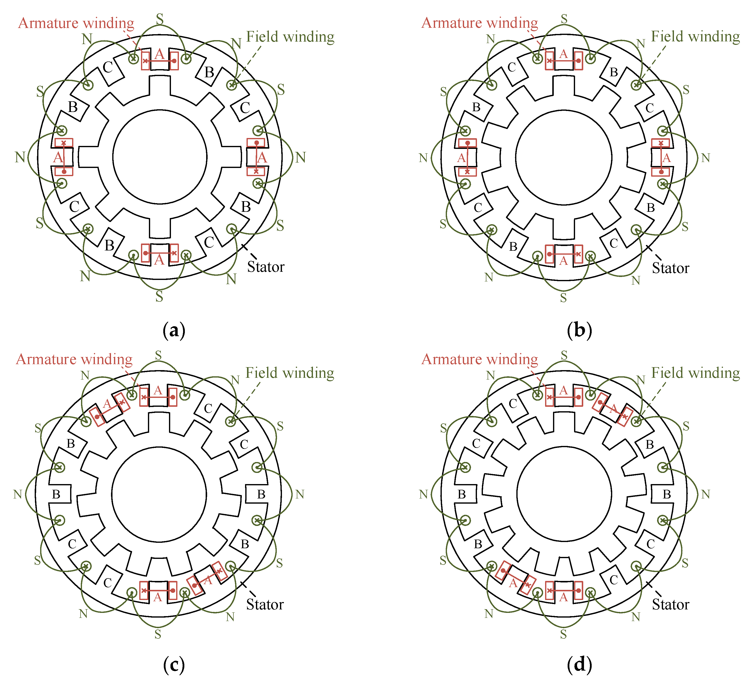
2. Structure and Operation Principle

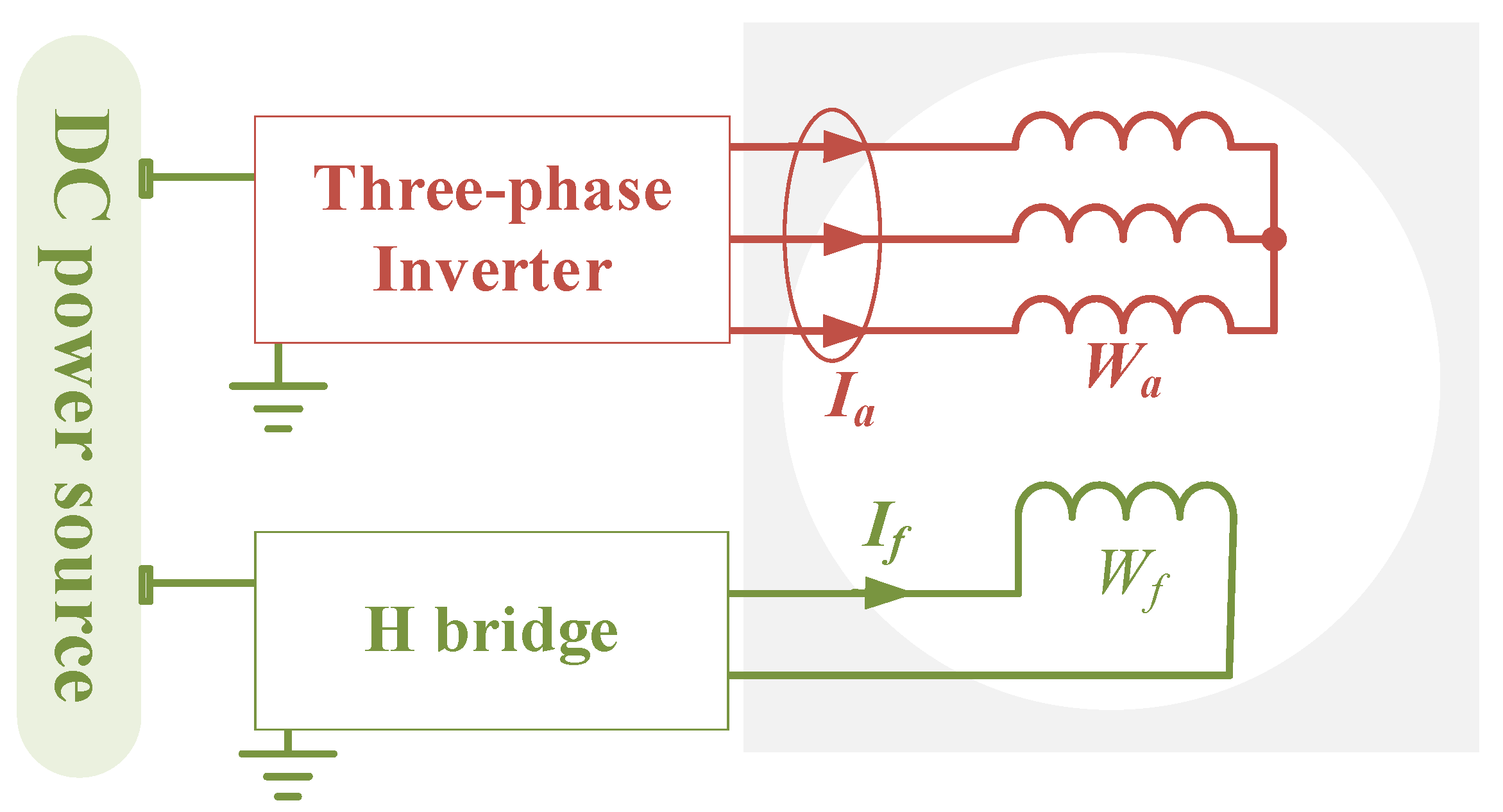
2.1. Topology and Drive System

Figure 1 shows the cross-section views of 12-stator-slot VFRMs with different rotor slots. The VFRM features a doubly salient structure. The salient iron rotor without any coils or magnets ensures reliable brushless operation. Both two sets of non-overlapped concentrated windings, namely the DC field winding and AC armature winding, are wound on any tooth of the stator. More specifically, the field winding is composed of 12 uniform coils with alternating polarities. The 3-phase armature windings are uniformly distributed, such as the A-phase armature winding in the figure.
Figure 2 shows the drive system of the VFRM. The armature winding (Wa) of the VFRM is fed by a standard 3-phase inverter with sinusoidal currents (Ia). The field current (If) of the field winding (Wf) is regulated by an H-bridge converter.

2.2. Operation Principle

Different from the conventional rotor-excitation synchronous machines (RESMs), the VFRM is a kind of stator-excitation synchronous machine. The DC excitation source is fixed, not rotating with the rotor. As shown in Figure 3, from the perspective of the armature coil A1 in the stator, the variation in the coupled flux linkage depends on the variation of the reluctance of the flux path, which is mainly decided by the relative position of the stator and rotor. At 0 mechanical degrees, the rotor tooth 1 aligns with the stator tooth A1, resulting in maximum flux linkage. With the rotation of the rotor, at 18 mechanical degrees, the rotor slot aligns with the stator tooth A1, and the flux linkage is at the minimum. Then, when the rotor tooth 2 aligns with the stator tooth A1, the flux linkage returns to the maximum value. This explains the variation in the flux linkage of the armature coil.
Also, it can be observed that an electrical period occurs every 36 mechanical degrees, when the flux linkage results in the same as that at 0 mechanical degrees. Therefore, the electrical period Te of the VFRM can be calculated as
T e = 2 π N r 1 Ω r
where Nr is the number of rotor slots, and Ωr is the mechanical angular speed of the rotor.
The electrical frequency fe is expressed as
f e = 1 T e = N r Ω r 2 π
Thus, the pole pair number of the VFRM is equal to its rotor slot number Nr. For example, a VFRM with 10 rotor slots has the same electrical frequency as an RESM with 20 rotor poles.
In this paper, this electrical frequency fe is defined as the fundamental electrical frequency, and the corresponding waveform is defined as the fundamental wave. The armature windings are fed by the 3-phase fundamental armature currents, written as
I A ( t ) = I a sin ( N r Ω r t ) I B ( t ) = I a sin ( N r Ω r t 2 3 π ) I C ( t ) = I a sin ( N r Ω r t + 2 3 π ) .

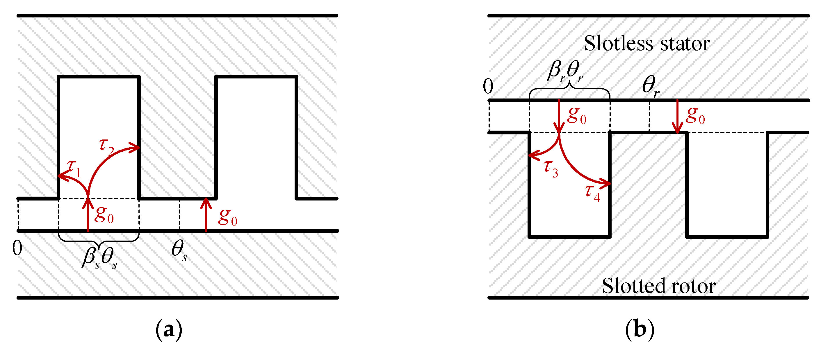
3. Analysis of No-Load Airgap Field Harmonics

Under the no-load condition, due to the modulation effect of the VFRM doubly slotted structure, there is an abundance of field harmonics in the airgap. Only harmonics with a specific temporal order can contribute to the average torque, which is defined as working harmonics. In this section, the temporal and spatial orders of these working field harmonics are clarified. The star of slots corresponding to all these working harmonics are unified. The winding factor calculation method is refined.

3.1. Definition of Working Field Harmonics

The no-load airgap flux density of a synchronous machine can be represented by
B g ( θ , t ) = B k cos ( P s p a t θ P t e m p Ω r t θ i n i t i a l )
where Bk is the magnitudes of kth-order flux density component, Pspat is the spatial order, Ptemp is the temporal order, and θinitial is the initial position.
The spatial order Pspat characterizes the pole pairs of the flux density harmonic, while the temporal order Ptemp characterizes the rotation speed. The flux linkage of a single stator coil A1 is given by the integral of the flux density over the airgap surface corresponding to the coil, as
ψ A 1 ( t ) = N a L R r τ s 2 τ s 2 B g ( θ , t ) d θ = 2 N a L R r B k sin ( P s p a t τ s / 2 ) P s p a c e cos ( P t e m p Ω r t + θ i n i t i a l )
where Na is the turn number of a stator coil, Rr is the rotor outer radius, L is the core length, and τs is the coil span angle. Equation (5) highlights that the value of the flux linkage depends on the rotor position.
After integration, the spatial order of the flux density only affects the amplitude of the flux linkage, while the temporal order will be retained to determine the electrical frequency on the stator winding side.
For the synchronous machine injected with standard sinusoidal armature currents, the average torque is only produced by the fundamental flux linkage. The corresponding flux density harmonics are defined as the working harmonics. This implies that the temporal order Ptemp of the working harmonics is fixed, while their spatial order Pspat is variable. For the VFRM, the working harmonics should satisfy
P t e m p = N r .

3.2. Spatial and Temporary Order of Working Harmonics
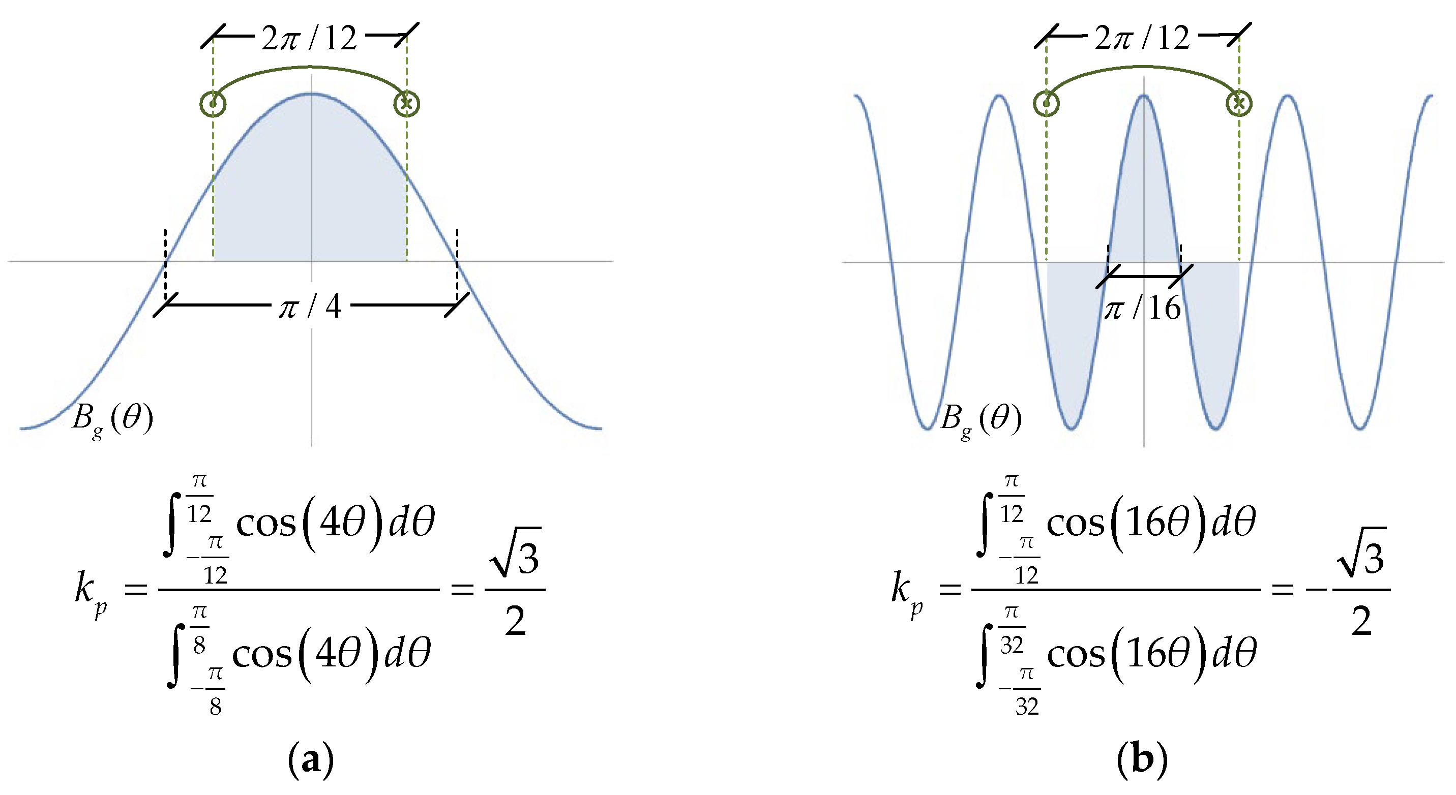
The no-load airgap flux density of the VFRM excited by the field current is given in (7). The detailed derivation can be found in Appendix A.
B g ( θ , t ) = 1 2 g 0 μ 0 N f I f n = 1 , 3 , 5 k = 0.1.2 Λ s f n Λ r k cos [ ( k N r ± n N s 2 ) θ k N r Ω r t ]
where μ0 is the vacuum permeability, g0 is the airgap length, Nf is the turn number of the field coil on one tooth, Λsfn is the amplitude of the nth-order component of the stator permeance polarized by the field winding, and Λrk is the amplitude of the kth-order component of the rotor permeance.
According to the definition of the working harmonics of the VFRM in (6), the temporal order of the working harmonics is
P t e m p = k 2 N r = N r .
Thus,
k 2 = 1 .
The spatial order is
P s p a t = N r ± n N s 2 .
The working flux density harmonics can be rewritten as
B g ( θ , t ) = 1 2 g 0 μ 0 N f I f Λ r 1 n = 1 , 3 , 5 Λ s f n cos [ ( N r ± n N s 2 ) θ N r Ω r t ] .
It can be observed that in the VFRM, there exists a series of working harmonics with different spatial orders, distinguishing it from traditional RESM.
For instance, Table 1 lists the spatial and temporal order of working harmonics in a 12-stator-slots/20-rotor-poles RESM and a 12-stator-slots/10-rotor-slots VFRM. The two machines exhibit the same electrical frequency. In the RESM, there is only one working harmonic. Both its temporal order and the spatial order are equal to 10, which is equal to the rotor pole pairs. On the contrary, in the VFRM, there are a series of working harmonics. The temporal orders are also 10, equal to the rotor slot number. The spatial orders are the combinations of the stator and rotor slot number, whose values are 4, 16, −8, 28… A negative spatial order indicates that the wave rotates in the opposite direction.

3.3. Winding Theory

In the traditional RESM, the electrical angle between the electromotive force (EMF) phasors of two adjacent slots is computed based on its stator slot number Ns and rotor pole pairs p, that is
α s e = 2 π p N s .
Building on the same concept, the slot electrical angle of the VFRM can be expressed as
α s e = 2 π P s p a t N s
The number of rotor pole pairs in (12) is replaced by the spatial order in (13) instead of the temporal order. This is because the phase difference of slot EMF phasors is determined by the number of pole pairs rather than the rotor speed.
By substituting (10) into (13), the electrical angle can be rewritten as
α s e = 2 π ( N r ± n N s 2 ) N s = 2 π N r N s ± n π
The different spatial orders of the working harmonics lead to different slot electrical angles. It is worth noting that the differences between these slot electrical angles are equal to a multiple of 2π. This means that a unified star of slots can be adopted for different working harmonics.
Comparing (13) and (14), it is evident that the RESM and the VFRM have different electrical angles despite them having the same electrical frequency and stator slot number. Specifically, the odd phasors are in-phase, and the even phasors are out-phase of 180 electrical degrees. Figure 4 shows the star of slots for the RESM and VFRM presented in the previous section. This paper considers double-layer windings.
Based on the analysis of the star of slots, the winding configuration can be determined. The winding factor of the working harmonics in the VFRM can be calculated. The same calculation method used in the fractional-slot PM machines [29] can be applied here to compute the distribution factor
k d = { sin ( q p h 2 α p h 2 ) q p h 2 sin ( α p h 2 )   when   N s 3 t   is   even sin ( q p h α p h 4 ) q p h sin ( α p h 4 )   when   N s 3 t   is   odd
where t is the greatest common divisor between the stator and rotor slot number, and
α p h = 2 π t N s q p h = N s 3 t .
The pitch factor relies on the coil throw. The slot pitch of the coil in the VFRM with concentrated windings is equal to 1. Thus, the coil span angle is equal to the slot electrical angle in (14). The pitch factor is given by
k p = sin ( α s e 2 ) = sin ( π P s p a t N s ) = sin ( π N r N s ± n π 2 ) = cos ( π N r N s ) sin ( ± n π 2 ) .
The value of kp is determined by the stator/rotor slots combination of the VFRM, but its sign is influenced by the spatial order of the working harmonic.
Figure 5 shows the pitch factor calculation of a 12s/10r VFRM at Pspat = 4 and Pspat = 10, respectively. The pitch factor is the ratio of the shaded area to a half-cycle sine wave area. In Figure 5a, the coil pitch is lower than the pole pitch, and kp is positive. On the contrary, in Figure 5b, the coil pitch is higher than 2 pole pitches, and kp is negative.
Finally, the winding factor of the VFRM results
k w = k d k p .

4. Preliminary Parameter Design

In this section, a linear torque model is established. Since the core saturation is not considered, this torque model cannot be used for accurate calculation. However, based on the analysis of the linear model, the guideline for the preliminary design of VFRMs can be summarized, which helps to accelerate the design process.

4.1. Torque Model

The average torque model (19) in the linear condition can be derived from the flux density model given in (11). The detailed procedure is illustrated in Appendix B.
T a v g = 2 R r L g 0 μ 0 N r ( N a I a ) ( N f I f ) Λ r 1 k d cos ( N r N s π ) n = 1 , 3 , 5 Λ s f n sin ( n 2 π ) n n 2 4 ( N r N s ) 2
Figure 6 compares the analytical and FEA calculated torque of the VFRMs with stator slots Ns = 12 and varying rotor slots Nr. Each FEA model has the same geometry parameters and winding configuration setting as the corresponding analytical torque model. The relative permeability of cores in these FEA models is set to infinity to simulate the linear case. The good agreement at different rotor slot numbers verifies the accuracy of the torque model. Therefore, the torque model can be used to guide the preliminary design of the VFRM.

4.2. Distribution Rule of the Armature and Field Magnetomotive Force

The average torque is proportional to the product of the armature winding magnetomotive force (MMF) NaIa and the field winding MMF NfIf. Under the constraint of constant copper loss Pcu, the maximum average torque can be achieved when
N f I f = N a I a / 2
and
( N a I a ) ( N f I f ) = 2 8 k c u ρ c u l c o i l S s l o t P c u N s
where kcu is the slot fill factor, lcoil is the length of the one-turn coil, ρcu is the electrical conductivity of copper, and Sslot is the area of one stator slot. This distribution rule applies to VFRMs with different stator/rotor slot combinations.

4.3. Approximate Torque Model and Stator/Rotor Slot Combination

According to the torque model (19), the average torque includes a series of torque components Tavgn, generated by the working harmonics with spatial orders of (Nr ± nNs/2). Then, the torque can be reformulated as
T a v g = n = 1 , 3 , 5 T a v g n
T a v g n = 2 4 R r L g 0 μ 0 k c u ρ c u l c o i l S s l o t P c u Λ r 1 k d N r N s cos ( N r N s π ) sin ( n 2 π ) n Λ s f n n 2 4 ( N r N s ) 2 .
Figure 7 plots the average torque component Tavgn of a 12s/10r VFRM. It can be found that the majority of the average torque is due to the low-order harmonics. Thus, the high-order harmonic components can be neglected to simplify the torque model used for the preliminary design.
The 1st- and 3rd-order terms are retained in the approximate torque model
T a v g = T a v g 1 + T a v g 3 .
Substituting (23), it can be rewritten as
T a v g = 2 4 R r L g 0 μ 0 k c u ρ c u l c o i l P c u S s l o t Λ r 1 k d N r N s cos ( N r N s π ) [ Λ s f 1 1 - 4 ( N r N s ) 2 3 Λ s f 3 9 - 4 ( N r N s ) 2 ] .
Then, the torque error between two torque models (19) and (25) is defined as
δ T = ( T a v g 1 + T a v g 3 ) T a v g T a v g .
The stator/rotor slot combination has a major influence on the torque output of the VFRM. Figure 8 shows the average torque Tavg calculated by the torque model (19) and the torque error δT caused by the approximate torque model (25).
Firstly, the VFRM always exhibits higher torque when the ratio Nr/Ns is close to 1 for various stator slot numbers ranging from 6 to 24. If Nr/Ns is outside the range from 0.5 to 1.5, the torque decreases significantly. Combinations of stator/rotor slots outside this range are filtered out and not considered in the subsequent analysis.
Moreover, within the constraint of Nr/Ns ranging from 0.5 to 1.5, the torque error is within ±5%. The error is most pronounced for low Ns and decreases significantly with increasing Ns. Therefore, the feasibility and accuracy of the approximate torque model can be guaranteed for the VFRMs with constrained stator/rotor slot combinations. Also, it can be concluded that the spatial order of the working harmonics that significantly contributes to the average torque is Nr ± Ns/2 and Nr ± 3Ns/2.

4.4. Rotor Geometric Design

The torque equation demonstrated that the rotor design of the VFRM can be optimized in terms of the 1st-order rotor permeance Λr1. The average torque is proportional to Λr1.
According to the rotor permeance equation provided in Appendix C, Λr1 is determined by the geometric parameters, including the airgap length g0, the rotor outer radius Rr, and the rotor slot opening to slot pitch ratio βr (abbreviated as the rotor slot opening ratio). For the rotor geometric design, the key geometric parameter to be optimized is the rotor slot opening ratio. The increase in the rotor outer radius leads to higher Λr1, but it is constrained by the stator slot area, which will discussed in the following section.
Figure 9 illustrates the 1st-order rotor permeance Λr1 by scanning the rotor slot opening ratio βr. The same curve can be observed at different rotor slot numbers Nr. The maximum Λr1 is achieved at an optimal rotor slot opening ratio of approximately 0.5 to 0.55. The increase in the airgap length leads to a slight increase in the optimal rotor slot opening ratio. This optimal value can be used in the preliminary rotor design of different VFRMs. Taking βr = 0.5 for instance, the rotor slot pitch angle of 12s/8r, 12s/10r, 12s/11r, and 12s/13r is 45, 36, 32.7, and 27.7 degrees, respectively, and thus, the corresponding rotor slot opening angle is 22.5, 18, 16.35, and 13.85 degrees.
Furthermore, Figure 10 shows the average torque of a 12s/10r VFRM versus the rotor slot opening ratio under linear condition. The analytical and FEA results verify the optimal rotor slot opening ratio.

4.5. Stator Geometric Design

Compared to the rotor design, the stator design is more complicated. Using the approximate torque model, the impact of the stator geometric parameters on the average torque is expressed by the 1st- and 3rd-order polarized stator permeance, Λsf1 and Λsf3, and the area of the stator slots Sslot. For the stator geometric design, the key geometric parameters to be optimized are the stator slot opening to slot pitch ratio βs (abbreviated as the stator slot opening ratio) and the stator inner radius Rs. Since the core saturation is not considered, the stator yoke thickness is kept at a constant value.
At constant stator outer radius R and stator yoke thickness hy, the stator inner radius is normalized and named the split ratio
d s = R s R h y .
Then, the stator slot area is computed
S s l o t = π N s ( R h y ) 2 [ ( 1 d s 2 ) 2 d s ( 1 d s ) ( 1 β s ) ] .
Due to the polarizing effect of the field winding, the polarized stator permeance exhibits different characteristics compared with the original permeance. Figure 11a shows the stator permeance distribution. Figure 11b shows the normalized field winding MMF distribution. The polarity is alternating positive and negative. Under the polarizing effect, the stator permeance in the positive pole remains unchanged, while the permeance in the negative pole reverses, as shown in Figure 11c. As a result, all even harmonics are canceled, as shown in Figure 11d. It means that Λsfn = 0 and Tavgn = 0 when n is even.
According to the stator permeance equation provided in Appendix C, Λsfn is mainly determined by the stator inner radius Rs and the stator slot opening ratio βs. Figure 12 illustrates Λsf1 and Λsf3 at different split ratio and stator slot opening ratio combinations. Λsf1 increases with the decrease in the stator slot opening ratio. In comparison, Λsf3 is relatively lower, and the curve has a local maximum point at about the stator slot opening ratio of 0.7. On the contrary, Λsf1 and Λsf3 are little affected by the changes in the split ratio.
Then, the influence of the stator slot opening ratio βs and split ratio ds on the average torque at constant copper loss can be expressed by Function F
F ( d s , β s ) = d s S s l o t Λ r 1 ( a 1 Λ s f 1 + a 3 Λ s f 3 )
with
a 1 = cos ( N r N s π ) 1 4 ( N r N s ) 2 a 3 = 3 cos ( N r N s π ) 9 + 4 ( N r N s ) 2 .
The two coefficients a1 and a3 are decided by the stator/rotor slots combination Nr/Ns. Figure 13 plots a1 and a3 versus Nr/Ns. As analyzed before, both Tavg1 and Tavg3 contribute significantly to the total torque. Thus, the average torque output can be guaranteed when both of the two components are positive. That means Nr/Ns should be restricted from 0.5 to 1.5, which is consistent with the finding in the earlier analysis.
Finally, Figure 14 shows the F value for different split ratio and stator slot opening ratio combinations with the constraint of constant copper loss. The optimal parameter combination of the VFRM can be determined by maximizing function F. In addition, it can be observed that the optimal parameter combination is influenced by Nr/Ns since the function F includes the variable Nr/Ns. Figure 15 collects the optimal split ratio and stator slot opening ratio of the VFRMs with various stator/rotor slot combinations. The trend is similar for the VFRMs with different stator slot numbers. There is a slight increase in both the optimal stator slot ratio and the optimal split ratio with increasing Nr/Ns. For the VFRMs with Nr/Ns near 1, the initial value of the stator split ratio and stator opening ratio can be set as 0.54 and 0.6, respectively. In the recommended range of Nr/Ns from 0.5 to 1.5, the same initial values can also be used, to unify and simplify the preliminary design process.

5. Conclusions

This paper deals with the analysis and preliminary design of the VFRM from the perspective of multiple working airgap field harmonics. The working harmonics feature the unique temporal order of Nr but different spatial order of Nr ± nNs/2 (n = 1, 3, 5…). It is found that a unified star of slots can consider all these working harmonics since the differences between their slot electrical angles are equal to a multiple of 2π. It is also deduced that the winding factors of these harmonics are the same, except for the sign, which is affected by the spatial order. Then, an average torque model of the VFRM is developed and simplified. This model takes into account the 1st-order rotor permeance and the 1st- and 3rd-order polarized stator permeance. Permeance harmonics of other orders are eliminated. By analyzing the torque model, the guideline for the preliminary design of the VFRM is obtained.

Author Contributions

Conceptualization, X.G. and N.B.; methodology, X.G., N.B. and Z.Z.; software, X.G.; formal analysis, X.G.; writing—original draft preparation, X.G.; writing—review and editing, N.B. and Z.Z.; supervision, N.B. and Z.Z.; project administration, N.B.; funding acquisition, N.B. All authors have read and agreed to the published version of the manuscript.

Funding

This research was funded by China Scholarship Council, grant number 202206830100.

Data Availability Statement

Data are contained within the article.

Acknowledgments

This study was carried out within the NEST—Network 4 Energy Sustainable Transition (D.D. 1243 02/08/2022, PE00000021), under the National Recovery and Resilience Plan (NRRP), Mission 4 Component 2 Investment 1.3—Call for tender No. 1561 of 11.10.2022 of Ministero dell’Università e della Ricerca (MUR), funded by the European Union—NextGenerationEU.

Conflicts of Interest

The authors declare no conflicts of interest.

Abbreviations

αseslot electrical angleμ0vacuum permeability
βrrotor slot opening to slot pitch ratioNaturn number of a stator coil
βsstator slot opening to slot pitch ratioNfturn number of a field coil
Bgno-load airgap flux densityNrrotor slot number
Bkmagnitudes of kth-order flux density Nsstator slot number
dssplit ratioPcucopper loss
δTtorque errorPspatspatial order
feelectrical frequencyPtemptemporal order
FfMMF of the field windingρcuelectrical conductivity of copper
fiith-order unit field winding MMFRstator outer radius
g0airgap lengthRsstator inner radius
hystator yoke thicknessRrrotor outer radius
Iffield currentSslotarea of one stator slot
Iaarmature current amplitudeτscoil span angle
kddistribution factorTavgaverage torque
kppitch factorTeelectrical period
kcuslot fill factorWaarmature winding
kwwinding factorWffield winding
Λradial airgap permeanceΩrmechanical angular speed
Λrradial airgap permeance of single-side salient-rotor modelΨaphase flux linkage amplitude
Λrkkth-order rotor permeanceθintialinitial position
Λsradial airgap permeance of single-
side salient-stator model
Lcore length
Λsfradial stator permeance polarized by the field windinglcoillength of the one-turn coil

Appendix A

The ideal radial no-load airgap flux density model for a doubly salient structure in linear condition is derived in [27,30], i.e.,
B r ( θ , t ) = F f ( θ ) Λ ( θ , t )
where Ff (θ) is the MMF of the field winding, and Λ(θ,t) is the airgap permeance.
The airgap permeance was given in [22], expressed as
Λ ( θ , t ) g 0 μ 0 Λ s ( θ ) Λ r ( θ , t )
where μ0 is the vacuum permeability, g0 is the airgap length, Λs(θ) is the radial airgap permeance of the single-side salient-stator model, and Λr(θ,t) is the airgap permeance of the single-side salient-rotor model.
Then, the airgap flux density model can be obtained by
B g ( θ , t ) = g 0 μ 0 F f ( θ ) Λ s ( θ ) Λ r ( θ , t ) = g 0 μ 0 N f I f Λ s f ( θ ) Λ r ( θ , t )
where Λsf (θ) is stator permeance polarized by the field winding (introduced in Appendix C), Nf is the turn number of the field winding on each stator tooth, and If is the field current.
The Fourier series expansion of Λr (θ,t) is written as
Λ r ( θ , t ) = k = 0 , 1 , 2 . . Λ r k cos [ k N r ( θ Ω r t ) ]
where Λrk is the amplitude of the kth-order component of rotor permeance, Nr is the rotor slot number, and Ωr is the mechanical angular speed of the rotor.
The Fourier series expansion of Λsf (θ) is written as
Λ s f ( θ ) = n = 1 , 3 , 5 . . Λ s f n cos ( n N s 2 θ )
where Λsfn is the amplitude of the nth-order component of the polarized stator permeance, and Ns is the stator slot number.
Substituting (30) and (A1) into (20), the flux density is
B g ( θ , t ) = g 0 μ 0 N f I f n = 1 , 3 , 5 . . Λ s f n cos ( n N s 2 θ ) k = 0 , 1 , 2 . . Λ r k cos [ k N r ( θ Ω r t ) ]   = 1 2 g 0 μ 0 N f I f n = 1 , 3 , 5 . . k = 0 , 1 , 2 . . Λ s f n Λ r k cos [ ( k N r ± n N s 2 ) θ k N r Ω r t ]

Appendix B

The flux linkage linked by a single armature coil on one stator tooth is computed as (A7). Only the working flux density harmonics with k = 1 in (A6) are considered.
ψ a ( t ) = N a R r L π / N s π / N s B g ( θ , t ) d θ   = N a R r L g 0 μ 0 ( N f I f ) Λ r 1 cos ( N r N s π ) n = 1 , 3 , 5 Λ s f n sin ( ± n 2 π ) N r ± n N s 2 cos ( N r Ω r t )   = Ψ a cos ( N r Ω r t )
where Na is the turn number of armature winding on each stator tooth, Rr is the rotor radius, and L is the core length. Finally, Ψa is the amplitude of the flux linkage.
The average torque can be deduced as
T a v g = 1 2 N s k d I a N r Ψ a   = 2 g 0 μ 0 R r L N r ( N f I f ) ( N a I a ) Λ r 1 k d cos ( N r N s π ) n = 1 , 3 , 5 Λ s f n sin ( n 2 π ) n n 2 4 ( N r N s ) 2
where kd is the distribution factor of the VFRM, and Ia is the amplitude of the sinusoidal armature current.

Appendix C

The calculation of the two permeance Λs (θ) and Λr (θ,t) can be carried out assuming an infinitely deep slot model, given in [30]. Figure A1 shows the equivalent airgap length in the infinitely deep slot model. The equivalent airgap length at the slot-facing position is the sum of the airgap length g0 and the parallel length of two quarter circles.
Figure A1. Equivalent airgap length in the infinitely deep slot model. (a) Single-slide salient-stator model; (b) single-slide salient-rotor model.
Vehicles 06 00026 g0a1
Λs (θ) and Λr (θ,t) are expressed as
Λ s ( θ ) = μ 0 g 0 + g s ( θ )
with
g s ( θ ) = { τ 1 τ 2 τ 1 + τ 2 = π R s 2 sin ( θ 2 ) sin ( β s θ s θ 2 ) sin ( β s θ s 4 ) cos ( θ 2 β s θ s 4 ) θ [ ( 1 β s ) θ s 2 , ( 1 + β s ) θ s 2 ] 0 θ [ 0 , ( 1 β s ) θ s 2 ] [ ( 1 + β s ) θ s 2 , θ s ]
θ s = 2 π N s
and
Λ r ( θ , t ) = μ 0 g 0 + g r ( θ Ω r t )
with
g r ( θ ) = { τ 3 τ 4 τ 3 + τ 4 = π R r 2 sin ( θ 2 ) sin ( β r θ r θ 2 ) sin ( β r θ r 4 ) cos ( θ 2 β r θ r 4 ) θ [ ( 1 β r ) θ r 2 , ( 1 + β r ) θ r 2 ] 0 θ [ 0 , ( 1 β r ) θ r 2 ] [ ( 1 + β r ) θ r 2 , θ r ]
θ r = 2 π N r
where βr is the rotor slot opening to slot pitch ratio, βs is the stator slot opening to slot pitch ratio, Rr is the rotor outer radius, and Rs is the stator inner radius.
Then, the Fourier series expansion of Λs(θ) and Λr(θ,t) can be given as (A4) and (A15).
Λ s ( θ ) = k = 0 , 1 , 2 . . Λ s k cos ( k N s θ )
The stator MMF of field winding and its Fourier series expansion are
  F f ( θ ) = { N f I f θ [ θ s 2 , θ s 2 ] N f I f θ [ θ s , θ s 2 ] [ θ s 2 , θ s ]
F f ( θ ) = N f I f i = 1 , 3 , 5 f i cos ( i N s 2 θ )
where fi is the amplitude of the ith-order component of the unit field winding MMF.
Thus, the stator permeance polarized by the field winding can be deduced as
Λ s f ( θ ) = F f ( θ ) N f I f Λ s ( θ ) = i = 1 , 3 , 5 . . f i cos ( i N s 2 θ ) k = 0 , 1 , 2 . . Λ s k cos ( k N s θ )   = i = 1 , 3 , 5 . . k = 0 , 1 , 2 . . 1 2 f i Λ s k cos [ ( i ± 2 k ) N s 2 θ ]   = n = 1 , 3 , 5 . . Λ s f n cos ( n N s 2 θ )

References

  1. Sanguesa, J.A.; Torres-Sanz, V.; Garrido, P.; Martinez, F.J.; Marquez-Barja, J.M. A Review on Electric Vehicles: Technologies and Challenges. Smart Cities 2021, 4, 372–404. [Google Scholar] [CrossRef]
  2. Malan, J.; Kamper, M.J. Performance of a Hybrid Electric Vehicle Using Reluctance Synchronous Machine Technology. IEEE IEEE Trans. Ind. Appl. 2001, 37, 1319–1324. [Google Scholar] [CrossRef]
  3. Zhu, Z.Q.; Howe, D. Electrical Machines and Drives for Electric, Hybrid, and Fuel Cell Vehicles. Proc. IEEE 2007, 95, 746–765. [Google Scholar] [CrossRef]
  4. Chau, K.T. Overview of Electric Vehicle Machines—From Tesla to Tesla, and beyond. In Proceedings of the 2016 International Conference of Asian Union of Magnetics Societies (ICAUMS), Tainan, China, 1–5 August 2016; pp. 1–6. [Google Scholar]
  5. Chau, K.T.; Chan, C.C.; Liu, C. Overview of Permanent-Magnet Brushless Drives for Electric and Hybrid Electric Vehicles. IEEE Trans. Ind. Electron. 2008, 55, 2246–2257. [Google Scholar] [CrossRef]
  6. EL-Refaie, A.M. Fractional-Slot Concentrated-Windings Synchronous Permanent Magnet Machines: Opportunities and Challenges. IEEE Trans. Ind. Electron. 2010, 57, 107–121. [Google Scholar] [CrossRef]
  7. Boldea, I.; Tutelea, L.N.; Parsa, L.; Dorrell, D. Automotive Electric Propulsion Systems with Reduced or No Permanent Magnets: An Overview. IEEE Trans. Ind. Electron. 2014, 61, 5696–5711. [Google Scholar] [CrossRef]
  8. Wang, Y.; Nuzzo, S.; Zhang, H.; Zhao, W.; Gerada, C.; Galea, M. Challenges and Opportunities for Wound Field Synchronous Generators in Future More Electric Aircraft. IEEE Trans. Transp. Electrif. 2020, 6, 1466–1477. [Google Scholar] [CrossRef]
  9. Chu, W.Q.; Zhu, Z.Q.; Zhang, J.; Liu, X.; Stone, D.A.; Foster, M.P. Investigation on Operational Envelops and Efficiency Maps of Electrically Excited Machines for Electrical Vehicle Applications. IEEE Trans. Magn. 2015, 51, 8103510. [Google Scholar] [CrossRef]
  10. Ayub, M.; Hussain, A.; Jawad, G.; Kwon, B.-I. Brushless Operation of a Wound-Field Synchronous Machine Using a Novel Winding Scheme. IEEE Trans. Magn. 2019, 55, 8201104. [Google Scholar] [CrossRef]
  11. Jawad, G.; Ali, Q.; Lipo, T.A.; Kwon, B.-I. Novel Brushless Wound Rotor Synchronous Machine with Zero-Sequence Third-Harmonic Field Excitation. IEEE Trans. Magn. 2016, 52, 8106104. [Google Scholar] [CrossRef]
  12. Bostanci, E.; Moallem, M.; Parsapour, A.; Fahimi, B. Opportunities and Challenges of Switched Reluctance Motor Drives for Electric Propulsion: A Comparative Study. IEEE Trans. Transp. Electrif. 2017, 3, 58–75. [Google Scholar] [CrossRef]
  13. Rahman, K.M.; Fahimi, B.; Suresh, G.; Rajarathnam, A.V.; Ehsani, M. Advantages of Switched Reluctance Motor Applications to EV and HEV: Design and Control Issues. IEEE Trans. Ind. Appl. 2000, 36, 111–121. [Google Scholar] [CrossRef]
  14. Lee, J.W.; Kim, H.S.; Kwon, B.I.; Kim, B.T. New Rotor Shape Design for Minimum Torque Ripple of SRM Using FEM. IEEE Trans. Magn. 2004, 40, 754–757. [Google Scholar] [CrossRef]
  15. Fukami, T.; Matsuura, Y.; Shima, K.; Momiyama, M.; Kawamura, M. Development of a Low-Speed Multi-Pole Synchronous Machine with a Field Winding on the Stator Side. In Proceedings of the XIX International Conference on Electrical Machines—ICEM 2010 (IEEE), Rome, Italy, 6–8 September 2010; pp. 1–6. [Google Scholar]
  16. Liu, X.; Zhu, Z.Q.; Pan, Z.P. Analysis of Electromagnetic Torque in Sinusoidal Excited Switched Reluctance Machines Having DC Bias in Excitation. In Proceedings of the 2012 XXth International Conference on Electrical Machines (IEEE), Marseille, France, 2–5 September 2012; pp. 2882–2888. [Google Scholar]
  17. Liu, X.; Zhu, Z.Q.; Hasegawa, M.; Pride, A.; Deodhar, R. Vibration and Noise in Novel Variable Flux Reluctance Machine with DC-Field Coil in Stator. In Proceedings of the Proceedings of 7th International Power Electronics and Motion Control Conference, Harbin, China, 2–5 June 2012; Volume 2, pp. 1100–1107. [Google Scholar]
  18. Raminosoa, T.; Torrey, D.A.; El-Refaie, A.M.; Grace, K.; Pan, D.; Grubic, S.; Bodla, K.; Huh, K.-K. Sinusoidal Reluctance Machine with DC Winding: An Attractive Non-Permanent-Magnet Option. IEEE Trans. Ind. Appl. 2016, 52, 2129–2137. [Google Scholar] [CrossRef]
  19. Zuurbier, M.M.J.; Fahdzyana, C.A.; Hofman, T.; Bao, J.; Lomonova, E.A. Geometric Optimization of Variable Flux Reluctance Machines for Full Electric Vehicles. In Proceedings of the 2019 Fourteenth International Conference on Ecological Vehicles and Renewable Energies (EVER), Monte-Carlo, Monaco, 8–10 May 2019; pp. 1–9. [Google Scholar]
  20. Liu, X.; Zhu, Z.Q.; Wu, D. Evaluation of Efficiency Optimized Variable Flux Reluctance Machine for EVs/HEVs by Comparing with Interior PM Machine. In Proceedings of the 2014 17th International Conference on Electrical Machines and Systems (ICEMS) (IEEE), Hangzhou, China, 22–25 October 2014; pp. 2648–2654. [Google Scholar]
  21. Zhao, X.; Niu, S.; Zhang, X.; Fu, W. Flux-Modulated Relieving-DC-Saturation Hybrid Reluctance Machine with Synthetic Slot-PM Excitation for Electric Vehicle In-Wheel Propulsion. IEEE Trans. Ind. Electron. 2021, 68, 6075–6086. [Google Scholar] [CrossRef]
  22. Jia, S.; Qu, R.; Li, J.; Li, D. Principles of Stator DC Winding Excited Vernier Reluctance Machines. IEEE Trans. Energy Convers. 2016, 31, 935–946. [Google Scholar] [CrossRef]
  23. Lee, C. Vernier Motor and Its Design. IEEE Trans. Power Appar. Syst. 1963, 82, 343–349. [Google Scholar] [CrossRef]
  24. Lee, B.; Zhu, Z.Q.; Huang, L. Investigation of Torque Production and Torque Ripple Reduction for Six-Stator/Seven-Rotor-Pole Variable Flux Reluctance Machines. IEEE Trans. Ind. Appl. 2019, 55, 2510–2518. [Google Scholar] [CrossRef]
  25. Zhou, X.; Zhou, B.; Wei, J. A Novel Position-Sensorless Startup Method for DSEM. IEEE Trans. Ind. Appl. 2018, 54, 6101–6109. [Google Scholar] [CrossRef]
  26. Jia, S.; Qu, R.; Kong, W.; Li, D.; Li, J. Flux Modulation Principles of DC-Biased Sinusoidal Current Vernier Reluctance Machines. IEEE Trans. Ind. Appl. 2018, 54, 3187–3196. [Google Scholar] [CrossRef]
  27. Huang, L.R.; Feng, J.H.; Guo, S.Y.; Shi, J.X.; Chu, W.Q.; Zhu, Z.Q. Analysis of Torque Production in Variable Flux Reluctance Machines. IEEE Trans. Energy Convers. 2017, 32, 1297–1308. [Google Scholar] [CrossRef]
  28. Huang, L.; Zhu, Z.Q.; Feng, J.; Guo, S.; Shi, J.X.; Chu, W. Analysis of Stator/Rotor Pole Combinations in Variable Flux Reluctance Machines Using Magnetic Gearing Effect. IEEE Trans. Ind. Appl. 2019, 55, 1495–1504. [Google Scholar] [CrossRef]
  29. Bianchi, N.; Dai Pre, M. Use of the Star of Slots in Designing Fractional-Slot Single-Layer Synchronous Motors. IEE Proc. Electr. Power Appl. 2006, 153, 459. [Google Scholar] [CrossRef]
  30. Gaussens, B.; Hoang, E.; de la Barriere, O.; Saint-Michel, J.; Lecrivain, M.; Gabsi, M. Analytical Approach for Air-Gap Modeling of Field-Excited Flux-Switching Machine: No-Load Operation. IEEE Trans. Magn. 2012, 48, 2505–2517. [Google Scholar] [CrossRef]
Figure 1. Cross-section view of 12-stator-slots VFRMs with only A-phase armature coils. (a) Eight rotor slots. (b) Ten rotor slots. (c) Eleven rotor slots. (d) Thirteen rotor slots.
Vehicles 06 00026 g001
Figure 2. Drive system of the VFRM.
Vehicles 06 00026 g002
Figure 3. Flux linkage waveform of armature coil A1 of a 12s/10r VFRM.
Vehicles 06 00026 g003
Figure 4. Star of slots; (a) 12-stator-slots/20-rotor-poles RESM, α s e = 300 ° ; (b) 12-stator-slots/10-rotor-slots VFRM, α s e = 120 ° ± n - 1 π .
Vehicles 06 00026 g004
Figure 5. Pitch factors of working harmonics in a 12s/10r VFRM. (a) Pspat = 4; (b) Pspat = 16.
Vehicles 06 00026 g005
Figure 6. Analytical and FEA calculated average torque in linear condition, with Ns = 12 and varying Nr.
Vehicles 06 00026 g006
Figure 7. Average torque component Tavgn of a 12s/10r VFRM.
Vehicles 06 00026 g007
Figure 8. Average torque and error of approximate torque model. (a) Ns = 6; (b) Ns = 12; (c) Ns = 18; (d) Ns = 24.
Vehicles 06 00026 g008
Figure 9. First-order rotor permeance. (a) g0 = 0.3 mm; (b) g0 = 1 mm.
Vehicles 06 00026 g009
Figure 10. Analytical and FEA calculated average torque versus rotor slot opening ratio.
Vehicles 06 00026 g010
Figure 11. Stator permeance. (a) Distribution of the stator permeance; (b) distribution of normalized field winding MMF; (c) distribution of the polarized stator permeance; (d) spectra of the polarized stator permeance.
Vehicles 06 00026 g011
Figure 12. First- and third-order polarized stator permeance.
Vehicles 06 00026 g012
Figure 13. Coefficients a1 and a3 versus Nr/Ns.
Vehicles 06 00026 g013
Figure 14. F values; (a) 12s/8r; (b) 12s/10r; (c) 12s/11r; (d) 12s/13r.
Vehicles 06 00026 g014
Figure 15. Optimal stator slot opening ratio and split ratio versus Nr/Ns. (a) Stator slot opening ratio; (b) split ratio.
Vehicles 06 00026 g015
Table 1. Spatial and temporary order of working flux density harmonics.
RESMVFRM
Stator slot number1212
Rotor pole number2010
Electrical frequency 10 Ω r 2 π 10 Ω r 2 π
Temporal order1010
Spatial order1010 ± 6n (n = 1, 3, 5…)
Disclaimer/Publisher’s Note: The statements, opinions and data contained in all publications are solely those of the individual author(s) and contributor(s) and not of MDPI and/or the editor(s). MDPI and/or the editor(s) disclaim responsibility for any injury to people or property resulting from any ideas, methods, instructions or products referred to in the content.

