Abstract
As automated driving has not yet been established, on narrow roads where there is no separation between pedestrians and vehicles, it is essential to switch to manual driving. However, when the driver turns the steering wheel from one hand to another on narrow roads, it causes steering burdens and operational errors if the steering feel or burden is not proper. Thus, this study aims to construct an active steering wheel system that provides an appropriate steering feel or burden by controlling the steering reaction torque, driving position and steering gear ratio for each driver. In this paper, we focused on and examined the driving position among these. A two-dimensional steering model that considers the size of the arms for each driver was established to evaluate steering burden. In addition, a basic study was conducted on the appropriate driving position. Then, based on the joint movements and angles calculation, the appropriate driving position that considers the size of the arms was studied by evaluating the joint power. As a result, it was found that if the steering wheel position is too close to the driver, the amount of joint movement increases, and if it is too far away, the joint movement decreases. Therefore, it was found that the appropriate steering wheel position for each driver’s arm length can be considered by using the joint power.
1. Introduction
Recently, small electric vehicles for one or two passengers, called “ultra-compact electric mobility vehicles”, have attracted attention in Japan. These vehicles are used for sharing and delivering services. Because they have a small turning circle, these vehicles are mainly used on narrow roads, in which there is no separation between pedestrians and vehicles. At low speeds on narrow roads, when the driver switches the steering wheel from one hand to another, it causes extensive shoulder burden and a sense of loss of turning direction, making it difficult for inexperienced drivers to control the vehicle [1]. Therefore, a system that controls the steering gear ratio, which is the ratio of the steering wheel operating angle to the steering angle of the tires, is required. This system reduces the steering gear ratio at low speeds, such as when turning at intersections and parking, to eliminate the need to switch the steering wheel from one hand to another. In addition, ultra compact electric mobility vehicles used for sharing are regardless of all ages and genders. Women and the elderly, whose upper limb muscle mass is inferior, may cause an accident [2,3]. Therefore, a steering system that does not impose a burden on any driver and provides an appropriate steering feel even for enough muscle mass is considered necessary.
We are investigating an active steering wheel system that provides an appropriate driving position and steering feel for each driver by controlling the steering gear ratio, driving position and steering reaction torque [4,5]. This study focused on the driving position in systems with low steering gear ratios and aimed to construct an active steering wheel system that can provide an appropriate driving position for each driver. In this paper, we focus on and examine the appropriate driving position evaluation method for each driver. A variable steering gear ratio system based on a steer-by-wire system can steer a vehicle with fewer movements and is expected to reduce the driver’s operational burden. However, it is steering in a narrower range than the usual steering system, so it is suggested that the resolution decrease and the steering stability decrease. Furthermore, some studies have been conducted to improve the stability of steering by means of bar-type steering wheels or variable gear ratio [6,7,8,9,10,11]. These are limited to subjective evaluations of drivers; furthermore, quantitative studies using biological information have not been conducted. In addition, while there have been many studies on the steering burden caused by conventional steering systems [12,13,14,15,16,17,18,19], there have not been many studies on the reduction in steering burden caused by steer-by-wire systems.
We consider that the size of arms, range of motion and muscle mass of the arm, which differ depending on the person, affect the steering feel and burden and consider the driving position that can appropriately control the vehicle [20,21]. Although there have been studies on the effects of the driving position on the steering burden [22,23,24,25,26,27,28], there have been no studies that take into account conditions with a steer-by-wire system or low steering gear ratios. In addition, the steering wheel is not mechanically connected to the front wheels in the steer-by-wire system, so there are no restrictions on the position adjustment mechanism of the steering wheel. It can provide a completely comfortable driving position for drivers of any physique. Although a driver’s physique can be largely grouped according to arm length and weight, the length ratio and weight of the forearm and upper arm are completely different from person to person, and the appropriate steering wheel position is different. Since this research proposes an active steering wheel system that provides an appropriate steering feel for each individual, we focused on the influence of each driver’s physique. In this paper, a two-dimensional upper limb burden model was created to calculate joint movements and joint angles for each physique, considering the physique of each driver. Then, by evaluating joint power based on joint movements and joint angles, we can evaluate the appropriate driving position based on the physique of each driver.
2. Active Steering Wheel System by Steer-by-Wire System
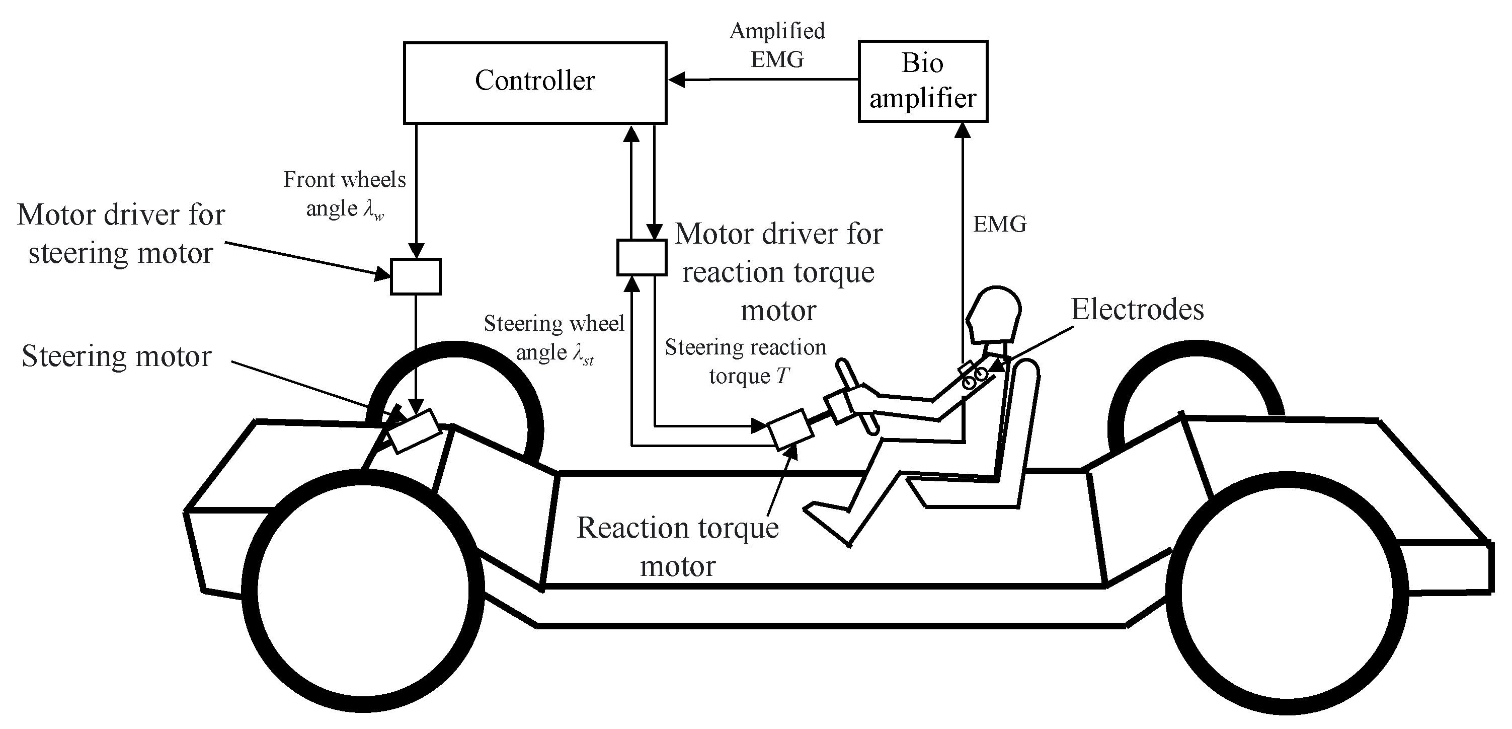
A steer-by-wire system is a system that transmits steering motions by means of electrical signals. As shown in Figure 1, a steering reaction torque motor directly connected to the steering wheel detects the angle of the steering wheel and transmits the information to the steering motor that steers the front wheels via a motor driver and controller. Our research group has proposed an active steering wheel system that provides an appropriate steering reaction torque and steering gear ratio for each driver through a steering reaction torque motor by inputting surface electromyogram (EMG) and joint movements into this controller.
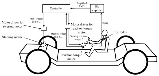
Figure 1.
Schematic of active steering wheel system.
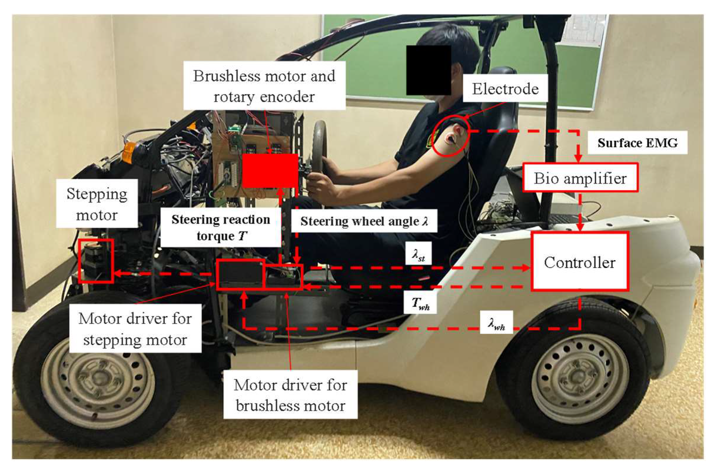
Figure 2 illustrates the experimental vehicle equipped with an active steering wheel system. COMS (ZAD-TAK30-BS, Toyota Auto Body Co., Ltd., Aichi, Japan), which is an ultra-compact electric vehicle manufactured by Toyota Auto Body, was selected as the experimental vehicle. A stepping motor (ARM98SAK-PS10, Oriental Motor Co., Ltd., Tokyo, Japan) was connected to the rack-and-pinion gear that is connected to the front wheels, and a brushless motor with a rotary encoder (BXM6200-GFS motor, Oriental Motor Co., Ltd., Tokyo, Japan) was connected to the steering wheel. These motors are controlled by their respective motor drivers and controllers, that is, the DSP (Digital Signal Processor). The DSP (DSP7101A, iBIS, MIS Co, Ltd., Tokyo, Japan) control system can be modified using a PC, and a Bio Amp (ML132 preamplifier AD Instruments, Sydney, Australia) can be installed to acquire the driver’s surface EMG in real time and incorporate it into the control system. When this system is implemented, it is not realistic to attach electrodes and cables to the driver’s skin to measure the surface EMG. However, in order to determine what kind of biological information should be fed back, it is necessary to clarify the burden of the driver through the EMG and analysis model.
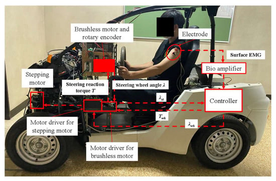
Figure 2.
Experimental vehicle equipped with an active steering wheel system.
3. Examination of the Effect of Changes in the Slide Adjustment on Steering Burden
3.1. Methods and Conditions for Evaluation of Steering Burden Using Surface EMG
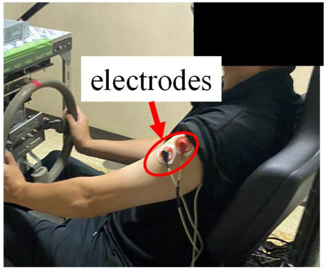
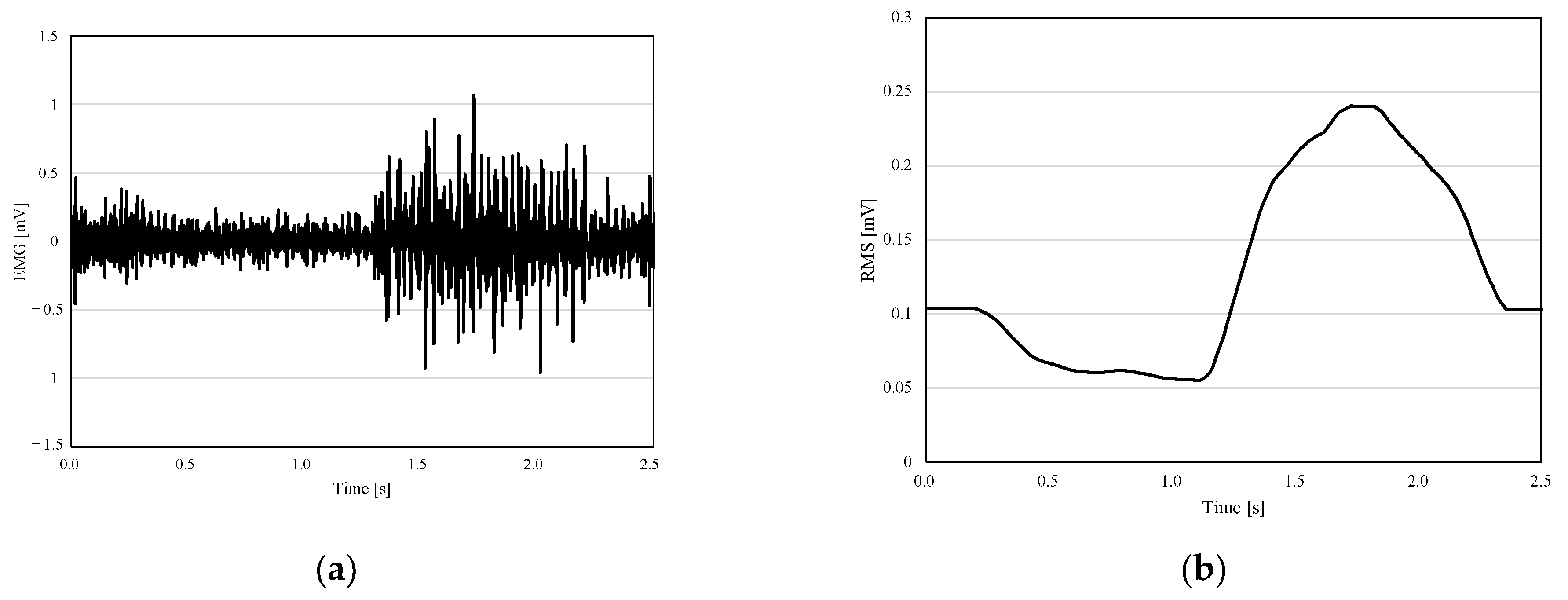
In an active steering wheel system, it is necessary to clarify the effect of changes in the driving position caused by changes in the amount of slide adjustment by the driver on the steering burden. We measured the surface EMG in the anterior deltoid to investigate the trend of the steering burden when the driving position is changed by the slide adjustment. Surface EMG is measured by electrodes attached to the skin just above the target muscle. The anterior deltoid is a muscle of the shoulder joint that is most active during steering operation, and it is known that the amount of activity tends to coincide with the feel of burden during steering operations [5]. The position of the electrode is shown in the Figure 3. The surface EMG was amplified using a Bio Amp (ML132 preamplifier, AD Instruments, Sydney, Australia), (high pass, 350 Hz; lowpass, 10 Hz), and then passed through an A/D converter (PowerLab ML825 2125, AD Instruments, Sydney, Australia). These experimental devices are connected to electrodes. In addition, the Root Mean Square (RMS) waveform was calculated by the original waveform of the EMG measured at 4 kHz. Because of the original waveform with the amplitude shown in Figure 4a, it is difficult to evaluate the amount of muscle activity. Therefore, the RMS was calculated using Equations (1) and (2).
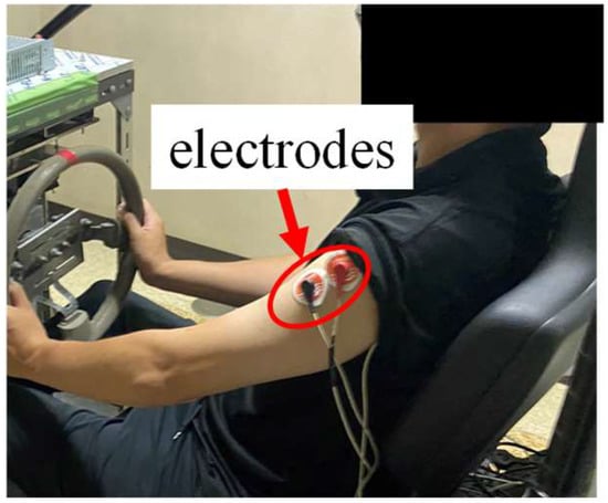
Figure 3.
The position of the electrodes.
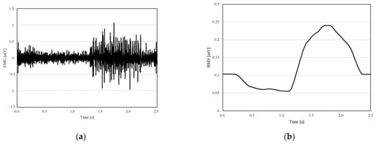
Figure 4.
Muscle activity by the surface EMG: (a) results of the original EMG; (b) RMS results.
Figure 4b shows the waveform processed by the RMS. In this experiment, the RMS was calculated every 0.1 s in the 0.1 s interval. Since the EMG was measured at 4 kHz, the value of N was 400 in Figure 4b. The processed RMS is used to evaluate the amount of muscle activity by calculating %MVC. Equation (3) shows the formula for deriving %MVC.
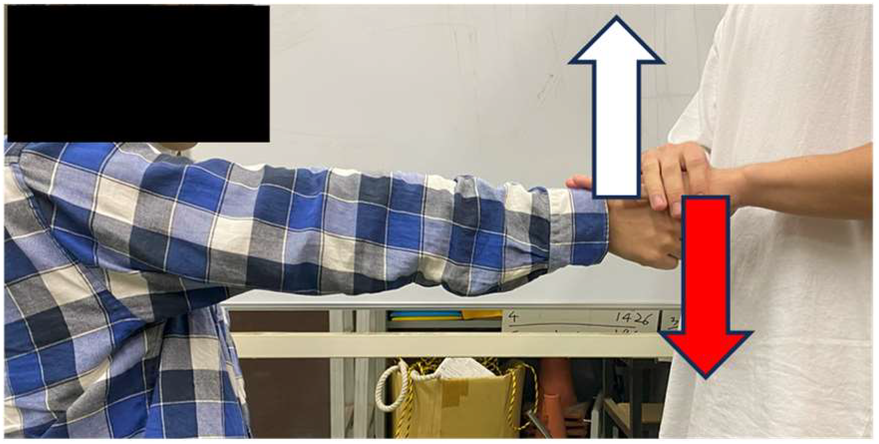
V is the RMS during steering operations, and MVC is the Maximum Voluntary Contraction, which indicates the RMS when the target muscle is exerting its maximum muscle force. The method of measuring the MVC is shown in Figure 5. The participant held his/her fist up vertically with maximum force and asked another person to restrain his/her fist. The MVC was measured for 5 s, and the maximum value at this time was taken as the MVC.
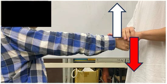
Figure 5.
Method of measuring the MVC of the anterior deltoid.
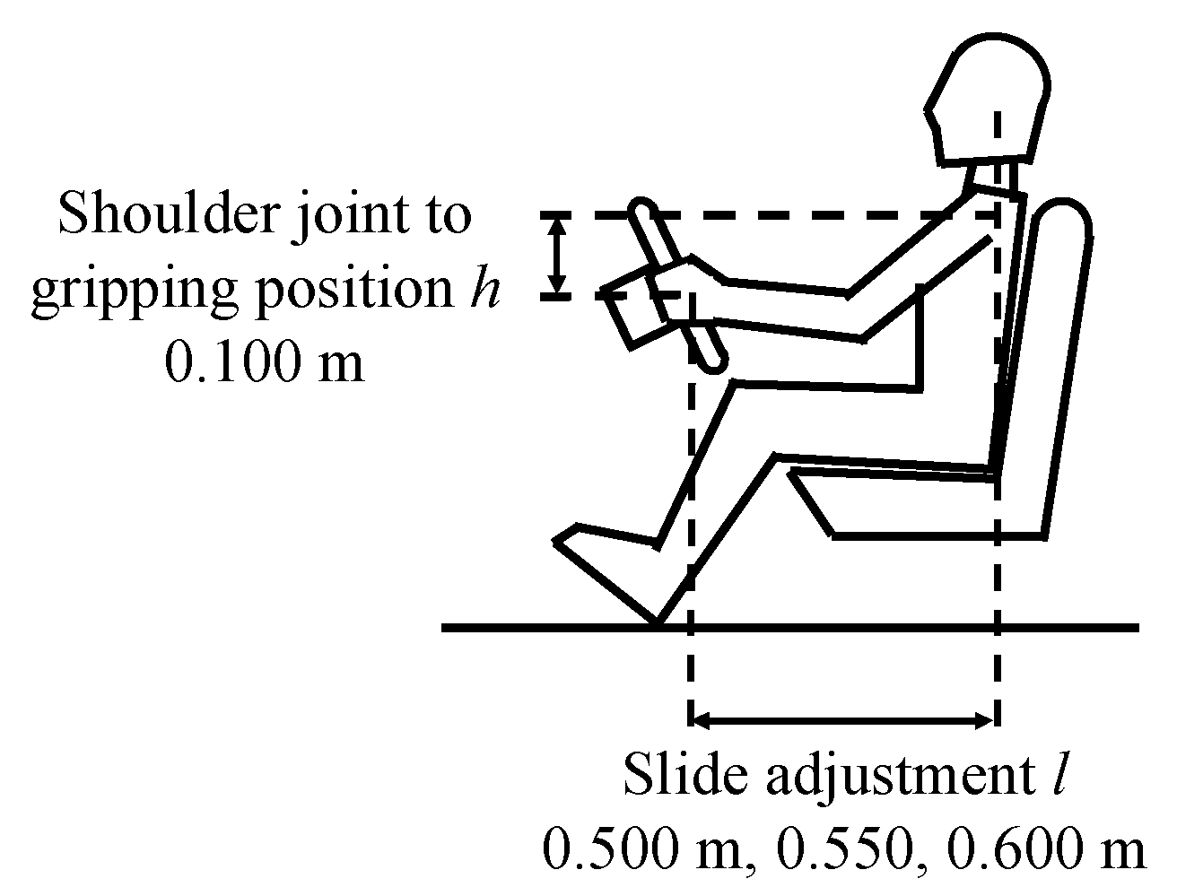
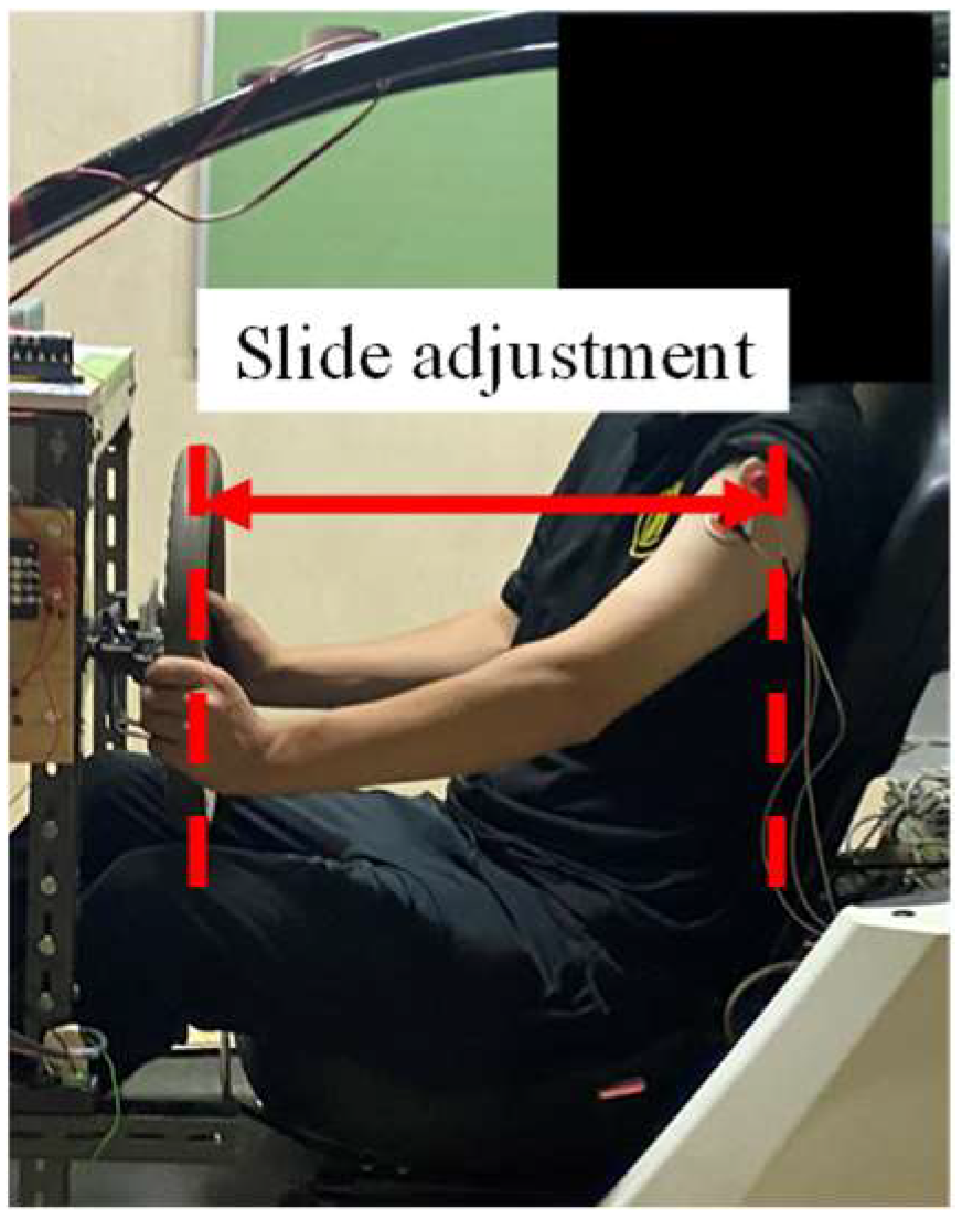
The condition of the driving position during steering operations is shown in Figure 6. The slide adjustment was changed in three patterns, and the participant was instructed to operate the steering wheel from 0° to 135° at each slide adjustment. The %MVC was calculated from the peak RMS at the time. The steering reaction torque was 2.7 Nm, which was measured in the experimental vehicle.
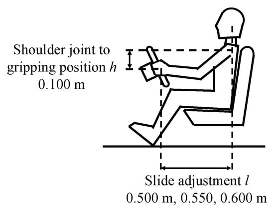
Figure 6.
Experimental conditions of the driving position.
3.2. EMG Measurement Results
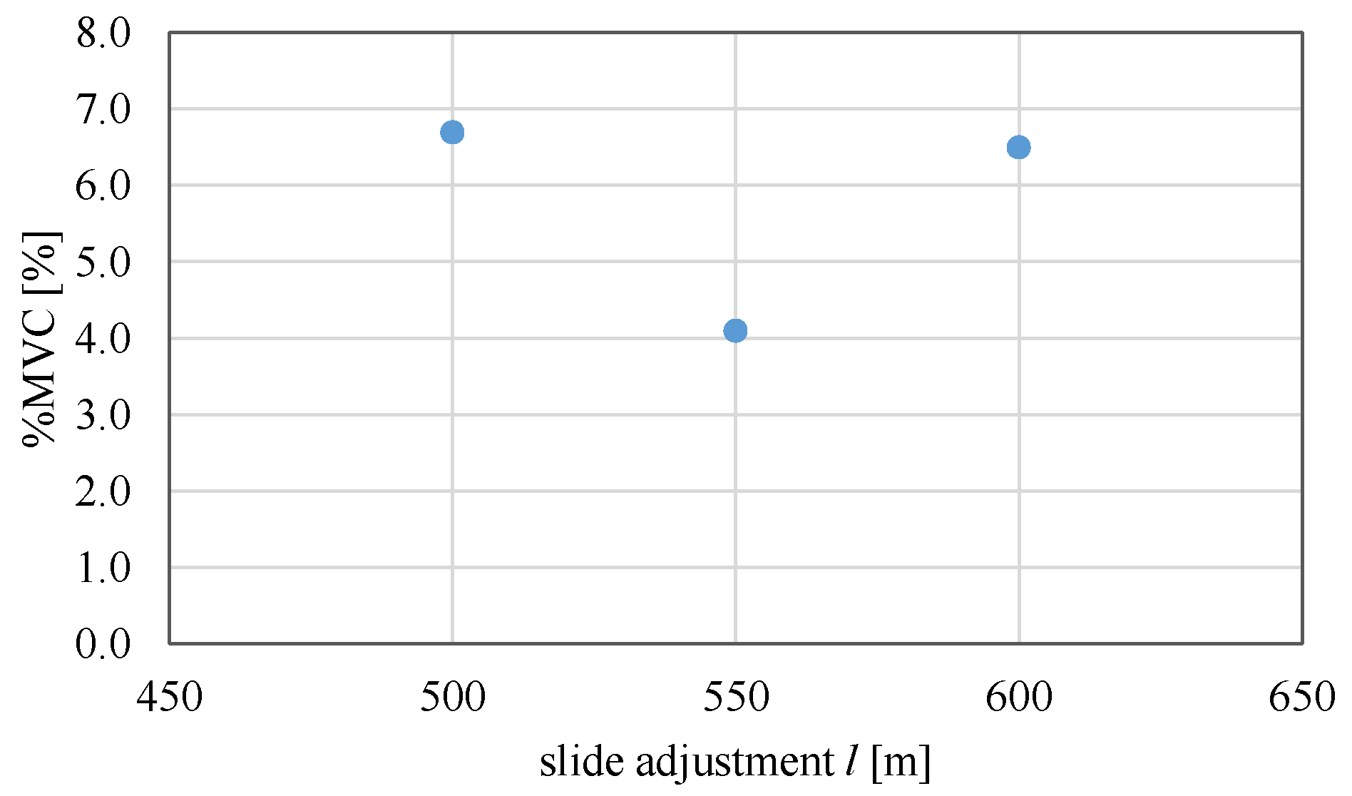
The peak %MVC during steering operations is shown in Figure 7 for each slide adjustment. The %MVC was reduced the most when the slide adjustment was 0.550 m. For the other two slide adjustments, the %MVC was about 7%, a difference of 3% from the most reduced value. Therefore, it was found that the steering burden increased when the slide adjustment was too small or too large.
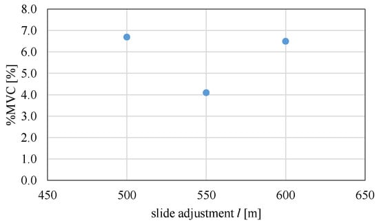
Figure 7.
Results of the %MVC for each slide adjustment.
4. Consideration of Steering Burden Using a Two-Dimensional Steering Analysis Model
4.1. Steering Analysis Model Conditions
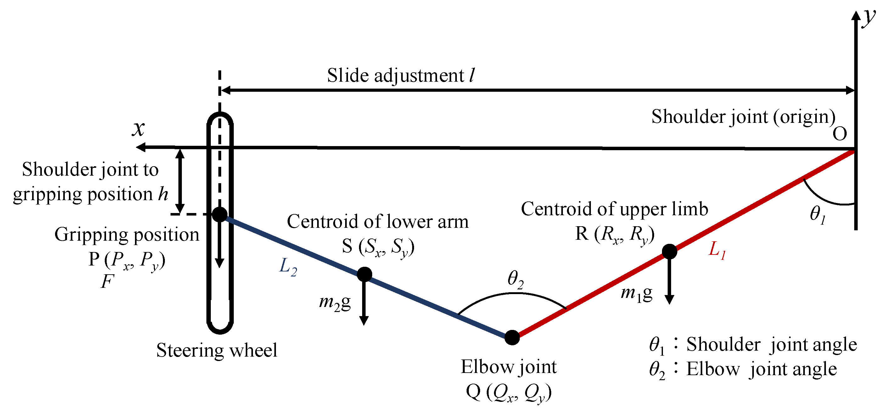
A steering analysis model of the driver was created to reproduce the driving position of the experimental vehicle shown in Figure 8, considering the range of motion of the steering wheel (Figure 9). The origin was set at the shoulder joint O, center of gravity of the upper arm at R, elbow joint at Q, center of gravity of the forearm at S and gripping position of the steering wheel at P. The length of the upper arm is L1, the length of the forearm is L2, the mass of the upper arm is m1, the mass of the forearm is m2 and the gravitational acceleration is g. Equations (4)–(7) were used to calculate each x-coordinate as follows. Px, Qx, Rx and Sx are the x-coordinates of the gripping position P, the elbow joint Q, the center of gravity of the upper arm R and the center of gravity of the forearm S, respectively.
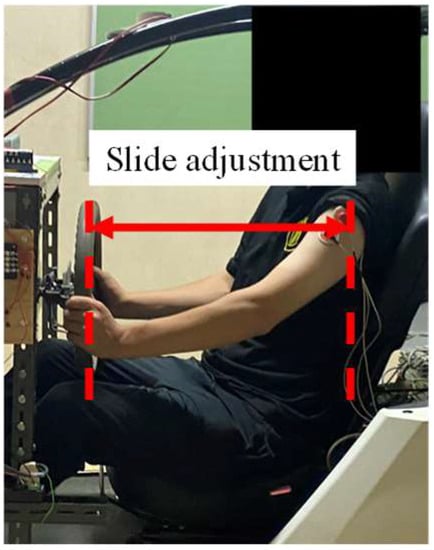
Figure 8.
Driving position changing system.
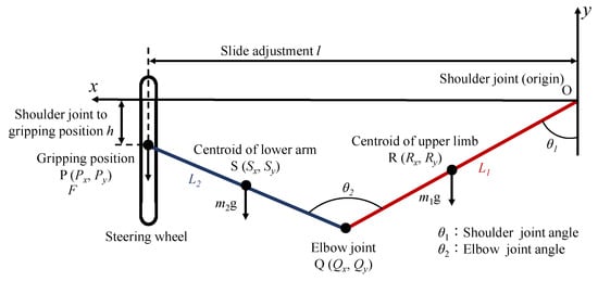
Figure 9.
Two-dimensional arm model schematic of a driver.
Here, 0.47 and 0.43 in Equations (6) and (7) are values indicating the position of the center of gravity of the arm [27,28].
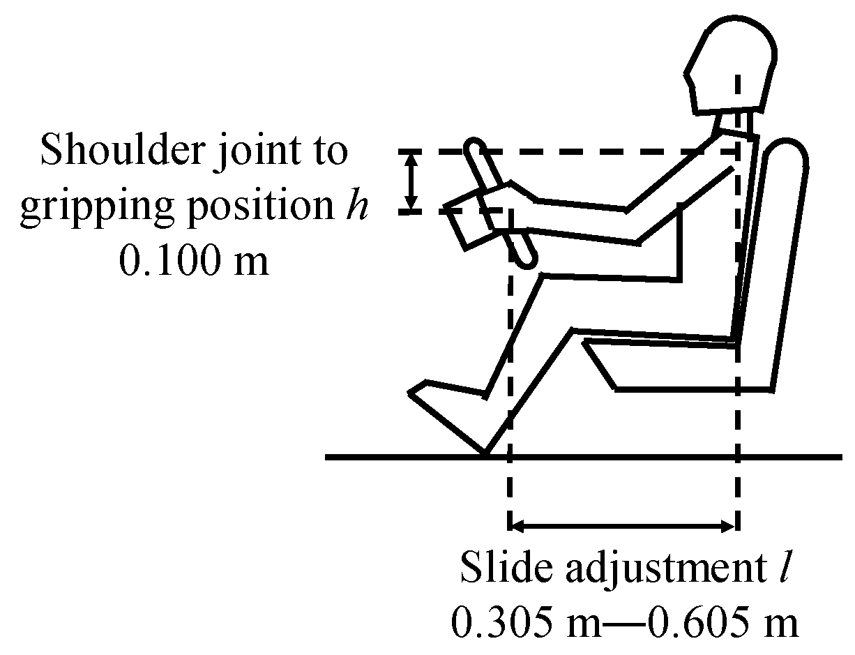
In this study, the burden on the shoulder joint was evaluated based on the changes in the driving position caused by changing the distance l from the shoulder joint to the steering wheel (slide adjustment) from 0.305 m to 0.605 m in the driving position, as shown in Figure 10. The steering reaction torque T was set to 2.7 N·m, which is the maximum torque generated by the COMS. The steering motion was reproduced by steering the steering wheel from 0° to 90°. The arm measurements of a 21-year-old male used in the analysis are listed in Table 1.
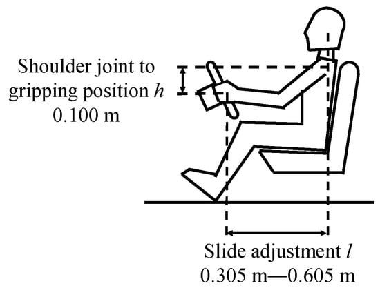
Figure 10.
Analysis conditions of the driving position.

Table 1.
Physique of the participant.
4.2. Muscle Burden Evaluation Using Joint Movements
Joint movements are commonly used as an index for evaluating muscle burden, and steering burden can be calculated by evaluating the muscle burden in the bending direction of the shoulder joint on the opposite side of the steering direction (push side) [13,29]. First, we calculated the joint movement Ms around the shoulder joint using Equation (8) to evaluate the steering burden.
It has been revealed that an evaluation of the steering burden is possible through the muscle activity of the anterior deltoid [5,13,29]. Furthermore, since the shoulder joint movement Ms aligns with the tendency of the anterior deltoid muscle activity, the evaluation of the steering burden can be conducted using Ms [20].
Here, F denotes the steering reaction force of the steering wheel in Equation (9). Additionally, T is the steering reaction torque and r is the steering wheel radius.
Then, T is 2.7 N·m and r is 0.1725 m. These values were measured on the experimental vehicle.
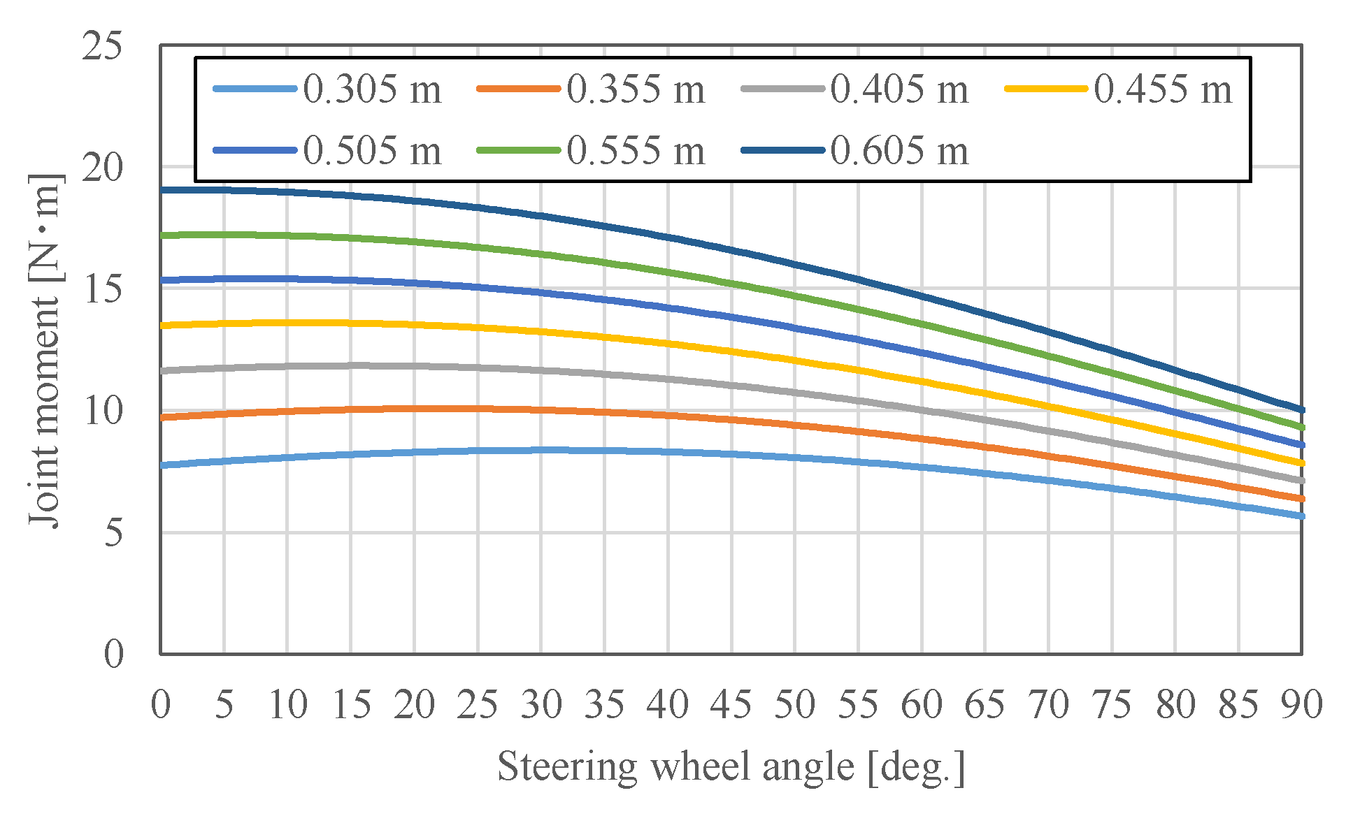
The joint movements calculated for each distance (slide adjustment) l, from the shoulder joint to the steering wheel, are illustrated in Figure 11. In this analysis, the joint movement generated at the shoulder joint O decreased with an increase in the steering wheel angle. This is because the force F, due to the steering reaction torque in the vertical direction of the steering wheel, decreases with an increase in the steering wheel angle, owing to the two-dimensional nature of the analysis. The force F was at the maximum value at a steering wheel angle of 0°, so the joint movement was at the maximum value. At any steering wheel angle, as the distance from the slide adjustment increases, the arm movement from the shoulder joint O to the center of gravity increases, thereby increasing the shoulder joint movement and the steering burden.
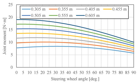
Figure 11.
Shoulder joint movement for different slide adjustments.
4.3. Effect of Joint Angle on the Shoulder Joint
The position with the lowest shoulder joint movement is at 0.305 m, where the slide adjustment l is at the minimum value. However, this position is assumed to be cramped, and it is difficult to operate the steering wheel in an actual driving position. Therefore, the amount of change in the joint angle was calculated to determine how the shoulder joint moved during the steering operations.
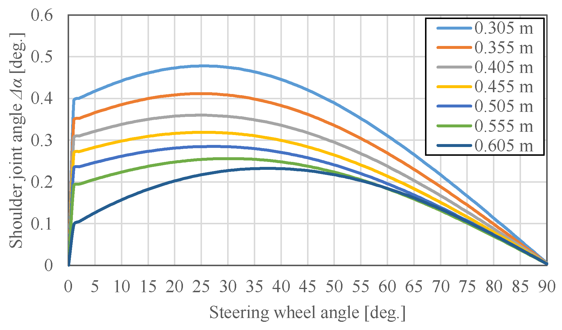
Figure 12 shows the shoulder joint angle Δα, which changes per degree of steering wheel angle. The joint angle also decreases with an increase in the amount of steering, owing to the two-dimensional nature of the joint angle. In addition, Δα is 0 at 90° for all l because the maximum steering motion was limited to 90°. Δα reached its maximum value at 0.305 m, the smallest slide adjustment, and decreased as the slide adjustment increased. In addition, Δα decreased sharply at 0.605 m, though Δα was almost identical to 0.555 m from a steering angle of 55°. Δα reached its peak at a steering wheel angle of 25° from 0.350 m to 0.505 m. However, from 0.555 m to 0.605 m, the steering wheel angle at the peak value increased. From these results, it is assumed that the shoulder joint angle variation Δα becomes larger as the slide adjustment becomes smaller, resulting in an increased steering burden. However, as the steering wheel angle increased, the difference in shoulder joint angle Δα for each slide adjustment became smaller.
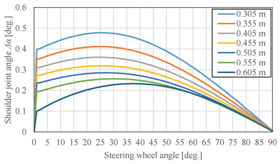
Figure 12.
Shoulder joint angle for different slide adjustments.
4.4. Muscle Burden Evaluation Using Shoulder Joint Power
Based on the evaluation, a longer and shorter l indicate a greater steering burden in terms of joint movement and angle, respectively. However, it is difficult to estimate which position has the most reduced burden for the driver using either of these methods. In addition, the amount of muscle exertion differs depending on the steering wheel angular velocity because it is not necessarily constant. Therefore, the shoulder joint power used for the body movement analysis was calculated. Joint power represents the work rate per unit time and can be used to estimate the approximate muscle activity. The joint power W is obtained by the product of the angular velocity of the joint and joint movement, as shown in Equation (10).
Here, T is the time per shoulder joint angle Δα, and the steering wheel angular velocity is 45°/s.
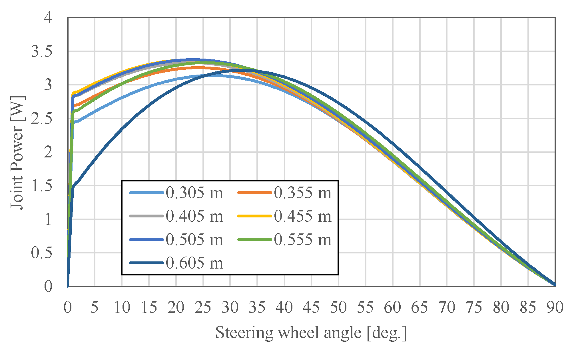
Figure 13 shows the results of the joint power for each slide adjustment. Values of 0.305 m and 0.605 m showed a decrease in joint power at the minimum and maximum slide adjustments.
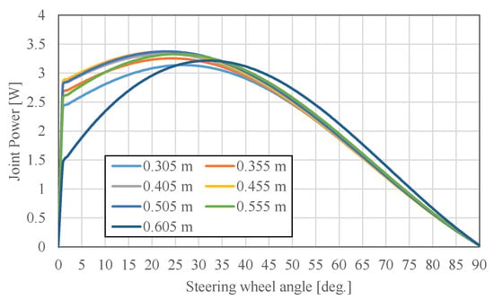
Figure 13.
Shoulder joint power for different slide adjustments.
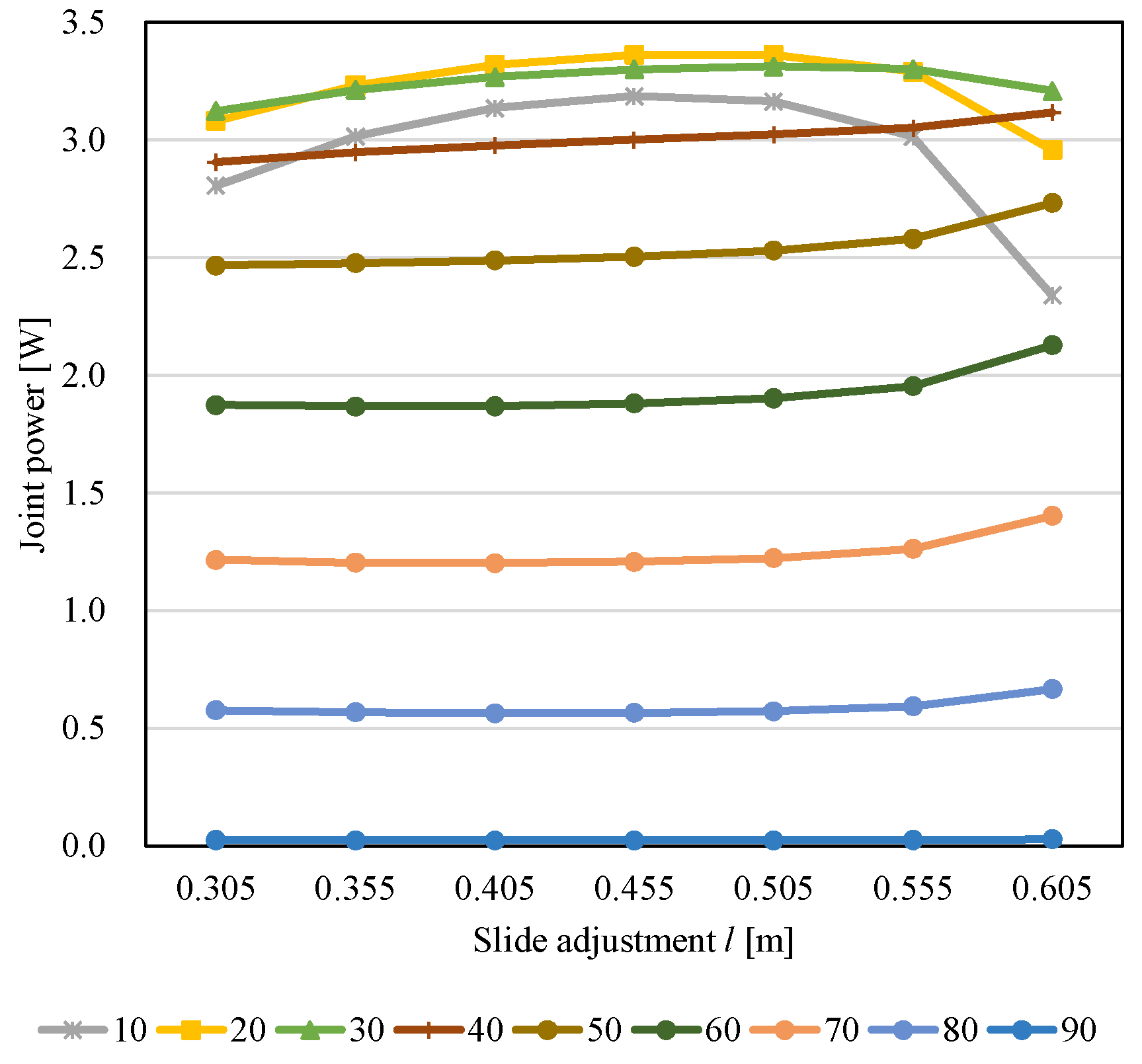
However, no other phenomena are observed. Therefore, Figure 14 illustrates the calculated joint power for different steering wheel angles. From a steering wheel angle of 40° to 80°, the shoulder joint power increased with an increase in the slide adjustment, and in Section 4.2, it was shown that shoulder joint movement increased with an increase in slide adjustment at all steering wheel angles. However, since the shoulder joint angle Δα was almost the same with the increasing steering wheel angle, the shoulder joint power showed the same trend as the shoulder joint movement.
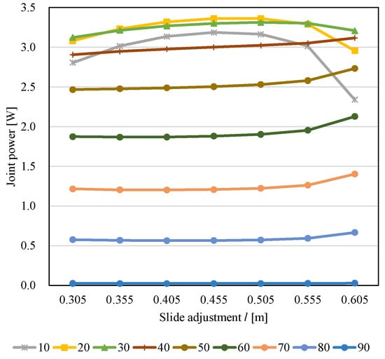
Figure 14.
Shoulder joint power for different steering wheel angles.
A different trend was observed from 10° to 30°. They showed a decrease in joint power at 0.305 m and 0.605 m, with a peak value around 0.455 m. Especially at 0.605 m, the shoulder joint power decreased rapidly. This is thought to be due to the shoulder joint angle Δα. For a steering wheel angle of 10° to 30°, the shoulder joint power rapidly decreased at 0.605 m because there was almost no change in the joint angle Δα. Thus, the shoulder joint must exert power without moving, and the joint movement Ms is the largest in this position.
At 0.305 m, the joint power is low because the joint movement Ms is small; however, the driver must move the shoulder joint more because the shoulder joint angle movement is largest in this range; therefore, the driving position is not considered to be less burdensome. In addition, even though the steering reaction torque remains the same, the movement generated at the shoulder joints is small, and the driver may feel that the steering reaction torque is light because the shoulder joints must be moved further, which may impair the driver’s steering feel.
For steering wheel angles greater than 40°, a trend of increasing power with increasing l was observed. It is difficult to estimate whether the driver feels burdened because the joint movement is large, and the joint angle has minimal changes. The trend then decreased as the steering wheel angle increased. This is because the steering reaction force F, generated in the vertical direction of the rotating steering wheel, decreases in the y-axis direction when the steering wheel angle increases. Moreover, the joint movement generated in the shoulder decreases more than it does. In addition, the tendency for the joint power to decrease with either too large or too small a slide adjustment was consistent with a trend in muscle activity in the anterior deltoid, where the degree of steering burden can be assessed. These results indicate that the joint power can be used to evaluate the steering burden based on the driving position when the steering wheel angle is 30° or less.
5. Conclusions
A two-dimensional steering model was created to evaluate the steering burden and estimate the appropriate driving position for each driver’s physique. In this study, the effects of varying the slide adjustment on the steering burden were examined. First, the muscle burden on the anterior deltoid was evaluated with different amounts of slide adjustments. It has been clarified that the amount of muscle activity in the anterior deltoid can be used to evaluate the steering burden. Therefore, the steering burden was evaluated from the amount of muscle activity using the %MVC from the measurement of the surface EMG of the anterior deltoid. The results showed that either too large or too small a slide adjustment increased the burden. Secondly, joint movements were calculated for each slide adjustment using the upper limb burden model. As a result, the joint movements increased with an increase in the amount of slide adjustment. This is because the distance between the center of gravity and the shoulder increased, and the movement of the arm increased. The smallest slide adjustment is the appropriate position for evaluating the joint movement. However, if the actual slide adjustment is too small, the driver’s position will be too cramped.
Therefore, we calculated the shoulder joint angle Δα from the upper limb burden model. The calculation result of Δα decreased as the slide adjustment decreased. As a result, it was clarified that the larger the slide adjustment, the more the steering motion was performed without moving the shoulder joint. In addition, unlike the joint movement, Δα converged at 0 as the steering wheel angle increased. Therefore, the more the steering wheel angle increases, the more difficult it becomes to evaluate the steering burden for each slide adjustment.
Consequently, it was difficult to evaluate the point with only the joint movement or joint angle where the steering burden worsens. This is because the phenomena occurring in the shoulder joint in the steering operation cannot be understood by the joint movement and angle alone. Therefore, by considering the joint movements and angles simultaneously using joint power, it is possible to estimate the driving position that causes burden, owing to the driver’s physique. Shoulder joint power was calculated using the calculated joint movements and joint angles. These results showed that joint power decreased at the maximum and minimum slide adjustment and increased at the intermediate slide adjustment. Therefore, when the joint power decreased, either the joint movement or joint angle increased, and the trade-off relationship between these can be evaluated. On the other hand, for steering wheel angles of 40° or greater, the joint power increased with an increasing slide adjustment. This is because the difference in the joint angle for each slide adjustment becomes small as the steering wheel angle increases. The differences in joint movements were also small as the steering wheel angle increased. Due to these effects, it is difficult to evaluate the joint power when the steering wheel angle increases.
Since only the vertical direction was considered in this model, the vertical power and joint angles decrease as the steering wheel angle increases for steering operations that involve a circular motion. Therefore, the joint power could not be evaluated at steering wheel angles of 40° or greater. However, the anterior deltoid is mainly involved in vertical movement. Thus, it was found that the joint power and surface EMG were consistent up to 30°, where the vertical component was large.
This model will be converted to a three-dimensional model in the future to investigate the steering burden caused by the driving position in the steering wheel angle range of 0° to 90°. The present study clarified the driving position in which the steering burden worsens. However, the appropriate joint angles and joint movements are affected by the driver’s muscle mass and other factors in the most appropriate driving position. The estimation method in this study presented the driving position that should not be taken based on the arm length, and an active steering wheel system will be constructed by feeding back biological information to the steering system.
Author Contributions
Conceptualization, D.U. and T.N.; methodology, D.U.; software, J.K. and A.E.; validation, I.K.; formal analysis, T.K. and K.O.; investigation, D.U. and T.K.; resources, T.N. and K.I.; data curation, H.K. and K.I.; writing—original draft preparation, D.U.; writing—review and editing, T.N.; visualization, J.K.; supervision, H.K.; project administration, A.E.; funding acquisition, T.N. All authors have read and agreed to the published version of the manuscript.
Funding
This research received no external funding.
Data Availability Statement
Data sharing is not applicable to this article.
Acknowledgments
We would like to show our appreciation to Mohamad Heerwan Bin Peeie and Xiaojun Liu.
Conflicts of Interest
The authors declare no conflict of interest.
References
- Kitahara, K.; Haramiishi, Y.; Mouri, H. Proposal of New Steering System Considering the Direction of Upper Limb Motion. Trans. Jpn. Soc. Mech. Eng. Ser. C 2013, 79, 3327–3334. [Google Scholar] [CrossRef]
- Tanimoto, Y.; Watanabe, M.; Kono, R.; Hirota, C.; Takasaki, K.; Kono, K. Aging changes in muscle mass of Japanese. Nippon. Ronen Igakkai Zasshi. Jpn. J. Geriatr. 2010, 47, 52–57. [Google Scholar] [CrossRef] [PubMed]
- Tamida, K.; Nihei, M.; Shino, M.; Kamata, M. 2208 An Analysis of the Elderly on Their Driving Behavior Based on the Multimodal Data During the Course Driving. Proc. Transp. Logist. Conf. 2010, 19, 283–286. [Google Scholar] [CrossRef]
- Liu, X.; Ayato, E.; Ikeda, K.; Peeie, M.H.B.; Kato, H.; Narita, T. Evaluation of the Burden of Steering Wheel Switching Operation in an Ultra-Compact EV with Steer-by-Wire System. Proc. Sch. Eng. Tokai Univ. Ser. E 2018, 43, 24–30. [Google Scholar]
- Umemoto, T.; Liu, X.; Narita, T.; Kato, H.; Moriyama, H. Steer-by-Wire System for Ultra-Compact Electric Vehi-cle—Fundamental Consideration on the Burden of the Push Side Upper Arm Using EMG of Anterior Deltoid. J. Jpn. Soc. Appl. Electromagn. Mech. 2017, 25, 155–161. [Google Scholar]
- Sterthoff, J.; Henze, R.; Küçükay, F. Vehicle handling improvements through Steer-by-Wire. Automot. Engine Technol. 2021, 6, 91–98. [Google Scholar] [CrossRef]
- Kakinuma, T.; Shino, M.; Kamata, M. Proposal on Steering System Based on Relationship between, Gear Ratio and Reaction Torque Control at Low-Speed Region. Proc. Transp. Logist. 2006, 52, 317–320. [Google Scholar]
- Tamakawa, S.; Mouri, H.; Kazama, K.; Sato, K. 3304 An investigation on driving easiness of bar type steering in high speed range. Proc. Transp. Logist. Conf. 2015, 63, 15. [Google Scholar] [CrossRef]
- Matsuoka, K.; Tachiwana, S.; Doi, S.; Wada, T. The Effect of Smaller Amount of Speed-depended Steering Control for Driving Behaviors. Proc. Conf. Chugoku-Shikoku Branch 2008, 46, 495–496. [Google Scholar] [CrossRef]
- Suzuki, R.; Soma, H.; Shimoyama, O.; Abe, M.; Sakuma, T. Effect of Information about Change of Steering Gear Ratio on Driver Behavior. Proc. Transp. Logist. Conf. 2007, 16, 275–278. [Google Scholar] [CrossRef]
- Kitahara, K.; Haramiishi, Y.; Mouri, H. 1205 Development of Low Gear Ratio Steering System without Changing the Hand Holding Position. Proc. Transp. Logist. Conf. 2013, 22, 235–236. [Google Scholar] [CrossRef]
- Kuramori, N.; Koguthi, N.; Kamijo, M.; Sadoyama, T. Study on Driving Ease Evaluation Focusing on Muscular Activity of Driver. Trans. Soc. Automot. Eng. 2007, 61, 116–121. [Google Scholar]
- Kuramori, A.; Sakai, D.; Kamaji, M. Study on Driving Fatigue Evaluation by Using Driver’s Electromyogram. Trans. Soc. Automot. Eng 2010, 41, 489–493. [Google Scholar]
- Dickerson, C.R.; Martin, B.J.; Chaffin, D.B. Predictors of Perceived Effort in the Shoulder during Load Transfer Tasks. Ergonomics 2007, 50, 1004–1016. [Google Scholar] [CrossRef] [PubMed]
- Yang, Y.; Liu, Y.; Wang, M.; Ji, R.; Ji, X. Objective Evaluation Method of Steering Comfort based on Movement Quality Evaluation of Driver Steering Maneuver. Chin. J. Mech. Eng. 2014, 27, 1027–1037. [Google Scholar] [CrossRef]
- Pick, A.J.; Cole, D.J. Measurement of Driver Steering Torque Using Electromyography. J. Dyn. Syst. Meas. Control. 2006, 128, 960–968. [Google Scholar] [CrossRef]
- Liu, Y.; Ji, X.; Ryouhei, H.; Takahiro, M.; Lou, L. Function of Shoulder Muscles of Driver in Vehicle Steering Maneuver. Sci. China Technol. Sci. 2012, 55, 3445–3454. [Google Scholar] [CrossRef]
- Matsugaura, S.; Nishimura, H.; Omae, M.; Shimizu, H. Development of a Driver-monitoring Vehicle Based on an Ultra Small Electric Vehicle. J. Asian Electr. Veh. 2005, 3, 757–762. [Google Scholar] [CrossRef]
- Shao, K.; Zheng, J.; Huang, K. Robust active steering control for vehicle rollover prevention. Int. J. Model. Identif. Control. 2019, 32, 70–84. [Google Scholar] [CrossRef]
- Uchino, D.; Hirai, T.; Arai, S.; Ikeda, K.; Kato, T.; Liu, X.; Endo, A.; Kato, H.; Narita, T. Active Steering Wheel System for Ultra-Compact Mobility Vehicles: Operability Evaluation with Steering Burden in Various Drivers. J. Robot. Mechatron. 2021, 33, 1169–1177. [Google Scholar] [CrossRef]
- Liu, X.; Uchino, D.; Ikeda, K.; Endo, A.; Bin Peeie, M.H.; Narita, T.; Kato, H. Driving Assist System for Ultra-Compact EVs―Fundamental Consideration of Muscle Burden Owing to Differences in the Drivers’ Physiques. Actuators 2018, 7, 44. [Google Scholar] [CrossRef]
- Andreoni, G.; Santambrogio, G.C.; Rabuffetti, M.; Pedotti, A. Method for the analysis of posture and interface pressure of car drivers. Appl. Ergon. 2002, 33, 511–522. [Google Scholar] [CrossRef] [PubMed]
- Tamai, T.; Yamazaki, N. Operability and Physical Factors of Forward-Bent Driving Posture. Jpn. J. Ergon. 2006, 42, 180–181. [Google Scholar]
- Reed, M.P. Statistical and Biomechanical Prediction of Automobile Driving Posture. Ph.D. Thesis, University of Michigan, Ann Arbor, MI, USA, 1998. UMI nubber 9825331. [Google Scholar]
- Reed, M.P.; Manary, M.A.; Flannagan, C.A.C. Effects of Vehicle Interior Geometry and Anthropometric Variables on Au-tomobile Driving Posture. J. Hum. Factors Ergon. Soc. 2000, 42, 541–552. [Google Scholar] [CrossRef]
- Ito, K.; Hayakawa, S.; Goto, S.; Tsuda, S.; Ikeura, R.; Hayakawa, T. Decreasing method of increasing fatigue in driving focused on driving posture change with lumber support. IEEJ Trans. Electron. Inf. Syst. 2015, 135, 513–519. [Google Scholar] [CrossRef]
- Matsui, H. Determination of Center of Gravity of Human Body in Various Postures. Jpn. J. Phys. Educ. Health Sport Sci. 1956, 2, 65–76. [Google Scholar] [CrossRef]
- Ogawa, K. Evidence-Based Nursing Ergonomics and Body-Mechanics, 2nd ed.; Tokyo Denki University Press: Tokyo, Japan, 2003; p. 23. [Google Scholar]
- Yoshida, T.; Hase, K.; Obinata, G.; Hada, M. Analysis of Steering Operation Using a 3-Dimentional Musculo-Skeletal Model of the Upper Extremities and Evaluation about the Design Parameters of Steering Wheels. J. Soc. Biomech. 2010, 34, 41–52. [Google Scholar] [CrossRef]
Disclaimer/Publisher’s Note: The statements, opinions and data contained in all publications are solely those of the individual author(s) and contributor(s) and not of MDPI and/or the editor(s). MDPI and/or the editor(s) disclaim responsibility for any injury to people or property resulting from any ideas, methods, instructions or products referred to in the content. |
© 2023 by the authors. Licensee MDPI, Basel, Switzerland. This article is an open access article distributed under the terms and conditions of the Creative Commons Attribution (CC BY) license (https://creativecommons.org/licenses/by/4.0/).

