Communication

Spin Polarization Crossing a Heterostructure of a Ferromagnetic/Semiconductor-Based Rashba Spin–Orbit Interaction: Tight Binding Approach

by
Aek Jantayod
1,2
1
Department of Physics, Faculty of Science, Naresuan University, Phitsanulok 65000, Thailand
2
Research Center for Academic Excellence in Applied Physics, Faculty of Science, Naresuan University, Phitsanulok 65000, Thailand
Physics 2025, 7(3), 29; https://doi.org/10.3390/physics7030029
Submission received: 24 April 2025 / Revised: 4 June 2025 / Accepted: 6 June 2025 / Published: 17 July 2025
(This article belongs to the Section Classical Physics)

Abstract

The spin polarization of current in a conventional ferromagnetic and semiconductor-based Rashba spin–orbit interaction (RSOI) in an infinite two-dimensional system and the electrical properties of the junction are described using the square lattice model. In particular, a suitable approach is devised to compute the particle transport characteristics in the junction, taking into consideration the interface quality. It is found that the spin polarization becomes strongly reliant on the spin-flip scattering potential at applied voltages close to the crossings of the semiconductor-based RSOI band. On the other hand, in the voltage near the middle band, the spin polarization of current is found to remain modest and not influenced by either the spin-flip or non-spin-flip scattering potentials.

1. Introduction

Spintronics, or spin-based electronics, seeks to create new technologies by utilizing the intrinsic spin of the electron in addition to its fundamental electrical charge. The goal of this discipline is to develop electronics that, in comparison to traditional charge-based electronics, are quicker, more efficient, and able to carry out innovative tasks [1,2,3,4,5,6]. A major milestone in spintronics was the discovery of tunneling magnetoresistance (TMR) in magnetic tunnel junctions (MTJs), where two ferromagnetic (FM) layers are separated by a thin insulating barrier [7]. In these systems, the resistance depends on whether the magnetizations of the FM layers are parallel or antiparallel. This phenomenon has enabled high-performance spintronic applications such as magnetic random-access memory (MRAM) and non-volatile logic devices [7,8,9]. However, conventional MTJ-based devices face several limitations, including low spin injection efficiency into semiconductors due to conductivity mismatch, sensitivity to defects in the tunnel barrier, and scaling challenges at the nanoscale [9,10]. As a result, attention has shifted toward alternative device structures, especially those based on FM/semiconductor (FM/SC) and FM/SC/FM heterojunctions. These structures provide higher flexibility for generating and controlling spin-polarized currents.
In recent years, two-dimensional (2D) materials have attracted high attention for their potential in spintronic applications. Among those materials, van der Waals (vdW) ferromagnets such as Fe3GeTe2 (FGeT) [11,12,13] and Fe3GaTe2 (FGaT) [14] are of particular interest since they can retain ferromagnetic ordering even in monolayer form. When combined with 2D semiconductors such as WSe2 [15], MoS2 [16], or InSe [17], those semiconductors form ultra-thin FM/SC heterostructures, and have shown significant magnetoresistance (MR) and spin-dependent transport phenomena. The atomically sharp interfaces, strong spin–orbit interaction (SOI), and gate-tunability of these materials make them highly suitable for low-power and flexible spintronic devices.
Among various spin transport phenomena, MR in vdW FM/SC junctions has become an essential topic of study. Particularly, the TMR in these junctions can be strongly influenced by external conditions, such as applied bias voltage or barrier thickness. In some cases, MR sign inversion has been observed and can be controlled electrically or structurally [15,16,17]. For example, the FGeT/WSe2/FGeT spin valve structure shows a transition from negative to positive MR as the WSe2 barrier becomes thinner, which is attributed to a Δ-symmetry filtering effect in orbital tunneling. Similar voltage-controlled MR sign changes have also been reported in FGeT/MoSe2/FGeT [17] and FGaT/hBN(hexagonal boron nitride)/FGaT [14] junctions. These findings highlight the importance of the spin-resolved density of states and tunneling symmetry at finite energy levels in determining spin transport behavior in vdW heterostructures. Moreover, in such 2D semiconductor systems, Rashba spin–orbit interaction (RSOI) plays a central role [18,19]. In materials with structural inversion asymmetry, RSOI causes momentum-dependent splitting of spin states, which enables manipulation of spin polarization via external electric fields, making it a critical phenomenon for controlling spin currents in various devices. This paradigm shift opens new pathways for realizing scalable, high-speed, and energy-efficient spintronic devices integrated with semiconductor technology such as spin transistors [20,21], spin valves [22], and spin-based logic devices [23].
Naturally, characteristics for the transportation of both charge and spin across the interface in heterojunctions made of different materials are significantly influenced by interfacial scattering at the junction. For instance, the electrical efficiency of the junction can be enhanced by experimentally producing a normal spin scattering at the contact [24]. Moreover, the implantation of magnetic impurities at the junction can give rise to a spin-flip scattering potential [25,26,27,28,29]. Equally, increasing the value of normal spin scattering and spin-flip scattering can enhance junction efficiency, maximizing conductance in junctions, as discussed in Refs. [30,31,32]. The interfacial scattering in magnetic tunnel junctions is crucial for determining charge and spin transport properties.
Different views on particle and spin crossing in materials with RSOI have been developed, using the continuous model and the continuity equation at the junction [33,34,35,36,37,38,39]. These considerations, however, are predicated on the approach that the free electron model can propagate uncontrolled. A more accurate free electron model has been developed by considering the localization of electrons at the atomic levels within the lattice. An improved estimate for free particles has been developed. In other words, electrons in a solid are tightly bound to their parent atoms, and their wavefunctions can be approximated as linear combinations of atomic orbitals (LCAO) from neighboring atoms; while these features seem to be incompatible features, this is a tight-binding approximation.
In this study, the motion equation of a particle within a one-band tight-binding is used to theoretically evaluate the charge transport in FM/SC heterostructures based on RSOI. It is determined how to properly account for the impact of interfacial scattering on spin polarization. The simulation outcomes of both the hole and electron tunneling on the total energy band of the RSOI are extended to a 2D structure. At applied voltages close to the crossings of the RSOI band, it is discovered that the spin polarization becomes substantially dependent on the spin-flip scattering potential. Conversely, the spin polarization of the current is small in the half-filled band and is independent of the interfacial scattering potentials.

2. Model and Method

A plane for an infinite 2D square lattice (see Figure 1, upper) is used to describe the junction of a ferromagnetic and semiconductor-based RSOI. According to the free electron Hamiltonian, p 2 / 2 m * + λ ( σ 2 p x σ 1 p y ) , where m * and p are the electron effective mass and the electron momentum, respectively. The parameter λ denotes the strength of RSOI. The σ 1 , 2 are two first of the three Pauli spin matrices. Then, the Hamiltonian that describes the effect of Rashba interaction in an a × a lattice within only the nearest-neighbors hopping energy given by [36,37]
H R = n m σ ϵ n m σ μ T n m σ T n m σ t k n m σ T n + 1 , m σ T n m σ + T n , m + 1 , σ T n m σ + h . c .   t so n m σ σ T n + 1 , m σ ( i σ 2 ) σ σ T n m σ T n , m + 1 , σ ( i σ 1 ) σ σ T n m σ + h . c . ,
where the creation and annihilation operator of the electron at indices with spin up and down ( σ =   ) at the column n and the row m , are respectively represented by T n m σ and T n m σ , and ϵ n m σ is the energy on-site; t k = 2 / 2 m * a 2 , with the reduced Planck constant, is the nearest-neighbor hopping energy for a constant lattice a (see Figure 1, upper), μ is the chemical potential, and t so = λ / 2 a is the hopping energy of RSOI. The term “h.c.” denotes the hermitian conjugate.
Using the Fourier transform to calculate the energy spectrum, one obtains E ( k ) = E 0 ( k ) ± 2 t so sin 2 ( k x a ) + sin 2 ( k y a ) , with E 0 ( k ) = ( ϵ R μ ) 2 t k cos ( k x a ) + cos ( k y a ) , without spin–orbit interaction, where ϵ R is the on-site energy of RSOI. The signs + and − address the energy splitting of the RSOI and k x ( y ) is the wave vector. The dispersion of energy with a lattice model is displayed in Figure 1 (lower), which is a particular case for a ferromagnetic Fermi level that reaches the connection point of the “plus” and the “minus” branches of RSOI bands. The intersection of the plus and the minus branches occurs at the point ( k x = 0 , k y = 0 ) , which is called the first crossing point, and at the point ( k x = ± π / a , k y = 0 ) , which is called the second crossing.
E R 1 ( 0 , k y ) = ( ϵ R μ ) 2 t so sin ( k y a ) + t k ( 1 + cos ( k y a ) )
and
E R 2 ( π / a , k y ) = ( ϵ R μ ) + 2 t so sin ( k y a ) t k ( cos ( k y a ) 1 )
denote the energy levels to select the electronic wave functions of the particle and spin that can tunnel in the Rashba system. Then, E so bot top is the Rashba energy, which can be obtained from the spacing energy between the minimum (maximum) energy to the first (second) crossing point of the RSOI band.
Note that the hopping energy t N along the y -direction is set to be less than that along the x -direction, i.e., t N = 0.1 t N , with t N the nearest-neighbor hopping energy of FM, to ensure that quasiparticles are accessible for tunneling into a specific Rashba system at all k y .
Additionally, in the ferromagnetic region, Equation (1) reads [38]
H F M = n m σ ( ϵ n m σ ε ex M σ ^ μ ) T n m σ T n m σ t N n m σ ( T n + 1 , m σ T n m σ + T n , m + 1 , σ T n m σ + h . c . ) ,
where t N = t k , ε ex is the exchange Zeeman splitting energy and is set to ε ex = 0.1 t N , M is the magnetization, and σ ^ denotes the Pauli spin matrices. The expression for energy then reads E F M ( k ) = ( ϵ F M μ ± ε ex ) 2 t N cos ( k x a ) 0.1 cos ( k y a ) , where ϵ F M is the on-site energy of FM.
An injection of electrons from the ferromagnetic into a given RSOI system was assumed based on the BTK (Blonder–Tinkham–Klapwijk) model [39]. The model also assumed that the distinct entering states for two different cases in a ferromagnetic for up-spin and down-spin corresponded to the two different wave functions.
Φ F M , 1 k y ( n , m ) = e i q x a n 1 0 + e i q x a n r 1 r 1 e i k y m a , Φ F M , 2 k y ( n , m ) = e i q x a n 0 1 + e i q x a n r 2 r 2 e i k y m a ,
where q x = 1 a cos 1 ϵ F M E ( k ) μ ± ε ex 2 t N cos ( k y a ) 2 t N and the values of q x and k y are less than π / a , r j σ is the reflection amplitudes for the case j with spin- σ state.
There are three different energy levels of the electrical wave functions that are present on the semiconductor side:
For E < E R 1 0 , k y ,
Φ R k y ( n , m ) = e i k x + a n t j + 2 χ k x + a , k y a 1 + e i k x a n t j 2 χ k x a , k y a 1 e i k y m a ;
for E R 1 ( 0 , k y ) E E R 2 ( π / a , k y ) ,
Φ R k y ( n , m ) = e i k x + a n t j + 2 χ k x + a , k y a 1 + e i k x a n t j 2 χ k x a , k y a 1 e i k y m a ;
for E > E R 2 ( π / a , k y ) ,
Φ R k y ( n , m ) = e i k x + a n t j + 2 χ k x + a , k y a 1 + e i k x a n t j 2 χ k x a , k y a 1 e i k y m a ,
where χ k x ± , k y = i sin ( k x ± a ) + sin k y a sin 2 ( k x ± a ) + sin 2 k y a . The transmission amplitude in each case j is denoted by t j ± , and k x ± a is determined from the energy expression of RSOI; cos ( k x ± a ) = 1 2 κ ± κ 4 ζ , where κ = t k t k 2 + t so 2 E ( μ + ϵ R ) + 2 t k cos ( k y a ) , and ζ = t so 2 t k 2 + t so 2 ( 1 + sin 2 ( k y a ) ) 1 4 ( t k 2 + t so 2 ) ( E ( μ + ϵ R ) + 2 t k cos ( k y a ) ) 2 , and the minority and majority branch are represented by ± signs. Due to consideration with the translational symmetry in y -direction results in the wave vector momentum of k y which is equal to q y .
To determine the transmission ( t j + , t j ) and reflection ( r j + , r j ) amplitudes, the appropriate boundary conditions are computed after adding the potential barrier between the heterostructures:
Φ R k y ( 0 ) Φ F M k y ( 0 ) = 0 ,
t N Φ F M k y ( 1 ) T so Φ R k y ( 1 ) + V Φ R k y ( 0 ) = 0 ,
where V is the scattering potential, V = V V V V ; a spin-conserved (non-spinflip scattering) is V 0 = V = V , and the spin-flip scattering is V F = V = V , and T so = t k t so t so t k . While it is known that the strength of SOI can be modulated by external electric fields and interfacial conditions, such as the presence of a Schottky barrier, in this study the RSOI strength is fixed to a representative value. This approach enables us to isolate and systematically analyze the influence of interfacial scattering mechanisms, particularly non-spin-flip and spin-flip scattering, on spin-polarized transport.
The transmission ( T σ ) and reflection ( R σ ) probabilities can be used to calculate the current density along the x -direction using the Landauer formula,
J ( e V ) = G 0 π / 2 π / 2 d k y 0 e V d E T σ ( E ) f ( E e V ) f ( E ) ,
where G 0 = e 2 a 2 ( 2 π ) 2 , e denotes the charge of the electron, e V is the applied voltage, a 2 is the area of lattice network, and f ( E ) is a Fermi distribution function. Note that T σ ( E ) is the total transmission probability, which can be written in the form of total reflection probability as 1 R σ ( E ) . Thus, the differential conductance G ( e V ) d J / d V at zero temperature is
G σ ( e V ) = e 2 a 2 ( 2 π ) 2 π / 2 π / 2 [ 1 R σ ( E ) ] d k y .
To examine the spin imbalance created when the current reflects on the ferromagnetic side, one to take into account the spin polarization of current
P F M ( e V ) = G ( e V ) G ( e V ) G ( e V ) + G ( e V ) .
For all calculations in this paper, G σ = G σ / G 0 and G σ ( e V ) is a given spin direction of the conductance. In this study, the spin polarization of current in a ferromagnetic side is specifically pointed because the spin of the polarization represents up-spin and down-spin precisely.

3. Results and Discussion

This study investigates the effects of varying potential barrier heights at the interface of a FM/SC conductor junction (column n = 0 in Equation (1)) with RSOI on the spin polarization of the current. To simplify the analysis, it is assumed here that the energy band of the semiconductor with RSOI is initially empty. All calculations, t so is set to 0.04 t N . The primary spin polarization result is actually unaffected by the choices of parameters t so and t k . Here, spin-flip ( V F ) and non-spin-flip ( V 0 ) scattering potentials represent two key physical processes at the FM/SC interface affecting spin transport. Spin-flip scattering arises mainly from magnetic impurities, localized magnetic moments, or spin-dependent interactions arising from spin–orbit coupling and magnetic disorder within the material or at the interface [10,28,29,35]. Non-spin-flip scattering, on the other hand, is caused by structural defects and interface roughness that scatter electrons without changing spin orientation, influencing charge transport, and indirectly affecting spin coherence. These potentials effectively capture the influence of magnetic and nonmagnetic disorder, linking theoretical parameters to experimental material quality. Controlling these scattering mechanisms through interface engineering is thus crucial for optimizing spintronic device performance. So, the present study examines how the spin polarization of current is affected by the interface scattering potentials.
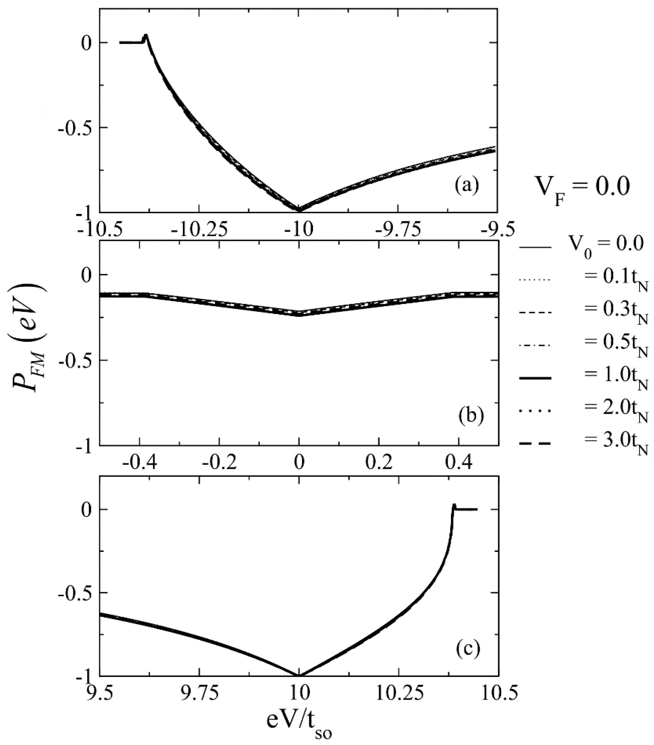
In Figure 2, spin polarization is shown as a function of the applied voltage with the barrier potential transparency considered when both V 0 and V F are of zero values. The spin polarization of current becomes negative when the voltage hits the energy near the two crossing points of the energy band of Rashba, indicating an imbalance between particles with spin-down and spin-up; a spin-down current can cross the junction, following the definition in Equation (13). At these crossing points, the value of spin polarization reaches its maximum. However, an increase in the value of the non-spin-flip scattering potential has almost no effect on the spin polarization. The spin polarization of current is of a small value for e V at the half-filled threshold. However, when the spin-conserved scattering is taken into the barrier at the interface of the junction, the spin polarization becomes independent of V 0 .
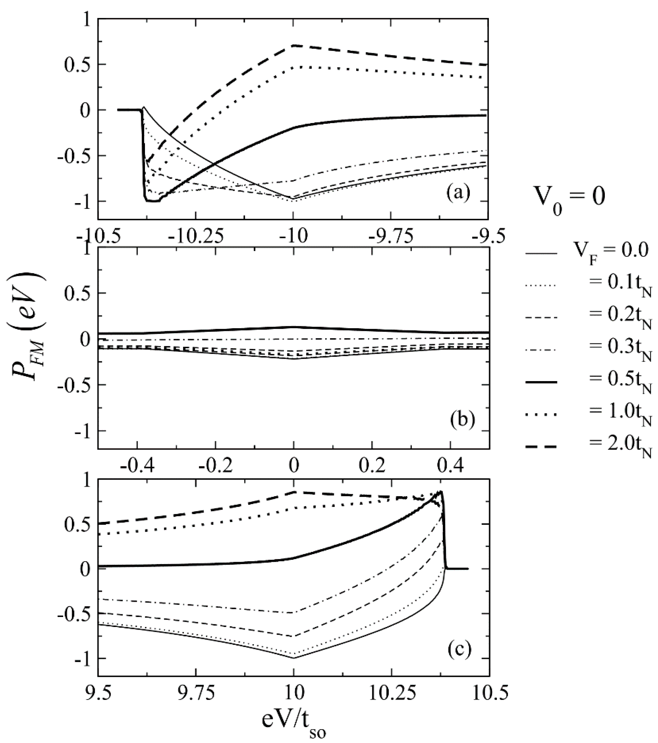
Remarkable effects occur when V F is non-zero. For example, V F significantly influences the spin polarization of current. Increasing V F leads to a rise in spin polarization, as illustrated in Figure 3. The spin-flip scattering potential influences spin transport by controlling whether a particle’s spin passes through or is reflected by the junction barrier. However, the value of spin polarization is suppressed when both V F and V 0 are taken into account. Near the half-filled band, the spin polarization of current remains modest, even when both types of scattering potentials are included. Moreover, when the spin-flip barrier belongs to the tunneling limit ( V F > 0.5 t N ), the spin polarization gains a positive value. This suggests that the barrier potential with a spin-flip scattering may filter the spin current across the heterostructure [40,41].
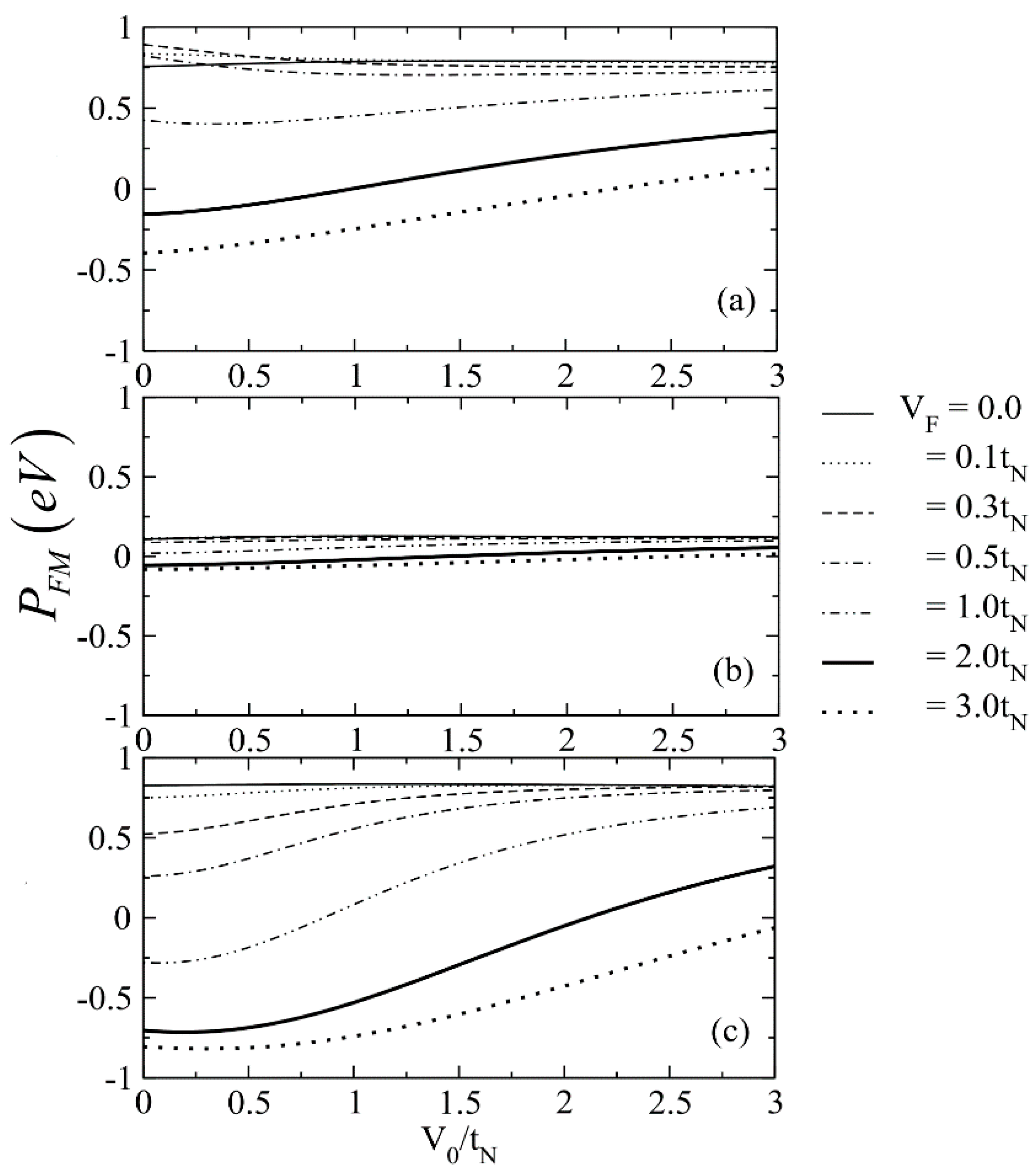
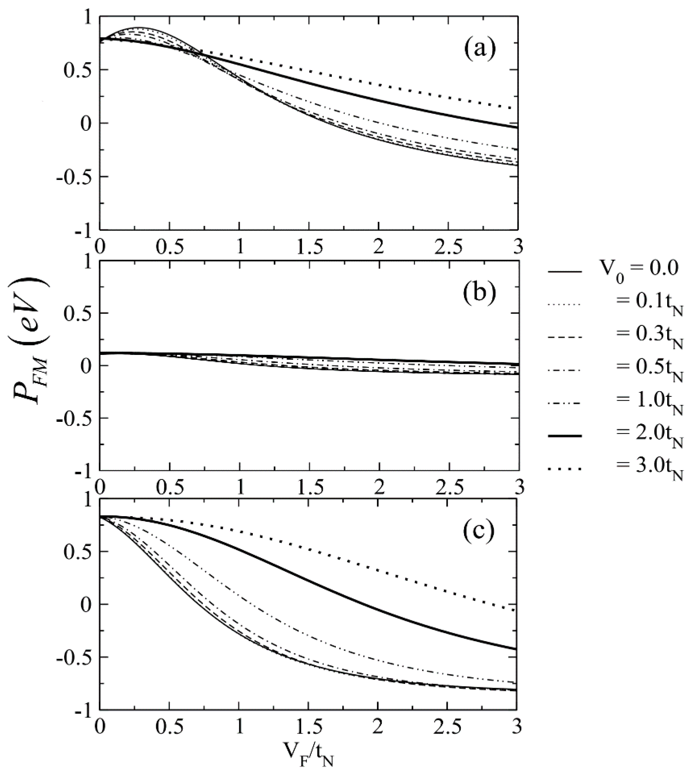
The spin polarization of current as a function of a spin-conserved scattering by varying the spin-flip, is shown in Figure 4, and as a function of non-spin-flip by changing the spin-conserved scattering is shown in Figure 5. Figure 4a,c illustrates that the spin-flip scattering changes the sign of the spin polarization of current from negative to positive for low values of the non-spin-flip. This can be used to screen the direction of the spin transport to a heterostructure [42]. For the region around the middle band (Figure 4b), the spin polarization of current is relatively unaffected by the modulation of both scattering potential barriers.
In Figure 5, again, as in Figure 4, it is observed that for relatively small values of V F , the quantity of the spin polarization of current remains nearly unaffected by increases in V 0 . In contrast, as V F becomes sufficiently large, Figure 4c displays a pronounced sign reversal, transitioning from positive to negative values, as also shows Figure 5.
The numerical results presented in this paper reveal that the spin polarization of current in an FM/SC heterostructure RSOI is highly sensitive to both the applied bias voltage and the nature of the interfacial scattering potential. In particular, the spin polarization is shown to undergo a sign change as the energy approaches the Rashba band crossing point, and that the inclusion of spin-flip scattering at the interface may selectively enhance or suppress spin components, effectively acting as a spin filter.
Interestingly, the numerical predictions of bias-dependent spin polarization inversion due to the interplay of RSOI and spin-dependent interfacial scattering bear qualitative resemblance to recent experimental findings in van der Waals spin valves based on FGeT/MoSe2/FGeT junctions [17] and FGaT/hBN/FGaT junction [14]. This behavior is in agreement with the result obtained that the spin polarization of current changes sign under increasing voltage, controlled by the relative contributions of spin-conserved and spin-flip scattering in the presence of RSOI. The high interfacial spin polarization observed experimentally further supports the assertion made here that asymmetric interfacial scattering and spin–orbit coupling can lead to energy-selective spin filtering.
Furthermore, the MR was observed in van der Waals FGeT spin valves [15,17], where the MR sign changes from negative to positive as barrier thickness decreases. While the crossover behavior of the valves is driven by geometric modulation, specifically the thickness-dependent orbital symmetry filtering, the theoretical model considered captures a similar sign change in spin polarization of current as a function of applied voltage and scattering mechanisms. In particular, this study finds that spin polarization can switch sign near specific Rashba band energies due to selective filtering of spin species, dominated by spin-conserved and spin-flip scattering potentials at the interface.
Altogether, the present study provides a theoretical framework that captures qualitative key features observed in recent experiments, particularly spin polarization change, spin filtering, and bias-dependent spin transport. While the model considered adopts a simplified representation of the interface and band structure, it offers mechanistic insight that could be extended to realistic material systems through incorporation of first-principles band structures and experimentally determined scattering parameters. Future work is to combine the model considered here with density functional theory (DFT)-derived inputs to achieve quantitative predictions tailored to specific vdW–MTJ systems.

4. Conclusions

This study explores the impact of interfacial scattering potentials on the spin polarization of current in a heterostructure of a semiconductor-based Rashba spin–orbit interaction with an empty energy band and a ferromagnetic material, using Equation (13) to analyze different scattering scenarios. Both spin-conserving ( V 0 ) and spin-flip ( V F ) scattering potentials are considered. The findings show that, in the absence of V 0 and V F , spin polarization becomes negative when the applied voltage reaches the Rashba band crossing points, indicating an imbalance of spin-up and spin-down particles. The analysis presented reveals that the non-spin-flip scattering potential plays a crucial role in modulating spin polarization characteristics. Particularly, sufficiently large non-spin-flip scattering barriers can drive a complete inversion of the spin polarization orientation.

Funding

This research was funded by the University Income Fund, Naresuan University, Thailand, grant number R2567C006.

Data Availability Statement

The data are presented in this study.

Acknowledgments

Thanks are given to Kyle V. Lopin for editing the manuscript.

Conflicts of Interest

The author declares no conflicts of interest.

References

  1. Manchon, A.; Koo, H.C.; Nitta, J.; Frolov, S.M.; Duine, R.A. New perspectives for Rashba spin-orbit coupling. Nat. Mater. 2015, 14, 871–882. [Google Scholar] [CrossRef] [PubMed]
  2. Koo, H.C.; Kim, S.B.; Kim, H.; Park, T.E.; Choi, J.W.; Kim, K.-W.; Go, G.; Oh, J.H.; Lee, D.-K.; Park, E.-S.; et al. Rashba effect in functional spintronic devices. Adv. Mater. 2020, 32, 2002117. [Google Scholar] [CrossRef] [PubMed]
  3. Chen, J.; Wu, K.; Hu, W.; Yang, J. Spin–orbit coupling in 2D semiconductors: A theoretical perspective. J. Phys. Chem. Lett. 2021, 12, 12256–12268. [Google Scholar] [CrossRef] [PubMed]
  4. Bercioux, D.; Lucignano, P. Quantum transport in Rashba spin–orbit materials: A review. Rep. Prog. Phys. 2015, 78, 106001. [Google Scholar] [CrossRef] [PubMed]
  5. Bihlmayer, G.; Noël, P.; Vyalikh, D.V.; Chulkov, E.V.; Manchon, A. Rashba-like physics in condensed matter. Nat. Rev Phys. 2022, 4, 642–659. [Google Scholar] [CrossRef]
  6. Shen, C.; Cai, R.; Matos-Abiague, A.; Han, W.; Han, J.E.; Žutić, I. Rashba spin–orbit coupling enhanced magnetoresistance in junctions with one ferromagnet. Phys. Rev. B. 2023, 107, 125306. [Google Scholar] [CrossRef]
  7. Moodera, J.S.; Kinder, L.R.; Wong, T.M.; Meservey, R. Large magnetoresistance at room temperature in ferromagnetic thin film tunnel junctions. Phys. Rev. Lett. 1995, 74, 3273–3276. [Google Scholar] [CrossRef] [PubMed]
  8. Julliere, M. Tunneling between ferromagnetic films. Phys. Lett. A 1975, 54, 225–226. [Google Scholar] [CrossRef]
  9. Yuasa, S.; Nagahama, T.; Fukushima, A.; Suzuki, Y.; Ando, K. Giant room-temperature magnetoresistance in single-crystal Fe/MgO/Fe magnetic tunnel junctions. Nat. Mater. 2004, 3, 868–871. [Google Scholar] [CrossRef] [PubMed]
  10. Zutić, I.; Fabian, J.; Das Sarma, S. Spintronics: Fundamentals and applications. Rev. Mod. Phys. 2004, 76, 323–410. [Google Scholar] [CrossRef]
  11. Zhu, W.; Zhu, Y.; Zhou, T.; Zhang, X.; Lin, H.; Cui, Q.; Yan, F.; Wang, Z.; Deng, Y.; Yang, H.; et al. Large and tunable magnetoresistance in van der Waals ferromagnet/semiconductor junctions. Nat. Commun. 2023, 14, 5371. [Google Scholar] [CrossRef] [PubMed]
  12. Zhu, W.; Lin, H.; Yan, F.; Hu, C.; Wang, Z.; Zhao, L.; Deng, Y.; Kudrynsky, Z.R.; Zhou, T.; Kovalyuk, Z.D.; et al. Large tunneling magnetoresistance in van der Waals ferromagnet/semiconductor heterojunctions. Adv. Mater. 2021, 33, 2104658. [Google Scholar] [CrossRef] [PubMed]
  13. Fei, Z.; Huang, B.; Malinowski, P.; Wang, W.; Song, T.; Sanchez, J.; Yao, W.; Xiao, D.; Zhu, X.; May, A.F.; et al. Two-dimensional itinerant ferromagnetism in atomically thin Fe3GeTe2. Nat. Mater. 2018, 17, 778–782. [Google Scholar] [CrossRef] [PubMed]
  14. Zhang, L.; He, M.; Wang, X.; Zhang, H.; Han, K.; Liu, Y.; Zhang, L.; Cheng, Y.; Pan, J.; Qu, Z.; et al. Bias voltage controlled inversions of tunneling magnetoresistance in van der Waals heterostructures Fe3GaTe2/hBN/Fe3GaTe2. J. Phys. D 2025, 58, 105005. [Google Scholar] [CrossRef]
  15. Zheng, Y.; Ma, X.; Yan, F.; Lin, H.; Zhu, W.; Ji, Y.; Wang, R.; Wang, K. Spin filtering effect in all-van der Waals heterostructures with WSe2 barriers. npj 2D Mater. Appl. 2022, 6, 62. [Google Scholar] [CrossRef]
  16. Zhu, S.; Lin, H.; Zhu, W.; Li, W.; Zhang, J.; Wang, K. Voltage tunable sign inversion of magnetoresistance in van der Waals Fe3GeTe2/MoSe2/Fe3GeTe2 tunnel junctions. Appl. Phys. Lett. 2024, 124, 222401. [Google Scholar] [CrossRef]
  17. Lin, H.; Yan, F.; Hu, C.; Lv, Q.; Zhu, W.; Wang, Z.; Wei, Z.; Chang, K.; Wang, K. Spin-valve effect in Fe3GeTe2/MoS2/Fe3GeTe2 van der Waals heterostructures. ACS Appl. Mater. Interf. 2020, 12, 43921–43926. [Google Scholar] [CrossRef] [PubMed]
  18. Rashba, E. Properties of semiconductors with an extremum loop. 1. Cyclotron and combinational resonance in a magnetic field perpendicular to the plane of the loop. Sov. Phys. Solid State 1960, 2, 1109–1122. [Google Scholar]
  19. Bychkov, Y.A.; Rasbha, E.I. Properties of a 2D electron gas with lifted spectral degeneracy. JETP Lett. 1984, 39, 78–81. Available online: http://jetpletters.ru/ps/1264/article_19121.shtml (accessed on 5 June 2025).
  20. Datta, S.; Das, B. Electronic analog of the electrooptic modulator. Appl. Phys. Lett. 1990, 56, 665–667. [Google Scholar] [CrossRef]
  21. Hall, K.C.; Lau, W.H.; Gündoğdu, K.; Flatté, M.E.; Boggess, T.F. Nonmagnetic semiconductor spin transistor. Appl. Phys. Lett. 2003, 83, 2937–2939. [Google Scholar] [CrossRef]
  22. Xiong, Z.; Wu, D.; Valy, V.Z.; Shi, J. Giant magnetoresistance in organic spin-valves. Nature 2004, 427, 821–824. [Google Scholar] [CrossRef] [PubMed]
  23. Bandyopadhyay, S.; Cahay, M. Electron spin for classical information processing: A brief survey of spin-based logic devices, gates and circuits. Nanotechnology 2009, 20, 412001. [Google Scholar] [CrossRef] [PubMed]
  24. Fert, A.; Jaffrès, H. Conditions for efficient spin injection from a ferromagnetic metal into a semiconductor. Phys. Rev. B. 2001, 64, 184420. [Google Scholar] [CrossRef]
  25. Guinea, F. Spin-flip scattering in magnetic junctions. Phys. Rev. B. 1998, 58, 9212–9216. [Google Scholar] [CrossRef]
  26. Lyu, P.; Xing, D.Y.; Dong, J. Tunneling magnetoresistance in mixed-valence manganite tunnel junctions. Phys. Rev. B. 1998, 58, 54–57. [Google Scholar] [CrossRef]
  27. Inoue, J.; Maekawa, S. Effects of spin-flip and magnon-inelastic scattering on tunnel magnetoresistance. J. Magn. Magn. Mater. 1999, 198-199, 167–169. [Google Scholar] [CrossRef]
  28. Jansen, R.; Moodera, J.S. Magnetoresistance in doped magnetic tunnel junctions: Effect of spin scattering and impurity-assisted transport. Phys. Rev. B. 2000, 61, 9047–9050. [Google Scholar] [CrossRef]
  29. Vedyayev, A.; Bagrets, D.; Bagrets, A.; Dieny, B. Resonant spin-dependent tunneling in spin-valve junctions in the presence of paramagnetic impurities. Phys. Rev. B. 2001, 63, 064429. [Google Scholar] [CrossRef]
  30. Pasanai, K.; Pairor, P. Spin-flip scattering and dimensional effect on transport of charge and spin across metal/ferromagnet material interfaces. Phys. Rev. B. 2011, 84, 224432. [Google Scholar] [CrossRef]
  31. Srisongmuang, B.; Pairor, P.; Berciu, M. Tunneling conductance of a two-dimensional electron gas with Rashba spin-orbit coupling. Phys. Rev. B. 2008, 78, 155317. [Google Scholar] [CrossRef]
  32. Jantayod, A.; Pairor, P. Charge and spin transport across two-dimensional non-centrosymmetric semiconductor/metal interface. Phys. E Low-Dimens. Syst. Nanostruct. 2013, 48, 111–117. [Google Scholar] [CrossRef]
  33. Grundler, D. Oscillatory spin-filtering due to gate control of spin-dependent interface conductance. Phys. Rev. Lett. 2001, 86, 1058–1061. [Google Scholar] [CrossRef] [PubMed]
  34. Hu, C.-M.; Matsuyama, T. Spin injection across a heterojunction: A ballistic picture. Phys. Rev. Lett. 2001, 87, 066803. [Google Scholar] [CrossRef] [PubMed]
  35. Li, H.; Yang, X. Quantum point contact conductance in ferromagnetic semiconductor/superconductor junctions. J. Magn. Magn. Mater. 2011, 323, 2899–2902. [Google Scholar] [CrossRef]
  36. Mireles, F.; Kirczenow, G. Ballistic spin-polarized transport and Rashba spin precession in semiconductor nanowires. Phys. Rev. B 2001, 64, 024426. [Google Scholar] [CrossRef]
  37. Yang, Z.H.; Yang, Y.H.; Wang, J.; Chan, K.S. Spin-orbital coupling effect on Josephson current through a superconductor heterojunction. J. Appl. Phys. 2008, 103, 103905. [Google Scholar] [CrossRef]
  38. Jantayod, A. Tight binding calculation of tunneling conductance of a metal/ferromagnetic junction. Phys. B Condens. Matter 2017, 525, 7–11. [Google Scholar] [CrossRef]
  39. Blonder, G.E.; Tinkham, M.; Klapwijk, T.M. Transition from metallic to tunneling regimes in superconducting microconstrictions: Excess current, charge imbalance, and supercurrent conversion. Phys. Rev. B. 1982, 25, 4515–4532. [Google Scholar] [CrossRef]
  40. Huang, Y.; Polojärvi, V.; Hiura, S.; Höjer, P.; Aho, A.; Isoaho, R.; Hakkarainen, T.; Gunia, M.; Sato, S.; Takayama, J.; et al. Room-temperature electron spin polarization exceeding 90% in an opto-spintronic semiconductor nanostructure via remote spin filtering. Nat. Photon. 2021, 15, 475–482. [Google Scholar] [CrossRef]
  41. Mantsevich, V.N.; Rozhansky, I.V.; Frolov, D.A.; Maslova, N.S.; Averkiev, N.S. Effective spin filtering in correlated semiconductor nanostructures. J. Magn. Magn. Mater. 2023, 58, 171357. [Google Scholar] [CrossRef]
  42. Erekhinsky, M.; Sharoni, A.; Casanova, F.; Schuller, I.K. Surface enhanced spin-flip scattering in lateral spin valves. Appl. Phys. Lett. 2010, 96, 022513. [Google Scholar] [CrossRef]
Figure 1. The square lattices of FM/SM with RSOI (upper) and electron’s energy dispersion in the semiconductor (lower) with RSOI (right) and the ferromagnetic (left). See text for details.
Physics 07 00029 g001
Figure 2. Numerical results of spin polarization of current versus normalized applied voltage, e V , for different values of V 0 when V F = 0 for applied voltage equivalent to the energy near the first crossing point (a), the middle band (b), and the second crossing point (c) of the RSOI band. See text for details.
Physics 07 00029 g002
Figure 3. Numerical results of spin polarization of current versus normalized applied voltage, e V , for different values of V F when V 0 = 0 for applied voltage equivalent to the energy near the first crossing point (a), the middle band (b), and the second crossing point (c) of the RSOI band.
Physics 07 00029 g003
Figure 4. Numerical results of spin polarization of current versus normalized spin-conserved scattering V 0 for different values of V F for applied voltage equivalent to the energy near the first crossing point (a), the middle band (b), and the second crossing point (c) of the RSOI band. See text for details.
Physics 07 00029 g004
Figure 5. Numerical results of the spin polarization of current versus spin-flip scattering V F for different values of V 0 for applied voltage equivalent to the energy near the first crossing point (a), the middle band (b), and the second crossing point (c) of the RSOI band. See text for details.
Physics 07 00029 g005
Disclaimer/Publisher’s Note: The statements, opinions and data contained in all publications are solely those of the individual author(s) and contributor(s) and not of MDPI and/or the editor(s). MDPI and/or the editor(s) disclaim responsibility for any injury to people or property resulting from any ideas, methods, instructions or products referred to in the content.