Quantum Scattering by Multiple Slits—A Lippmann–Schwinger Approach


Abstract
1. Introduction
2. Scattering by a Finite Segment
2.1. Solution for Exterior Region
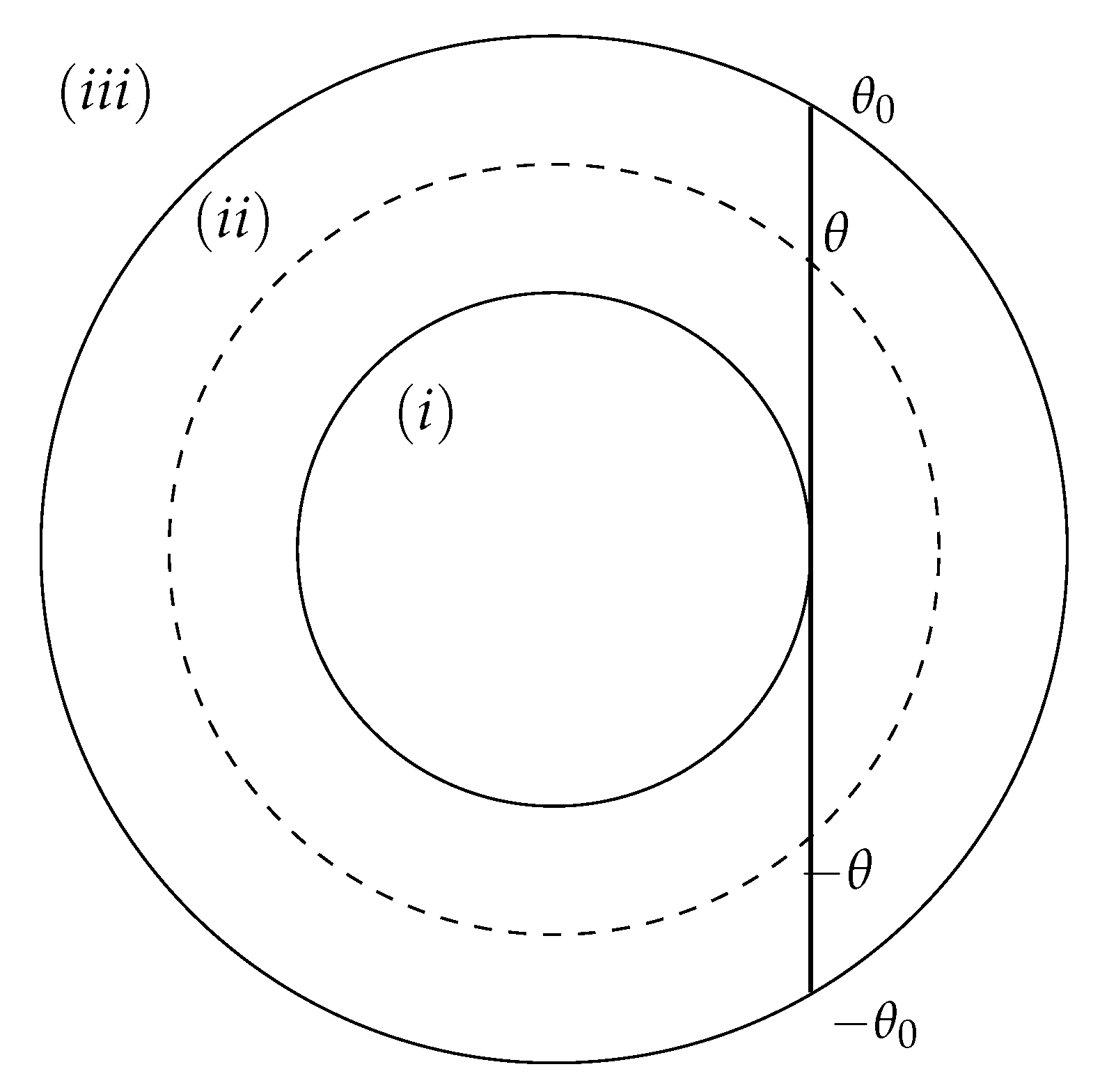
2.2. Solution for Ring Region
2.3. Solution for Interior Region
2.4. Complete Solution
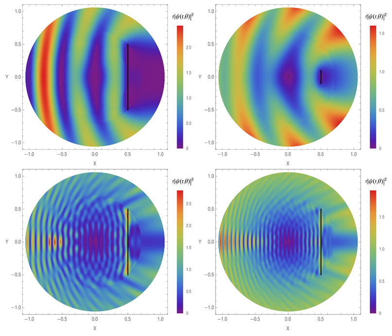
3. Single Slit
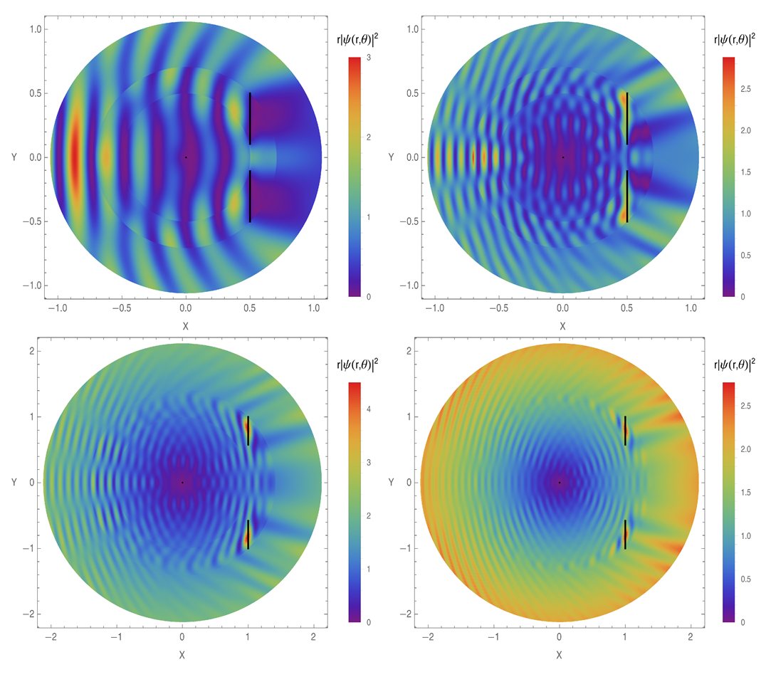
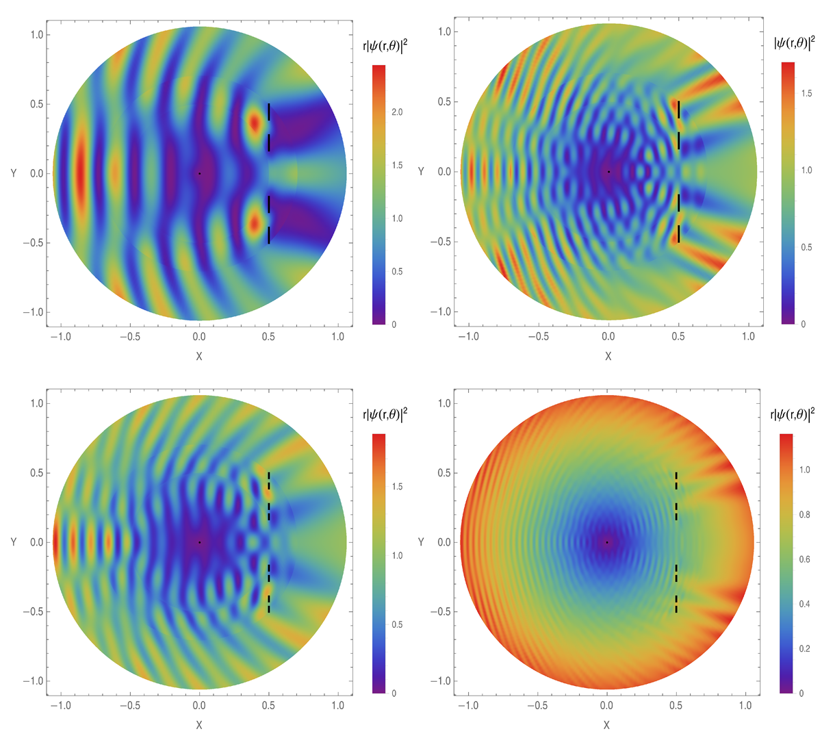
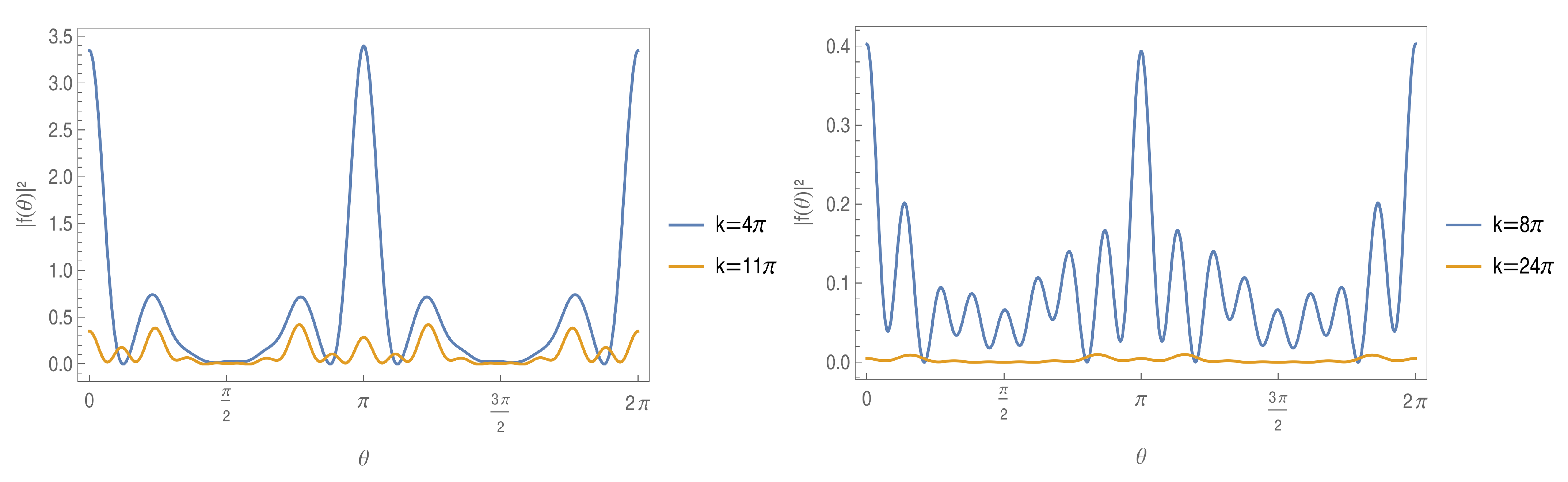
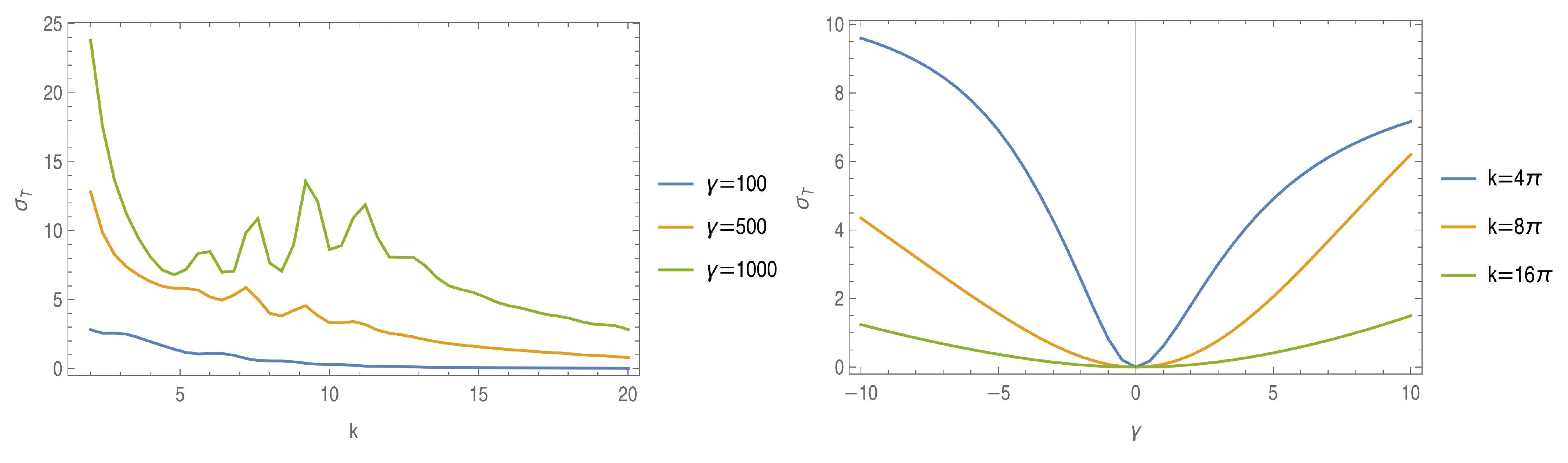
4. Double Slit
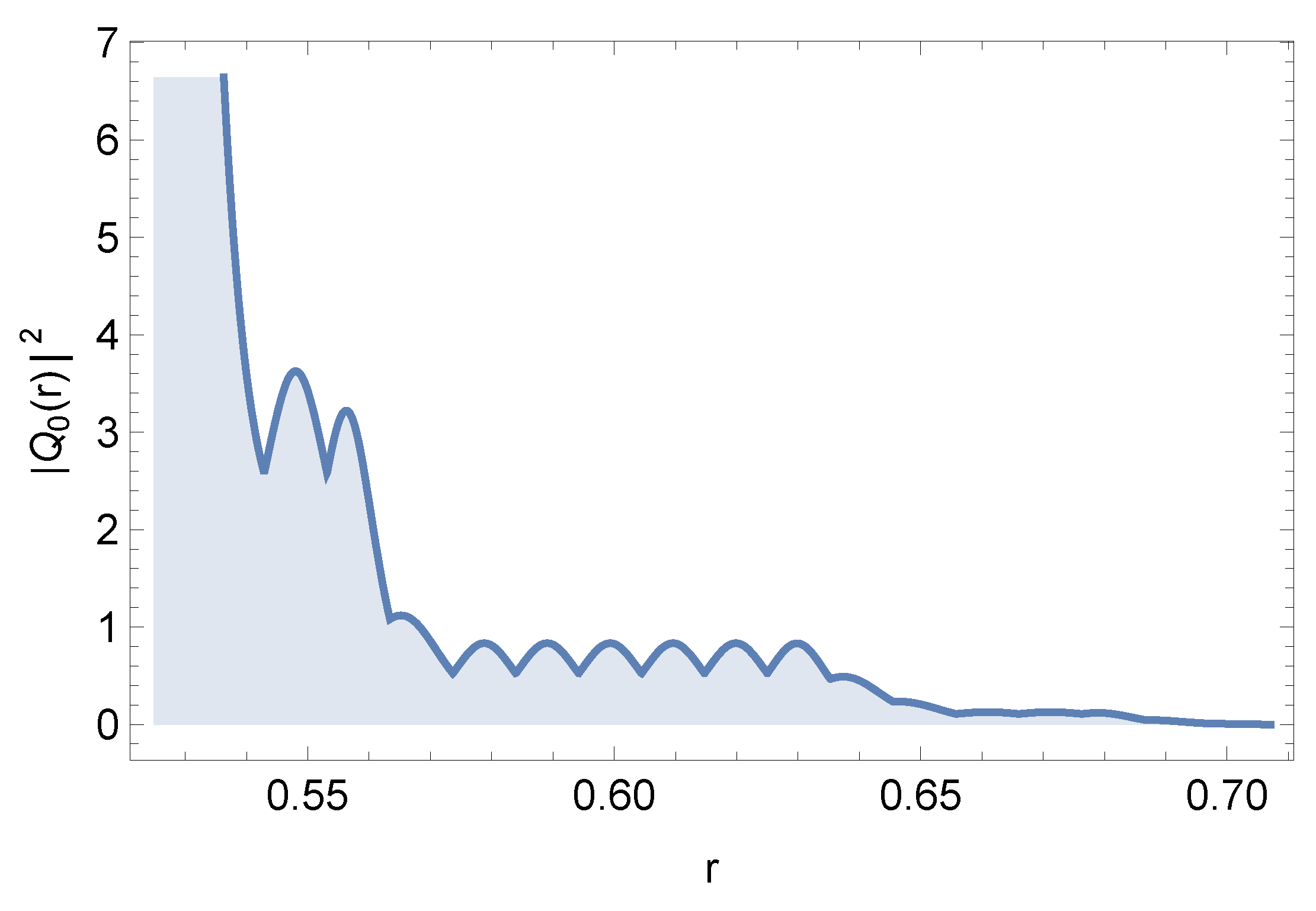
5. Multiple Slits Defined by Cantor Set
6. Conclusions
Author Contributions
Funding
Data Availability Statement
Conflicts of Interest
References
- Belkić, D. Principles of Quantum Scattering Theory; IOP Publishing/Taylot & Francis Group: Oxon, UK, 2004. [Google Scholar] [CrossRef]
- Taylor, J.R. Scattering Theory: The Quantum Theory of Nonrelativistic Collisions; John Wiley & Sons, Inc.: Toronto, ON, Canada, 1972; Available online: https://cdn.preterhuman.net/texts/science_and_technology/physics/quantum_mechanics/ (accessed on 19 May 2025).
- Lippmann, B.A.; Schwinger, J. Variational principles for scattering processes. I. Phys. Rev. 1950, 79, 469–480. [Google Scholar] [CrossRef]
- Ruiz–Biestro, A.; Gutiérrez–Vega, J.C. Solutions of the Lippmann–Schwinger equation for confocal parabolic billiards. Phys. Rev. E 2024, 109, 034203. [Google Scholar] [CrossRef] [PubMed]
- Maioli, A.C.; Schmidt, A.G.M. Exact solution to Lippmann–Schwinger equation for an elliptical billiard. Phys. E Low-Dim. Syst. Nanostruct. 2019, 111, 51–62. [Google Scholar] [CrossRef]
- Maioli, A.C.; Schmidt, A.G.M. Exact solution to Lippmann-Schwinger equation for a circular billiard. J. Math. Phys. 2018, 59, 122102. [Google Scholar] [CrossRef]
- Schmidt, A.G.M.; Maioli, A.C.; Azado, P.C. Exact solution to the Lippmann–Schwinger equation for a spheroidal barrier. J. Quantit. Spectrosc. Radiat. Transf. 2020, 253, 107154. [Google Scholar] [CrossRef]
- Pereira, M.E.; Cunha, P.H.S.; Schmidt, A.G.M. Quantum scattering in a wavy circle. Phys. E Low-Dim. Syst. Nanostruct. 2024, 161, 115965. [Google Scholar] [CrossRef]
- Schmidt, A.G.M.; Pereira, M.E. Quantum refractive index for two- and three-dimensional systems. Ann. Phys. 2023, 452, 169273. [Google Scholar] [CrossRef]
- Vargiamidis, V.; Valassiades, O.; Kyriakos, D.S. Lippmann–Schwinger equation approach to scattering in quantum wires. Phys. Stat. Sol. B Basic Sol. State Phys. 2003, 236, 597–613. [Google Scholar] [CrossRef]
- Sheka, D.D.; Kravchuk, V.P.; Gaididei, Y. Curvature effects in statics and dynamics of low dimensional magnets. J. Phys. A 2015, 48, 125202. [Google Scholar] [CrossRef]
- Nishiguchi, N. Electron scattering by surface vibration in a rectangular quantum wire. Phys. E Low-Dim. Syst. Nanostruct. 2002, 13, 1–10. [Google Scholar] [CrossRef]
- Ono, S.; Shima, H. Low-temperature resistivity anomalies in periodic curved surfaces. Phys. E Low-Dim. Syst. Nanostruct. 2010, 42, 1224–1227. [Google Scholar] [CrossRef]
- Streubel, R.; Fischer, P.; Kronast, F.; Kravchuk, V.P.; Sheka, D.D.; Gaididei, Y.; Schmidt, O.G.; Makarov, D. Magnetism in curved geometries. J. Phys. D 2016, 49, 363001. [Google Scholar] [CrossRef]
- Ortix, C. Quantum mechanics of a spin-orbit coupled electron constrained to a space curve. Phys. Rev. B 2015, 91, 245412. [Google Scholar] [CrossRef]
- Andrade, F.M.; Chumbes, A.R.; Filgueiras, C.; Silva, E.O. Quantum motion of a spinless particle in curved space: A viewpoint of scattering theory. Eur. Phys. Lett. 2019, 128, 10002. [Google Scholar] [CrossRef]
- Crommie, M.F.; Lutz, C.P.; Eigler, D.M.; Heller, E.J. Quantum corrals. Phys. D 1995, 83, 98–108. [Google Scholar] [CrossRef]
- Schmidt, A.G.M.; Pereira, M.E. Analog model for scalar dynamics in a Kerr–Sen background. J. Math. Phys. 2024, 65, 122501. [Google Scholar] [CrossRef]
- Almeida, C.R.; Jacquet, M.J. Analogue gravity and the Hawking effect: Historical perspective and literature review. Eur. Phys. J. H 2023, 48, 15. [Google Scholar] [CrossRef]
- Feynman, R.P.; Leighton, R.B.; Sands, M. The Feynman Lectures on Physics; Basic Books: New York, NY, USA, 2011; Available online: https://www.feynmanlectures.caltech.edu/ (accessed on 19 May 2025).
- da Luz, M.G.E.; Lupu-Sax, A.S.; Heller, E.J. Quantum scattering from arbitrary boundaries. Phys. Rev. E 1997, 56, 2496–2507. [Google Scholar] [CrossRef]
- Kosztin, I.; Schulten, K. Boundary integral method for stationary states of two-dimensional quantum systems. Int. J. Mod. Phys. C 1997, 8, 293–325. [Google Scholar] [CrossRef]
- Goldberger, M.L.; Watson, K.M. Collision Theory; John Wiley & Sons, Inc.: New York, NY, USA, 1964; Available online: https://www.scribd.com/document/76856455/Marvin-L-Goldberger-and-Kenneth-M-Watson-Collision-Theory (accessed on 19 May 2025).
- Cavero-Peláez, I.; Milton, K.A.; Kirsten, K. Local and global Casimir energies for a semitransparent cylindrical shell. J. Phys. A 2007, 40, 3607–3632. [Google Scholar] [CrossRef]
- Gorban, M.J.; Julius, W.D.; Brown, P.M.; Matulevich, J.A.; Radhakrishnan, R.; Cleaver, G.B. First- and second-order forces in the asymmetric dynamical Casimir effect for a single δ − δ′ mirror. Physics 2024, 6, 760–779. [Google Scholar] [CrossRef]
- Oliveira, L.S.; Pereira, M.E.; Balthazar, W.F.; Schmidt, A.G.M.; Huguenin, J.A.O. Experimental study of the solutions of the Lippmann–Schwinger equation for an elliptical billiard with an intense laser beam. Phys. Lett. A 2024, 521, 129738. [Google Scholar] [CrossRef]
- Zanetti, F.M.; Lyra, M.L.; de Moura, F.A.B.F.; da Luz, M.G.E. Resonant scattering states in 2D nanostructured waveguides: A boundary wall approach. J. Phys. B 2009, 42, 025402. [Google Scholar] [CrossRef]
- Zanetti, F.M.; Vicentini, E.; da Luz, M.G.E. Eigenstates and scattering solutions for billiard problems: A boundary wall approach. Ann. Phys. 2008, 323, 1644–1676. [Google Scholar] [CrossRef]
- Azevedo, A.L.; Maioli, A.C.; Teston, F.; Sales, M.R.; Zanetti, F.M.; da Luz, M.G.E. Wave amplitude gain within wedge waveguides through scattering by simple obstacles. Phys. Rev. E 2024, 109, 025303. [Google Scholar] [CrossRef]
- Folland, G.B. Fourier Analysis and Its Applications; Brooks/Cole Publishing Company of Wadsworth, Inc.: Belmont, CA, USA, 1992; Available online: https://dokumen.pub/fourier-analysis-and-its-applications.html (accessed on 19 May 2025).
- Duffy, D.G. Green’s Functions with Applications; A Chapman & Hall Book; CRC Press/Taylor & Francis Group, LLC: New York, NY, USA, 2015. [Google Scholar] [CrossRef]
- Cohl, H.S.; Dang, T.H.; Dunster, T.M. Fundamental solutions and Gegenbauer expansions of Helmholtz operators in Riemannian spaces of constant curvature. Symmetry Itegrab.Geom. Meth. Appl. (SIGMA) 2018, 14, 136. [Google Scholar] [CrossRef]
- Pereira, M.E.; Schmidt, A.G.M. Exact solutions for Lippmann–Schwinger equation for the scattering by hyper-spherical potentials. Few-Body Syst. 2022, 63, 25. [Google Scholar] [CrossRef]
- Byron, F.W., Jr.; Fuller, R.W. Mathematics of Classical and Quantum Physics; Dover Publications, Inc.: New York, NY, USA, 1970; Available online: https://archive.org/details/mathematicsofcla00byro (accessed on 19 May 2025).
- Tricomi, F.G. Integral Equations; Dover Publications, Inc.: New York, NY, USA, 2012; Available online: https://archive.org/details/integralequation0000tric (accessed on 19 May 2025).
- Polyanin, A.D.; Manzhirov, A.V. Handbook of Integral Equations; CRC Press LLC: Boca Raton, FL, USA, 1998. [Google Scholar] [CrossRef]
- Watson, G.N. A Treatise on the Theory of Bessel Functions; Cambridge University Press: Cambridge, UK, 1995; Available online: https://www.scribd.com/doc/294269253/Treatise-on-the-Theory-of-Bessel-Functions (accessed on 19 May 2025).
- Kouri, D.J.; Vijay, A.; Hoffman, D.K. Inverse scattering theory: Renormalization of the Lippmann–Schwinger equation for quantum elastic scattering with spherical symmetry. J. Phys. Chem. A 2003, 107, 7230–7235. [Google Scholar] [CrossRef]
- Lima, E.L. Análise Real. Volume 1: Funčões de Uma Variável; IMPA: Rio de Janeiro, Brazil, 1989. [Google Scholar]
- Cherny, A.Y.; Anitas, E.M.; Kuklin, A.I.; Balasoiu, M.; Osipov, V.A. Scattering from generalized Cantor fractals. J. Appl. Crystallogr. 2010, 43, 790–797. [Google Scholar] [CrossRef]
- Hatano, N. Strong resonance of light in a Cantor set. J. Phys. Soc. Jpn. 2005, 74, 3093–3111. [Google Scholar] [CrossRef]
- Jung, C.; Scholz, H.J. Cantor set structures in the singularities of classical potential scattering. J. Phys. A 1987, 20, 3607–3617. [Google Scholar] [CrossRef]
- Rodrigo, J.A.; Alieva, T.; Calvo, M.L.; Davis, J.A. Diffraction by Cantor fractal zone plates. J. Mod. Optics 2005, 52, 2771–2783. [Google Scholar] [CrossRef]


Disclaimer/Publisher’s Note: The statements, opinions and data contained in all publications are solely those of the individual author(s) and contributor(s) and not of MDPI and/or the editor(s). MDPI and/or the editor(s) disclaim responsibility for any injury to people or property resulting from any ideas, methods, instructions or products referred to in the content. |
© 2025 by the authors. Licensee MDPI, Basel, Switzerland. This article is an open access article distributed under the terms and conditions of the Creative Commons Attribution (CC BY) license (https://creativecommons.org/licenses/by/4.0/).
Share and Cite
Fortiny, R.M.; Pereira, M.E.; Schmidt, A.G.M. Quantum Scattering by Multiple Slits—A Lippmann–Schwinger Approach. Physics 2025, 7, 25. https://doi.org/10.3390/physics7030025
Fortiny RM, Pereira ME, Schmidt AGM. Quantum Scattering by Multiple Slits—A Lippmann–Schwinger Approach. Physics. 2025; 7(3):25. https://doi.org/10.3390/physics7030025
Chicago/Turabian StyleFortiny, Rafael M., Matheus E. Pereira, and Alexandre G. M. Schmidt. 2025. "Quantum Scattering by Multiple Slits—A Lippmann–Schwinger Approach" Physics 7, no. 3: 25. https://doi.org/10.3390/physics7030025
APA StyleFortiny, R. M., Pereira, M. E., & Schmidt, A. G. M. (2025). Quantum Scattering by Multiple Slits—A Lippmann–Schwinger Approach. Physics, 7(3), 25. https://doi.org/10.3390/physics7030025