Article

Design of a Compact Microreactor/Heat-Exchanger for a Distributed Production of Liquid Hydrocarbons from Methanol

1
School of Engineering, University of Warwick, Coventry CV4 7AL, UK
2
School of Chemical Engineering and Chemistry, Eindhoven University of Technology, 5600 MB Eindhoven, The Netherlands
*
Author to whom correspondence should be addressed.
Reactions 2021, 2(4), 427-441; https://doi.org/10.3390/reactions2040027
Submission received: 3 June 2021 / Revised: 15 September 2021 / Accepted: 12 October 2021 / Published: 18 October 2021
(This article belongs to the Special Issue Feature Papers in Reactions in 2021)

Abstract

:
The paper compares conceptual designs of a microstructured reactor/heat-exchanger for the small-scale production of C8+ range hydrocarbons from methanol over H-ZSM-5 catalytic coatings. In these designs, air was used as a cooling fluid in the adjacent cooling channels. The heat transfer characteristics of a single-zone reactor (with channels 500 μm in diameter) and a two-zone reactor (with an additional coolant inlet) have been compared. A single reaction zone was not able to reduce the temperature gradient below 15 K, while a two-zone configuration, with a counter-current fluid flow in the upstream section and co-current flow in the downstream section, demonstrated a near-isothermal behaviour, with a mean temperature of 653 K.

1. Introduction

1.1. Methanol-to-Hydrocarbon Process

The implementation of large-scale infrastructure projects in the Arctic is impossible without a constant supply of fuels and lubricants, including special types of diesel fuels. Therefore, it becomes increasingly important to develop a technology capable of producing these fuels locally, as their transportation from refineries to remote areas substantially increases fuel costs. To achieve this, mobile production units that can be housed and installed in containers are needed. At the same time, many suppliers of natural gas operating in remote areas have significant supply of hydrocarbon feedstock (such as stable natural gas condensate) that cannot be used as commercial fuels without further processing. Natural gas condensate is usually composed of hydrocarbons, such as propane, butane, and pentane. Currently, there is no commercial process to convert gas condensate directly to diesel fuels. However, a steam reforming process can be employed on a small scale [1] to convert the gas condensate to a mixture of hydrogen, CO, and CO2. The syngas produced is then adjusted, sent for methanol synthesis, and then further to the gasoline production step [2].
Commercially, methanol is produced from syngas, which is usually derived from natural gas. In an alternative method, methanol is produced from CO2 over a CuO/ZnO/Al2O3 catalyst [3]. In turn, the processes for converting methanol into liquid hydrocarbons and methanol-to-hydrocarbons (MTH) (including motor fuels) have been developed over the last 50 years and have been implemented in the industry [4]. The MTH process was commercialized in New Zealand by combining a methanol dehydration reactor and a gasoline synthesis reactor. A selectivity of 80% towards C5–C11 products was reported [5,6]. While the technology has been successfully demonstrated, it is not economically viable at the present methanol price level. Currently, a more complex process, gas-to-liquid (GTL) technology, is implemented in the industry to obtain gasoline, diesel fuel, paraffins, and engine oil components [7]. Large plants, among others (Shell and Sasol) that implemented GTL technology operate according to a three-stage reactor scheme: (i) syngas generation by autothermal reforming (ATR), (ii) hydrocarbon synthesis by the Fisher–Tropsch (FT) method, and (iii) hydrocracking of FT synthesis products [8]. The hydrocracking is an energy-intensive process that requires rather high temperatures.
While the chemical industry has not been yet interested in the alternative technologies, mainly due to the lack of economic feasibility, much research is ongoing, and an interesting alternative to the GTL process is a single-step methanol-to-hydrocarbon (MTH) reactor. This process also enables an alternative path for high-octane, gasoline-based products obtained from non-oil resources [9,10,11]. Due to exothermic nature of methanol dehydration and hydrocarbon formation, temperature control in a conventional MTH reactor is a major challenge [4]. Hotspots over 500 K generate an uneven concentration distribution and facilitate irreversible catalyst deactivation; both resulting in an uncontrollable product selectivity [12]. Therefore, the process was initially carried out in two individual reactors [13]. At first, methanol is vaporized and fed into a fixed-bed dimethylether (DME) reactor. In the DME reactor, the methanol is converted to a mixture of methanol, DME, and water. The mixture from the DME reactor has a temperature of 623–643 K, and it is fed to the reactor containing H-ZSM-5 zeolite (ZSM-5 reactor), where about 85% of the reaction heat is released. The rising temperature in the ZSM-5 reactor may be reduced by recycling a large amount of gas. However, this approach increases the operating costs and cannot be applied on a small scale. The final product is separated into three phases: gas, water, and liquid hydrocarbons. A two-stage process was studied by Menges and Kraushaar-Czarnetzki [14]. They performed their experiments in the 673–723 K range, under variations of the methanol concentrations from 10 to 34 vol.%. Tavan and Hosseini proposed a lumped kinetic model for pure methanol feed [15].

1.2. Application of Structured Catalysts and Reactors

In the DME reactor, either γ-alumina or H-ZSM-5 catalysts have been employed [15]. The H-ZSM-5 catalysts tends to show high activity towards hydrocarbon formation if the temperature in the reactor exceeds 623 K. This often results in a rapid catalyst deactivation, due to coke formation. The γ-alumina catalyst has a much higher thermal stability, and it is cheaper. Mollavali et al. [16] also observed that the H-ZSM-5 catalyst in the first reactor leads to better results, in terms of catalytic activity and operating costs. Compared to alumina catalysts, the use of lower temperature over the H-ZSM-5 catalyst favours the thermodynamic equilibrium of the system and higher methanol conversions could be achieved. It can be concluded that the H-ZSM-5 catalyst is preferred for both reaction zones. The activity and selectivity over H-ZSM-5 zeolite further depends on its acidity (the Si/Al ratio), which can be varied by partial ion-exchange with Ca [17] or via post-synthesis treatments [18]. Yet the internal diffusion of bulky molecules is hindered in microporous zeolites; therefore, only active sites located in the channels close to the crystal outer surface are accessible for the reactants. For this reason, thin films of nanosized zeolites [19], zeolite membranes [20], structured zeolite catalysts [21], and zeolite on the inner reactor walls [22,23] attracted much attention, due to improved mass and heat transfer rates. Newly developed zeolite catalysts have significantly improved stability and high activity [24].
With the surface-to-volume ratio an order of magnitude higher, compared to that in conventional reactors, the microstructured reactors improves the control of the reaction conditions, in order to reduce (or even eliminate) temperature hotspots [25]. Small reactor channel dimensions and high thermal conductivity of the reactor framework enable high heat removal rates [26,27]. The short length of the reactors enhances the mass and heat transfer as velocity, temperature, and concentration profiles are still developing [28]. The catalytic dehydration of ethanol was demonstrated in microreactors with a channel width of 0.1 mm [29] and an ethylene selectivity of 99.4%. However, in case of rapid, highly exothermic reactions, hotspots can be observed, even in microreactors [26,30]. A conventional method for improving the temperature uniformity is to combine a reactor with a heat-exchanger in a co-current, counter-current, or cross-flow design. In general, heat integration approaches for process intensification in portable hydrocarbon processing microreactors can be separated into two categories: firstly, the development of ‘all-in-one’ devices capable of integrating several processes operating at different temperatures and heat duties and secondly, design of a modular network of individual microreactors [31,32,33]. In the first approach, insulating barriers (e.g., insulation plates) are introduced between functional layers, such that individual processes are maintained at different operating temperatures [34,35,36]. The development of a combined methane steam reformer/catalytic burner in a co-current reactor/heat-exchanger with a thermal power of 67 W was reported by Ryi et al. [37]. In the next design, they made longer channels and a reduced plate width, as well as the addition of microstructured heat-exchangers to pre-heat the air feed of the combustor and increase the thermal power to 220 W [38]. Grote et al. presented an integrated diesel steam reformer designed for a thermal input of 10 kW of the diesel [39]. In their optimisation study, they investigated parallel flow, counter flow, and cross flow conditions, along with inlet geometry variations for the reformer. A microreactor/heat-exchanger, consisting of two parallel set of channels for methanol combustion and methanol steam reforming, was numerically simulated by Andisheh Tadbir and Akbari [40]. The effects of process parameters on methanol conversion, hydrogen yield, and CO concentration were examined. More recently, a compact heat integrated reactor system of a steam reformer, a water gas shift reactor, and a combustor were designed for stationary hydrogen production from ethanol [33].
The axial temperature gradient in the reaction channels can be controlled with the flow rate and temperature of the coolant. Anzola et al. [41] compared both co- and counter-current configurations for steam reforming of ethanol over a Pd catalyst. Under co-current flow operation, the microreactor showed a better temperature uniformity, with respect to the counter-current scheme, particularly when rather small channel widths were adopted. Recently, several theoretical studies have been performed to explore possible configurations in highly exothermic reactions [42,43]. Rave et al. concluded that the overall heat transfer coefficient in a microreactor can be adjusted by the process flow rate [42]. However, this requires connecting several plates in series, in order to keep the same residence time. They suggested that up to ten plates can be used in one reactor. Additionally, they concluded that elevated heat transfer is needed, mainly in the first seconds of a reaction (due to high inlet concentrations); therefore, the length of each section can be increased towards the downstream section of the reactor. A further improvement can be achieved with a reactant or coolant multi-injection method [44,45]. By injecting cold feed between reactors in direct or reversal flow direction, heat transfer can be improved, and a more uniform temperature distribution is observed in the reactor. The temperature field in the MRHE is mainly defined by the diameter, number of cooling channels, coolant flow rate, heat conductivity of the reactor material, and distance between the reaction and cooling channels [26]. Therefore, a large number of configurations of the plate reactor are possible, and CFD modelling can help to find the optimal configuration, as well as the optimal process conditions (flow rates and inlet temperatures).
This work is a theoretical study of a MTH reaction over an H-ZSM-5 catalytic coating in a micro-channel reactor/heat-exchanger. The MRHE is convectively cooled, by means of air flow through parallel cooling channels. The main goal of this work is to reduce the temperature gradient in the catalytic coating via a systematic optimization of several design parameters. While the whole assembly is designed for a 6 kg per day hydrocarbon production rate, the modelling of a single reactor unit has been performed in this study. The effects of several reactor design parameters and operating conditions were investigated to achieve a near-isothermal behavior. Although the study is based on a single case of MTH reaction, the results can be used to improve the design process of microstructured reactors, in general, as the same approach can be translated to other fast catalytic reactions.

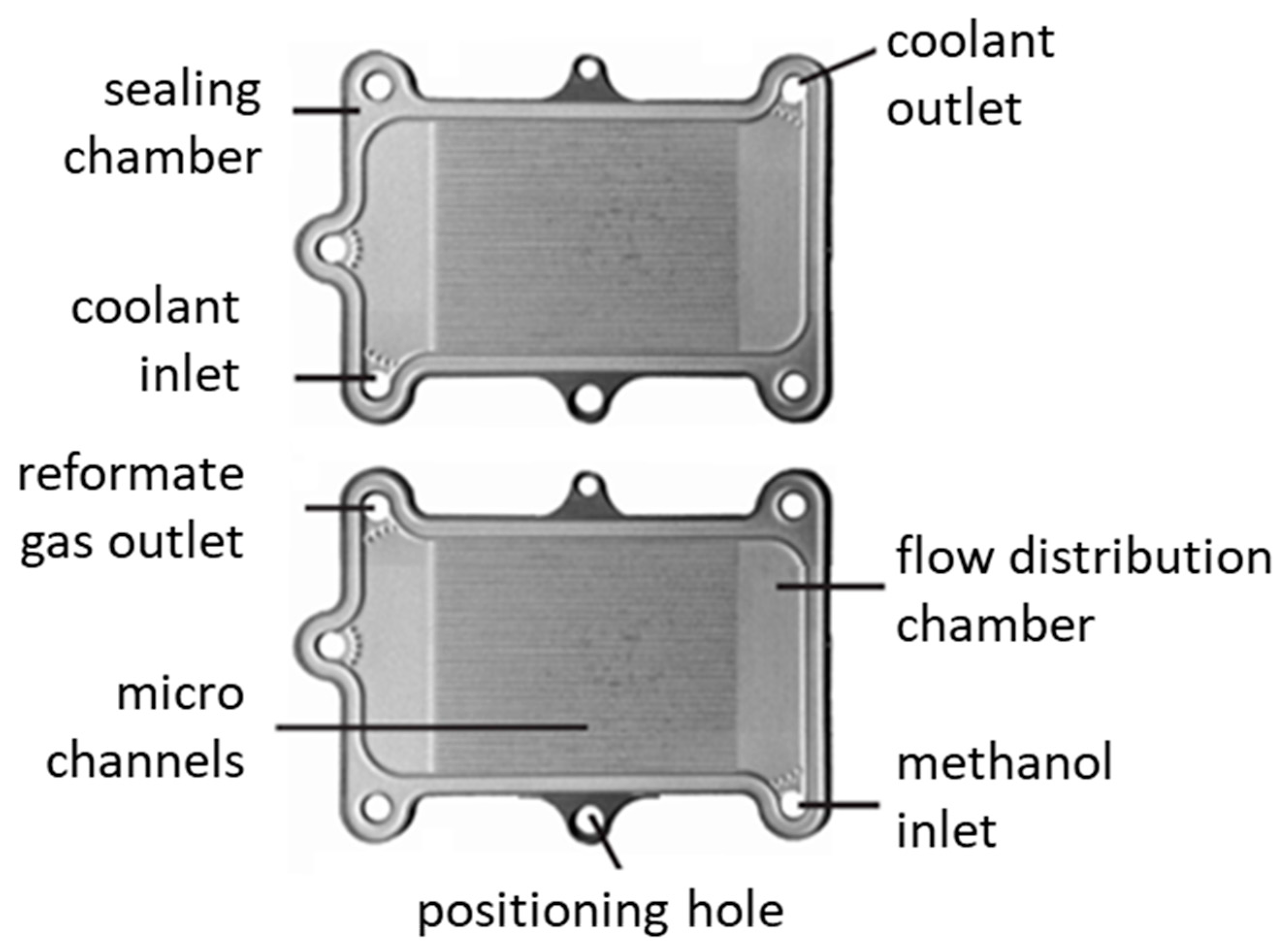
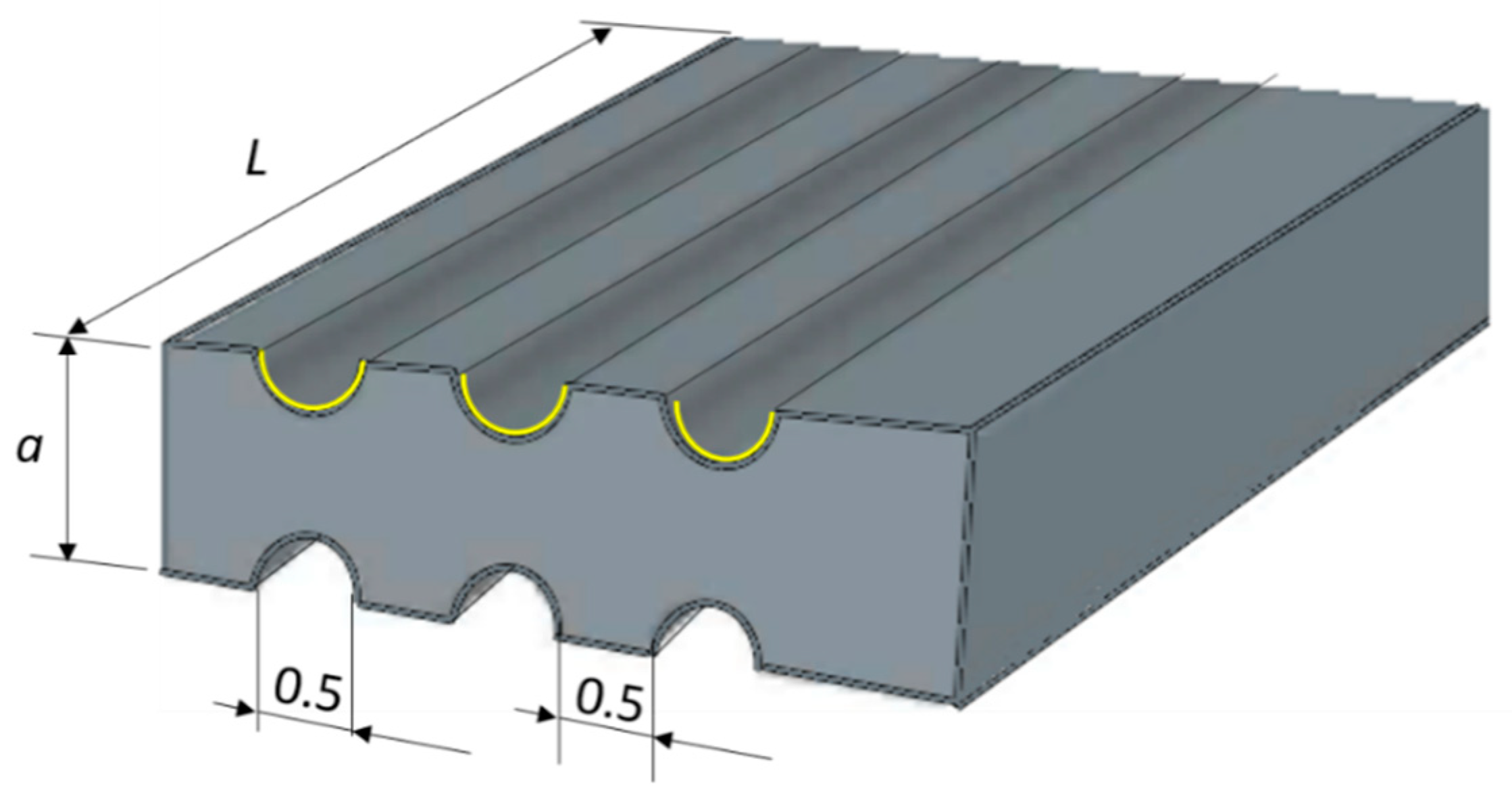
2. Reactor Design and Reaction Kinetics

The microreactor/heat-exchanger (MRHE) device is constructed from individual microstructured plates. The microstructured plates contain an outer groove that serves as a packing chamber, inlet and outlet flow distribution chambers, and a central part containing the actual microchannels (Figure 1). These microstructures were made in the stainless-steel sheets, by means of wet etching. AISI-304 stainless-steel was chosen as the reactor material because of its good compatibility with the catalyst deposition method and ease of micromachining. Holes were drilled in the plates to provide inflow and outflow conduits for the two gas streams and to facilitate positioning of the plates on top of each other.
The MRHE contains two types of plates, which are mirror images of each other, to provide separate flow paths for the reformate gas and the coolant gas (Figure 2). The gases are led to and from the channels through the four holes positioned in the corners, which form conduits when the plates are stacked on top of each other. From the inlets at the bottom side of the plates, the gases are distributed over the plates and, subsequently, over the channels. At the other side of the plate, the gases are collected and exit through the two outlets at the top side. Alternating stacking of the plates creates a counter–current heat-exchanger.
Each plate contains 14 semi-cylindrical reaction channels on one side and 14 semicylindrical cooling channels on the other side. The total length of the reaction channels was fixed at 200 mm, due to fabrication requirements. The diameter of the reaction channels was set at 500 μm. At this diameter, the Damköhler number is below 0.5 at all reaction conditions, which indicates that the mass transfer rate in the reaction channels was always greater than the reaction rate. Other geometrical parameters are listed in Table 1.
The cooling system of the MRHE was designed to provide an average temperature in the reaction channels of 543 K at conditions corresponding to a methanol conversion of 95%. A methanol content of 5 vol.% is allowed in fuels according to the European fuel quality directive [46]. Additionally, the selectivity to C8+ range aliphatic products and stability of the H-ZSM-5 coatings reaches a maximum value at these conditions [24].
The reactions in the MTH process are exothermic and have a theoretical adiabatic temperature rise around 550 K [47]. In the model, methanol was fed into a microchannel under atmosphere pressure at 653 K with a WHSV of 2.4 h−1 [24]. The reactor is assumed to be properly insulated. Laminar flow condition was determined by the low value of Reynolds number of reactant flow of 0.4. Estimation of the pressure drop across the reaction channels gives a difference between the reactor inlet and outlet of below 2%. Uniform flow distribution in all of the channels is considered. Coke formation occurs in the reactor, and the catalyst needs to be regenerated. Fast catalyst deactivation happens after ca 20 h [24]; however, a much shorter period is considered in this model.
Due to the complexity of the MTH reaction mechanism, the development of kinetic models remains difficult. Instead, researchers are focused on lumped models capable of representing the actual kinetics and accosted thermal effect well enough. A simplified reaction scheme used in the model is presented in Equations (1) and (2). The first reaction is the dehydration of methanol. The second reaction is the DME conversion into olefins, mostly C8-C9. The consumption of DME disturbs the equilibrium of the first reaction, which leads to more dehydration of methanol
2 C H 3 O H       r 1   C H 3 O C H 3 + H 2 O , Δ r 1 H 653 K = 7254   J   mol 1  
C H 3 O C H 3           r 2           1 4 C 8 H 16 + H 2 O , Δ r 2 H 653 K = 68,364   J   mol 1  
Equations (1) and (2): Lumped kinetic scheme of the MTH process used in the reactor model.
Reversible second-order equations were used for DME synthesis reaction [48]. For the hydrocarbon synthesis step, our previous data [24] were fitted to obtain the lumped kinetic constant k2. Based on the above considerations, the lumped kinetic model is represented by Equations (3)–(9),
d F M e O H d x = a c r 1
d F D M E d x = a c ( r 1 r 2 )  
where Fi is the molar flow rate and ac is the channel cross sectional area. The reaction rates are defined by:
  r 1 = k 1 ρ ( p M e O H 2 P D M E P W K 1 )   ( mol   m 3   s 1 )  
r 2 = k 2 C D M E   ( mol   m 3   s 1 )
where ρ is the catalyst apparent density, p is the partial pressure, and C is the concentration. The reaction rate constant of methanol dehydration is as follows:
  k 1 = 525.32 exp ( 90589 R T )   ( mol   kg 1   s 1   bar 2 )
The equilibrium constant for the first reaction is as follows:
ln ( K 1 ) = 4019 T + 3.707 ln ( T ) 2.783 × 10 3 T + 3.8 × 10 7 T 2 6.561 × 10 4 T 3 26.64
The reaction rate constant for the second reaction is as follows:
k 2 = exp ( 3.71 8841 R T )   ( s 1 )

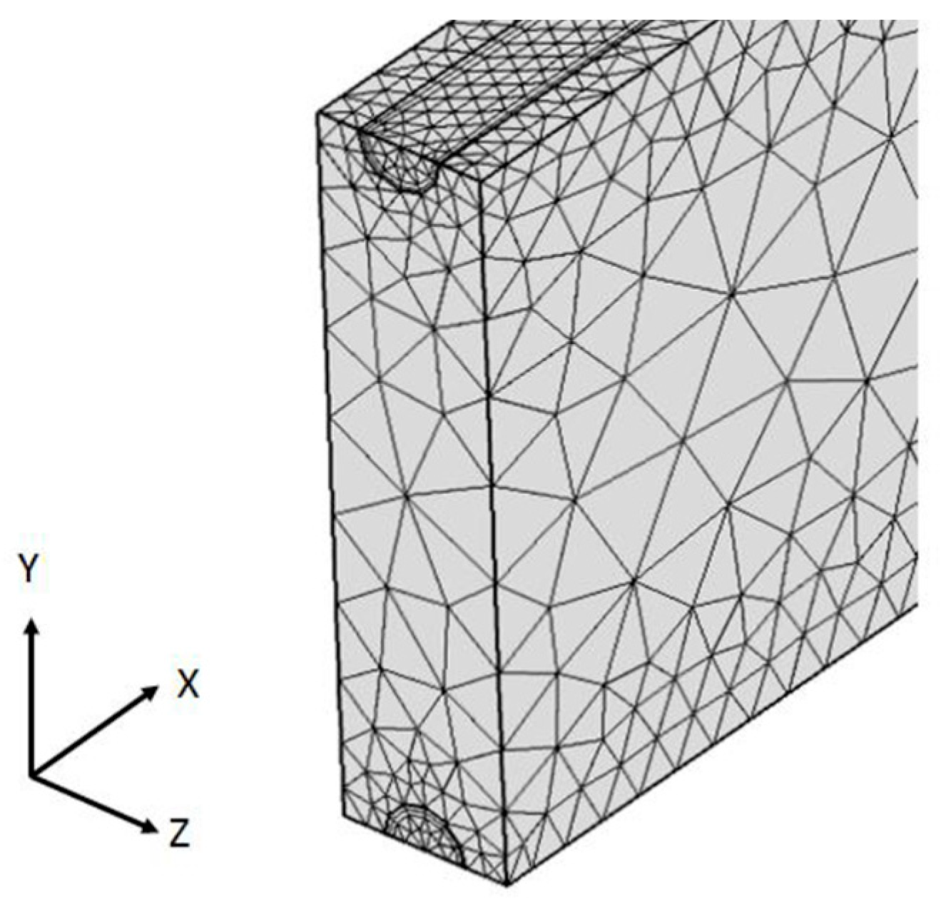
Heat Transfer Modelling

The volumetric heat generation rate in the ZSM-5 coatings was obtained from the reaction enthalpy:
Q = Δ r 1 H × r 1 Δ r 2 H × r 2
where Δ r i H is the enthalpy of reaction i at the reaction temperature.
Initially, a one-dimensional heat transfer model was developed to describe the temperature profile in the MRHE. The model calculates the temperature profiles of the reformate gas (r), the coolant gas (c), and the metal framework (m). For conventional heat-exchangers, the metal walls are not included in the model, as axial heat conduction in the walls can be neglected. However, for the MRHE axial, conduction is an important factor determining the overall performance [25,49]. The radial temperature profile in the metal can be neglected, as the distance between the reformate and coolant channels is rather small and the thermal conductivity of stainless-steel is two orders of magnitude larger than that of the gases.
A uniform flow distribution between all microchannels was assumed. An equal flow distribution can be achieved using special design of the inlet flow chamber, as presented in our previous work [50]. Plug flow was assumed for both gases, and axial dispersion was neglected. In fact, radial diffusion diminishes the spreading effect of the parabolic velocity profile, while the axial diffusion increases the dispersion. Therefore, there exists a range, where the microreactor behaves similar to a fixed bed reactor. For the case presented in this paper, this is given by the following relation: 3 < Pe < 80 [51]. The left end of the equation defines a criterion for neglecting axial dispersion. The right end defines a criterion for neglecting radial concentration variations. The range of Peclet numbers implemented in this study is within the above range; therefore, the axial dispersion introduced by the laminar flow profile can be neglected. The temperature profile of the gases is then determined by convective heat transport and heat exchange with the metal walls. When the axial coordinate is made dimensionless ( x ^ ) with the length of the MRHE, the following equations for the temperatures of reformate (Tr) and coolant (Tc) gas can be written:
m ˙ r C p , r d T r d x ^ = h r A r ( T r T m )  
( ± ) m ˙ c C p , c d T c d x ^ = h c A c ( T m T c )  
where hi are respective gas – solid heat transfer coefficients, and Ai are the respective surface areas of microchannels. The term m ˙ C p represents the heat transport capacity (mass flow rate, m ˙ × heat capacity, and Cp) of fluids. The signs (+) and (−) in Equation (11) correspond to the co-current and counter-current configuration of the coolant flow.
For conventional heat exchangers, the axial conduction in the walls is not modelled, as it can usually be neglected. However, for micro heat exchangers, axial conduction is an important factor determining the heat exchanger efficiency. The equation for the temperature of the metal part between the channels (Tm) includes axial heat conduction term, heat exchange with the two gases, the heat loss to the environment, and the heat production in the coating, due to catalytic reaction (Q), to give:
λ A m L d 2 T m d x ^ 2 = h r A r ( T r T m ) h c A c ( T m T c ) h e x A e x ( T m T ) + Q  
with λm the conductivity of the stainless-steel, Am the metal cross sectional area, T the temperature of the environment (298 K), and L the section length. The convective heat transfer coefficient to the environment (hex) of 2.5 W m−2 K−1 was based on the external surface of the device without insulation (Aex), which was derived from the experimental cooling curve of a similar reactor, following the approach described in [36].

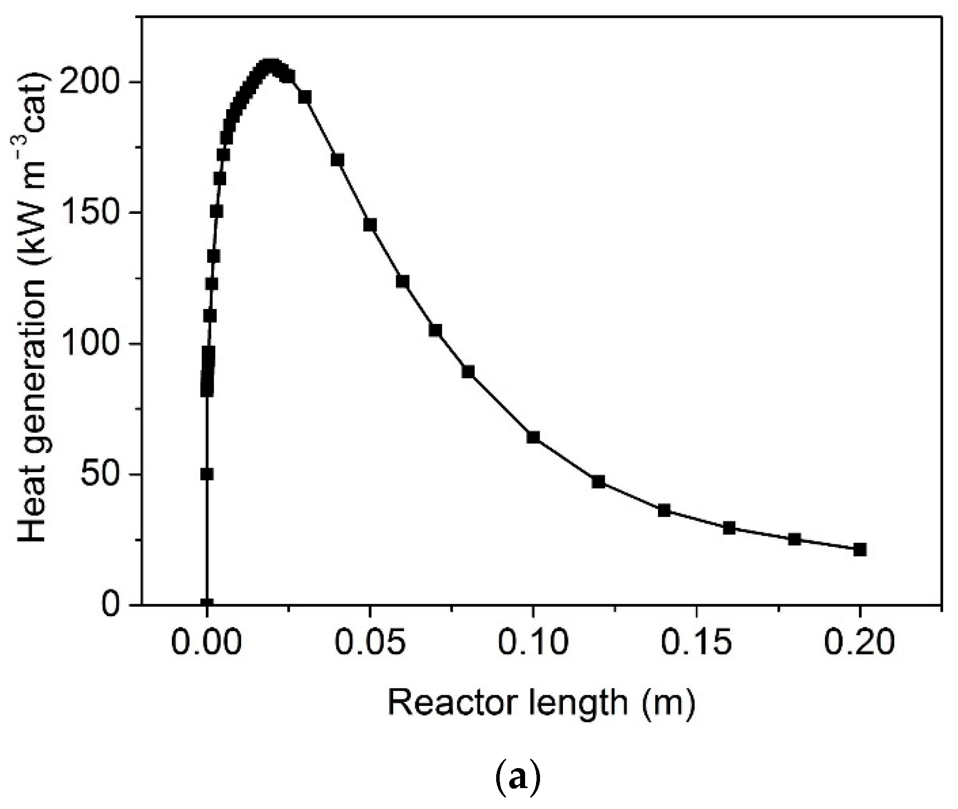
3. Results and Discussion

Effect of Flow Mode

Figure 3 compares the counter-current and co-current flow modes at an optimised coolant flow rate, which provides the minimum temperature non-uniformity in the catalyst layer for both cases. In order to evaluate the temperature profiles at the catalyst position along the reactor, the temperature non-uniformity parameter (δ) was introduced, which is the relative mean-square deviation from the average catalyst temperature (Equation (14)):
δ ( % ) = 1 T ¯ 1 N 1 j 1 N ( T ¯ T j ) 2 × 100 ,
where T ¯ is the average catalyst temperature, T j is the catalyst temperature at position j along the axial reactor coordinate, and N is the total number of positions taken in the optimisation (100). This approach is similar to that applied in our previous study [26].
The counter-current mode could not eliminate the temperature hot spot near the reaction channel inlet, which led to a high temperature gradient of more than 400 K. The temperature profile in the co-current mode showed a rather low temperature gradient of 5 K, at a distance between 0.04 and 0.2 m from the inlet. However, there is still a rather large temperature gradient of more than 50 K in the first 40 mm from the inlet. This indicates that cooling is excessive near the inlet but sufficient to compensate heat generation in the downstream section of the channel.
These data are in line with the methanol concentration profile and the related heat generation curve. At the isothermal operation at 653 K (shown as dashed line in Figure 3), half of the reaction heat is released in the area of 0–40 mm and the other half is spread out through the remaining 160 mm length (Figure 4a). The respective concentration profiles are shown in Figure 4b.
Therefore, it was concluded that a single-zone configuration is not capable of reducing the temperature non-uniformity below 50 K. To reduce the axial temperature gradient, the reactor should be split up in two parts, with an additional coolant inlet between them. Several two-zone configurations (with a different length of the first and second zones) were simulated, keeping the total channel length equal to 200 mm. In this analysis, it was assumed that the coolant flow was split up equally between the first and second reaction zones and the coolant inlet temperature was the same for both reaction zones. This limits the number of variables, and, at the same time, such a configuration would facilitate process control in the MRHE.
The geometrical position for the additional coolant inlet was studied by 3D simulations via the construction of a separate grid for each geometry. In these designs, the volume elements next to the reaction channel walls were assigned as catalytic film with a heat conductivity of the H-ZSM-5 zeolite coating. The areas produced by intersecting the planes through the centers of the microchannels were defined as planes of symmetry. At the channel walls, a non-slip boundary condition was applied, where the velocity was zero. The outlet pressure in both channels was set to equal 1 bar.
Prior to the parametric study, the dependence of the numerical solution on computational mesh density was examined. Three levels of mesh density (coarse, normal, and fine) were studied. In all three meshing schemes, the relative density of the meshing elements followed the order: zeolite coating domain > reaction channel domain = cooling channel domain > reactor wall domain (Figure 5). The difference in temperature profiles, between the normal and fine mush, was below 1 K. That was considered good enough for the purpose of the present design.
The maximum temperature and the temperature gradient decreased when the length of first reaction zone was reduced from 0.050 to 0.025 m (Figure 6). At the same time, the mean temperature in the second reaction zone only slightly increased. A length of 0.030 m corresponds to the minimum temperature non-uniformity over the entire reactor. The heat generation in the first section and in the second section became equal (Figure 4a). Therefore, a two-zone reactor with a channel length of 30 mm (first section) and 170 mm (second section) was selected for subsequent design optimization.
The cooling system of the MRHE was designed to provide an average temperature of the whole unit at 653 K, at conditions corresponding to an adiabatic temperature rise of 550 K. At this temperature, the selectivity to the desired products reaches a maximum at a WHSV of 2.4 h−1.
The counter-current flow direction in the first section provides a minimum temperature gradient of 14 K, at a coolant flow rate of 1310 cm3 min−1 (corresponding to an inlet coolant velocity of 0.09 m s−1 and an inlet coolant temperature of 498 K). An average heat transfer coefficient in the cooling channels was estimated to be 420 W m−2 K−1, using an approximation of a constant wall temperature and laminar flow conditions (Nu = 3.66). A very high heat transfer rate provides very fast heating of the air flow to the temperature of the solid wall in the initial 2 mm section of the cooling channel. Over the largest part of the section length, all three temperatures (Tr, Tm, and Tc) differ by less than 1 K (Figure 7). This is an intrinsic feature of small microchannels providing excellent temperature control in the reaction zone, simply by a proper choice of coolant inlet temperature. However, to reduce the temperature gradient even further, the thermal conductivity of the reactor material should be increased; therefore, more conductive materials, such as nickel or aluminium, should be used for its manufacturing. This part of the optimization was beyond the scope of the present paper.
The coolant flow direction in the second reaction section influences the temperature non-uniformity in it (Figure 8). As the temperature profiles in the reaction channels, cooling channels, and inside the catalyst are virtually the same, only the catalyst temperature profiles will be presented in the subsequent discussion. The co-current flow mode provides a lower temperature gradient of 2 K, while a temperature gradient of 5 K is observed in the counter-current flow mode.
The effect of the reactor plate thickness was also investigated (Figure 9). The larger thickness provides a larger cross-section for conduction heat transfer in the axial direction, which reduces the temperature non-uniformity parameter (Figure 9). However, it also increases the size of the microreactor and, therefore, its external surface area and the heat losses to the environment. The start-up time also increases, due to larger thermal inertia. It can be seen that the slope of the curve decreases as the plate thickness increases above 1.5 mm. Therefore, a thickness of 1.5 mm was selected in the final design. This configuration provides a start-up time of about 90 s, when hot air is used initially to bring the reactor to its operating temperature.
The optimised parameters of the MRHE and inlet flow conditions are listed in Table 2. The total volume of a single reactor unit is 1.01 cm3. It is capable of converting 14.1 g of methanol per hour. Further increases in the production rate can be achieved by numbering up of the single unit using multiscale networks [49].
In this way, a reactor with a total volume of 1 L will be able to produce about 6 kg of hydrocarbon fuels per hour. A prototype container, which includes the MTH reactor, was designed, based on the proposed reactor configuration, to accommodate several reactors. According to the consecutive process steps, the miniplant is split up into three modules: the steam reforming, methanol synthesis, and gasoline synthesis modules [52]. The modular design allows an easier transportation and an independent basic testing of the functionality of the three process steps. Each of the modules was installed in a separately exhausted compartment. The life-cycle assessment results revealed that the newly proposed processes have a clear advantage over the conventional process in some categories, particularly the global warming potential and primary energy demand [2].
Converting natural gas condensate to gasoline on an industrial scale paves the way for a feasible method of manufacturing. With the further development the entire process, it can more easily be up-scaled with decentralised production. We are planning to develop the plant further, with the goal of producing up to 500 L/day of synthetic gasoline. The larger the plant size, the more profitable the plant would be, and cheaper the final fuel. This compact plant can be replicated in different plants producing gasoline, in order to achieve on-spec bulk production of liquid hydrocarbons in remote geographical areas.

4. Conclusions

A microstructured device was designed for the conversion of methanol to C8 hydrocarbons, consisting of two sections of reactors/heat-exchangers, connected in series. Each section has multiple sets of parallel microchannels (reaction channel and cooling channels), which were integrated in a single stack of microstructured plates. In this reactor, a temperature gradient across the H-ZSM-5 catalyst was below 15 K, corresponding to an adiabatic temperature rise of 550 K. It has been shown that a throughput of 6 kg h−1 of liquid hydrocarbons is possible in a reactor with a total volume of 1 L, operated at a mean temperature of 353 K.

Author Contributions

G.H. performed modelling work, interpretation of results, and he prepared an initial draft of the paper; N.C. performed day-to-day management of the project; E.V.R. performed review and editing, funding acquisition, and project administration. All authors have read and agreed to the published version of the manuscript.

Funding

This research was funded by the European Commission, in the scope of the Seventh Framework Programme, BIOGO project (Grant Number: 604296); https://www.biogo.eu, accessed on 10 October 2021.

Data Availability Statement

All data needed to support the conclusions in the paper are present in the paper. Additional data related to this paper may be requested from the authors.

Conflicts of Interest

The authors declare no conflict of interest.

References

  1. Barnoon, P.; Toghraie, D.; Mehmandoust, B.; Fazilati, M.A.; Eftekhari, S.A. Comprehensive study on hydrogen production via propane steam reforming inside a reactor. Energy Rep. 2021, 7, 929–941. [Google Scholar] [CrossRef]
  2. Sundaram, S.; Kolb, G.; Hessel, V.; Wang, Q. Energy-efficient routes for the production of gasoline from biogas and pyrolysis oil—Process design and life-cycle assessment. Ind. Eng. Chem. Res. 2017, 56, 3373–3387. [Google Scholar] [CrossRef] [PubMed] [Green Version]
  3. Jadhav, S.G.; Vaidya, P.D.; Bhanage, B.M.; Joshi, J.B. Catalytic carbon dioxide hydrogenation to methanol: A review of recent studies. Chem. Eng. Res. Des. 2014, 92, 2557–2567. [Google Scholar] [CrossRef]
  4. Chang, C.D.; Silvestri, A.J. The conversion of methanol and other O-compounds to hydrocarbons over zeolite catalysts. J. Catal. 1977, 47, 249–259. [Google Scholar] [CrossRef]
  5. Yurchak, S. Development of mobil’s fixed-bed Methanul-To-Gasoline (MTG) process. In Studies in Surface Science and Catalysis; Bibby, D.M., Chang, C.D., Howe, R.F., Yurchak, S., Eds.; Elsevier: Amsterdam, The Netherlands, 1988; Volume 36, pp. 251–272. ISBN 0167-2991. [Google Scholar]
  6. Chang, C.D. The New Zealand Gas- to-Gasoline plant: An engineering tour de force. Catal. Today 1992, 13, 103–111. [Google Scholar] [CrossRef]
  7. Khodakov, A.Y.; Chu, W.; Fongarland, P. Advances in the development of novel cobalt Fischer-Tropsch catalysts for synthesis of long-chain hydrocarbons and clean fuels. Chem. Rev. 2007, 107, 1692–1744. [Google Scholar] [CrossRef]
  8. De Kok, P.J.; Overtoom, R.R.M. Pearl GTL; Elsevier B.V.: Amsterdam, The Netherlands, 2012. [Google Scholar]
  9. Stöcker, M. Methanol-to-hydrocarbons: Catalytic materials and their behavior. Microporous Mesoporous Mater. 1999, 29, 3–48. [Google Scholar] [CrossRef]
  10. Cui, Z.; Liu, Q.; Ma, Z.; Bian, S.; Song, W. Direct observation of olefin homologations on zeolite ZSM-22 and its implications to methanol to olefin conversion. J. Catal. 2008, 258, 83–86. [Google Scholar] [CrossRef]
  11. Qi, L.; Wei, Y.; Xu, L.; Liu, Z. Reaction behaviors and kinetics during induction period of methanol conversion on HZSM-5 zeolite. ACS Catal. 2015, 5, 3973–3982. [Google Scholar] [CrossRef]
  12. Schmidt, F.; Hoffmann, C.; Giordanino, F.; Bordiga, S.; Simon, P.; Carrillo-Cabrera, W.; Kaskel, S. Coke location in microporous and hierarchical ZSM-5 and the impact on the MTH reaction. J. Catal. 2013, 307, 238–245. [Google Scholar] [CrossRef]
  13. Blauwhoff, P.M.M.; Gosselink, J.W.; Kieffer, E.P.; Sie, S.T.; Stork, W.H.J. Zeolites as catalysts in industrial processes. In Catalysis and Zeolites: Fundamentals and Applications; Weitkamp, J., Puppe, L., Eds.; Springer: Berlin/Heidelberg, Germany, 1999; pp. 437–538. ISBN 978-3-662-03764-5. [Google Scholar]
  14. Menges, M.; Kraushaar-Czarnetzki, B. Kinetics of methanol to olefins over AlPO 4-bound ZSM-5 extrudates in a two-stage unit with dimethyl ether pre-reactor. Microporous Mesoporous Mater. 2012, 164, 172–181. [Google Scholar] [CrossRef]
  15. Tavan, Y.; Hosseini, S.H. From laboratory experiments to simulation studies of methanol dehydration to produce dimethyl ether—Part I: Reaction kinetic study. Chem. Eng. Process. 2013, 73, 144–150. [Google Scholar] [CrossRef]
  16. Mollavali, M.; Yaripour, F.; Atashi, H.; Sahebdelfar, S. Intrinsic kinetics study of dimethyl ether synthesis from methanol on γ-Al2O3 catalysts. Ind. Eng. Chem. Res. 2008, 47, 3265–3273. [Google Scholar] [CrossRef]
  17. Heriyanto, H.; Muraza, O.; Nasser, G.A.; Sanhoob, M.A.; Bakare, I.A.; Rochmadi, B.; Budiman, A. Development of New Kinetic models for methanol to hydrocarbons over a Ca-ZSM-5 Catalyst. Energy Fuels 2020, 34, 6245–6260. [Google Scholar] [CrossRef]
  18. Ma, Q.; Fu, T.; Li, H.; Cui, L.; Li, Z. Insight into the selection of the post-treatment strategy for ZSM-5 zeolites for the improvement of catalytic stability in the conversion of methanol to hydrocarbons. Ind. Eng. Chem. Res. 2020, 59, 11125–11138. [Google Scholar] [CrossRef]
  19. Fu, T.; Chang, J.; Shao, J.; Li, Z. Fabrication of a nano-sized ZSM-5 zeolite with intercrystalline mesopores for conversion of methanol to gasoline. J. Energy Chem. 2017, 26, 139–146. [Google Scholar] [CrossRef] [Green Version]
  20. Masuda, T.; Asanuma, T.; Shouji, M.; Mukai, S.R.; Kawase, M.; Hashimoto, K. Methanol to olefins using ZSM-5 zeolite catalyst membrane reactor. Chem. Eng. Sci. 2003, 58, 649–656. [Google Scholar] [CrossRef]
  21. Omojola, T.; Cherkasov, N.; Rebrov, E.V.; Lukyanov, D.B.; Perera, S.P. Zeolite minilith: A unique structured catalyst for the methanol to gasoline process. Chem. Eng. Process.-Process. Intensif. 2018, 131, 137–143. [Google Scholar] [CrossRef] [Green Version]
  22. Rebrov, E.V. Sol-gel synthesis of zeolite coatings and their application in catalytic microstructured reactors. Catal. Ind. 2009, 1, 322–347. [Google Scholar] [CrossRef]
  23. Rebrov, E.; Hu, G. Novel Zeolite Catalysts for Methanol to Hydrocarbon Transformation; Elsevier Inc.: Amsterdam, The Netherlands, 2018; ISBN 9780128148082. [Google Scholar]
  24. Doluda, V.Y.; Stepacheva, A.A.; Lakina, N.V.; Oleg, V.; Molchanov, V.P.; Demidenko, G.N.; Valentina, G.; Panfilov, V.I.; Sulman, M.G.; Sulman, E.M. Comparison of methanol to gasoline conversion in one-step, two-step, and cascade mode in the presence of H-ZSM-5 zeolite. Int. J. Sustain. Energy 2017, 37, 970–977. [Google Scholar] [CrossRef]
  25. Rebrov, E.; de Croon, M.H.J.; Schouten, J. Design of a microstructured reactor with integrated heat-exchanger for optimum performance of a highly exothermic reaction. Catal. Today 2001, 69, 183–192. [Google Scholar] [CrossRef]
  26. Rebrov, E.V.; Duinkerke, S.A.; de Croon, M.H.J.M.; Schouten, J.C. Optimization of heat transfer characteristics, flow distribution, and reaction processing for a microstructured reactor/heat-exchanger for optimal performance in platinum catalyzed ammonia oxidation. Chem. Eng. J. 2003, 93, 201–216. [Google Scholar] [CrossRef]
  27. Schouten, J.C.; Rebrov, E.V.; de Croon, M.H.J.M. Miniaturization of heterogeneous catalytic reactors: Prospects for new developments in catalysis and process engineering. Chimia 2002, 56, 627–635. [Google Scholar] [CrossRef]
  28. Cybulski, A.; Moulijn, J.A. Monoliths in heterogeneous catalysis. Catal. Rev. 1994, 36, 179–270. [Google Scholar] [CrossRef]
  29. Chen, G.; Li, S.; Jiao, F.; Yuan, Q. Catalytic dehydration of bioethanol to ethylene over TiO2/γ-Al2O3 catalysts in microchannel reactors. Catal. Today 2007, 125, 111–119. [Google Scholar] [CrossRef]
  30. Karim, A.M.; Federici, J.A.; Vlachos, D.G. Portable power production from methanol in an integrated thermoeletric/microreactor system. J. Power Sources 2008, 179, 113–120. [Google Scholar] [CrossRef]
  31. Tonkovich, A.L.Y.; Yang, B.; Perry, S.T.; Fitzgerald, S.P.; Wang, Y. From seconds to milliseconds to microseconds through tailored microchannel reactor design of a steam methane reformer. Catal. Today 2007, 120, 21–29. [Google Scholar] [CrossRef]
  32. Kolb, G. Review: Microstructured reactors for distributed and renewable production of fuels and electrical energy. Chem. Eng. Process. Process. Intensif. 2013, 65, 1–44. [Google Scholar] [CrossRef]
  33. Khaodee, W.; Jiwanuruk, T.; Ountaksinkul, K.; Charojrochkul, S.; Charoensuk, J.; Wongsakulphasatch, S.; Assabumrungrat, S. Compact heat integrated reactor system of steam reformer, shift reactor and combustor for hydrogen production from ethanol. Processes 2020, 8, 708. [Google Scholar] [CrossRef]
  34. Shah, K.; Besser, R.S. Key issues in the microchemical systems-based methanol fuel processor: Energy density, thermal integration, and heat loss mechanisms. J. Power Sources 2007, 166, 177–193. [Google Scholar] [CrossRef]
  35. Shah, K.; Besser, R.S. Understanding thermal integration issues and heat loss pathways in a planar microscale fuel processor: Demonstration of an integrated silicon microreactor-based methanol steam reformer. Chem. Eng. J. 2008, 135, 46–56. [Google Scholar] [CrossRef]
  36. Delsman, E.R.; de Croon, M.H.J.M.; Kramer, G.J.; Cobden, P.D.; Hofmann, C.; Cominos, V.; Schouten, J.C. Experiments and modelling of an integrated preferential oxidation-heat exchanger microdevice. Chem. Eng. J. 2004, 101, 123–131. [Google Scholar] [CrossRef]
  37. Ryi, S.K.; Park, J.S.; Choi, S.H.; Cho, S.H.; Kim, S.H. Novel micro fuel processor for PEMFCs with heat generation by catalytic combustion. Chem. Eng. J. 2005, 113, 47–53. [Google Scholar] [CrossRef]
  38. Ryi, S.K.; Park, J.S.; Cho, S.H.; Kim, S.H. Fast start-up of microchannel fuel processor integrated with an igniter for hydrogen combustion. J. Power Sources 2006, 161, 1234–1240. [Google Scholar] [CrossRef]
  39. Grote, M.; Maximini, M.; Yang, Z.; Engelhardt, P.; Köhne, H.; Lucka, K.; Brenner, M. Experimental and computational investigations of a compact steam reformer for fuel oil and diesel fuel. J. Power Sources 2011, 196, 9027–9035. [Google Scholar] [CrossRef]
  40. Andisheh Tadbir, M.; Akbari, M.H. Integrated methanol reforming and oxidation in wash-coated microreactors: A three-dimensional simulation. Int. J. Hydrogen Energy 2012, 37, 2287–2297. [Google Scholar] [CrossRef]
  41. Anzola, A.M.; Bruschi, Y.M.; López, E.; Schbib, N.S.; Pedernera, M.N.; Borio, D.O. Heat supply and hydrogen yield in an ethanol microreformer. Ind. Eng. Chem. Res. 2011, 50, 2698–2705. [Google Scholar] [CrossRef]
  42. Rave, A.; Kuwertz, R.; Fieg, G.; Heck, J. Modeling and experimental investigation of the spatial heat transfer in a plate reactor with meandering millichannels. Chem. Eng. Process.-Process. Intensif. 2020, 150, 107860. [Google Scholar] [CrossRef]
  43. Belzunce, P.S.; Cadús, L.E.; Rodríguez, M.L. Cross-flow plate reactor for ethanol steam reforming: A theoretical study. Chem. Eng. Process.-Process. Intensif. 2021, 164, 108383. [Google Scholar] [CrossRef]
  44. Dubrovskiy, A.R.; Rebrov, E.V.; Kuznetsov, S.A.; Schouten, J.C. A microstructured reactor/heat-exchanger for the water-gas shift reaction operated in the 533-673 K range. Catal. Today 2009, 147, 198–203. [Google Scholar] [CrossRef]
  45. Roberge, D.M.; Bieler, N.; Mathier, M.; Eyholzer, M.; Zimmermann, B.; Barthe, P.; Guermeur, C.; Lobet, O.; Moreno, M.; Woehl, P. Development of an industrial multi-injection microreactor for fast and exothermic reactions—Part II. Chem. Eng. Technol. 2008, 31, 1155–1161. [Google Scholar] [CrossRef]
  46. Board, N.; Format, E.; Isbn, H.; Pacific, A.; Press, B. The Complete Book on Biomass Based Products (Biochemicals, Biofuels, Activated Carbon), 2015th ed.; NIIR: Delhi, India, 2008; ISBN 9788178331584. [Google Scholar]
  47. Keil, F.J. Methanol-to-hydrocarbons: Process technology. Microporous Mesoporous Mater. 1999, 29, 49–66. [Google Scholar] [CrossRef]
  48. Tavan, Y.; Hasanvandian, R. Two practical equations for methanol dehydration reaction over HZSM-5 catalyst—Part I: Second order rate equation. Fuel 2015, 142, 208–214. [Google Scholar] [CrossRef]
  49. Rebrov, E.V.; Schouten, J.C.; de Croon, M.H.J.M. Single-phase fluid flow distribution and heat transfer in microstructured reactors. Chem. Eng. Sci. 2011, 66, 1374–1393. [Google Scholar] [CrossRef] [Green Version]
  50. Rebrov, E.V.; Ismagilov, I.Z.; Ekatpure, R.P.; De Croon, M.H.J.M.; Schouten, J.C. Header design for flow equalization in microstructured reactors. AIChE J. 2007, 53. [Google Scholar] [CrossRef]
  51. Kockmann, N. Heat transfer and micro heat exchangers. In Transport Phenomena in Micro Process Engineering; Springer: Berlin/Heidelberg, Germany, 2007; pp. 129–162. [Google Scholar]
  52. Newton, H.; Wang, Q.; Sundaram, S.; Van Veen, A.; Kiesewalter, S.; Kolb, G. BIOGO: Contributing to the transformation of the petrochemical industry through advances in nanocatalysts and reactor design. Green Process. Synth. 2015, 4, 433–435. [Google Scholar] [CrossRef]
Figure 1. A top-view of the microstructured reactor/heat-exchanger plate geometry for counter-current operation; stacking of the two plate types creates a unit cell of the heat exchanger. For co-current configuration, the positions of the coolant inlet and outlet ports are inverted.
Reactions 02 00027 g001
Figure 2. Schematic view of a periodic unit of the microchannel reactor/heat exchanger showing 3 out of 14 parallel semicylindrical microchannels. The yellow color represents the H-ZSM-5 coating in the reaction channels.
Reactions 02 00027 g002
Figure 3. Optimised temperature profiles in the MRHE at counter-current (1) and co-current (2) operation. Reactant flow rate: 2.71 × 10⁻² m s−1. Coolant flow rate: 0.18 m s−1. Reactant inlet temperature: 473 K. Coolant inlet temperature: 498 K. Plate thickness, a = 1.5 mm.
Reactions 02 00027 g003
Figure 4. (a) Heat generation profile and (b) concentration profiles of the reactants and reaction products along the reactor length. Initial concentration of methanol: 18.7 mol × m−3, WHSV: 2.4 h−1; catalyst temperature: 653 K; pressure: 1 bar.
Reactions 02 00027 g004aReactions 02 00027 g004b
Figure 5. Meshing scheme of a single periodic unit of the MRHE.
Reactions 02 00027 g005
Figure 6. Temperature profiles in the catalyst, as a function of the position of the additional coolant inlet (L1). First section: counter-current flow. Second section: co-current flow. The insert: temperature non-uniformity parameter, as a function of the coolant inlet position. Coolant temperature: 498 K. Coolant velocity in each section: 9.0 × 10⁻² m s−1. Plate thickness, a = 1.5 mm.
Reactions 02 00027 g006
Figure 7. Temperature profiles in the reaction channel, in the catalyst, and in the cooling channels in the first section of the MRHE. Methanol inlet on the left, coolant inlet on the right. Reactant velocity: 2.71 × 10⁻² m s−1. Coolant velocity: 9.0 × 10⁻² m s−1. Reactant inlet temperature: 473 K. Coolant inlet temperature: 498 K. Plate thickness: a = 1.5 mm.
Reactions 02 00027 g007
Figure 8. Temperature profiles in the catalyst, as a function of the flow configuration in the second reaction section of the MRHE. First section: counter-current flow. Second section: 1—co-current flow, 2—counter-current flow. Reactant velocity: 2.71 × 10⁻² m s−1. Coolant velocity in each section: 9.0 × 10⁻² m s−1. Reactant inlet temperature: 473 K. Coolant inlet temperature: 498 K. Distance a = 1.5 mm.
Reactions 02 00027 g008
Figure 9. The temperature non-uniformity in the upstream section of the MRHE as a function of plate thickness. First section: counter-current flow. Second section co-current flow. Reactant inlet temperature: 473 K. Reactant flow rate: 2.71 × 10⁻² m s−1. Catalyst layer thickness: 10 μm. Coolant velocity in each section: 9.0 × 10⁻² m s−1. Coolant inlet temperature: 498 K.
Reactions 02 00027 g009
Table 1. Geometrical parameters of microreactor heat-exchanger.
ParameterValue
Channel length0.20 m
Channel diameter0.50 mm
Channels per plate14
Fin width0.50 mm
Plate thickness0.50–3.00 mm
Number of plates176 (+2 cover plates)
Total number of channels (reactant size)1232
Thickness of the ZSM-5 coating0.010 mm
Table 2. Parameters of the microreactor/heat-exchanger geometry and inlet conditions.
Microreactor/Heat-Exchanger Parameters
Reactor length (mm)200 (+4 mm for additional inlet chamber)
Reactor width (mm)16
Reactor height (mm)264
Reactor volume (cm3)1.01
Methanol throughput (g h−1)14.1
Parameters of a single plate aReaction channelsCooling
channels
Section 1Section 2
Channel diameter (mm)0.500.500.50
Thickness of ZSM-5 coating (μm)10
Inlet gas velocity (m s−1)2.71 × 10−29.0 × 1029.0 × 10−2
Re number (-)410700700
Flow heat quality (W K−1)3.48 × 10−67.1 × 10−57.1 × 10⁻⁵
Inlet gas temperature (K)473498498
Outlet gas temperature (K)652658652
Flow mode Counter-currentCo-current
Inlet gas flow rate (cm3 min−1 STP) b39013101310
a The parameters for a single metal plate with semi-cylindrical channels from each side. b The values for the entire MRHE.
Publisher’s Note: MDPI stays neutral with regard to jurisdictional claims in published maps and institutional affiliations.

