
Article

Intelligent Load Frequency Control Strategy for Multi-Microgrids with Vehicle-to-Grid Considering Charging Diversity and Extreme Weather

1
Department of Electrical and Electronic Engineering, Faculty of Engineering, The Hong Kong Polytechnic University, Kowloon, Hong Kong, China
2
Research Institute for Smart Energy, The Hong Kong Polytechnic University, Kowloon, Hong Kong, China
3
Policy Research Centre for Innovation and Technology, The Hong Kong Polytechnic University, Kowloon, Hong Kong, China
4
International Centre of Urban Energy Nexus, The Hong Kong Polytechnic University, Kowloon, Hong Kong, China
*
Author to whom correspondence should be addressed.
Smart Cities 2026, 9(5), 88; https://doi.org/10.3390/smartcities9050088
Submission received: 4 April 2026 / Revised: 9 May 2026 / Accepted: 19 May 2026 / Published: 21 May 2026

Highlights

What are the main findings?
  • A multi-microgrid frequency control framework in a smart city is developed by integrating heterogeneous charging infrastructure and user-aware V2G flexibility.
  • An enhanced MA-SAC controller adapts frequency regulation actions to weather-induced variations in EV availability and charging flexibility.
What are the implications of the main findings?
  • The proposed strategy improves frequency stability of urban multi-microgrids under renewable uncertainty while preserving travel requirements of EV users.
  • The framework enables weather-adaptive coordination between transportation electrification and distributed energy systems in future smart-city microgrid operations.

Abstract

With the rapid electrification of urban transportation and increasing penetration of renewable energy, maintaining frequency stability in smart-city multi-microgrids (MMG) systems increasingly depends on coordinated vehicle-to-grid (V2G) flexibility. However, existing load frequency control strategies typically treat electric vehicles (EVs) as homogeneous resources and overlook the impacts of charging-infrastructure diversity, user mobility constraints, and extreme weather conditions on regulation availability. To address these challenges, this study proposes a weather-adaptive intelligent load frequency control strategy for smart-city MMG considering heterogeneous charging stations and energy requirements of EV users. Fast and slow charging infrastructures are modeled separately to reflect their distinct regulation characteristics, while time-varying charging and discharging margins are derived from travel demand, parking duration, and state-of-charge preferences and further adjusted under extreme weather scenarios. Based on these dynamic constraints, an enhanced multi-agent soft actor–critic (MA-SAC) controller coordinates micro gas turbines and charging stations for distributed frequency regulation. Simulations demonstrate MA-SAC outperforms PID, Fuzzy, and MA-DDPG methods, achieving a 98.51% frequency excellent rate normally and 91.47% during extreme weather. It reduces maximum deviations by up to 80% versus PID, while preserving user travel requirements. The proposed framework provides a practical pathway for integrating electrified mobility into resilient smart-city MMG frequency regulation.

1. Introduction

1.1. Background

With the rapid development of smart-city infrastructures, urban energy systems are undergoing a profound transition driven by distributed renewable generation and transportation electrification. In this context, multi-microgrid architectures have emerged as an effective framework for coordinating geographically distributed energy resources, facilitating localized power balancing, reducing transmission losses, and accommodating the high penetration of distributed renewables [1,2]. However, the intermittency of renewables exacerbates the low inertia characteristic of microgrids, which may lead to frequency deviations when the systems suffer from load disturbances [3,4]. As a product of smart-city electrified mobility systems, through vehicle-to-grid (V2G) technology, electric vehicles (EVs) can provide sub-second power response [5,6]. Empirical evidence from pioneering regions further validates this trend. For instance, in California, USA, utilities like Pacific Gas and Electric (PG&E) have deployed vehicle-to-microgrid pilots utilizing electric school buses and commercial fleets to provide community resiliency, with state projections indicating that bidirectional EVs could add over 100 GWh of capacity to the grid by 2027. Similarly, Shenzhen, China, has integrated over 760 V2G-enabled charging stations. Flagship sites such as the Hongqiao Park demonstration station feature single-gun megawatt-level V2G chargers and achieve total station discharge capacities exceeding 2.7 megawatts (MW). During a recent city-wide V2G test in Shenzhen, over 17,000 EVs were aggregated to supply power back to the grid, proving that large-scale EV coordination can reliably offer megawatt-level regulation capacity. Consequently, EVs are increasingly serving as a flexible mobile energy storage resource that improves microgrid frequency stability [7,8,9]. Nevertheless, traditional load frequency control (LFC) strategies often treat EVs as homogeneous aggregations, overlooking the diversity of charging infrastructure and the heterogeneity of user time–energy demands, which are further distorted by extreme weather conditions, leading to insufficient adaptability of the strategies. Therefore, there is an urgent need to develop an intelligent LFC strategy that takes the factors above into account, which constitutes the core starting point of this study.

1.2. Related Work

Concerning the issue of EVs participating in LFC, extensive discussions have been conducted in the academic community. This paper identifies several challenges that need to be addressed:
Firstly, in terms of control strategy and algorithms, existing research contributes to balancing regulation accuracy and response speed. For example, Raju and Srikanth introduce a multi-stage PID controller to minimize the microgrid frequency fluctuation during different conditions in [10], whereas this study concentrates on islanded microgrids, which may face the inadequate adaptiveness in a MMG system with frequent dynamic interactions. To improve frequency damping performance of MMG systems, a single-input interval type-2 fuzzy logic controller (SI-IT2-FLCs) is designed, and its effectiveness is validated by a hardware-in-the-loop (HIL) simulator [11]. Khokhar et al. [12] present a tilt integral derivative (TID) controller, which achieves LFC of an EV-enhanced MMG system. Although these methods achieve effective LFC in specific scenarios, the overall architecture still focuses on a traditional centralized framework, which lacks the capability to conduct fine-grained characterization of the heterogeneity of highly dynamic V2G resources and various charging patterns. Minchala et al. [13] propose a V2G frequency regulation scheme based on model predictive control (MPC). Its predictive capability is leveraged to address system time delay. However, MPC is highly dependent on accurate physical linear models. When facing MMG systems that feature high nonlinearity and topological dynamic variations, their errors often lead to a substantial degradation of control performance. With the development of artificial intelligence, Fan [14] adopts multi-agent deep reinforcement learning (MA-DDPG) to handle cooperative frequency regulation issues, which remarkably improves the self-adaptivity of the strategy. These pure data-driven methods ignore the integration with physical model constraints, which are sometimes deficient in balancing the economic conflicts between the frequency stability of the microgrid and the requirements of EV users, leading to the control strategy tending to fall into a local optimum under conditions of extreme load fluctuations [15].
Meanwhile, in terms of the EV modeling depth, existing research generally tends to oversimplify. In [5,16,17], the group of EVs within a region is abstracted as a homogeneous energy storage unit. Although Shrivastava et al. [18] analyze five scenarios with varying EV fleet sizes from 20 to 100, they did not consider the fundamental distinction between fast charging stations (FCSs) and slow charging stations (SCSs): FCSs are typically connected to high-voltage-level modes, which are capable of millisecond-level power bursts, yet prone to causing localized voltage sag [19,20]. Though SCSs respond more slowly, their huge energy-storage ability is the key to smooth long-term frequency variations [21]. If the heterogeneity of charging equipment is neglected, the frequency-control instructions may not incorporate the physical constraints of each node during the distribution process, reducing the actual regulation effectiveness.
Furthermore, existing studies fail to adequately characterize the stochasticity of EV users’ behavior. Even though [22,23] try to introduce SOC as a control variation to constrain the operation of V2G, their modeling logic still adheres to a grid-centric approach, which lacks consideration for subjective preferences and behavioral restrictions of EV users [24,25]. Dong and Guo [25] indicate that the core limitation in the V2G model lies in neglecting the self-determination of EV holders. They are rational decision-makers rather than a passive load node. In reality, when participating in V2G, the willingness of EV users is deeply influenced by the inherent permissible departure time interval and their range anxiety [26,27,28]. For instance, commuting users with fixed work schedules have strict time constraints on parking duration, while long-distance travelers tend to maintain higher safety SOC to cope with unexpected travel demands. Overlooking the time and power demand of EV users may lead to unpredictability of V2G participating rate in real-world scenarios, resulting in control failure when large-scale unpredictable departures happen [29].
Finally, the impact of extreme weather on the coupled dynamic system of transportation and electricity needs further exploration. Existing research is mostly based on mild conditions. However, they have not managed to quantify the multi-dimensional distortion effects under extreme environments [25,30]. Yang et al. [31] put forward an agent-based V2G response model for extreme event restoration, however, the proposed model did not combined weather factors with a dynamic frequency control strategy. Wang et al. [32] establish a blizzard-induced grid failure model, whereas no consideration is given to the frequency regulation potential of EVs and the impact of traffic flow on V2G resources accessibility.

1.3. Contributions

In light of the aforementioned challenges, existing studies often struggle with infrastructure diversity, user demand heterogeneity, and operational robustness under extreme environmental factors. This not only weakens the feasibility of V2G control methods but also limits their stability under extreme conditions. To address these gaps, this paper proposes an adaptive LFC strategy for a MMG with V2G considering charging diversity and extreme weather conditions. The main contributions are as follows:
(1) A dynamic MMG frequency model that captures the heterogeneous physical characteristics of charging infrastructure is established. Rather than aggregating EV flexibility into a single homogeneous resource, this work explicitly differentiates between fast charging stations (FCSs) and slow charging stations (SCSs). By detailing their distinct frequency regulation responses, power adjustment boundaries, and energy conversion efficiencies, the proposed model achieves an accurate mapping between frequency control signals and the actual execution capabilities of diverse charging stations.
(2) A behavior-driven method for quantifying the realistic regulation boundaries of V2G strategies is developed. To balance EV travel requirements and grid energy security, this method incorporates departure state-of-charge (SOC) targets, parking durations, and charging mode selections to categorize EV participation into three modes: mandatory charging, flexible charging, and bidirectional participation. By ensuring the fulfillment of individual travel needs, this approach translates stochastic user behaviors into real-time, continuous power regulation boundaries, effectively resolving the discontinuous control issues prevalent in existing aggregated models.
(3) An adaptive MA-SAC controller tailored for frequency regulation under extreme weather conditions is designed. Advancing beyond our previous work on MA-DDPG and general microgrid resilience, the proposed controller introduces dynamic adjustments to the reward function and policy update mechanism. This algorithmic enhancement allows the system to adapt in real-time to the severe fluctuations in V2G capacity and user demand changes caused by heavy rainfall, providing a more reliable and robust technical guarantee for the frequency stability of MMG systems compared to prior approaches.

2. System Description and Overall Framework

The power system considered in this study consists of multiple interconnected microgrids and an electrified transportation network, forming a coupled “MMG-EV-V2G” system. Several geographically distinct microgrids (e.g., work districts, residential districts, and mixed-use areas) are connected via tie-lines, enabling mutual support of active power and frequency. Within each microgrid, conventional loads, distributed renewable generation (such as wind power), and micro gas turbines (MTs) coexist with EV charging infrastructure. To better capture the flexibility characteristics of electrified transport, EV charging stations in each microgrid are categorized into FCSs and SCSs, reflecting their different power levels, typical parking durations, and regulation capabilities [8].
On the demand side, a heterogeneous population of EV users is considered, including commuting, short-trip, and long-distance users. These users are characterized by distinct time windows (arrival and departure times, parking durations) and energy requirements (trip-dependent expected departure SOC and safety margins). The combination of charging station type (fast/slow), individual user time and energy demands, and user-selected charging modes jointly determines the instantaneous V2G bounds of each EV and, after aggregation via Minkowski addition, the available V2G power at the station level. External conditions further affect this structure: under normal weather, EV distributions between work-area FCSs and residential SCSs follow typical daily patterns, whereas under extreme events such as heat waves, cold waves, and especially heavy rainfall, both travel intensity and temporal–spatial parking patterns are significantly altered. This leads to shifts in EV concentrations between microgrids and between FCSs and SCSs, changes in parking durations, and more conservative SOC strategies, which in turn modify the V2G bounds available to the grid.
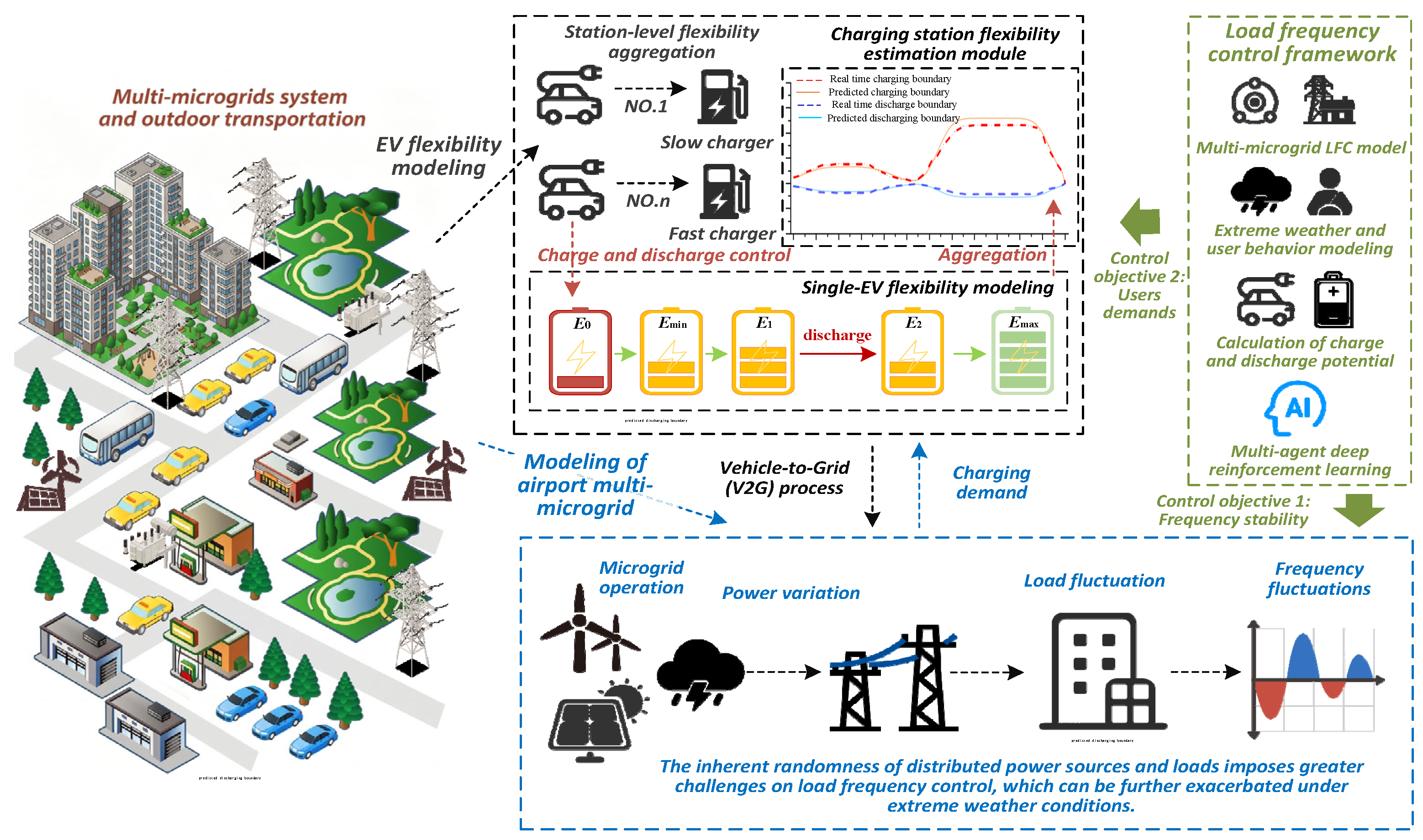
From the perspective of load frequency control, the MMG system is subject to stochastic disturbances arising from variable renewable generation and fluctuating loads, resulting in frequency deviations in each microgrid and power exchanges along tie-lines. A MA-SAC controller is deployed on top of this physical layer. Each agent observes local frequency deviations, tie-line power flows, and the real-time charging/discharging bounds of FCSs and SCSs in its microgrid, and outputs coordinated control actions for MTs and EV charging stations. As a result, the effective V2G capability—explicitly modeled as a function of charging infrastructure type, user time–energy demands, and weather scenario—directly constrains and shapes the control actions available to the MA-SAC-based LFC. Figure 1 conceptually illustrates this overall framework, showing how the electrified transportation system, heterogeneous EV users, FCSs/SCSs, normal and extreme operating conditions, and multi-agent frequency controllers are integrated into a unified control-oriented model.

3. Detailed Modeling and Scenario Characterization

3.1. Frequency Dynamics Model of MMG

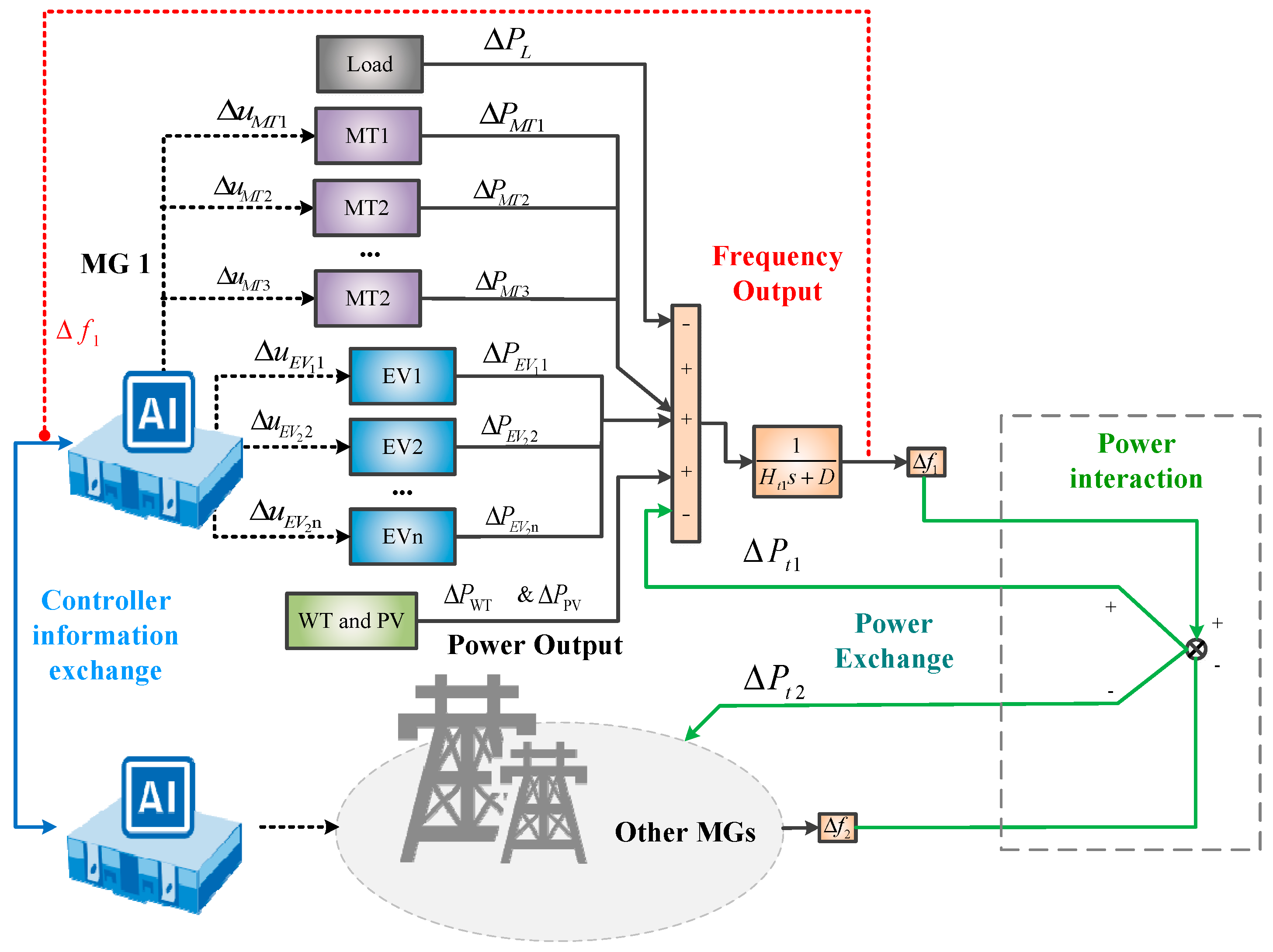
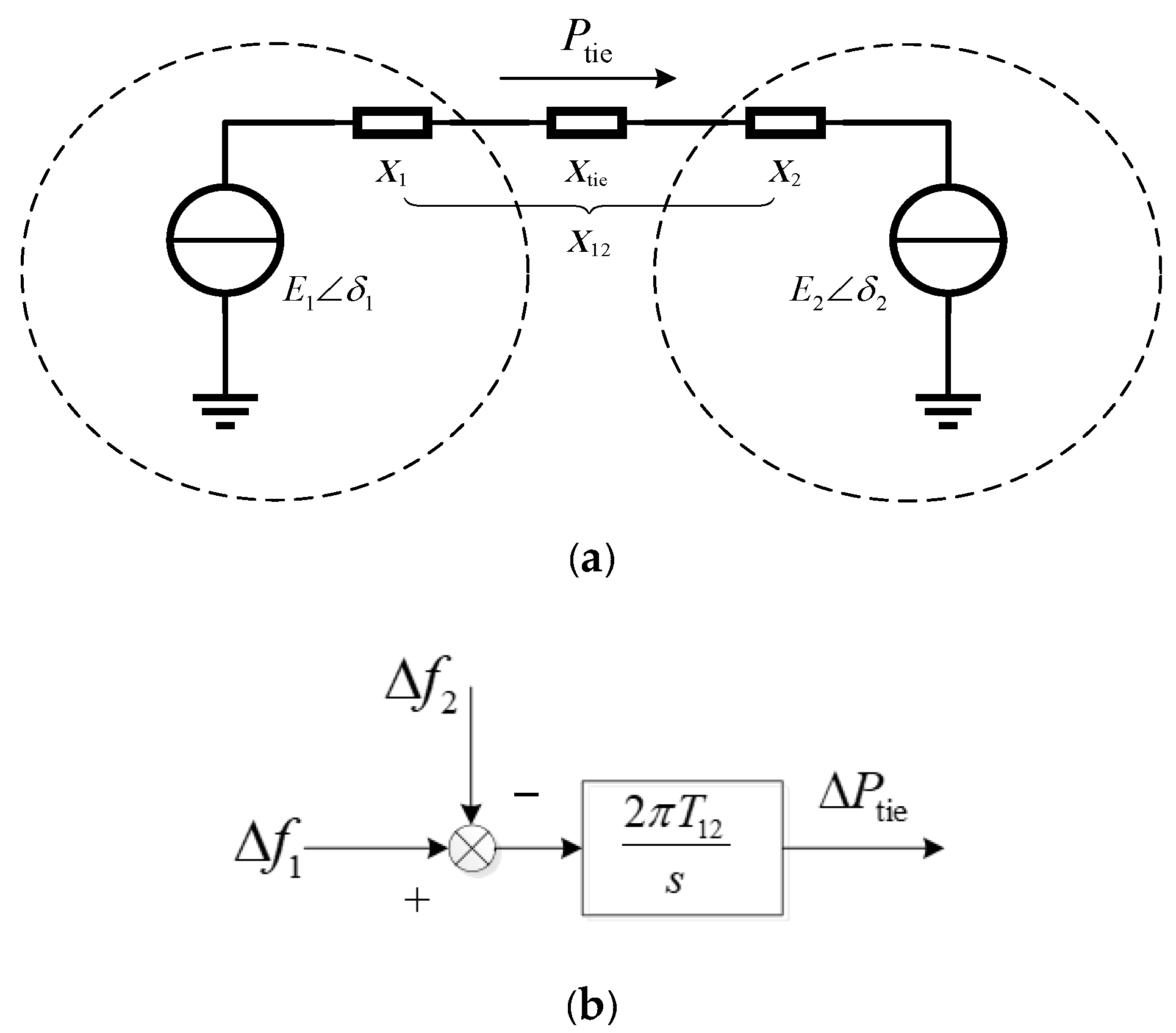
Renewable energy sources’ inherent variability and uncertainty introduce power fluctuations, regarded as disturbances within the microgrid, leading to frequency deviations. In this study, these fluctuations are modeled as disturbances affecting the LFC of the microgrid (MG). An MG with wind power distribution and its LFC is focused on, and the primary frequency regulator is MT. Each MG consists of an EV station, load, MT, wind power (WT), and photovoltaic (PV) systems. In Figure 2, ΔPL is the load power disturbance, ΔPWT and ΔPPV are the wind power and photovoltaic power disturbances, respectively, ΔPMT is the variation in the power of MT, and ΔPEV is the variation in the power of EV. The AI controller generates control signals, denoted as ΔuMTi and ΔuEVi, to regulate the outputs of the MTs and EVs based on the frequency deviation. Furthermore, Δf1 and Δf2 represent the frequency deviations of MG 1 and other connected MGs. ΔPti is the tie-line power variation, Ht is the inertia parameter, and D is the damping coefficient of the system. In order to determine the tie-line power variation, the coupling link takes into account the frequency fluctuations that take place between MGs.
Δ P t i = i i T s i j s ( Δ f i Δ f j )
In Figure 3a,b, ΔPti is the tie-line power variation, and Tsij is the parameter of the coupling link; from Equation (1), it is clear that: under the following conditions: MG i does not output power to the tie-line if ΔPti = 0, outputs positive power to the tie-line if ΔPti > 0, and sends negative power to the tie-line if ΔPti < 0. Each MA-SAC agent is responsible for sharing the important information-based decision, and this phenomenon is illustrated in Figure 2. The blue line in Figure 2 indicates the connection between the MA-SAC controller and MGs, while the green lines indicate the power flow among MGs associated through the coupling link. The red lines indicate the frequency deviations of each MG, and its feed is backed up to the MA-SAC controller to share important information.
MA-SAC will work enough to achieve the overall stability of the MG. And for getting information about the normal working conditions of MG, the information transmission will work. Every MG will work as expected and achieve stability under negligible disturbances. When a heavy fault occurs in one MG, the controller will be able to stabilize the system through coordinated control, which is an attractive and unique feature of MA-SAC.

3.2. Modeling of Charging Stations and User Demands

In a typical urban MMG scenario, EVs are mainly connected through two types of charging infrastructure: FCSs and SCSs. These two types differ significantly in terms of power rating, typical parking duration, and their capability to participate in frequency regulation. FCSs are characterized by high power ratings and rapid charging, and are usually located in office districts, commercial areas, or urban fast-charging nodes. They are suitable for short-term, high-power regulation. SCSs, by contrast, have medium-to-low power ratings and are typically installed in residential areas or long-term parking lots; they are more suitable for medium- to long-term energy balancing and gradual regulation. Based on this classification, user time requirements and energy requirements are incorporated into the modeling framework. To accurately reflect real-world scenarios, our framework explicitly accounts for the heterogeneity of individual EVs, where parameters such as battery capacities, maximum charging rates, and user-specific arrival/departure times are considered at the individual vehicle level. We first derive the charging/discharging margin at the individual EV level, and then aggregate it to obtain the real-time charging/discharging capacity of each charging station. This aggregated capacity provides operational constraints for the subsequent frequency control model.
And Cn denotes the battery capacity of n-th EV, and SOCn(t) is SOC at time t. The basic physical constraint on SOC is:
S O C n , min S O C n ( t ) S O C n , max
where SOCn,min and SOCn,max denote the minimum and maximum allowable SOC limits for the battery, respectively, to ensure safety and lifetime considerations. From the user’s perspective, there also exists an expected SOC at the time of departure from the charging station, denoted by SOCn,exp, which is determined by the energy required for the subsequent trip and the desired safety margin. Hence, the following condition must be satisfied:
S O C n ( T n dep ) S O C n , exp
where Tndep is the planned departure time of the n-th EV from the charging station.
The quantity SOCnexp is directly related to the energy demand of the upcoming trip. Let the travel distance from the charging station to the next destination be Ln. Denote by Pmile the energy consumption per kilometer under free-flow conditions, and by Pextra the additional average power consumption under congestion, with tcon being the congestion duration. Then, the SOC consumption for this trip can be approximated as:
Δ S O C n = P mile L n + P extra t con
Meanwhile, in order to ensure that the SOC upon arrival at the destination does not fall below a given safety threshold SOCn,A,min, the expected departure SOC should satisfy:
S O C n , exp S O C n , A , min + Δ S O C n
These equations thus establish a quantitative relationship from “travel distance–traffic condition–safety requirement” to SOCn,exp. Different users, characterized by different trip lengths, congestion expectations, and safety preferences, will have different values of SOCn,exp, thereby reflecting heterogeneity in energy demand.
With respect to time requirements, let Tnarr and Tndep denote the arrival and departure time of the n-th EV at/from the charging station. The total parking duration is:
Δ t n stay = T n dep T n arr
At a given time t (with TnarrtTndep), the remaining parking time is:
Δ t n rem = T n dep t
If the minimum time required to charge the EV from its current SOCn(t) to the expected SOCn,exp is:
t n req = ( S O C n , exp S O C n ( t ) ) C n p n , c
where pn,c denotes the rated charging power of the n-th EV. It should be noted that Equation (8) adopts a simplified linear charging assumption (constant power) to maintain macroscopic computational tractability. In practice, FCSs with high pn,c lead to a small tnreq, but their short parking durations highly constrain the time margin, whereas SCSs provide massive time margins suitable for long-term regulation. Furthermore, this framework is highly modular; in real-world deployments, tnreq can be directly provided by the EV’s Battery Management System (BMS), which inherently accounts for exact nonlinear charging curves without altering the core control logic.
Then, when Δtnrem is close to or less than tnreq, the EV has almost no temporal flexibility, and must charge at a relatively high-power level in order to meet SOCn,exp by the departure time. Conversely, if Δtnremtnreq, there exists substantial temporal flexibility, allowing the charging power to be reduced or even short periods of discharging to participate in frequency regulation. To capture this flexibility, a time margin factor is introduced:
δ n ( t ) = max { 0 , Δ t n rem t n req Δ t n rem } , 0 δ n ( t ) 1 .
The larger δn(t) is, the more temporal margin is available for frequency regulation while still satisfying the user’s departure SOC requirement; δn(t) = 0 implies effectively no flexibility. Crucially, δn(t) serves as a vital bridge within our hierarchical control architecture: while the MA-SAC agent determines the macroscopic aggregated power regulation command at the top level, the local charging station controller at the bottom level directly applies δn(t) as a dynamic priority index to allocate this macroscopic command among individual EVs. To strictly protect user privacy, the calculation of δn(t) is performed entirely within the local system, and raw user data is never uploaded to external servers.
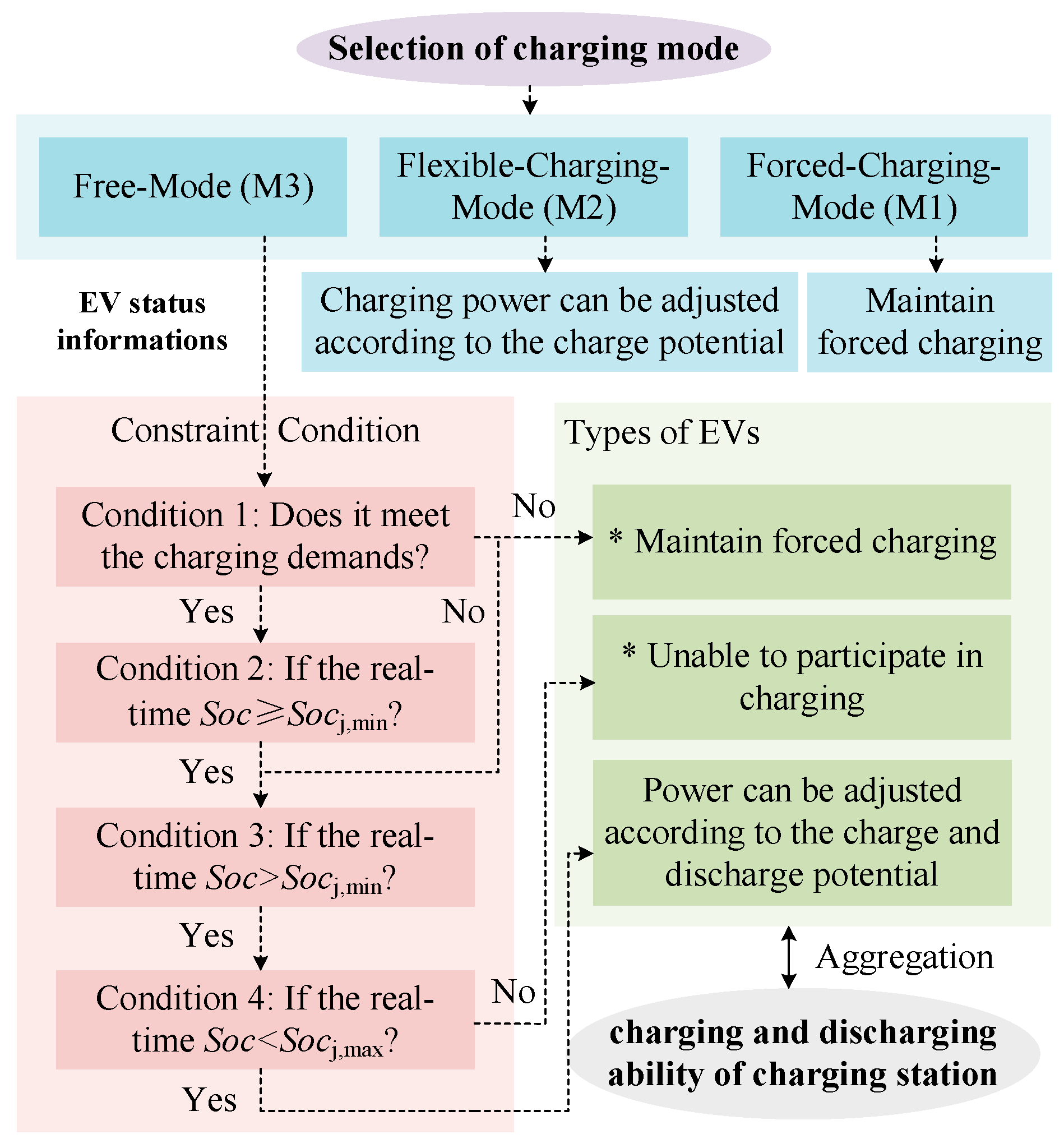
On top of the time and energy constraints discussed above, and taking into account users’ subjective willingness to participate in V2G, the charging behavior of EVs can be classified into three typical modes (consistent with realistic choices in charging applications) [33,34], as shown in Figure 4. By empowering users with the autonomy to select these charging modes, and by strictly enforcing expected departure SOCs to minimize unnecessary deep discharging, the framework inherently provides macroscopic protection for battery State of Health (SOH) without requiring complex electrochemical degradation models.
  • Mandatory charging mode (M1): Designed specifically to protect the rights of users with urgent travel needs (e.g., in business areas or temporary emergencies), this mode ensures charging is completed as fast as possible. The user is only concerned with charging as quickly as possible and does not accept discharging. The EV is expected to reach a SOC close to SOCn,max within a relatively short time. Under this mode, the EV performs only charging operations, and its power adjustment flexibility is very limited.
  • Flexible charging mode (M2): The user allows moderate adjustment of the charging power, provided that the departure time remains unchanged and the final SOC is no lower than (or slightly higher than) SOCn,exp. The EV can thus offer certain peak-shaving and valley-filling capability by modulating its charging power, but does not participate in discharging.
  • Bidirectional participation mode (M3): The user accepts V2G participation, as long as the departure SOC requirement is met. The EV is allowed to both charge and discharge during the parking period. Under this mode, the EV provides bidirectional regulation capability and becomes an important V2G resource for frequency control.
Combining SOC constraints, the time margin factor δn(t), and the charging mode selection, the maximum feasible charging power pnch(t) and discharging power pndis(t) for each EV can be determined:
  • If the user selects mode M1, or δn(t) is close to zero and the current SOC is significantly lower than SOCn,exp, the EV is effectively in a “mandatory charging” state. This condition does not indicate a failure in load planning; rather, it means the remaining charging time is just enough to reach the target SOC. Consequently, the control strategy prioritizes the user’s charging demand by disabling discharging participation, and the available discharging power is approximately zero, requiring the vehicle to charge near its rated power.
  • If the user selects mode M2 and δn(t) is relatively large, the EV has “downward flexibility” in charging power. It can reduce charging power within a certain range, without changing the departure time, in order to assist in smoothing system load.
  • If the user selects mode M3 and SOCn(t) is significantly higher than SOCn,exp while a substantial time margin exists, then, subject to (2)–(5), a nonzero discharging power can be allocated to the EV, thereby enabling bidirectional frequency regulation.
To evaluate the charging and discharging capacities of charging stations, EVs need to be integrated into the grid as aggregated units. The application of Minkowski addition enables the expansion of multiple variable spaces. By conducting the Minkowski sum on two spaces, a unified boundary is obtained, which allows EVs to be regarded as generalized energy storage systems. As a result, the individual variable domains of EVs can be mapped into a hypercube space, ensuring inter-variable constraints are preserved and charging/discharging decisions remain feasible. This mapping allows the hypercube space to include all possible charging and discharging decisions within the charging station, with the parameters of the generalized energy storage unit (i.e., the charging station) defining the charging and discharging margins of the EV cluster. The parameters { P j , t ch , max , P j , t d i s , max , S j , t max , S j , t min } are designated as the CS’s parameters, which are determined by (10). Furthermore, the EV cluster’s variable space can be compressed into the charging station’s variable space, as expressed in Equation (11).
P j , t c h , max = n N j E V p max , n c h X n , t d i s P j , t d i s , max = n N j E V p max , n d i s X n , t d i s S j , t min = n N j E V s n min X n , t S j , t max = n N j E V s n max X n , t
0 P j , t c h P j , t c h , max 0 P j , t d i s P j , t d i s , max S j , t min S j , t S j , t max
where P j , t c h and P j , t d i s denote the charging and discharging power of the charging station j at t. P j , t c h , max and P j , t d i s , max are the maximum charging and discharging power. Sj,t is the capacity of the charging station. S j , t max and S j , t min are the limitations of the charging station capacity. And the symbols of lowercase letters are the corresponding indicators for individual EVs. Xn,t is the grid connection status of EVs. X n , t d i s = 1 and X n , t c h = 1 represent that EVs can discharge and charge, while if it is 0, there is no corresponding capacity.
Thus, the charging station’s charging and discharging margins provide essential data for coordinated microgrid control. The system prioritizes user demand over grid requirements, but when sufficient discharge margin exists, the charging station can also support auxiliary grid services.

3.3. Model Adaptation Under Extreme Weather Conditions

Under extreme weather conditions, the parameters and effective domains of the normal-condition model in Section 3.2 are modified rather than rebuilt. In this work, heavy rainfall is selected as the representative extreme weather scenario for detailed modeling and analysis, as it has a direct and significant impact on urban travel behavior and EV distribution. Specifically, the considered scenario assumes a severe rainfall intensity (e.g., black rainstorm conditions associated with work suspensions and school closures) that is sufficient to substantially reduce urban mobility. Under such extreme conditions, heavy rain tends to reduce non-essential trips, increases the probability that users stay at home, and shortens the effective operating time of outdoor activities. As a consequence, fewer EVs are connected to FCSs in work and commercial areas during daytime, while more EVs remain parked for longer periods at slow charging stations in residential areas. This leads to a spatial redistribution of EVs from FCSs to SCSs, and typically increases parking durations in residential SCSs, while moderate rainfall might induce users to prefer private EVs over public transport. It should be noted that this study focuses exclusively on private EVs; large electric public transit (e.g., electric buses) typically relies on dedicated charging depots and thus does not directly interfere with the charging infrastructure modeled here, despite also being affected by extreme weather. Therefore, the severe weather assumption here specifically emphasizes the increase in long-term residential parking and the reduction of daytime workplace EV aggregation.
At the same time, adverse weather increases user conservativeness regarding SOC. To cope with unpredictable congestion, longer travel times, and higher HVAC usage (which is also highly prevalent during other extreme weather events such as heat waves or cold spells), users tend to raise their expected departure SOCn,exp and the implicit safety threshold at arrival. In terms of the model in Section 3.2, this corresponds to upward shifts of SOCn,exp and SOCn,A,min, and in cold conditions, an effective narrowing of the allowable SOC interval [SOCn,min, SOCn,max]. Consequently, the individual feasible power intervals shrink on the discharging side, especially for users in bidirectional mode (M3). Combined with the changes in arrival/departure times (Tnarr, Tndep), the remaining parking time Δtnrem and therefore the time margin factor δn(t) are also altered: for FCSs in work areas, both the number of connected EVs and δn(t) typically decrease, while for residential SCSs, Δtnstay and δn(t) may increase due to prolonged home parking.
When these parameter shifts are propagated through the Minkowski aggregation process, the station-level V2G bounds are modified accordingly. Qualitatively, heavy rainfall and similar extreme conditions reduce the short-term V2G bounds of FCSs in work and commercial areas, while in some periods, they enhance or at least stabilize the medium- to long-term regulation potential of SCSs in residential areas due to longer and denser parking. Importantly, the proposed framework is designed with strong adaptability; its core objective is not to depend on a single fixed traffic assumption, but rather to evaluate how the coordinated control strategy dynamically responds to various weather-induced variations in V2G availability and user behavior. These changes directly affect the amount and distribution of controllable resources available to the MA-SAC-based load frequency control, and their impact will be further evaluated in the simulation studies in Section 5.

4. MA-SAC-Based Frequency Control Framework

4.1. Brief Overview of SAC

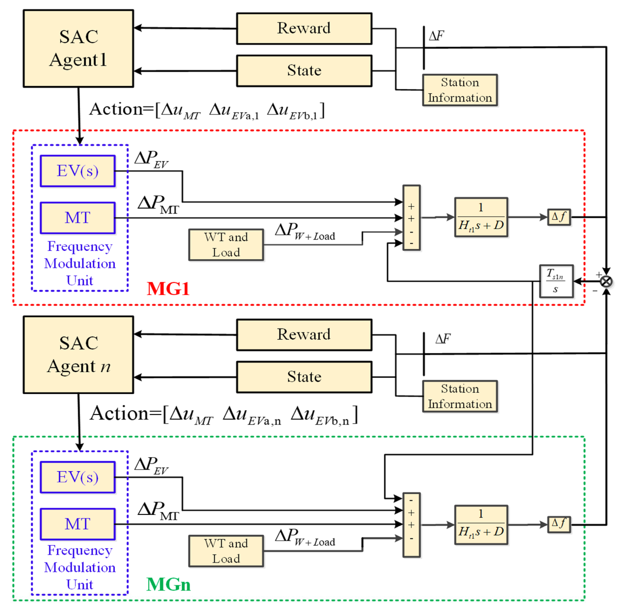
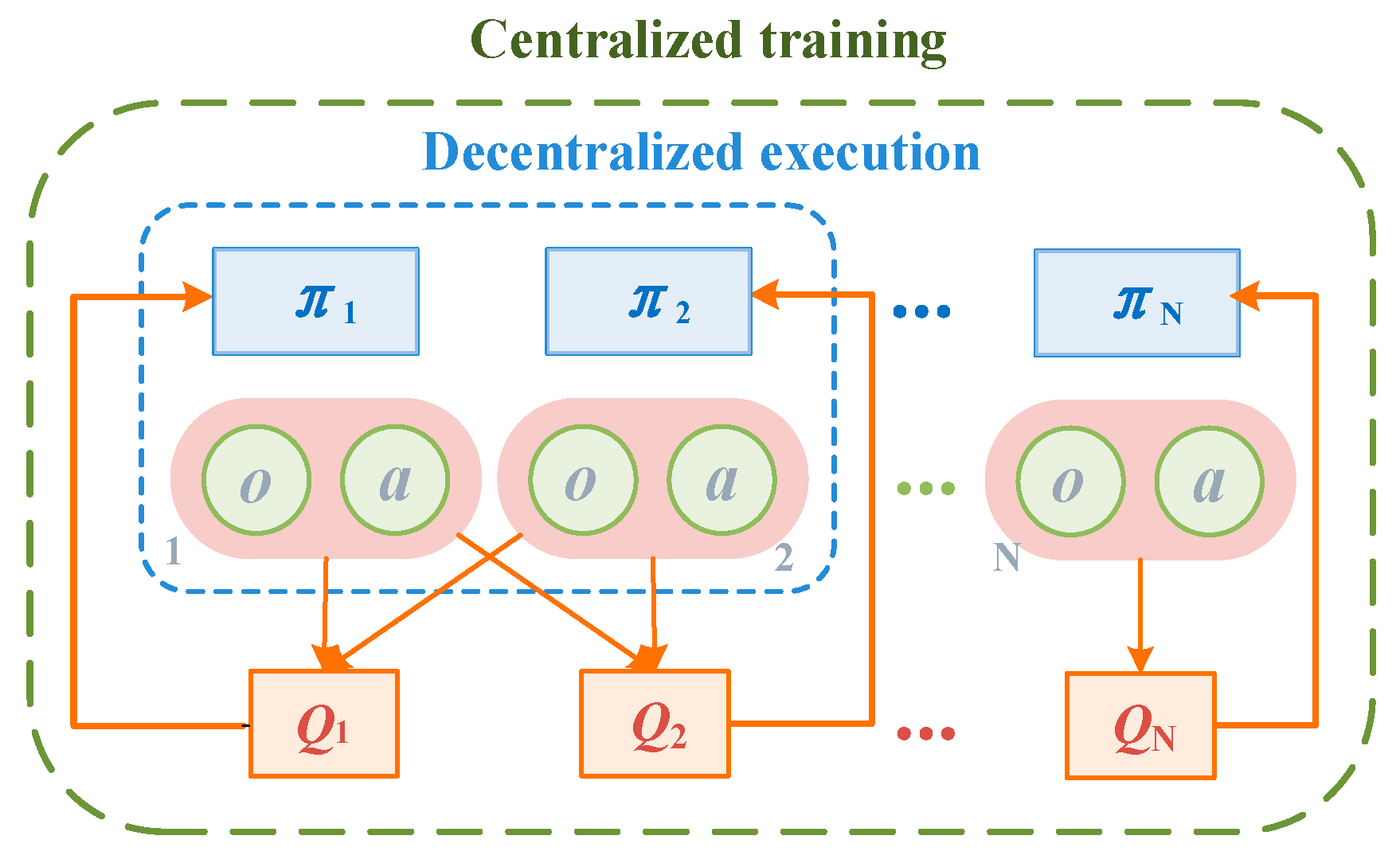
The SAC technique bridges the gap between stochastic policy optimization and DDPG-style approaches by optimizing a stochastic policy in an off-policy manner. It uses the clipped Double-Q method, and because SAC policies are inherently stochastic, it also benefits from target policy smoothing. A key component of SAC is the regularization of entropy. Policy training aims to optimize the trade-off between expected return and policy entropy, which is a measure of randomness [14,33,34]. The balance between exploration and exploitation is a fundamental aspect of reinforcement learning, where increased entropy facilitates broader exploration, thereby expediting the learning process. Maintaining an optimal entropy level prevents premature convergence to suboptimal solutions, ensuring a more effective policy. Unlike conventional reinforcement learning algorithms that solely focus on performance optimization, the SAC algorithm optimizes both the objective function and the entropy of actions to enhance exploration efficiency. The MA-SAC framework operates based on the principle of “centralized training and decentralized execution,” enabling the optimization of overall system objectives in multi-agent systems, as illustrated in Figure 5.

4.2. Multi-Agent Control Architecture and Hierarchy

Figure 6 depicts the link structure between Agent 1 in MG-1 and the related j groups of agents. The frequency deviation established in the MMG, the input fed into Agent 1 will be ΔF = [Δf1, Δf2, …, Δfi] of the connected MG and MG1, and the output action set ΔUi = (ΔuMTi, ΔuEVai, ΔuEVbi) of the MG’s agents next to MG1 and the agents of the other MGs are in the same boat. Collaboratively training every agent in the system can maximize the strategy’s collective reward and enable each set of controllers in the multi-agent system to operate in unison. If a MG’s frequency modulation unit malfunctions and loses its ability to adjust, coordinated regulation can also be utilized to preserve and guarantee the MMG stability as a whole. Furthermore, using Agent 1 in MG 1 as an example, the EV station’s upper and lower limit constraints, the frequency deviation set ΔF, and the set of agent actions ΔUi of the multi-agent system will be considered by the coordination control layer of this agent. Consequently, the control layer receives the real-time LFC signal ΔU1 to swiftly control each frequency control unit’s output power in MG1, attain power balance and stop frequency fluctuations in the system.

4.3. Design of State, Action, and Reward Functions

In a MMG, disturbances cause temporary frequency divergences among sub-microgrids before they gradually converge through coupling and control mechanisms; thus, the frequency deviation of MG1 is taken as a representative example for analysis. To summarize, the frequency deviation Δf(t) in real-time of the MG1, the action set of other agents, and the upper and lower limit constraint sets in real time of the stations’ charging power make up the state set of Agent 1 in MG 1. The state space can be analyzed as:
S = Δ f 1 ( t ) , Ω P E V + , Ω P E V Δ U 1 ( t ) , , Δ U j ( t )
Δ U 1 ( t ) = Δ U M T 1 ( t ) , Δ U E V a 1 ( t ) , Δ U E V b 1 ( t ) Δ U j ( t ) = Δ U M T j ( t ) , Δ U E V a j ( t ) , Δ U E V b j ( t )
Control signals real-time sets which are supplied to the MT and EV stations are represented by the joint action set A of Agent 1 controller’s output; so, the action space can be determined as:
A = Δ U M T ( t ) , Δ U E V a ( t ) , Δ U E V b ( t )
Additionally, Agent 1’s reward function might be created in the manner described below:
R 1 ( k ) = C 1 + F ( Δ f 1 ) + P ( Δ f 1 )
F ( Δ f 1 ) = μ 1 Δ f 1 Δ f 1 < 0.05 μ 2 Δ f 1 0.05 Δ f 1 < 0.1 μ 3 Δ f 1 0.1 Δ f 1 < 0.15 μ 4 Δ f 1 0.15 Δ f 1 0.2
P ( Δ f 1 ) = 0 Δ f 1 0.2 C 2 0.2 < Δ f 1  
R MG 1 = k = 0 T f / T s R 1 ( k )
where R1(k) represents the reward value obtained at step k in a training round, and C1 represents the fixed reward in the cycle process. If the total step length in a cycle is longer, the total value of the fixed reward will be more considerable, thus encouraging the agent to avoid the situation of training suspension as much as possible. χ stands for a fixed penalty factor, and Ff1) represents the reward value under different frequency fluctuation intervals, where Δf1 denotes the frequency deviation of MG1 taken as the representative microgrid in the reward-function formulation. Pf1) represents the termination penalty. When this penalty item is triggered, the system will automatically stop the training, and C2 represents the termination penalty value. RMG1 represents the total reward value accumulated during a round of training in MG1. In addition, μi are the penalty weights for Δf, and Tf and Ts are the simulation and agent sample times, respectively.
The rationale for employing such a composite reward function, rather than a single functional form, is to prevent the reinforcement learning agent from getting trapped in local optima due to sparse rewards. These sub-functions work synergistically to shape a dense and effective learning landscape for the singular goal of frequency regulation: the quadratic terms exponentially penalize large deviations to force immediate suppression of severe oscillations, while the piecewise functions provide fine-grained, interval-specific guidance aligned with grid compliance standards. Furthermore, the constant term acts as a survival reward to encourage long-term stability, and the termination penalty strictly teaches the agent to avoid catastrophic system collapse. Together, they ensure fast, safe, and globally optimal convergence.
To ensure reproducibility and provide a clear view of the computational framework, the implementation details of the MA-SAC training process are explicitly defined. The neural network architecture for the Critic utilizes a Twin Delayed Q-network structure to mitigate overestimation. Both Critic networks process the 12-dimensional state input through a fully connected (FC) layer of 400 neurons, followed by a ReLU activation and another 300-neuron FC layer. The 3-dimensional action input is processed through a 300-neuron FC layer. The state and action features are then added, passed through a ReLU activation, and mapped to a single Q-value output. The Actor network employs a stochastic Gaussian policy. The shared state features are extracted via a 400-neuron FC layer with ReLU activation, which then splits into a mean branch and a standard deviation branch. Both branches utilize a 300-neuron FC layer with ReLU activation, outputting a 3-dimensional vector (with a Softplus activation for the standard deviation to ensure positivity).
During the training phase, both Actor and Critic networks are optimized using the Adam optimizer with a learning rate of 10−3 and a gradient threshold of 1. L2 regularization factors are set to 10−5 for the Actor and 2 × 10⁻⁴ for the Critic. The experience replay buffer is configured with a capacity of 106 transitions, from which mini-batches of size 128 are sampled. The discount factor γ is set to 0.999, and the target networks are updated using a soft smoothing factor τ = 10−3. The entropy temperature parameter is automatically tuned during training to balance exploration and exploitation. To guarantee reproducibility, the random seed is fixed at 0. The training is conducted over a maximum of 3000 episodes, with each episode containing up to 400 steps (derived from a simulation time Tf = 20s and a sample time Ts = 0.05). Training terminates early if the average reward over a 100-episode window reaches the convergence criteria. While the offline training process requires substantial computational overhead, the online execution only involves forward passes through the trained Actor networks, ensuring real-time applicability for load frequency control.

5. Simulation Results

5.1. Simulation System Settings

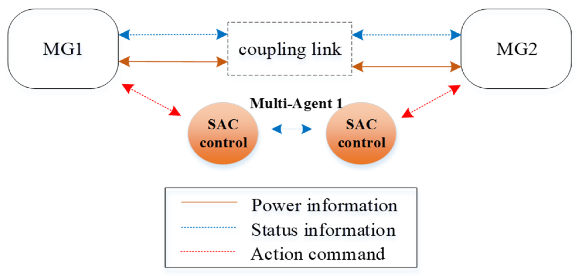
A MMG system composed of two sub-microgrids is designed to evaluate the effectiveness of the proposed control method. The system consists of MG1 and MG2, where MG1 is located in the working area and MG2 is located in the residential area. Each sub-microgrid has the capability of power transmission and information exchange, enabling cooperative control through communication. In this dual-microgrid system, the two sub-microgrids form a multi-agent system based on the proposed algorithm. Each sub-microgrid is managed by an independent MA-SAC controller, and the controllers exchange state data to develop optimized strategies. This coordination ensures effective power transfer and overall system stability. The organizational structure of the dual-microgrid system is shown in Figure 7.
The simulations were conducted using MATLAB/Simulink R2024b on a 64-bit Windows operating system equipped with an Intel Core i7-14700HX CPU (2.10 GHz), 16 GB RAM, and an NVIDIA GeForce RTX 4070 Laptop GPU (8 GB). To evaluate the temporal variation in EV aggregation behavior and V2G regulation capability throughout the day, three representative operating time points (00:00, 12:00, and 19:00) are selected for the simulation analysis. Specifically, 00:00 represents the nighttime residential parking period with relatively high long-term EV availability, 12:00 corresponds to the daytime working and commercial activity period dominated by fast-charging demand, and 19:00 reflects the evening commuting transition period associated with mixed charging behaviors and EV redistribution between residential and working areas. These representative operating conditions help evaluate the adaptability of the proposed control framework under different temporal EV distribution characteristics and V2G availability levels.
To quantify the control performance, three indicators are employed in this study: (1) maximum frequency deviation (Hz)—the peak absolute deviation during the simulation; (2) average frequency deviation (Hz)—the mean absolute deviation over the entire simulation period; and (3) excellent rate (%)—the proportion of time during which the frequency deviation remains strictly within the ±0.10 Hz compliance band. The excellent rate is introduced to capture the temporal consistency of high-quality regulation, complementing conventional extreme-value and average metrics.

5.2. V2G Bounds and Frequency Control Under Normal Conditions

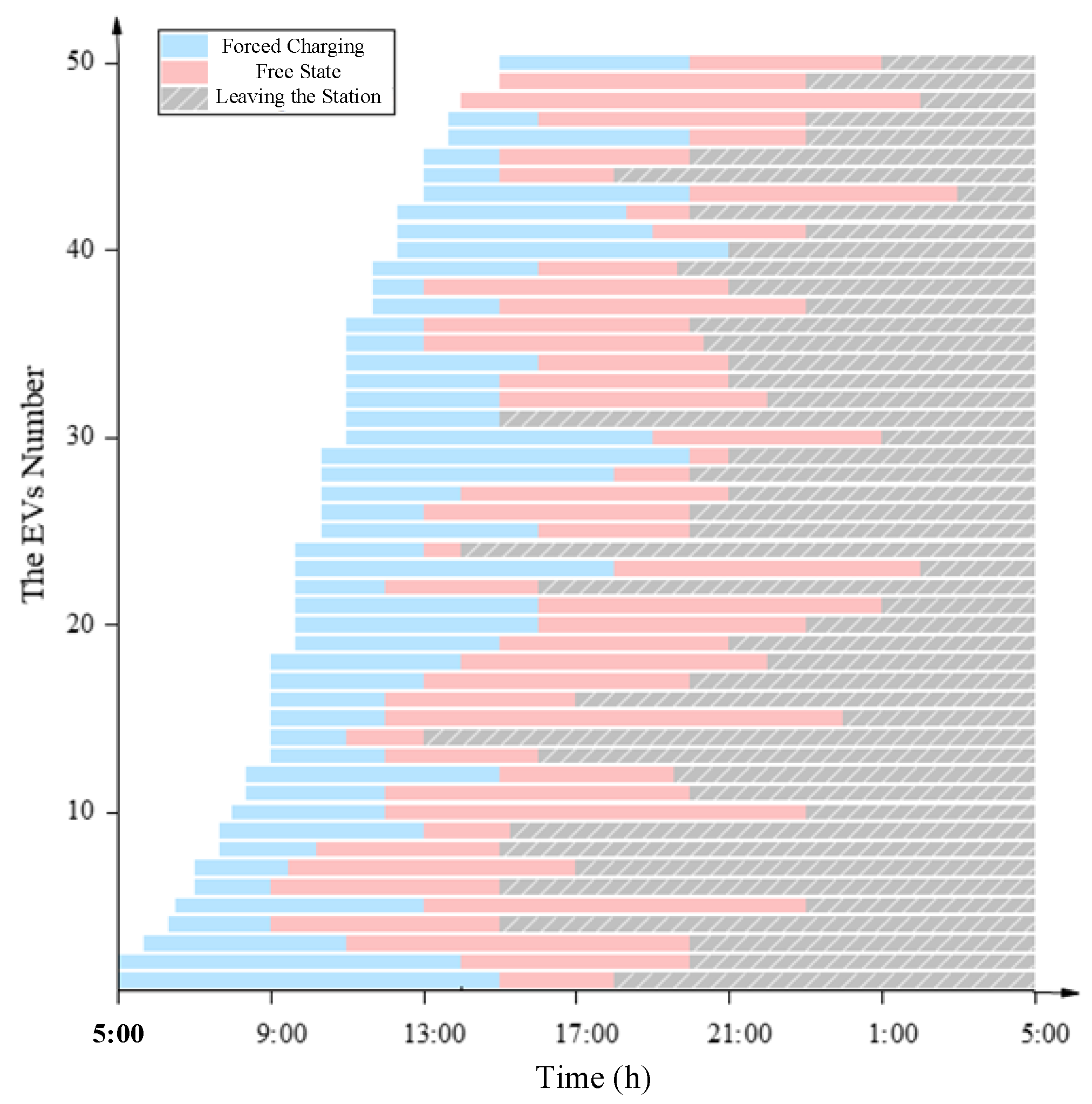
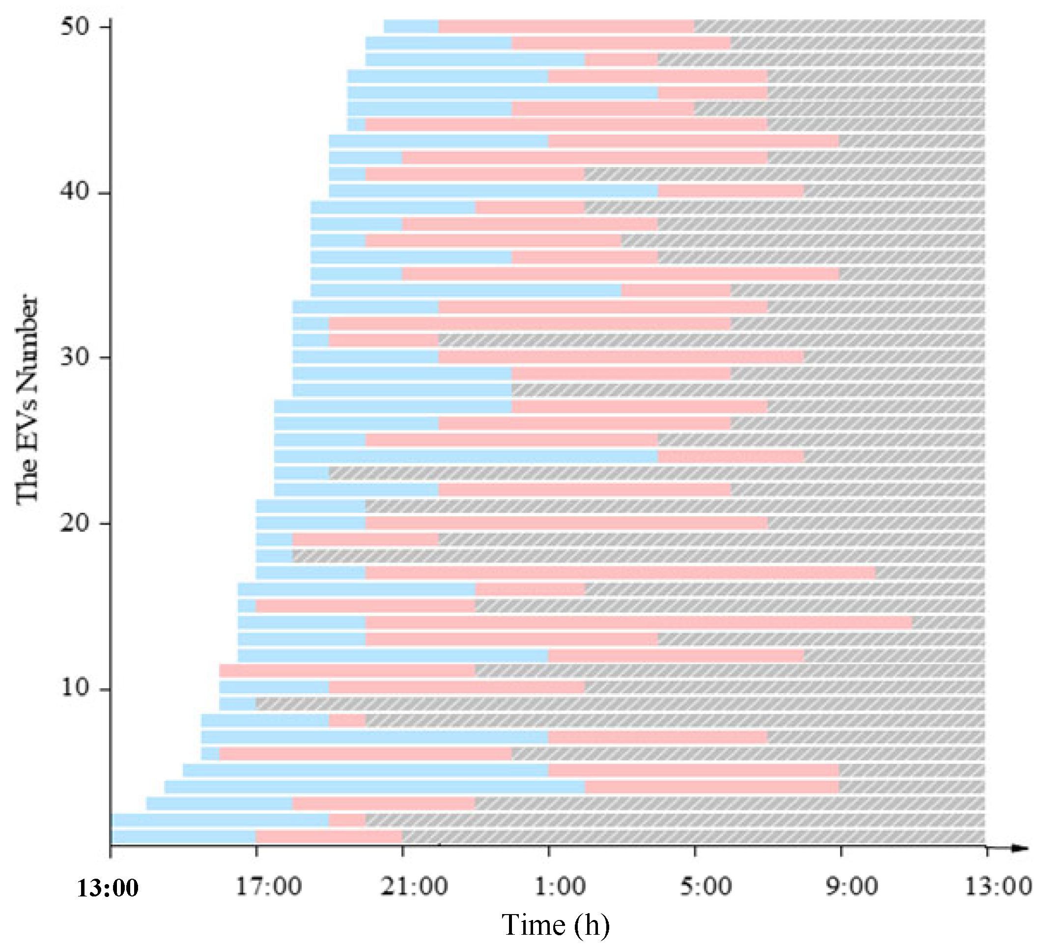
Under normal weather conditions, the MMG system operates according to a typical weekday pattern. MG1 represents the workplace microgrid, equipped primarily with FCSs, while MG2 corresponds to the residential microgrid, equipped mainly with SCSs [35]. Figure 8 and Figure 9 display the intraday evolution of EV numbers and states within MG1 and MG2, respectively. At 00:00, the majority of EVs are parked in the residential SCS of MG2, resulting in high charging/discharging margins, whereas the FCS in MG1 has scarce connected vehicles and limited V2G bounds. After 12:00, EV concentration shifts to the workplace area, expanding the V2G bounds of MG1’s FCS and simultaneously reducing those of MG2’s SCS. By 19:00, a gradual return of EVs to the residential area is observed, with the V2G bounds of both station types transitioning toward the nighttime pattern.
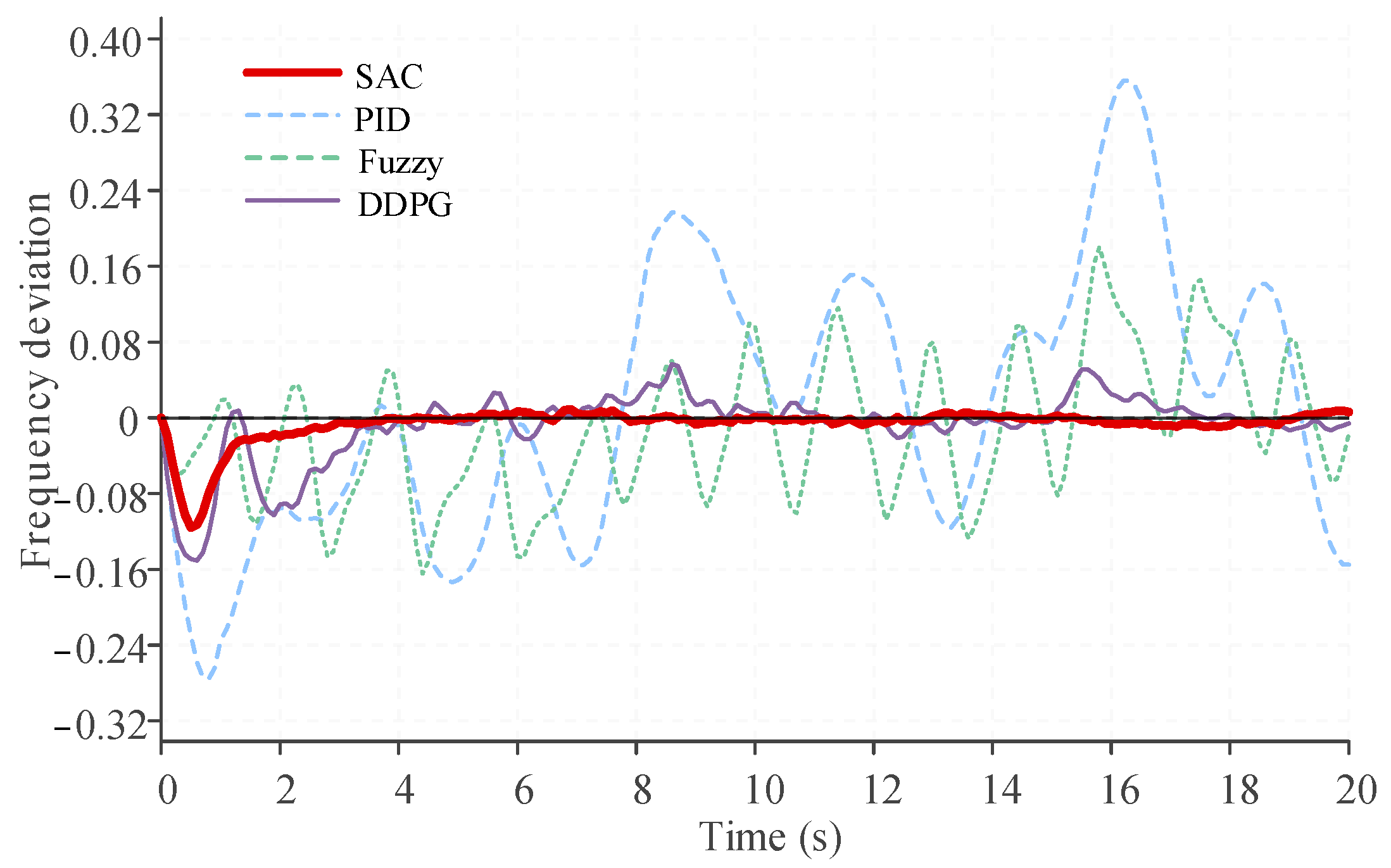
Random load and wind power disturbances were then imposed at 12:00. Figure 10 shows the frequency response of MG1 under different controllers. The corresponding numerical indicators are summarized in Table 1. As reported in Table 1, under PID control, the average frequency deviation is 0.1161 Hz and the excellent rate is 46.27%. Fuzzy control improves these to 0.0614 Hz and 81.09%, respectively. MA-DDPG further reduces the average deviation to 0.02176 Hz with a 95.52% excellent rate. The proposed MA-SAC achieves the lowest average deviation of 0.00876 Hz and the highest excellent rate of 98.51%. A similar ranking is observed for the maximum deviation: 0.3563 Hz (PID), 0.1802 Hz (Fuzzy), 0.1508 Hz (MA-DDPG), and 0.1158 Hz (MA-SAC).
To examine the effect of intraday V2G variability, the same disturbances were applied at 00:00 and 19:00. The resulting indicators are given in Table 2 and Table 3. During these periods, when V2G resources in MG1 are limited due to EV migration to residential areas, PID and fuzzy controllers exhibit maximum deviations up to 0.4702 Hz and 0.5970 Hz, with excellent rates dropping to 41.12% and 35.09%. MA-DDPG shows moderate degradation, while MA-SAC maintains an excellent rate of 97.12% and 95.45%, with maximum deviations of 0.1218 Hz and 0.1346 Hz, respectively.

5.3. V2G Changes and Frequency Control Under Extreme Weather

Under the heavy rainfall scenario, the spatiotemporal distribution of EVs shifts: daytime FCS connectivity in MG1 decreases, while long-term parking in the residential SCS of MG2 increases. Users also raise their expected departure SOC, narrowing the feasible discharging depth. Identical random disturbances were applied at 12:00 under this extreme weather. The performance indicators are listed in Table 4. The maximum deviation reaches 0.7013 Hz for PID and 0.3155 Hz for Fuzzy, with excellent rates falling to 31.77% and 60.01%. MA-DDPG limits the maximum deviation to 0.2388 Hz with a 78.52% excellent rate. MA-SAC keeps the maximum deviation at 0.1406 Hz and the excellent rate at 91.47%.

6. Discussion

The simulation results reveal several important performance characteristics of the proposed MA-SAC-based LFC strategy. First, under normal conditions, the V2G bounds dynamically reconstructed from user time/energy demands and charging mode choices (Figure 8 and Figure 9) are highly consistent with the spatiotemporal EV mobility model in Section 3.2, confirming that the framework realistically captures intraday flexibility variations. Building on this accurate situational awareness, MA-SAC consistently outperforms PID, Fuzzy, and MA-DDPG across all tested time points. When V2G resources are abundant (12:00), MA-SAC reduces the maximum deviation by over 80% relative to PID and achieves an excellent rate of 98.51%, demonstrating its ability to fully exploit heterogeneous station capabilities. More importantly, during periods of scarce V2G resources, such as nighttime (00:00) and the evening transition (19:00), traditional controllers suffer severe degradation (excellent rates as low as 35.09% for PID), while MA-SAC sustains excellent rates above 95%. This robustness stems from the multi-agent architecture’s ability to coordinate local micro-turbine output, tie-line power, and indirect support from neighboring microgrids when local V2G is insufficient. Thus, the controller effectively decouples short-term frequency stability from instantaneous V2G availability.
Second, under extreme weather conditions represented by heavy rainfall, the V2G margin of workplace FCSs shrinks, and user conservatism further constrains the available regulation capacity. PID and Fuzzy controllers exhibit marked performance drops (PID excellent rate falling to 31.77%). MA-DDPG, despite better baseline performance, also sees its excellent rate decrease to 78.52%. In contrast, MA-SAC adapts to the altered V2G bounds with only a minor performance decline, maintaining an excellent rate of 91.47% and confining the maximum deviation well within acceptable limits. This demonstrates that the MA-SAC agent has internalized weather-induced variations in both resource availability and user preferences during training, and can autonomously recalibrate its reliance on MT and tie-line support without compromising user travel requirements.
More broadly, the consistent superiority of MA-SAC over MA-DDPG and model-based methods highlights the value of maximum-entropy deep reinforcement learning for managing high-dimensional stochastic V2G resources. The composite reward function, which combines piecewise penalties, quadratic terms, survival bonuses, and termination penalties, provides a dense learning signal that prevents local optima and accelerates convergence. The newly introduced “Excellent rate” metric further substantiates this advantage by quantifying temporal regulation quality, showing that MA-SAC not only suppresses peak deviations but also ensures prolonged, grid-code-compliant operation. Nevertheless, certain limitations should be acknowledged. The present study is confined to a two-microgrid system, and scaling to city-level multi-microgrid networks with complex topologies requires further investigation. Extreme weather modeling currently focuses on heavy rainfall; other events such as heatwaves or cold spells may trigger different behavioral patterns in EV users. Finally, communication reliability and privacy-preserving mechanisms, though conceptually addressed, demand more rigorous integration in field deployments. These aspects will guide our future efforts toward a more comprehensive and deployment-ready intelligent frequency control framework.

7. Conclusions

Thus, an intelligent load frequency control strategy for MMG with V2G considering charging diversity and extreme weather is proposed. Through the simulation analysis, the following conclusions are drawn.
(1)
In terms of conventional control capability, the proposed MA-SAC controller demonstrates superior performance compared with PID, fuzzy control, and MA-DDPG. Under both normal and extreme weather conditions, the controller effectively suppresses frequency fluctuations and maintains system stability. Even when subjected to strong random disturbances, the maximum frequency deviation is almost confined within ±0.10 Hz, which is significantly better than traditional controllers.
(2)
In terms of flexible control capability, the paper establishes a stochastic charging/discharging boundary model that incorporates EV spatiotemporal mobility and user demands. By coordinating the diverse V2G bounds of FCSs and SCSs, the controller fully exploits the rapid regulation potential of EVs while safeguarding user demands. EVs can therefore participate in frequency regulation without unnecessary discharging. This improves the coordination between grid stability objectives and user preferences.
(3)
In terms of robustness under extreme scenarios, the MA-SAC controller adapts to variations in EV distribution and V2G bounds caused by heavy rainfall and other adverse conditions. Moreover, when communication delays are superimposed on extreme weather and limited V2G bounds, the controller continues to suppress oscillations and restore frequency within acceptable limits. This highlights its strong robustness and generalization ability across multi-scenario, multi-constraint operating environments.
Despite the effectiveness of the proposed strategy, this study has certain limitations that warrant future research. First, to address potential data security and communication vulnerabilities, advanced privacy-preserving technologies and more robust communication mechanisms will be integrated into the control framework. Second, future work will scale the proposed model to city-level large-scale interconnected systems involving a greater number of microgrids (e.g., over ten) with complex network topologies. Finally, we plan to incorporate the impacts of other extreme weather scenarios, such as heatwaves and cold spells, on EV user behaviors and energy demands, thereby further enhancing the comprehensive adaptability of the strategy.

Author Contributions

Conceptualization, P.F.; methodology, C.Z. and P.F.; software, C.Z.; validation, C.Z. and P.F.; formal analysis, C.Z. and P.F.; investigation, C.Z.; resources, P.F.; writing—original draft preparation, C.Z. and P.F.; writing—review and editing, P.F. and S.B.; visualization, C.Z. and P.F.; supervision, S.B. All authors have read and agreed to the published version of the manuscript.

Funding

This work was supported by The Hong Kong Polytechnic University under Project 686Y.

Data Availability Statement

The original contributions presented in this study are included in the article. Further inquiries can be directed to the corresponding author.

Acknowledgments

The authors would also like to acknowledge the support from the Undergraduate Research and Innovation Scheme (URIS) of The Hong Kong Polytechnic University under Project No. P0053580.

Conflicts of Interest

The authors declare that they have no known competing financial interests or personal relationships that could have appeared to influence the work reported in this paper.

References

  1. Zhou, B.; Zou, J.; Chung, C.Y.; Wang, H.; Liu, N.; Voropai, N.; Xu, D. Multi-microgrid Energy Management Systems: Architecture, Communication, and Scheduling Strategies. J. Mod. Power Syst. Clean Energy 2021, 9, 463–476. [Google Scholar] [CrossRef]
  2. Almihat, M.; Munda, J. Comprehensive Review on Challenges of Integration of Renewable Energy Systems into Microgrid. Sol. Energy Sustain. Dev. J. 2025, 14, 199–236. [Google Scholar] [CrossRef]
  3. Kumar, A.; Singh, A.R.; Raghav, L.P.; Deng, Y.; He, X.; Bansal, R.; Kumar, P.; Naidoo, R. State-of-the-art review on energy sharing and trading of resilient multi microgrids. iScience 2024, 27, 109549. [Google Scholar] [CrossRef] [PubMed]
  4. Ahmad, A.; Qin, Z.; Wijekoon, T.; Bauer, P. An Overview on medium voltage grid integration of Ultra-Fast charging stations: Current status and future trends. IEEE Open J. Ind. Electron. Soc. 2022, 3, 420–447. [Google Scholar] [CrossRef]
  5. Iqbal, S.; Xin, A.; Jan, M.U.; Abdelbaky, M.A.; Rehman, H.U.; Salman, S.; Rizvi, S.A.A.; Aurangzeb, M. Aggregation of EVs for Primary Frequency Control of an Industrial Microgrid by Implementing Grid Regulation & Charger Controller. IEEE Access 2020, 8, 141977–141989. [Google Scholar] [CrossRef]
  6. Ke, S.; Yang, J.; Chen, L.; Fan, P.; Shi, X.; Li, G.; Wu, F. A Frequency Control Strategy for EV Stations Based on MPC-VSG in Islanded Microgrids. IEEE Trans. Ind. Inform. 2024, 20, 1819–1831. [Google Scholar] [CrossRef]
  7. Rao, Y.; Yang, J.; Xiao, J.; Xu, B.; Liu, W.; Li, Y. A frequency control strategy for multimicrogrids with V2G based on the improved robust model predictive control. Energy 2021, 222, 119963. [Google Scholar] [CrossRef]
  8. Ding, L.; Ke, S.; Yang, J.; Shi, X.; Fan, P.; Crisostomi, E. A heuristic-fuzzy improved virtual synchronous generator control strategy for charging station frequency regulation. J. Energy Storage 2024, 99, 113411. [Google Scholar] [CrossRef]
  9. Jie, B.; Baba, J.; Kumada, A. Contribution to V2G System Frequency Regulation by Charging/Discharging Control of Aggregated EV Group. IEEE Trans. Ind. Appl. 2024, 60, 1129–1140. [Google Scholar] [CrossRef]
  10. Raju, G.V.; Srikanth, N.V. Frequency control of an islanded microgrid with multi-stage PID control approach using moth-flame optimization algorithm. Electr. Eng. Arch. Elektrotechnik 2025, 107, 8861–8878. [Google Scholar] [CrossRef]
  11. Khadanga, R.K.; Kumar, A.; Panda, S. Application of interval Type-2 Fuzzy PID Controller for frequency regulation of AC islanded microgrid using Modified Equilibrium Optimization Algorithm. Arab. J. Sci. Eng. 2021, 46, 9831–9847. [Google Scholar] [CrossRef]
  12. Khokhar, B.; Dahiya, S.; Parmar, K.P.S. Load Frequency Control of a Multi-Microgrid System Incorporating Electric Vehicles. Electr. Power Compon. Syst. 2021, 49, 867–883. [Google Scholar] [CrossRef]
  13. Minchala-Ávila, C.; Arévalo, P.; Ochoa-Correa, D. A Systematic Review of Model Predictive Control for Robust and Efficient Energy Management in Electric Vehicle Integration and V2G Applications. Modelling 2025, 6, 20. [Google Scholar] [CrossRef]
  14. Fan, P.; Ke, S.; Yang, J.; Li, R.; Li, Y.; Yang, S.; Liang, J.; Fan, H.; Li, T. A load frequency coordinated control strategy for multimicrogrids with V2G based on improved MA-DDPG. Int. J. Electr. Power Energy Syst. 2023, 146, 108765. [Google Scholar] [CrossRef]
  15. Alfaverh, F.; Denaï, M.; Sun, Y. Optimal vehicle-to-grid control for supplementary frequency regulation using deep reinforcement learning. Electr. Power Syst. Res. 2023, 214, 108949. [Google Scholar] [CrossRef]
  16. Prajapati, Y.R.; Kamat, V.N.; Patel, J. Load Frequency Control Under Restructured Power System Using Electrical Vehicle as Distributed Energy Source. J. Inst. Eng. India Ser. B 2020, 101, 379–387. [Google Scholar] [CrossRef]
  17. Kraiem, H.; Gadri, W.; Flah, A. Efficient Energy Management with Emphasis on EV Charging/Discharging Strategy. Eng. Technol. Appl. Sci. Res. 2024, 14, 13143–13147. [Google Scholar] [CrossRef]
  18. Shrivastava, S.; Khalid, S.; Nishad, D.K. Impact of EV interfacing on peak-shelving and frequency regulation in a microgrid. Sci. Rep. 2024, 14, 31514. [Google Scholar] [CrossRef]
  19. Alshareef, S.M. Voltage Sag Assessment, Detection, and Classification in Distribution Systems Embedded with Fast Charging Stations. IEEE Access 2023, 11, 89864–89880. [Google Scholar] [CrossRef]
  20. Al-Sultan, M.; Avci, İ. Advanced transmission line fault protection including the voltage sag. J. Renew. Sustain. Energy 2025, 17, 025502. [Google Scholar] [CrossRef]
  21. Dahmane, Y.; Chenouard, R.; Ghanes, M.; Ruiz, M.A. Optimal Electric Vehicle Fleet Charging Management with a Frequency Regulation Service. World Electr. Veh. J. 2023, 14, 152. [Google Scholar] [CrossRef]
  22. Shim, J.W.; Verbič, G.; Hur, K. Grid-supportive electric vehicle charging methodology with energy management for coordinated frequency control. IET Gener. Transm. Distrib. 2021, 15, 3474–3487. [Google Scholar] [CrossRef]
  23. Jie, B.; Fang, S.; Niu, T.; Baba, J.; Kumada, A. A Study on the V2G-based Frequency Fluctuations Suppression Considering the Uncertainty of EVs Charging Loads. In IEEE Transportation Electrification Conference and Expo (Online); IEEE: New York, NY, USA, 2025. [Google Scholar] [CrossRef]
  24. Alkhawaldeh, F.A.; Alomoush, M.I. Operational Optimization of Microgrids Integrating Electric Vehicles and Vehicle-to-Grid Impact. Energy Storage 2026, 8, e70328. [Google Scholar] [CrossRef]
  25. Dong, S.; Guo, S. Advancements, Challenges, and Future Trends of Vehicle-to-Grid Technologies: A Review. Energy Technol. 2025, 13, 2500481. [Google Scholar] [CrossRef]
  26. Liu, F.; Wei, Z.; Lin, Y.; Huang, X.; Li, Y.; Huang, Y.; Lim, M.K. Vehicle-To-Grid Technology Acceptance for Electric Vehicle Users: A Systematic Literature Review and Future Research Agenda. Int. J. Consum. Stud. 2025, 49, e70065. [Google Scholar] [CrossRef]
  27. Khezri, R.; Steen, D.; Tuan, L.A. Willingness to Participate in Vehicle-to-Everything (V2X) in Sweden, 2022—Using an Electric Vehicle’s Battery for More Than Transport. Sustainability 2024, 16, 1792. [Google Scholar] [CrossRef]
  28. Lu, C.-F.; Liu, G.-P.; Yu, Y.; Cui, J. A Coordinated Model Predictive Control-Based Approach for Vehicle-to-Grid Scheduling Considering Range Anxiety and Battery Degradation. IEEE Trans. Transp. Electrif. 2025, 11, 5688–5699. [Google Scholar] [CrossRef]
  29. Khooban, M.H.; Niknam, T.; Blaabjerg, F.; Dragičević, T. A new load frequency control strategy for micro-grids with considering electrical vehicles. Electr. Power Syst. Res. 2017, 143, 585–598. [Google Scholar] [CrossRef]
  30. Gong, Y.; Hou, Y.; Zhang, C.; Jiang, M. Beyond Augmentation: Empowering Model Robustness under Extreme Capture Environments. In Proceedings of the International Joint Conference on Neural Networks, Yokohama, Japan, 30 June–5 July 2024; IEEE: New York, NY, USA, 2024. [Google Scholar] [CrossRef]
  31. Yang, Y.; Xu, X.; Luo, Y.; Liu, Y.; Xiang, Y.; Hu, W.; Liu, J. Enhancing Resilience of Urban Distribution Networks: Integrating Agent-Based V2G Response Model for Extreme Event Restoration. IEEE Trans. Transp. Electrif. 2025, 11, 12342–12356. [Google Scholar] [CrossRef]
  32. Wang, K.; Wang, J.; Song, Y.; Song, J.; Lu, G.; Wu, S.; Li, Z. Resilience-oriented power system planning amidst extreme events via vehicle-to-grid coordination. Int. J. Electr. Power Energy Syst. 2025, 172, 111202. [Google Scholar] [CrossRef]
  33. Fan, P.; Yang, J.; Ke, S.; Wen, Y.; Ding, L.; Liu, X.; Tahmeed, U.; Crisostomi, E. A multi-layer intelligent control strategy for multi-regional power system with electric vehicles: A deep reinforcement learning approach. J. Energy Storage 2024, 103, 114381. [Google Scholar] [CrossRef]
  34. Fan, P.; Li, S.; Bu, S.; Wen, Y.; Chung, C.Y. Resilient Power Systems against Wildfire Risks: Towards a Human-Centric and Secure Future. CSEE J. Power Energy Syst. 2025, 11, 2553–2575. [Google Scholar]
  35. Fan, P.; Bu, S.; Li, S.; Fang, S.; Zhang, C.; Ke, S. Resilience enhancement strategy for multi-microgrids with electric vehicle under extreme weather conditions. CSEE J. Power Energy Syst. 2026, 1–12. [Google Scholar]
Figure 1. Overall framework and control structure of the MMG-EV-V2G system.
Smartcities 09 00088 g001
Figure 2. Multi-microgrid interconnection structure.
Smartcities 09 00088 g002
Figure 3. Multi-microgrid frequency control model. (a) Principle of power exchange in interconnection lines. (b) Connection line model.
Smartcities 09 00088 g003
Figure 4. Calculation procedure of charging and discharging potential of EVs.
Smartcities 09 00088 g004
Figure 5. Control principle of MA-Soft Actor–Critic.
Smartcities 09 00088 g005
Figure 6. The link structure between Agent 1 in microgrid 1.
Smartcities 09 00088 g006
Figure 7. The MMG system structure diagram.
Smartcities 09 00088 g007
Figure 8. Diagram showing the EV station’s current status in the work area.
Smartcities 09 00088 g008
Figure 9. Diagram showing the EV station’s current status in the living area.
Smartcities 09 00088 g009
Figure 10. Frequency fluctuations of MG1 at 12:00 under normal conditions.
Smartcities 09 00088 g010
Table 1. MG1 simulation result at 12:00 AM.
List IndexPIDFuzzyMA-DDPGMA-SAC
Maximum (Hz)0.35630.18020.15080.1158
Average (Hz)0.11610.06140.021760.00876
Excellent rate (%)46.27%81.09%95.52%98.51%
Table 2. MG1 simulation result at 00:00 AM.
List IndexPIDFuzzyMA-DDPGMA-SAC
Maximum (Hz)0.47020.22040.18080.1218
Average (Hz)0.14540.09540.02520.01830
Excellent rate (%)41.12%70.99%90.01%97.12%
Table 3. MG1 simulation result at 19:00 AM.
List IndexPIDFuzzyMA-DDPGMA-SAC
Maximum (Hz)0.59700.25840.10660.1346
Average (Hz)0.18340.11060.03260.0304
Excellent rate (%)35.09%65.17%81.77%95.45%
Table 4. MG1 simulation result under extreme weather.
List IndexPIDFuzzyMA-DDPGMA-SAC
Maximum (Hz)0.70130.31550.23880.1406
Average (Hz)0.20040.13220.03820.0405
Excellent rate (%)31.77%60.01%78.52%91.47%
Disclaimer/Publisher’s Note: The statements, opinions and data contained in all publications are solely those of the individual author(s) and contributor(s) and not of MDPI and/or the editor(s). MDPI and/or the editor(s) disclaim responsibility for any injury to people or property resulting from any ideas, methods, instructions or products referred to in the content.