1. Introduction
As an extension of DVB-S2, DVB-S2X represents a major evolution in satellite communication technology. This specification supports higher-order modulation schemes (up to 256APSK) and sharper roll-off filter designs (down to 0.05), thereby increasing the spectral efficiency for professional services by up to 51% [
1].
The upgraded specification offers enhanced flexibility by expanding the Modulation and Coding (MODCOD) table to provide finer granularity for various communication requirements. In the legacy DVB-S2 standard, the Physical Layer Signaling (PLS) field consists of 7 bits. The MODCOD utilizes 5 bits (
∼
) to define 32 modes, ranging from QPSK 1/4 to 32APSK 9/10. The remaining two bits,
and
, are designated for the Normal/Short frame length indication and the Pilot indicator, respectively [
2].
In contrast, the new DVB-S2X standard expands the PLS field to 8 bits, providing 256 index values, by introducing a 1-bit Most Significant Bit (MSB),
, as an identifier. The originally independent bit for Normal/Short frame length has been integrated into the modulation and coding indices within
∼
. Consequently, the MODCOD utilizes 7 bits (
∼
) to cover a wide range of modes from BPSK 1/5 to 256APSK 3/4, while
retains its function as the Pilot indicator [
1].
In contrast to DVB-S2, DVB-S2X introduces an optional Super-Frame structure, which offers greater flexibility in frame scheduling [
1]. Within the Super-Frame, unlike the traditional architecture where a single PLFRAME is paired with a single PLS header, the new specification accommodates multiple Bundled PLFRAMEs. As detailed in Annex E of the standard [
1], this design facilitates advanced techniques such as beam hopping and precoding.
To enhance robustness, Format 2 and Format 3 employ PLS code repetition factors of 6 and 4, respectively. [
1] This trade-off ensures robust physical layer header detection even in extremely low Signal-to-Noise Ratio (SNR) environments. Furthermore, in scenarios where the Super-Frame is not utilized, both the legacy and updated versions rely on PLS for frame synchronization and MODCOD detection. Consequently, the detection efficiency of the PLS is a critical determinant of the overall receiver performance.
In DVB-S2X systems, frame synchronization is often facilitated by auxiliary fields within the Super-Frame structure or Time Slicing mechanisms. However, when the transmission consists solely of standard PLFRAMEs (comprising the PLHEADER and the XFECFRAME), the receiver must rely on legacy synchronization techniques compatible with the DVB-S2 standard. Research in this domain is extensive, with Differential Correlation-based methods being particularly prominent due to their robustness against frequency errors.
For instance, the Choi and Lee Detector (CLD) utilizes a double correlation technique [
3]. Compared to traditional coherent detection, CLD offers significant resistance to large Doppler shifts without requiring prior carrier recovery [
3]. Nevertheless, CLD entails high hardware complexity due to the requirement for complex multipliers, and its performance in low Signal-to-Noise Ratio (SNR) environments is degraded by the squaring loss inherent in its differential operations [
4].
To mitigate computational complexity while maintaining robustness, schemes based on Post Detection Integration (PDI) have been proposed [
5]. A fundamental approach is the Differential PDI (DPDI), which performs differential detection followed by integration to combat frequency offsets with lower complexity than CLD [
6]. However, standard DPDI may suffer performance penalties under severe channel conditions. To address the limitations of basic differential schemes in low SNR regimes, the Generalized PDI (GPDI) was introduced [
7,
8]. GPDI extends the concept by incorporating multi-span differential terms (accumulating correlations across varying symbol lags) [
8]. While GPDI significantly enhances detection probability by exploiting phase continuity across multiple spans, it inevitably increases the computational load compared to DPDI [
4]. Furthermore, it is noteworthy that all PDI-based accumulation strategies improve detection rates in harsh environments at the expense of increased Frame Acquisition Time, which poses a constraint for latency-sensitive applications [
4].
Alternatively, Wu et al. proposed a method utilizing the scrambling sequence for coherent detection [
9]. While its performance is not necessarily superior, it offers an insightful perspective by exploiting the scrambling structure for synchronization. In addition, Liao et al. demonstrated a scheme by performing coherent detection on all possible PLS codes [
10]. This approach not only identifies the Frame or Field location within a short duration but also simultaneously determines the MODCOD. Crucially, this capability allows the system to react rapidly to subsequent fields without the need to buffer multiple fields while waiting for the Pilot field or the arrival of the next PLH/PLS.
Based on the aforementioned discussions, and assuming that sampling rate offset and carrier frequency offset have been effectively mitigated, this paper proposes to extend the methodology of [
10] to the DVB-S2X standard. We present a universal PLS field synchronization architecture applicable to both DVB-S2 and DVB-S2X. The proposed architecture achieves low latency by exploiting both known sequences and finitely known candidate features to simultaneously detect the PLH or PLS Field and identify up to 256 distinct MODCOD combinations.
2. Materials and Methods
2.1. Frame Structure
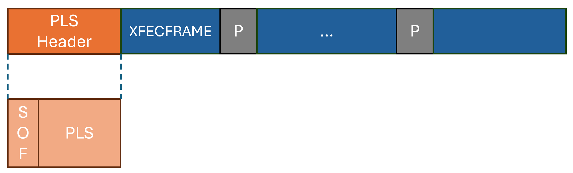
DVB-S2X inherits the fundamental Standard Frame Structure from DVB-S2, as shown in
Figure 1, which consists of a Physical Layer Header (PLHEADER) followed by an XFECFRAME [
1].
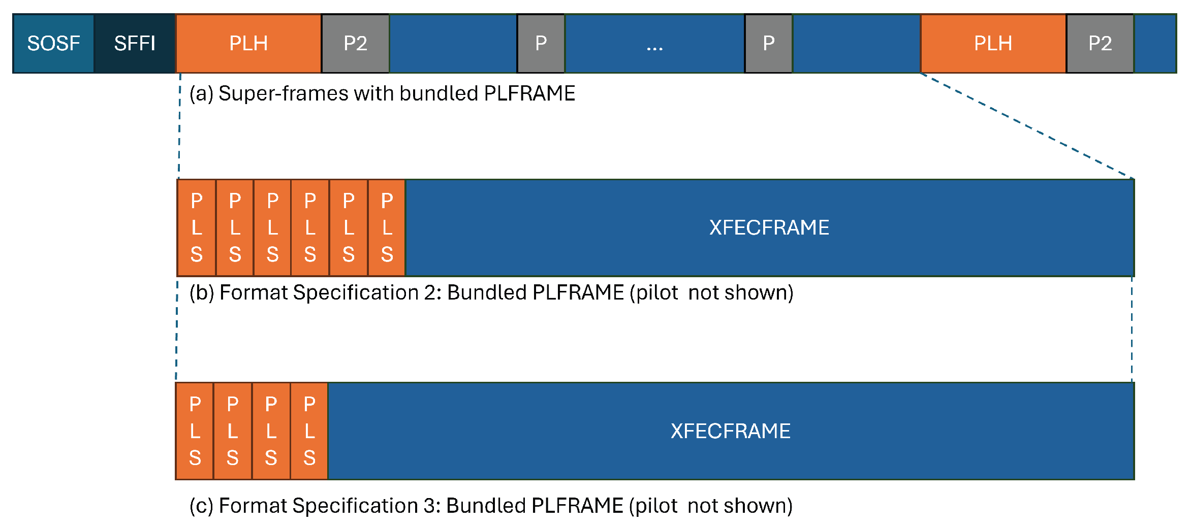
In addition, to support advanced satellite applications such as Beam Hopping and Precoding, DVB-S2X defines advanced Super-Frame architectures in Annex E of the standard, specifically including Format 2 and Format 3 structures, as illustrated in
Figure 2 [
1].
These advanced formats introduce the concept of Bundled PLFRAMEs, allowing multiple PLFRAMEs to be integrated into a single transmission unit to enhance scheduling flexibility. It is worth noting that the Physical Layer Signaling (PLS) block plays a critical role in both the standard architecture and the Super-Frame. In the standard single frame, the PLS is transmitted only once; whereas in the Super-Frame architectures designed for high robustness (Format 2 and Format 3), the system employs PLS block repetition mechanisms of 6 and 4 times, respectively [
1].
Consequently, as evidenced by the structural differences shown in the figures, developing a technique capable of rapidly parsing these heterogeneous structures, accurately performing PLS detection, and identifying the MODCOD is crucial for DVB-S2X receivers. This capability not only ensures synchronization stability but also significantly reduces processing latency when switching between different architectures.
2.2. PLS Field Structure
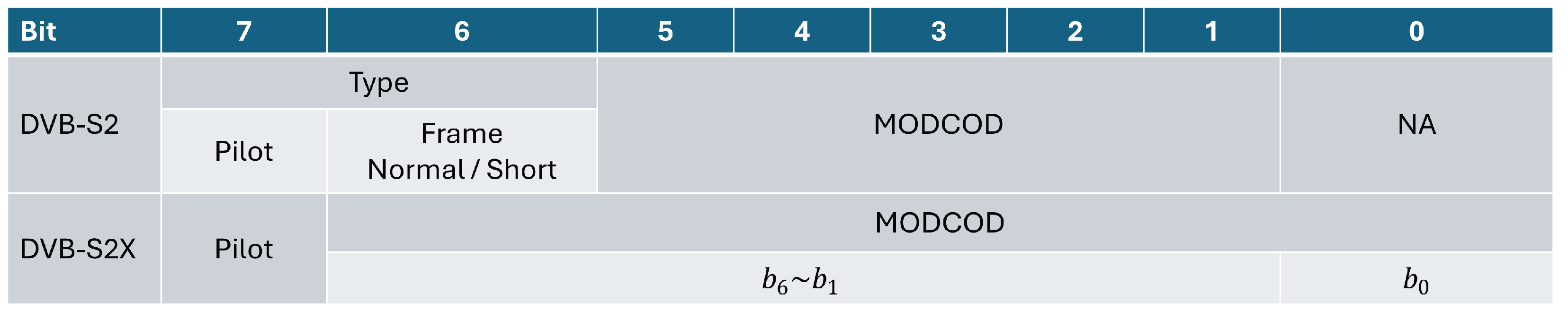
The bit definition of the PLS field in DVB-S2X differs from previous standards, as shown in
Figure 3. Therefore, this section re-analyzes the generation mechanism of the PLS Code to examine its characteristics.
As can be seen from the figure, the legacy DVB-S2 uses to distinguish between normal and short frames, with MODCOD occupying only 5 bits (∼). In contrast, to support finer granularity in spectral efficiency, DVB-S2X removes the independent frame length indicator, integrating it to expand the MODCOD field to 7 bits (∼), where is the key bit corresponding to the new entry in the generation matrix. It is worth noting that is retained as the Pilot indicator in both generations.
In the PLS Code generation process, a new generation matrix
G is adopted as shown in Equation (
1).
To accommodate the newly added , a row vector is added to the matrix, producing a codeword which remains 32 bits in length.To facilitate understanding of the relationship between the new and legacy architectures, we define as the sub-generation matrix corresponding to ∼, which generates a base codeword . In this architecture, the mechanism of functions similarly to a scrambling layer: when , the first row of the generation matrix is ignored, and the codeword is determined by ; when , the base codeword undergoes an exclusive OR operation with (i.e., ). As for , its corresponding vector is an all-one vector, implying that solely determines whether the polarity of the final output is inverted.
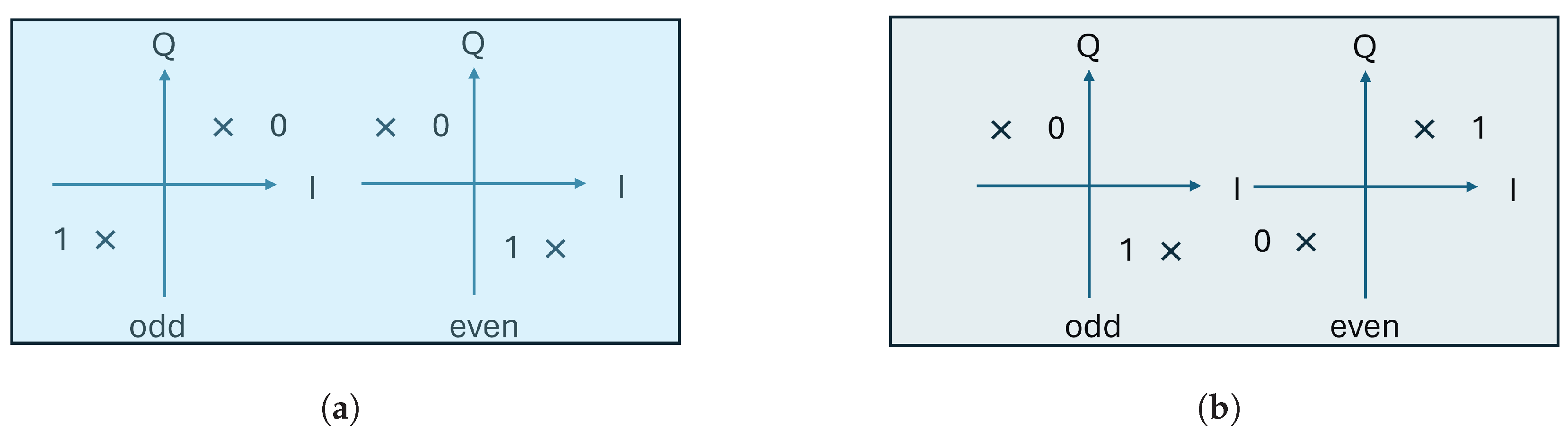
In addition, the mapping differences of the
-BPSK constellation between the legacy and new versions are illustrated in
Figure 4. Specifically, the choice of constellation points depends on the parity of the symbol index and the setting of
. For odd index symbols: in the legacy mode (
), the mapping points are
; whereas in the DVB-S2X mode (
), the mapping points are changed to
. For even index symbols: when
, the mapping points are
; however, when
, they correspond to
. This demonstrates that in addition to coding differences, DVB-S2X introduces specific phase rotations via
at the modulation layer.
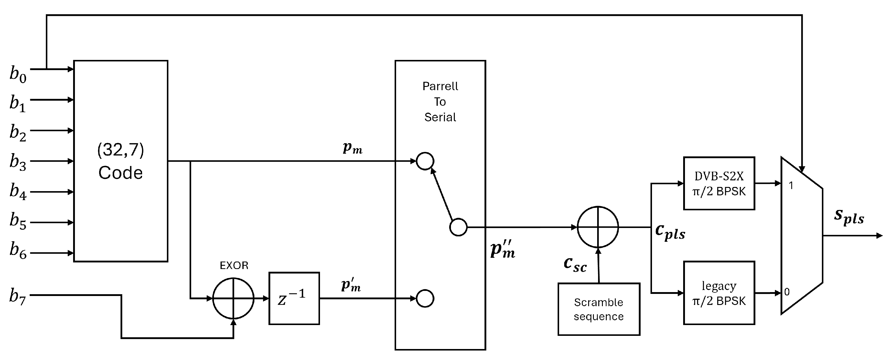
The generation flow of the DVB-S2X PLS field is illustrated in
Figure 5.
The input information first passes through a (32, 7) encoder to produce a 32-bit base codeword , a step that corresponds to the operation of the generation matrix G described previously. Subsequently, the codeword undergoes Parallel-to-Serial conversion and performs modulo-2 addition with a predefined scramble sequence to whiten the spectrum. Finally, the processed sequence is mapped onto the -BPSK constellation corresponding to the specific , forming the transmitted PLS physical layer signaling signal and denote it as .
2.3. Signal Representation
To facilitate the design of the frame synchronization algorithm—specifically, we reformulate the generation process of the PLS symbol. Instead of viewing it solely as a sequence of bitwise XOR operations, we model the process as phase rotations in the complex plane.
We define the set of unknown parameters to be estimated as
. In this proposed model, all binary data bits are mapped to phase vectors on the unit circle. Specifically, the control bits
and
are defined as the following phase terms:
Similarly, the Walsh code , derived from bits ∼, and the sequence , determined by , are mapped to their respective phase sequences and .
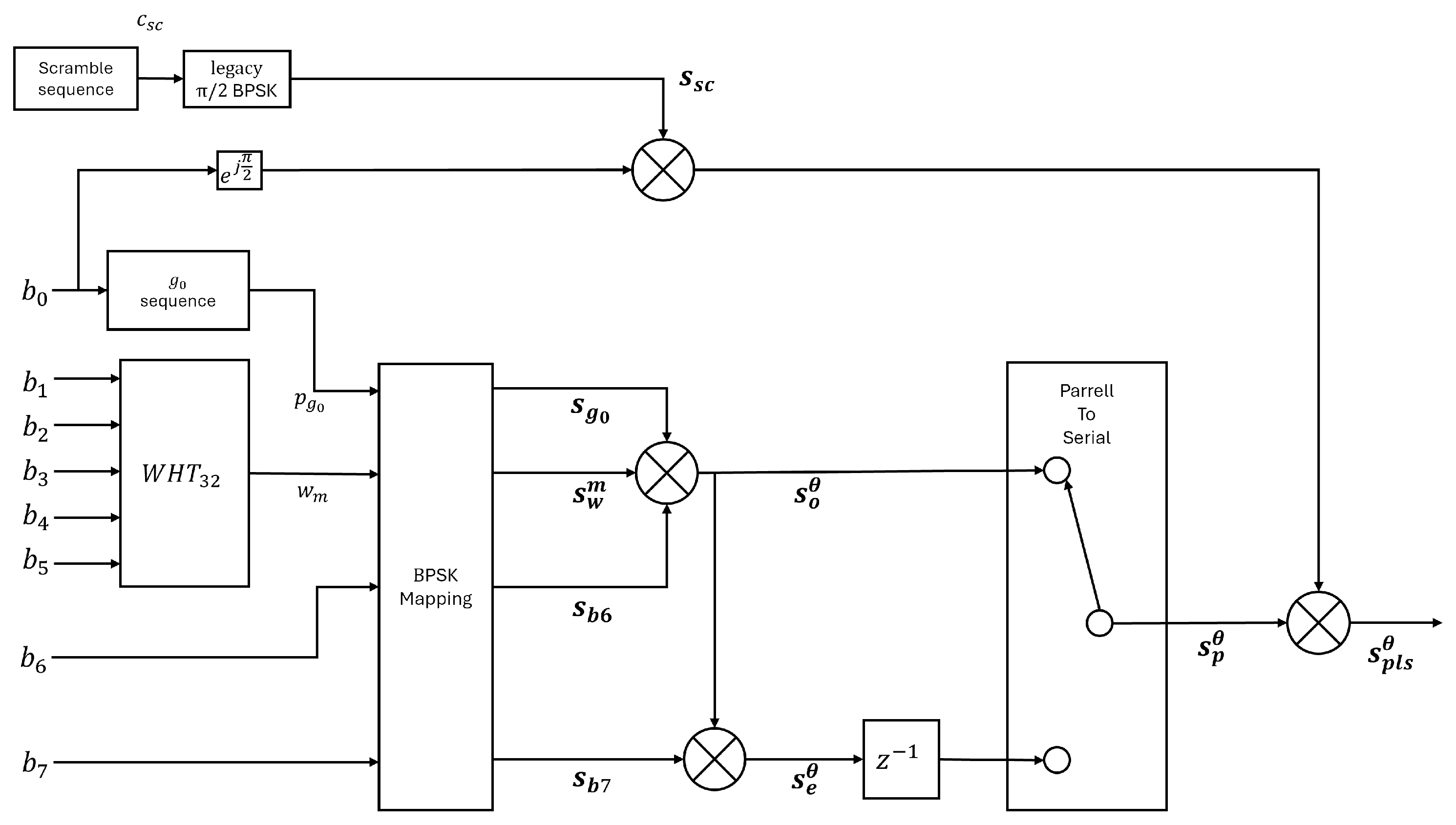
Figure 6 illustrates the improved hardware generation architecture based on this phase-decoupled concept. As depicted, the architecture explicitly decouples the signal generation into two distinct paths. The upper path is responsible for generating the reference phase signal,
. Governed by the scrambling sequence
and the indicator bit
, this path determines the fundamental BPSK mapping rule, dynamically selecting between the Legacy and DVB-S2X operational modes.
In parallel, the lower path generates the data modulation term,
, which encapsulates the parameter set
. Within this branch, the odd-indexed symbol
is modeled as the base Walsh code phase
, rotated by the phase offsets of
and
, as expressed by:
Subsequently, the even-indexed symbol
is derived from the odd symbol by superimposing an additional phase rotation determined by
:
Finally, the transmitted PLS symbol,
, is obtained as the product of these two phase components:
This mathematical model effectively decouples the unknown data parameters from the known scrambling sequence. This separation allows the receiver to remove the component and subsequently utilize the GLRT algorithm to efficiently search and match the parameters within .
2.4. Joint Detector Design
This section assumes that Carrier Frequency Offset and Symbol Timing Offset are calibrated, and the received symbols are denoted by .
2.4.1. System Model and Likelihood Function
While Carrier Frequency Offset is a critical issue for satellite receivers, the implementation of Doppler Pre-Compensation using satellite ephemeris and GNSS can substantially degrade its impact. As specified in 3GPP TS 38.101-5 [
11], the residual CFO is strictly bounded to within
ppm of the carrier frequency. Operating under this feasible low-CFO condition, we model the received signal over an Additive White Gaussian Noise channel. Assuming the receiver hypothesizes a frame timing offset
u within the observation window, the received discrete-time baseband signal
for the Physical Layer Signaling code is expressed as:
where
denotes the length of the PLS code;
represents the transmitted PLS symbol determined by the parameter set
; and
is the complex AWGN sample following a circular symmetric normal distribution
.
Since the noise samples are independent and identically distributed, the conditional probability density function for the received vector
given timing
u and parameters
is given by:
This likelihood function can be rewritten in vector notation as:
2.4.2. Optimal Detection Criterion
Based on the Maximum Likelihood Estimation principle, the optimal timing
and parameters
are obtained by maximizing the likelihood function (
8). Taking the natural logarithm and ignoring constant terms irrelevant to
, maximizing the likelihood is equivalent to minimizing the Euclidean distance in the exponent:
Expanding the squared term yields:
Since the received energy is independent of the hypothesis and the PLS code employs constant-envelope modulation, minimizing the distance is equivalent to maximizing the correlation.
We define the correlation function
as:
Thus, the optimal estimator is given by:
Since this estimator jointly estimates the frame timing
u and the parameter set
based on the maximum likelihood criterion, we denote this proposed scheme as the Joint Maximum Likelihood (JML) detector.
2.4.3. Expansion of the Correlation Function
Direct computation of the correlation for the full parameter set is computationally intensive. Therefore, we reformulate the correlation function to utilize efficient transforms. Assuming the correct timing index
is known, the PLS symbol
is decomposed into the scrambling sequence
and the antipodal modulated Walsh symbols
, such that
. Substituting this into (
11), we define the descrambled signal
as:
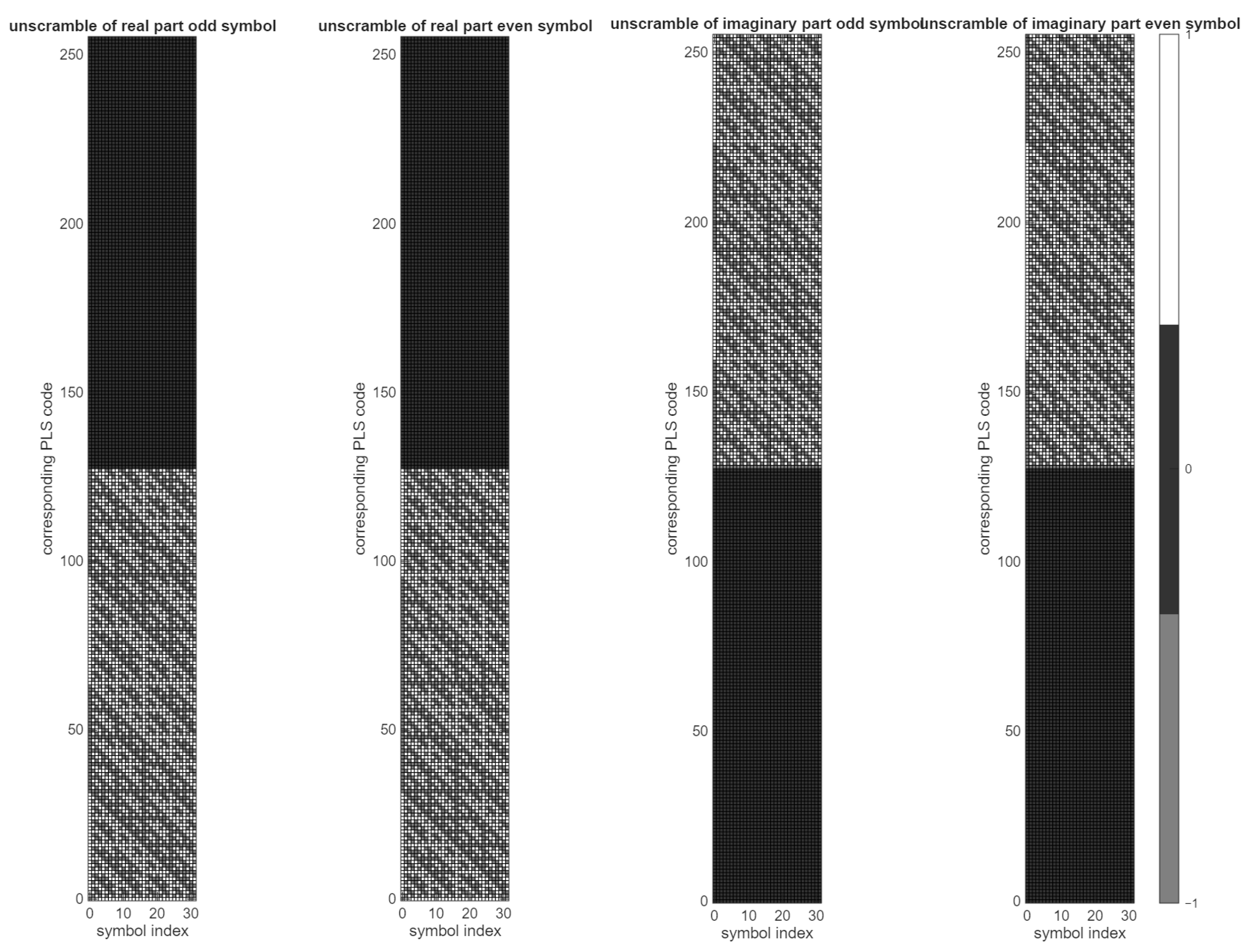
Figure 7 illustrates the constellation of the descrambled signal
.
The structure of
depends on the mode bit
, which directly affects
. To efficiently handle both legacy and DVB-S2X modes, we define a composite received signal denoted as
and
:
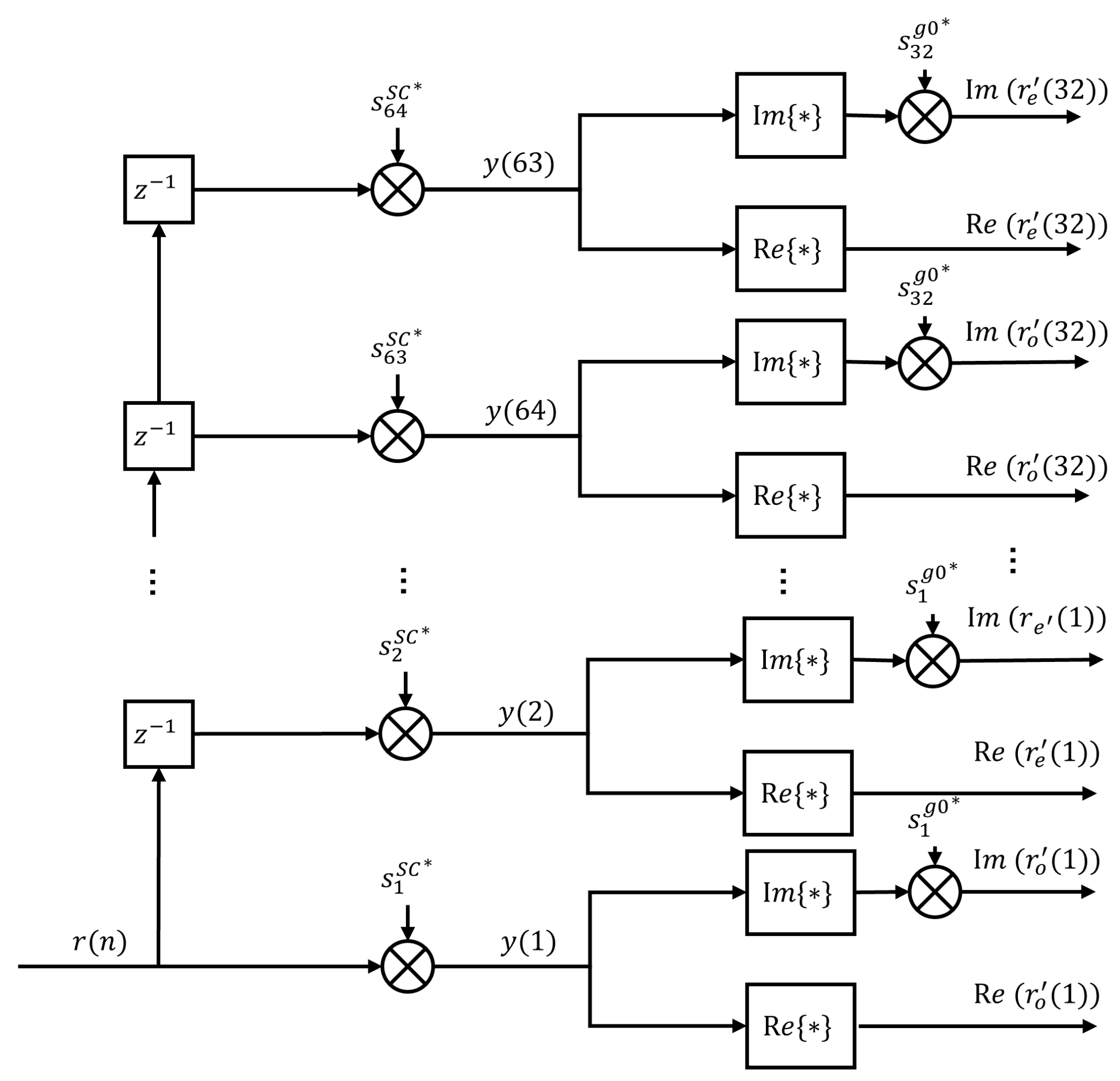
The
Figure 8 show the block diagram of the relationship form
to
.
We analyze the correlation metric expansion for the two cases of :
When
, the modulation follows the legacy mode where the symbols are projected onto the real axis:
When
, the modulation follows the DVB-S2X mode. This mode introduces an additional phase rotation of
relative to the legacy mode, along with the scrambling symbols
:
The correlation with the Walsh code
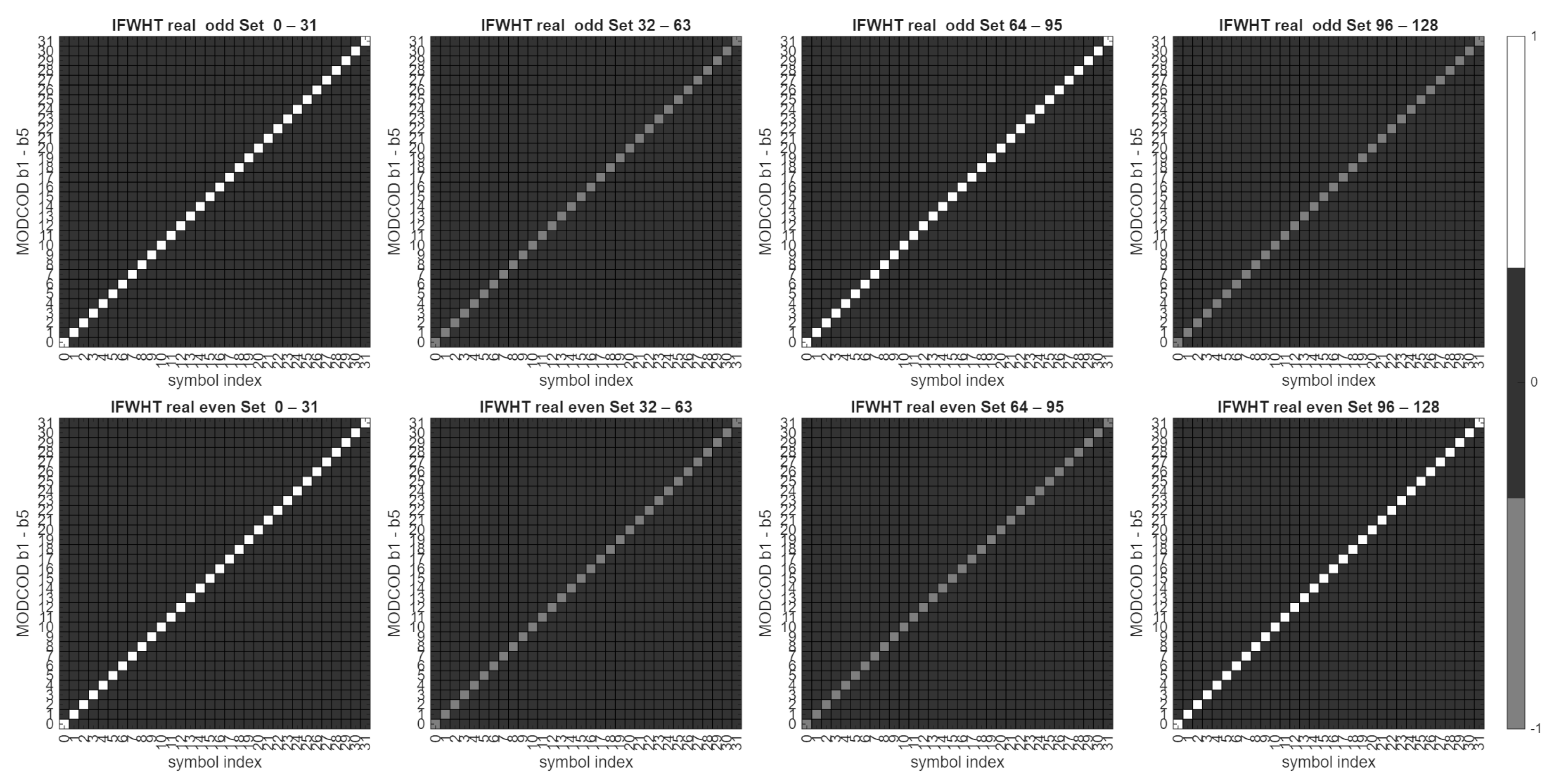
can be efficiently computed using the Inverse Fast Walsh–Hadamard Transform to reduce computational complexity:
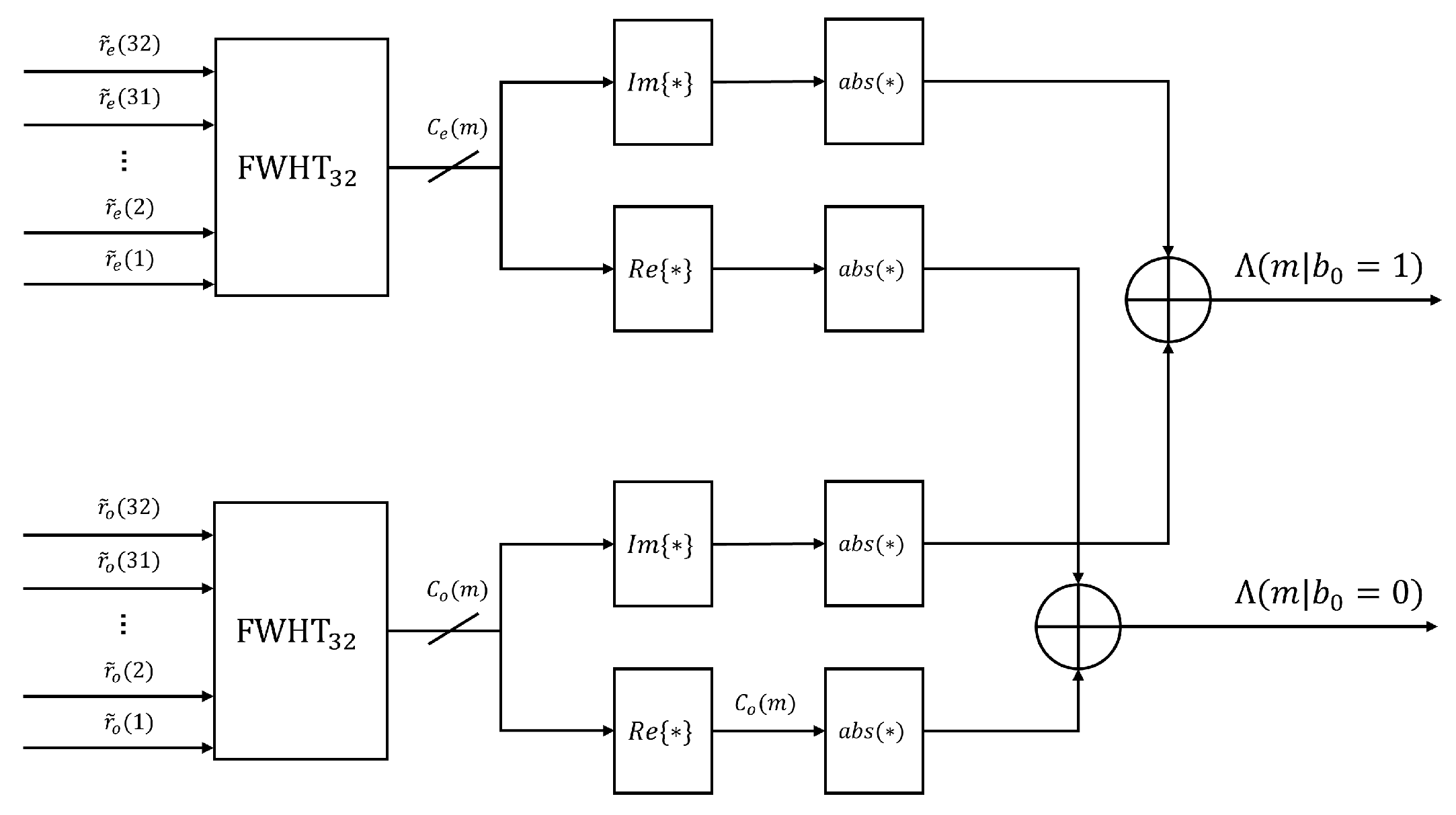
The block diagram of this transform is shown in
Figure 9.
The correlation can thus be expressed as:
To eliminate the dependency on unknown polarity bits, non-coherent combining is applied to yield the final decision metric
:
The optimal timing and parameter estimates are determined by maximizing this metric:
The flow of processing can be illustrated into
Figure 10.
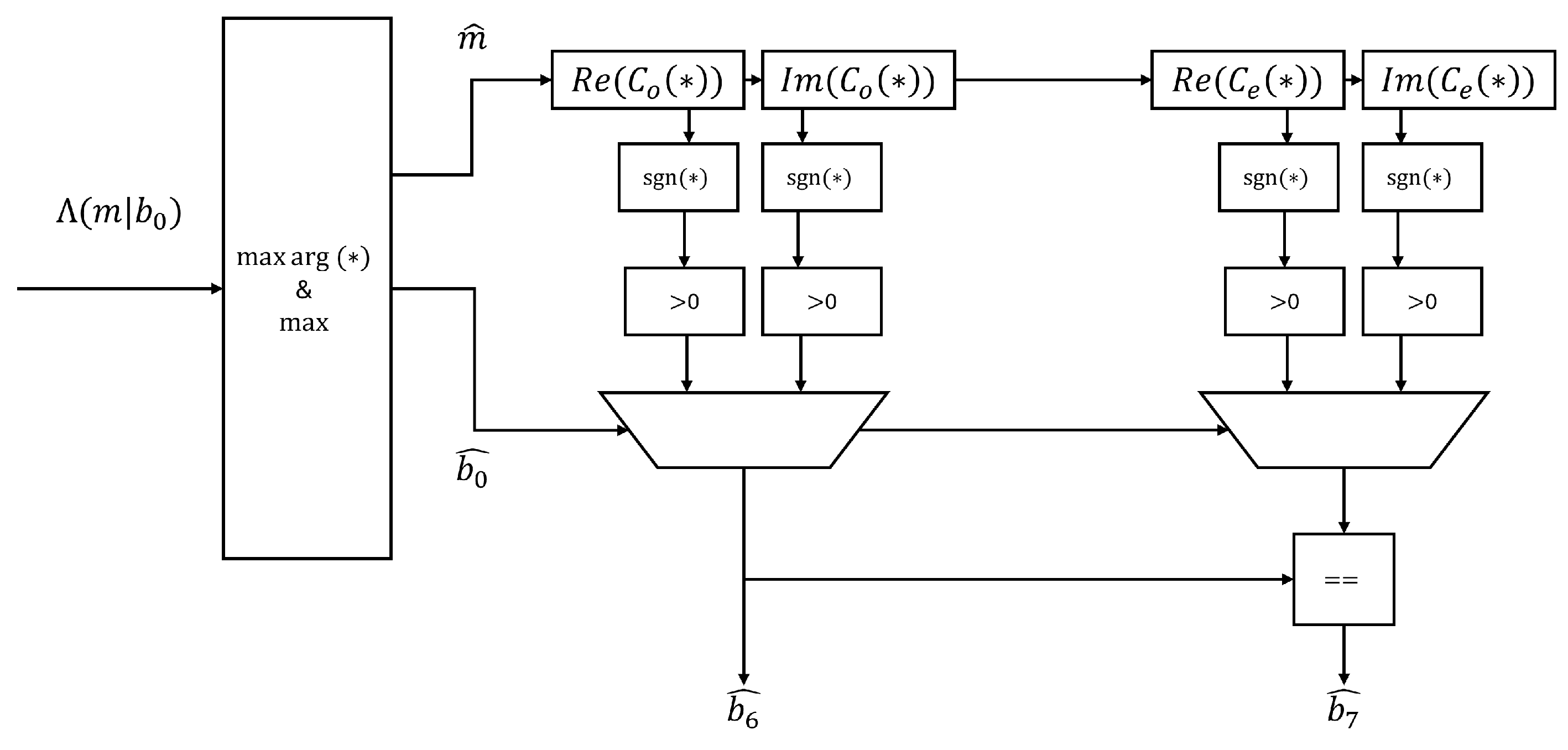
Finally, the decisions for
and
are derived from the sign of the correlation peaks:
The PLS Code Decision could be depicted into
Figure 11.
This architecture ensures optimal detection performance equivalent to the Maximum Likelihood criterion with significantly reduced computational complexity.
3. Result
The proposed architecture is implemented using a fully parallel design to ensure real-time processing capabilities. The primary resource consumption stems from the parallel FWHT blocks and the metric calculation units.
Table 1 presents a resource comparison between the proposed method, the brute-force correlation approach, and the differential detection scheme [
3].
3.1. Resource Utilization Analysis
To evaluate hardware efficiency, we analyzed the resource utilization of the proposed fully parallel architecture, targeting the number of logic adders and data-word registers. The processing pipeline comprises three stages: descrambling, FWHT, and decision. The descrambling stage utilizes 128 registers for input alignment and 192 adders for complex-valued sign inversions. The core FWHT module, implemented with four parallel engines each containing five pipeline stages, dominates resource consumption, requiring 640 registers and 640 adders. Including the final metric calculation and comparator tree, the total resource usage is approximately 1087 adders and 832 registers.
As summarized in
Table 1, the proposed architecture achieves complete PLS decoding using a multiplier-less design, effectively avoiding the usage of DSP Slices in hardware, effectively avoiding the hardware multipliers mandated by the differential detection scheme [
3]. Furthermore, compared to the brute-force approach which requires massive resources (∼16,128 adders and 16,384 registers) to store and match all code candidates, our method reduces the logic adder count by a factor of approximately 15 and significantly lowers memory requirements while maintaining the full decoding capability.
3.2. Simulation Results and Discussion
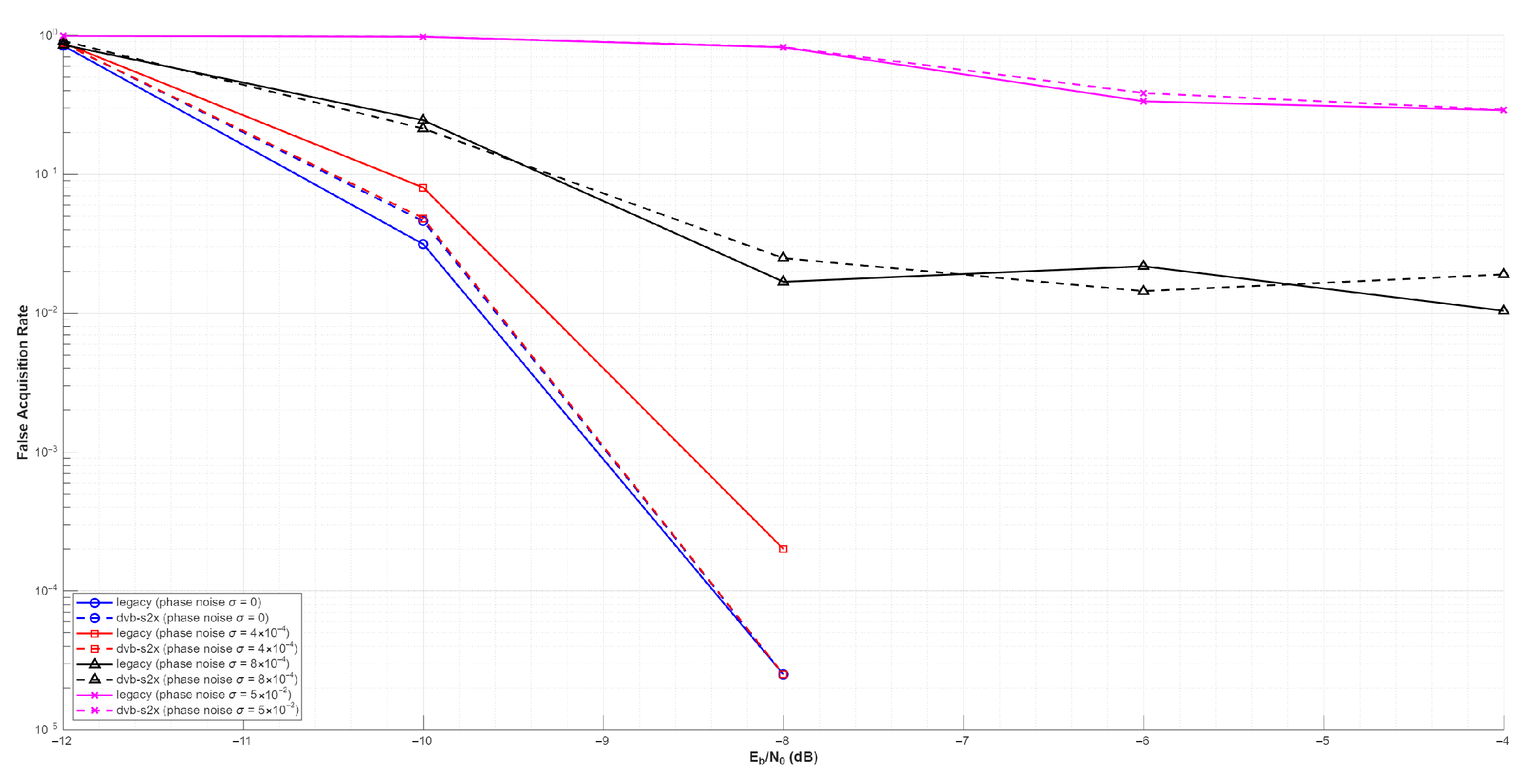
In satellite communication systems, phase noise from the local oscillator inevitably propagates into the baseband. To evaluate the performance of the proposed JML detector under realistic conditions, we modeled this impairment using a discrete-time Wiener phase noise process and analyzed its behavior across varying phase noise levels.
As shown in
Figure 12, when the phase noise standard deviation is
rad/symbol, the accumulated RMS phase drift over the 64-symbol PLS observation window is approximately
. According to recent studies [
12], BPSK-based communication systems can tolerate an RMS phase jitter of up to
without severe degradation. Since our accumulated drift is well below this theoretical threshold, the detection performance closely tracks the ideal AWGN bound. However, when
increases beyond this level (e.g.,
), the excessive accumulated phase drift disrupts the coherent integration over the long sequence, resulting in the expected emergence of an error floor in the high SNR regime. These simulation results are highly consistent with the theoretical expectations in [
12].
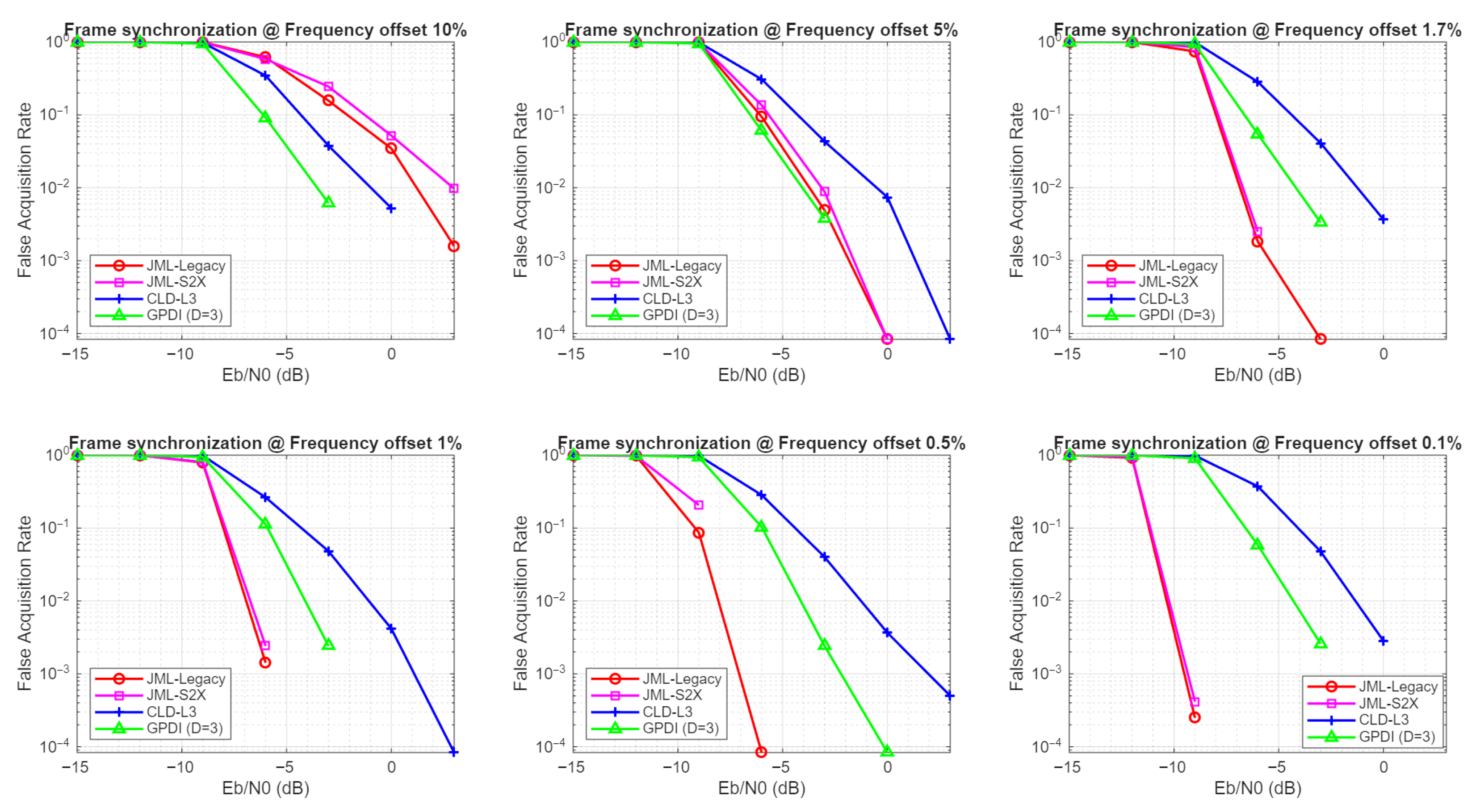
To evaluate the detection performance of the proposed architecture, Monte Carlo simulations were conducted over an AWGN channel. The performance metric used is the False Acquisition Rate, defined as the probability that the detector declares synchronization at an incorrect timing instant. We compared the proposed Joint Maximum Likelihood detector supporting both Legacy and S2X modes against the conventional Choi and Lee Detector [
3] and Generalized PDI.
Figure 13 illustrates the FAR performance under various normalized Carrier Frequency Offsets, ranging from 0.1% to 10%.
It can be observed that the performance of the proposed coherent-based JML detector is sensitive to residual frequency errors. In the regime of low frequency offsets, e.g., 0.1% to 1.7%, which represents the typical operating condition after coarse frequency synchronization, the proposed JML method significantly outperforms the differential-based CLD and Generalized PDI. Specifically, at a target FAR of with a CFO of 1.7%, the proposed method achieves an SNR gain of approximately 6 dB compared to the CLD and approximately 3 dB to the GPDI. Furthermore, the performance curves of JML-Legacy and JML-S2X are nearly identical, validating the robustness of the proposed unified architecture across different standard modes.
When the CFO increases to 5% and 10%, the performance of the proposed method degrades rapidly due to the phase rotation accumulation within the correlation window. In contrast, the CLD and Generalized PDI demonstrates robustness against large frequency offsets, outperforming the JML in these high-CFO scenarios.
This result aligns with the system assumption stated in
Section 1, where the proposed fine synchronization algorithm is intended to operate after the carrier frequency offset has been mitigated to a strictly bounded range e.g., within
. Within this targeted range, the proposed architecture offers a superior detection probability and noise robustness.
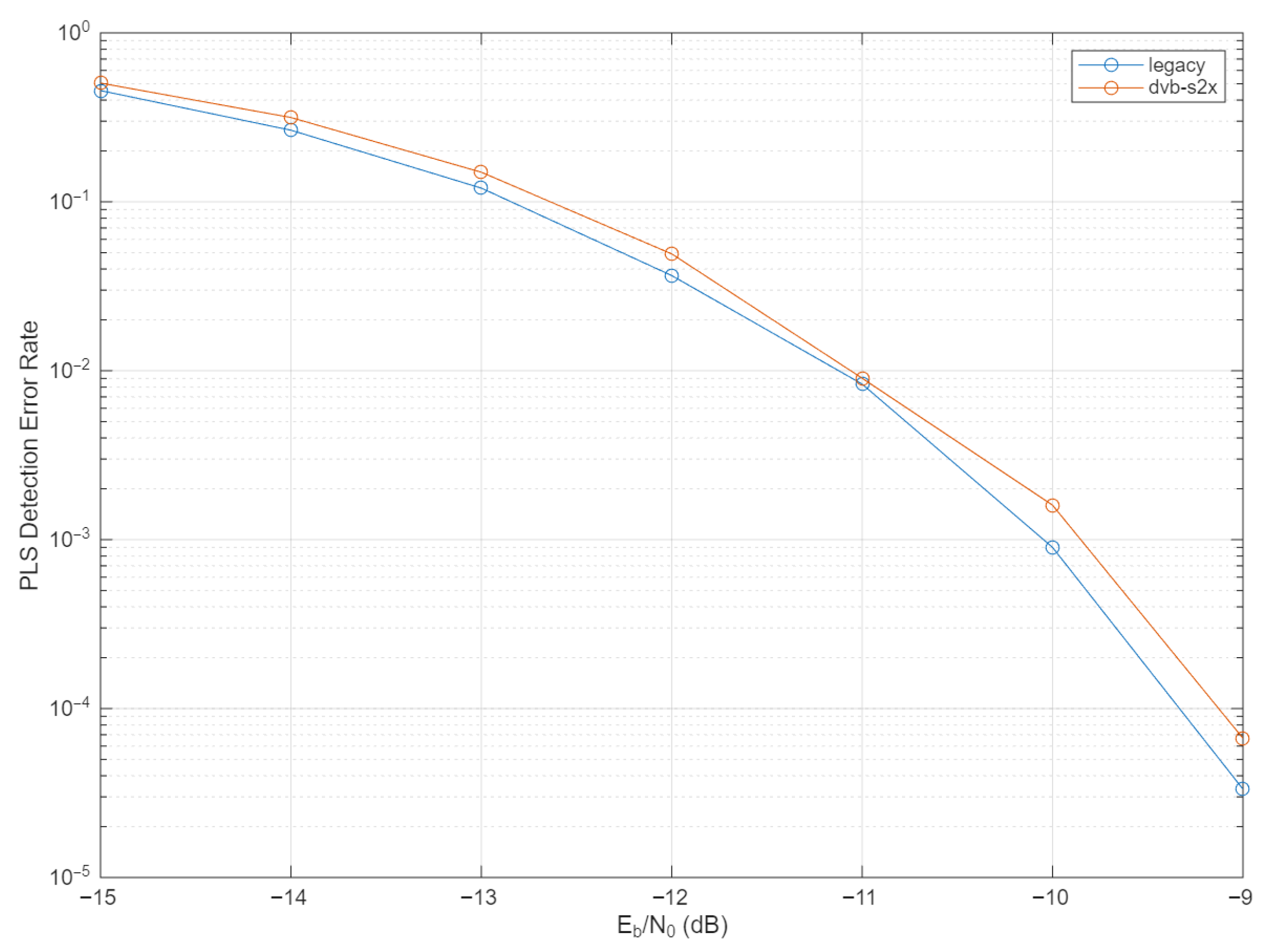
Following the synchronization performance analysis, we evaluated the decoding reliability of the proposed algorithm.
Figure 14 depicts the PLS Detection Error Rate performance against
assuming perfect synchronization.
The results demonstrate that the proposed architecture effectively identifies the PLS Code for both Legacy and DVB-S2X modes. As shown in the figure, the detection error rates for both modes exhibit a consistent waterfall characteristic, decreasing exponentially as the SNR increases. Notably, the DVB-S2X mode maintains a performance level highly comparable to the legacy mode, confirming that the introduction of the additional indicator and the expanded constellation mapping does not induce significant performance loss in the detection process.
4. Conclusions
This paper presents a universal joint frame synchronization and PLS decoding architecture tailored for the next-generation DVB-S2X satellite communication standard. By reformulating the PLS signal generation into a decoupled phase model and incorporating the Inverse Fast Walsh–Hadamard Transform, the proposed solution achieves detection performance equivalent to the Maximum Likelihood criterion while significantly reducing computational complexity.
Simulation results demonstrate that in the target operating regime of lower than frequency offsets, the proposed Joint Maximum Likelihood detector significantly outperforms conventional differential detection techniques, providing an SNR gain of approximately 6 dB at a false acquisition rate of . Furthermore, the architecture exhibits excellent robustness, supporting both Legacy DVB-S2 and DVB-S2X modes with consistent performance. Additionally, when applied to Super-Frame structures, the proposed JML detector can easily leverage PLS field repetition through metric accumulation, leading to even higher confidence in both PLS code identification and field location. Regarding hardware implementation, the design employs a fully parallel, multiplier-less structure. Compared to the brute-force approach, it reduces logic adder usage by a factor of approximately 15 times, thereby achieving high hardware efficiency.
In summary, the proposed architecture strikes an excellent balance between detection sensitivity, decoding reliability, and hardware cost, offering a promising solution for the synchronization design of high-performance DVB-S2X receivers.