Article

Active Vibration Control of a Servo-Driven Pneumatic Isolation Platform for Airborne Electromagnetic Detection Systems


1
School of Geophysics and Information Technology, China University of Geosciences (Beijing), Beijing 100083, China
2
Key Laboratory of Geo-Exploration Instrumentation of Ministry of Education, Jilin University, Changchun 130026, China
3
School of Mechanical and Electrical Engineering, China University of Mining and Technology, Xuzhou 221116, China
4
China Aero Geophysical Survey and Remote Sensing Center for Natural Resources, Beijing 100083, China
5
Key Laboratory of Airborne Geophysics and Remote Sensing Geology of Ministry of Nature Resources, Beijing 100083, China
6
Dipartimento di Scienze e Metodi dell’Ingegneria, Università degli Studi di Modena e Reggio Emilia, Via Amendola 2, 42122 Reggio Emilia, Italy
*
Authors to whom correspondence should be addressed.
Signals 2026, 7(2), 30; https://doi.org/10.3390/signals7020030
Submission received: 22 January 2026 / Revised: 10 March 2026 / Accepted: 17 March 2026 / Published: 1 April 2026
(This article belongs to the Special Issue Recent Development of Signal Detection and Processing)

Abstract

Airborne electromagnetic detection systems are highly susceptible to low-frequency motion-induced noise, which significantly degrades the extraction of weak geological signals. Conventional signal processing methods alone are often insufficient to suppress mechanically induced vibration noise, resulting in signal distortion and reduced detection reliability. To address this limitation, this study proposes an active noise suppression strategy that integrates mechanical vibration isolation with advanced signal processing. A pneumatic vibration isolation platform based on a cable-driven parallel robot (CDPR) architecture is developed to achieve precise orientation correction and effective vibration isolation. The system employs kinematic modeling and a servo-controlled pneumatic cylinder driven by a proportional directional valve to enable accurate dynamic regulation. Numerical simulations conducted in the Advanced Modeling and Simulation Environment (AMESim), combined with proportional–integral–derivative (PID) control, demonstrate that piston displacement overshoot is constrained within 0.2 mm. Furthermore, targeted filtering techniques are applied to enhance signal quality. Experimental results show that the response time for continuous step input is 0.18–0.2 s, with a steady-state error below 0.3 mm, confirming robust control performance. The proposed framework provides an effective low-noise solution for airborne electromagnetic detection and can improve survey reliability in deep resource exploration.

1. Introduction

Airborne Frequency-Domain Magnetotelluric (AFMAG) is an efficient, non-invasive geophysical exploration method widely used in several fields, such as mineral resource prospecting [1,2,3,4,5,6], hydrogeological investigations [7,8,9], oil and gas detection [10], ecological monitoring and disaster prevention [11,12,13], and engineering construction [14]. However, airborne electromagnetic detection systems are highly susceptible to environmental vibrations and mechanical noise during flight, particularly at low frequencies [15], as well as to small-amplitude vibrations that are difficult to eliminate effectively with traditional signal processing algorithms [16]. Related studies indicate that such noise primarily originates from engine vibrations, airflow disturbances, and the motion-coupling effects within the mechanical transmission components on the flight platform. The spectral characteristics of this noise significantly overlap with signals arising from variations in geological conductivity, which reduce inversion resolution and depth detection capabilities [17].
An analysis of the vibration transmission path reveals that environmental vibrations are transferred through mechanical structures to precision electromagnetic sensors [18], resulting in compounded noise. Although existing studies attempt to mitigate noise effects by enhancing signal processing algorithms—such as stationary wavelet denoising [19], wavelet threshold-exponential window fitting [20], and homomorphic filtering—these methods are essentially forms of “passive suppression” and cannot fundamentally address the interference of vibrational energy with sensitive detection equipment [21]. Therefore, in recent years, the international academic community has proposed an “active vibration isolation” approach that involves introducing high-performance isolation platforms between the vibration source and the sensors [22]. More specifically, such an approach combines mechanical design with closed-loop control strategies to achieve the isolation and attenuation of vibration energy at the source [23].
Within the field of active vibration isolation, various actuation mechanisms—including electromagnetic, hydraulic, and piezoelectric systems—have been investigated for vibration suppression. For instance, the Microgravity Active Vibration Isolation System (MAVIS) onboard the Chinese Space Station utilizes non-contact electromagnetic actuators. This system employs high-precision accelerometers to monitor the floater state in real time, leveraging electromagnetic forces to achieve micro-vibration suppression across six degrees of freedom (6-DOF) [24]. Similarly, research on maglev platforms demonstrates that universal vibration suppression for diverse payloads can be realized through redundant electromagnetic actuation combined with self-decoupling control strategies [25]. However, while electromagnetic actuators offer superior positioning accuracy, their inherent thermal radiation and electromagnetic interference (EMI) may adversely affect sensitive electromagnetic sensors.
With respect to hydraulic platforms, some researchers have proposed a novel active vibration isolation system for helicopters, in which hydraulic actuators are directly integrated into the support struts of the main gearbox to suppress vibration transmission [26]. In addition, a new type of magnetorheological fluid (MRF) damper has been developed to achieve broadband vibration isolation for engines, demonstrating significant isolation performance [27]. Although hydraulic systems can provide high force output, they are often associated with substantial weight, potential fluid leakage, and complex maintenance requirements. These drawbacks limit their suitability for weight-sensitive airborne applications.
To overcome these limitations, some researchers have developed active vibration isolation schemes based on piezoelectric stack inertial actuators to suppress multi-frequency discrete spectral vibrations in indoor substations [28]. Another study designed a hybrid active–passive vibration isolator utilizing piezoelectric ceramics to mitigate the effect of low-frequency vibrations on the positioning accuracy of high-precision equipment [29]. Piezoelectric actuators exhibit excellent performance in high-frequency vibration attenuation; however, their effectiveness diminishes substantially within the low-frequency regime, which characterizes typical airborne vibration spectra.
In contrast, pneumatic servo control systems are particularly well suited for suppressing low-frequency vibrations in airborne detection platforms, owing to their high dynamic response, low friction, lightweight structure, and robust environmental adaptability [30,31,32]. Among these systems, single-cylinder servo control serves as the core actuator of the pneumatic isolation platform, and its positioning accuracy and dynamic characteristics directly determine the overall performance of the isolation system [33]. However, traditional pneumatic systems are limited by nonlinear pneumatic stiffness, gas compressibility, and valve flow hysteresis effects, which make it challenging to achieve high-precision displacement control [34]. Wei et al. [35] demonstrated that the hysteresis characteristics of pneumatic proportional solenoid valves primarily stem from friction and air compressibility. Furthermore, in pneumatic servo polishing systems, precise control remains a significant challenge for traditional methods due to inherent nonlinearities such as cylinder friction and valve dead-zone effects [36].
Although sliding mode control (SMC) based on a high-gain observer (HGO) can enhance performance, its practical implementation in aerial exploration engineering remains constrained. By contrast, establishing a high-fidelity physical model for feedforward compensation of primary nonlinear factors, combined with PID control for high-precision displacement tracking, ensures both real-time response and system reliability within volatile flight environments. In recent years, with the rapid development of proportional directional valves, high-resolution displacement sensors, and embedded control algorithms, servo control technology based on multi-sensor fusion has further enabled new capabilities for the precise regulation of pneumatic isolation platforms [37].
Therefore, developing a lightweight, electromagnetically compatible, and high-precision active isolation strategy specifically tailored for ultra-low-frequency airborne vibrations is of substantial theoretical and engineering significance. In response to the global demand for ultra-low-frequency vibration suppression in airborne electromagnetic surveys, this study proposes the design of a pneumatic isolation platform based on single-cylinder servo control.
To clarify the research scope and ensure the feasibility of the proposed strategy, the following explicit assumptions are made: (1) the dominant environmental vibrations affecting the airborne platform are low-frequency (0–20 Hz) and small-amplitude; (2) the proportional directional valve exhibits a proportional and sufficiently stable dynamic response within the control voltage range of 0–10 V for controller design purposes; (3) the main interference sources (engine vibrations, airflow disturbances, and mechanical transmission coupling effects) are considered to be the primary, uncorrelated disturbances for the purpose of controller design and stability analysis; and (4) the laser displacement sensor provides measurement accuracy within its specified tolerance of ±0.03 mm, which is sufficient to support the closed-loop control requirements of this study. By establishing the platform’s kinematic and dynamic models and implementing high-precision servo control strategies via proportional directional valves, the system enables active pose correction and effective vibration isolation for airborne detection platforms. Additionally, a multi-sensor fusion algorithm is introduced to enhance the system’s robustness and interference resistance under complex operating conditions [38]. The present study ultimately aims to provide a highly reliable vibration isolation solution for deep resource exploration in airborne electromagnetic detection. It offers a scalable and adaptable approach to enhance data quality in global mineral exploration, environmental monitoring, and geohazard assessment, thereby supporting more accurate and efficient detection of strategic subsurface resources worldwide.
This study borrows the iterative and feedback-oriented idea of the CRISP-DM framework to organize the overall workflow, including problem definition, system design, modeling, simulation, experimental validation, and performance evaluation [39].

2. Pneumatic Vibration Isolation Platform

2.1. Design of Pneumatic Vibration Isolation Platform

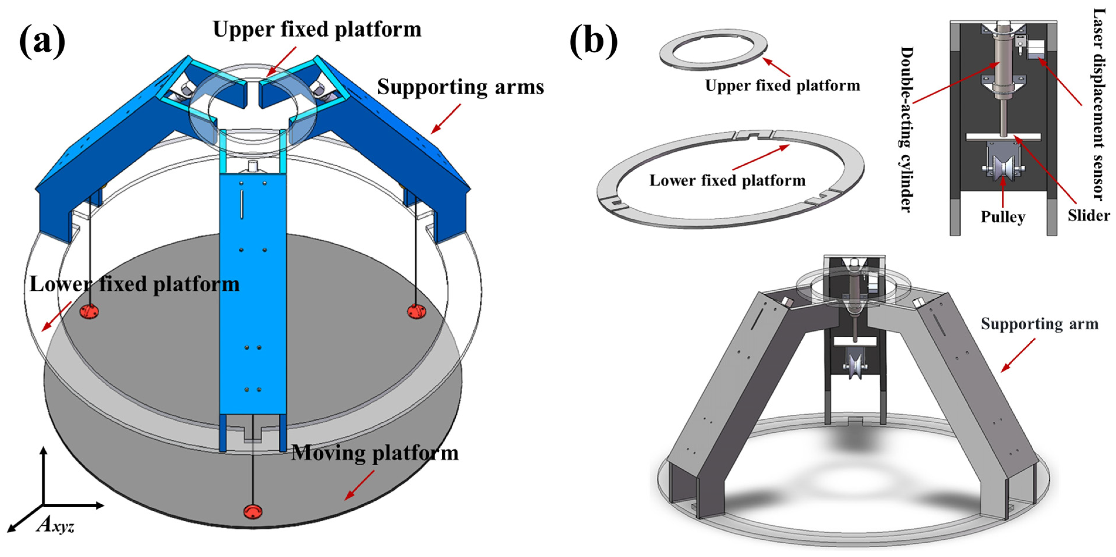
The pneumatic vibration isolation platform designed in this study is developed based on cable-driven parallel robots (CDPRs). CDPRs are special robotic mechanisms that use cables to manipulate end-effectors [40]. Compared to traditional parallel robots, they are lighter, enabling higher-speed motion and lower inertial forces. Due to the flexible and variable length of cables, cable-driven parallel robots offer a larger workspace compared to traditional parallel robots [41,42]. As shown in Figure 1a, the designed pneumatic vibration isolation platform consists of an upper fixed platform, a lower fixed platform, a moving platform, three supporting arms, and three integrated cylinders. The system is controlled by cables driven by three movable sliders distributed along the circumference.
Figure 1b presents a detailed schematic of Figure 1a. Annular grooves are arranged on the upper and lower fixed platforms of the pneumatic isolation structure to constrain the position of the supporting arms. Each supporting arm houses a cylinder that functions as a pneumatic actuator. The piston rod of each cylinder is mechanically connected to a movable slider, while a laser displacement sensor mounted on the side continuously monitors the piston displacement. The movable slider is linked to the moving platform via a flexible cable, which passes over a fixed pulley aligned with the cylinder stroke, converting the piston’s linear motion into platform movement. The three supporting arms are mechanically connected to the upper and lower platforms through side ribs, forming the complete aero-electromagnetic pneumatic isolation structure.

2.2. System Integration for Airborne Deployment

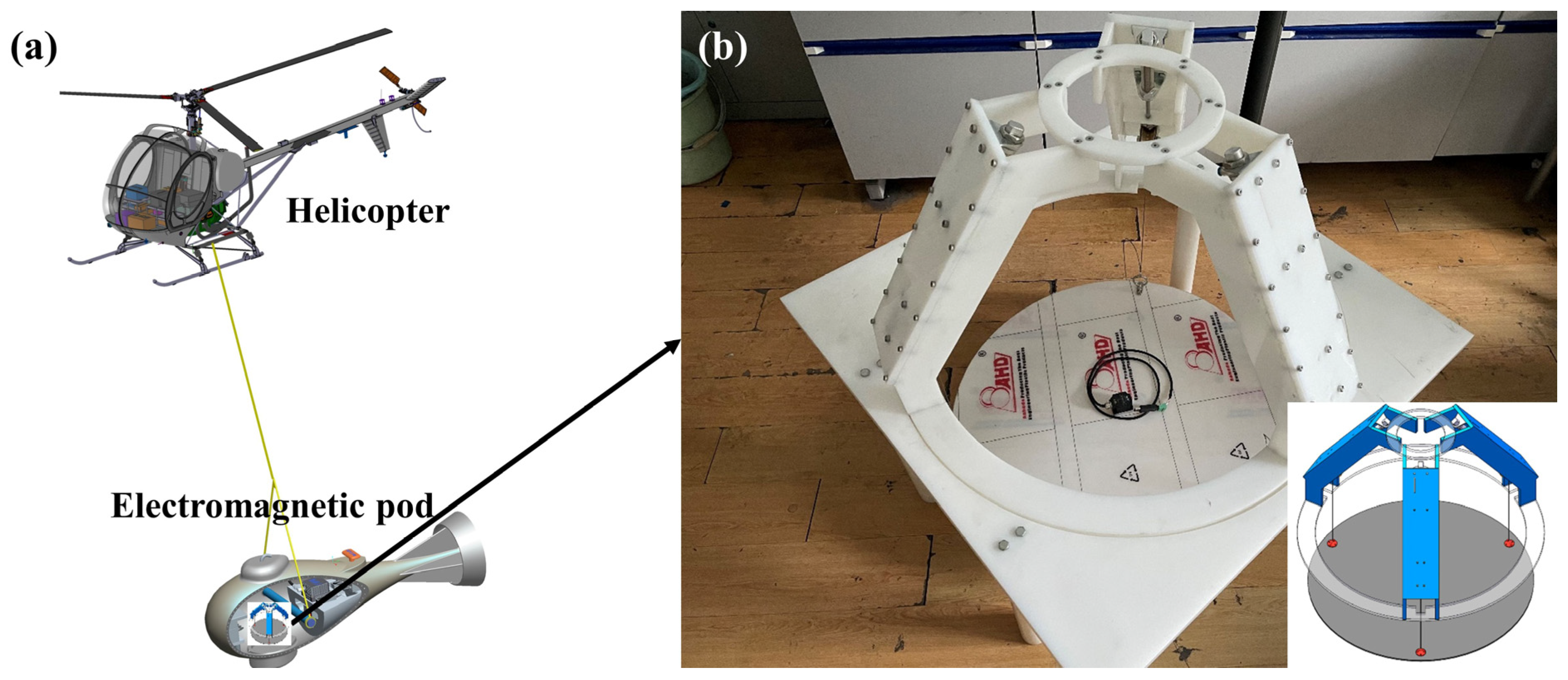
The proposed pneumatic vibration isolation platform is designed to be integrated into an airborne electromagnetic pod, which is typically suspended beneath a helicopter by a long towing cable (30–100 m in length). A schematic illustration of the full deployment configuration is provided in Figure 2a,b. During operation, the upper and lower fixed platforms of the isolation system are rigidly bolted to the internal load-bearing frame of the pod. The highly sensitive electromagnetic sensors (e.g., induction coils or electric dipoles) are mounted on the central moving platform. As the pod experiences coupled disturbances from airflow turbulence, cable swing, and helicopter-induced vibrations during flight, the platform actively adjusts the extension/retraction of the three pneumatic cylinders to counteract these external excitations in real time, thereby maintaining sensor stability.

2.3. Kinematic Model of the Pneumatic Vibration Isolation Structure

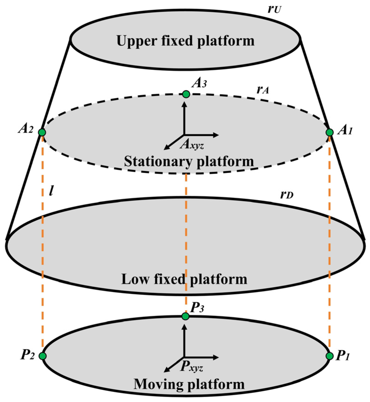
The pneumatic vibration isolation platform consists of a moving platform suspended by ropes attached to fixed points. To simulate and control its motion precisely, a kinematic model is established based on the platform’s geometry and structural characteristics. The key structural parameters are illustrated in Figure 3. In particular, the radius of the circumscribed circle of the moving platform is denoted r A , the radii of the upper and lower fixed platforms are r U and r D , respectively, and the rope length is L i .
Two coordinate systems are introduced:
  • The global coordinate system A x y z , fixed to the stationary platform.
  • The local coordinate system P x y z , fixed to the moving platform.
Let A i denote the global coordinates of the i-th rope attachment to the stationary frame and p i the local coordinates of the corresponding attachment on the moving platform. Then, the global coordinates of the moving platform attachment point are:
P i = T + R   p i
where T = [x y z]T is the translational displacement of the moving platform and R is the rotation matrix defining its orientation relative to the global frame.
The rope vector pointing from the moving platform attachment to the stationary attachment is
P i A i = A i P i = A i ( T + R p i )
and its length is
L i = P i A i
Intuitively, the rope vector indicates both the direction of the rope and its current length in space.
Figure 3. Schematic diagram of the pneumatic isolation platform. The moving platform is connected to the stationary frame via adjustable ropes.
Signals 07 00030 g003

2.3.1. Platform Orientation

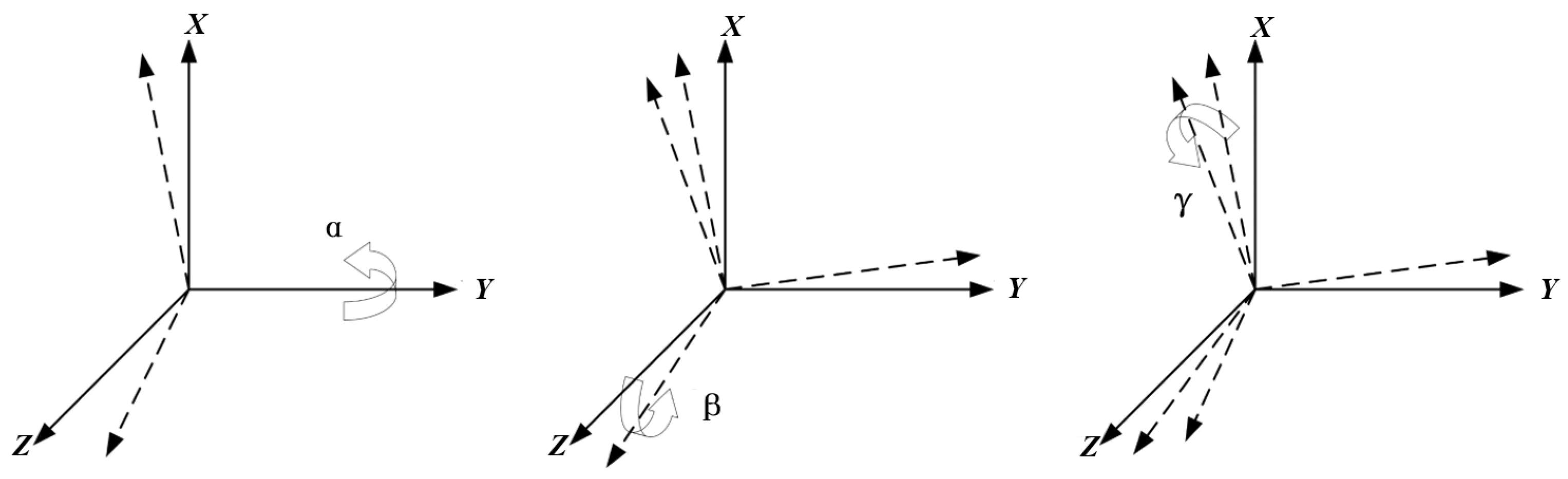
The moving platform’s orientation is represented using Z–X–Y Euler angles (heading α, pitch β, roll γ), as shown in Figure 4. The rotation matrix mapping vectors from the local frame P x y z to the global frame A x y z is obtained via successive rotations:
R = R Z α R X β R Y γ
with basic rotations
R Z α = cos α sin α 0 sin α cos α 0 0 0 1 ,   R X β = 1 0 0 0 cos β sin β 0 sin β cos β , R Y γ = cos γ 0 sin γ 0 1 0 sin γ 0 cos γ

2.3.2. Kinematic Inverse Solution

The platform state vector is defined as
Z = x y z α β γ T ,   Z ˙ = x ˙ y ˙ z ˙ α ˙ β ˙ γ ˙ T
The rope vector changes according to the motion of the moving platform:
P i A i = A ˙ i T + R p i P i A i ˙ = T ˙ R ˙ p i
For small rotations and quasistatic operation, the rotation derivative can be approximated using angular velocity:
R ˙ p i = ω × R p i ,   ω = [ α ˙ β ˙ γ ˙ ] T
The instantaneous rate of change in rope length is linearly related to platform velocity via the Jacobian:
L ˙ i = J i T Z ˙
where the Jacobian row for the i-th rope is
J i = [ u i r i × u i ]
where u i is the unit vector along the i-th rope, defined as
u i = P i A i P i A i
where P i A i = A i P i is the vector pointing from the moving platform attachment point P i to the fixed point A i , and r i × u i captures the rotational contribution to rope length change. When the platform rotates with angular velocity ω , the attachment point P i moves perpendicular to r i , and its component along the rope direction u i determines how the rope length changes. Stacking all J i gives the full Jacobian J , mapping generalized platform velocities to rope length rates. Finally, the rope acceleration is obtained by differentiating Equation (8):
L ¨ i = J ˙ i T Z ˙ + J i T Z ¨

2.3.3. Kinematic Forward Solution

To ensure the accuracy of the inverse kinematic solution, validation is performed through the forward kinematic model, which calculates the motion platform attitude based on the lengths of the supporting ropes. During attitude correction of the pneumatic vibration isolation platform, rope lengths vary dynamically, each corresponding to a specific instant and treated as a time-dependent variable. However, the rope length variation during platform attitude correction is nonlinear, making linear approximations insufficient for accurate real-time computation. Therefore, numerical compensation at each time step is required, along with error control within acceptable limits.
Forward kinematics determines the platform pose from known rope lengths. Let the functional relationship be
G Z , L = g 1 Z , L 1 g 2 Z , L 2 g 3 Z , L 3 = 0
where g i Z , L i measures the difference between the actual and target rope lengths. Differentiating with respect to L gives
d Z d L = 𝜕 G 𝜕 Z 1 𝜕 G 𝜕 L
To allow smooth interpolation during platform motion, we define a scaling parameter k [0, 1].
L ( k ) = L 0 + k ( L t L 0 )
which can be integrated numerically using Euler’s method:
Z n = Z n 1 + d Z n 1 d L n 1 k ( L t L 0 )
Nonlinearities can be handled efficiently using Newton–Raphson iterations:
Z n k = Z n ( k 1 ) ( 𝜕 G 𝜕 Z n ( k 1 ) ) 1 G ( Z n ( k 1 ) , L n )
with convergence defined by
G ( Z n , L n ) μ ,                       μ = 10 5
This value of μ = 1 0 5 is chosen to balance numerical accuracy with computational performance, in accordance with the resolution limits of the platform control system.
To implement and validate both the forward and inverse kinematic models, a simulation was conducted using MATLAB R2022b. First, the coordinates of the connection points between the stationary and moving platforms were defined, along with the initial pose of the moving platform. Then, target rope lengths were specified, and the corresponding platform attitude was calculated via the forward kinematic model. These results were used as input for the inverse kinematic solution, and the resulting rope lengths were compared to the initial target values to verify model consistency.
The kinematic models developed in this study form the theoretical foundation for the design and implementation of the control software governing the pneumatic vibration isolation system.

3. Modeling and Simulation of the Single-Cylinder Servo System

3.1. Design of the Single-Cylinder Servo System

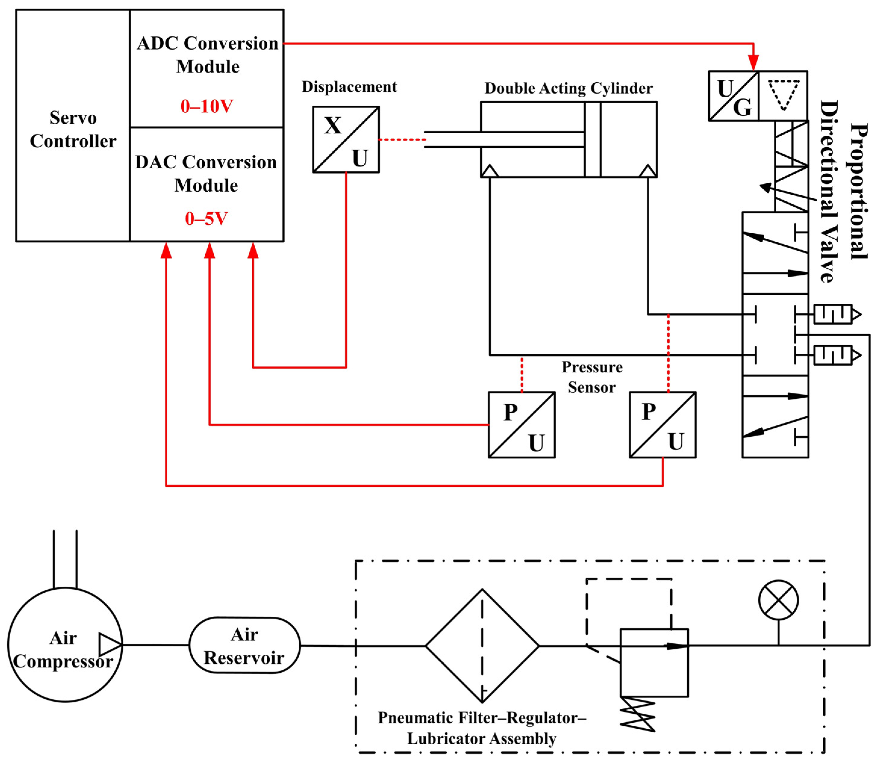
This paper focuses on a pneumatic vibration isolation structure that primarily tunes the piston positions of cylinders mounted on three supporting arms. Accordingly, the study emphasizes single-cylinder servo control as a basis for designing an active controller for the pneumatic isolation platform used in airborne geophysical exploration. An experimental platform for a proportional directional valve-controlled cylinder position servo system has been designed, as illustrated in Figure 5.
The single-cylinder position servo control system comprises an air compressor, pneumatic auxiliary components, an air reservoir, a proportional directional control valve, pressure sensors, a double-acting cylinder, a laser displacement sensor, and a servo controller. The system operates as follows: The air compressor supplies pressurized air, which is subsequently filtered and pressure-regulated by the pneumatic auxiliary components. Three pressure sensors, positioned upstream and downstream of the proportional directional control valve, are employed to detect the supply pressure and the gas pressures in both chambers of the double-acting cylinder. The servo controller’s analog-to-digital converter (ADC) module converts the displacement sensor’s analog voltage signal into a digital signal, which is subsequently compared with the target position. The flow direction and flow rate of the gas after passing through the proportional directional valve vary with the displacement of the valve spool. When an analog voltage of 0–10 V is applied to the proportional directional valve, the valve adjusts the spool’s movement direction according to the voltage level, thereby achieving servo control of the cylinder position.

3.2. Modeling and Simulation of the Proportional Directional Valve

AMESim (Advanced Modeling and Simulation Environment for performing Simulation of engineering systems, version 2021 R1) is an advanced simulation software with a graphical environment, featuring a rich library of models that allows for the rapid development of system models [43,44]. A model of the proportional directional valve MPYE-5-1/8-HF-010B is created for simulation, and the results are compared with sample curves to verify the accuracy of the constructed model.
The MPYE-5-1/8-HF-010B type three-position five-port proportional directional valve offers advantages such as good linearity and high dynamic performance. The bidirectional solenoid used in this valve has excellent dynamic characteristics, providing a high dynamic response frequency. Additionally, the valve’s spool displacement is driven by the solenoid’s magnetic circuit, eliminating the need for a spring return. As a result, this valve does not require an amplification circuit during use. Furthermore, the closed-loop control of the control unit includes the friction between the spool and the valve sleeve as well as the gas flow force, so these two parameters have minimal impact on the valve’s control performance. Based on its operating mechanism, the valve is modeled and parameterized using AMESim software’s mechanical library, signal library, control system library, and pneumatic component library [45].
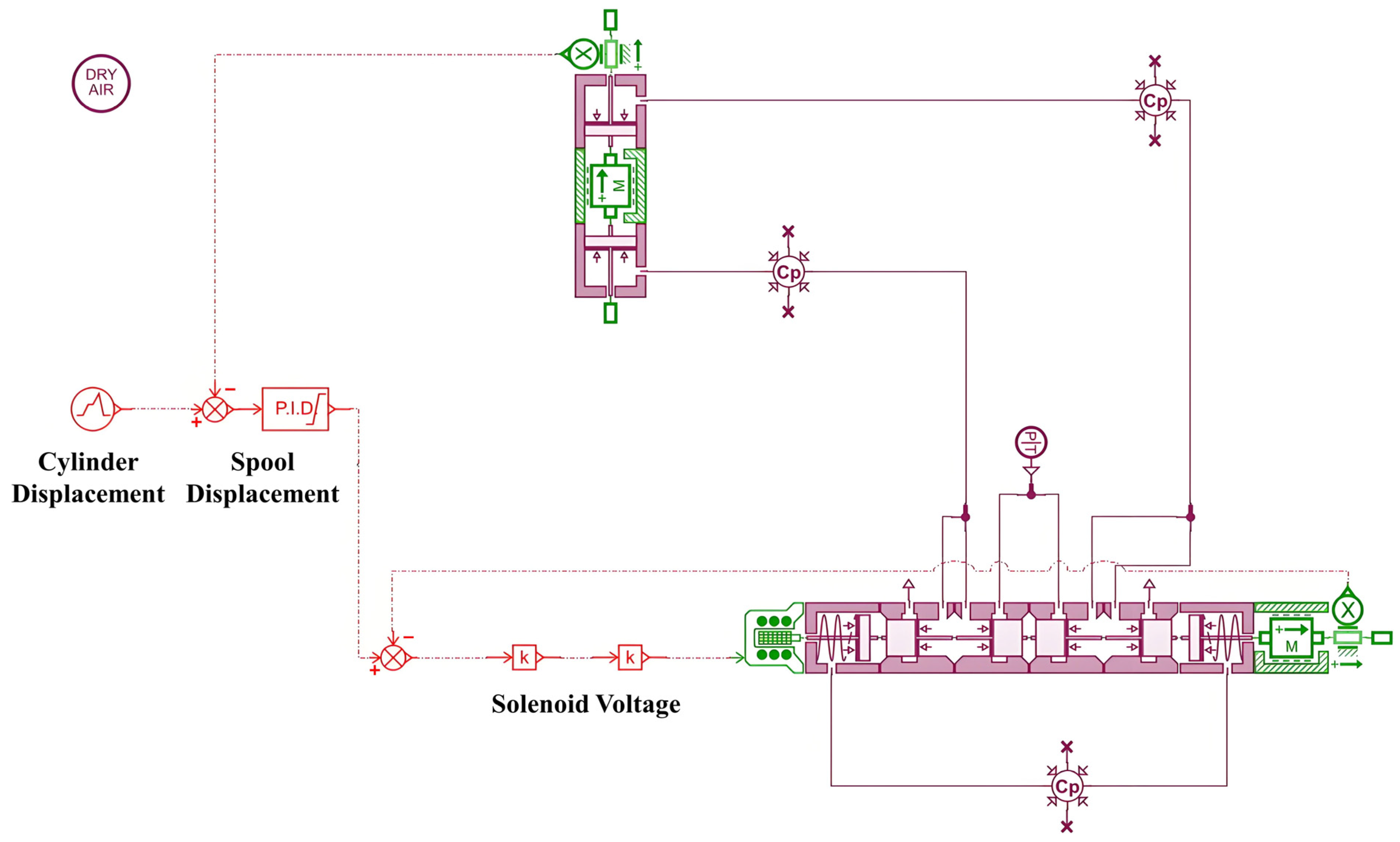
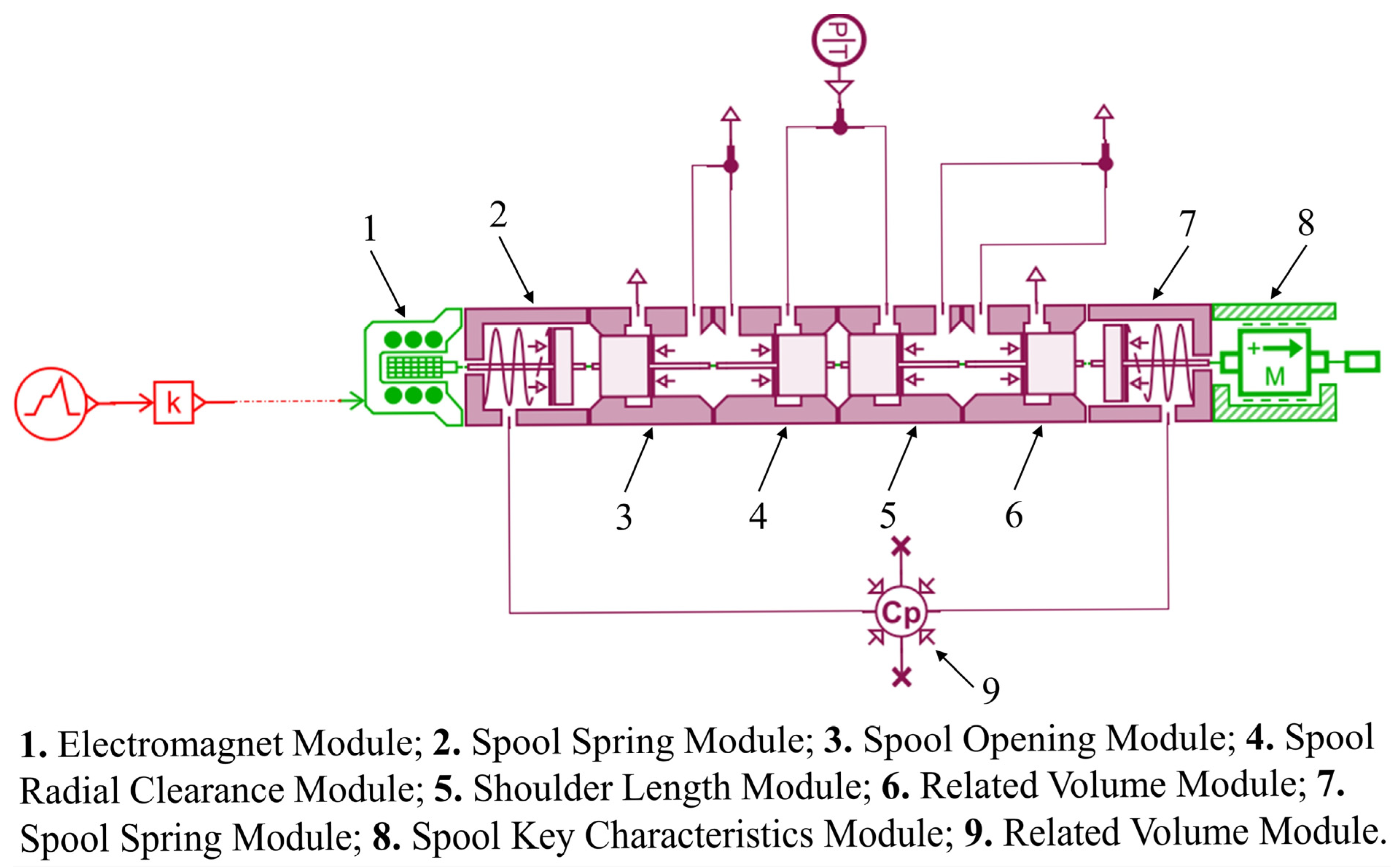
In the proportional directional valve model shown in Figure 6, Module 1 represents the solenoid, which generates the corresponding electromagnetic force based on the input voltage signal. Modules 2 and 7 represent the spool spring. Modules 3, 4, 5, 6, and 9 are used to simulate the opening of the spool throttling edge, the radial gap of the spool, and the length and volume between the spool shoulder. Module 8 represents the mass of the spool, Coulomb friction, viscous damping, and the travel range that the spool can move.

3.3. Modeling and Simulation of Pneumatic Servo Circuit

Based on the principle diagram of the single-cylinder servo system and the AMESim model of the MPYE-5-1/8-HF-010B proportional solenoid valve, a physical model of the single-cylinder servo system is established using the components from the AMESim software library, as shown in Figure 7. The key modules are: an electromagnetic force module (generates driving force according to input voltage), the valve core damping module (simulates viscous friction and Coulomb friction), and the throttle port module (controls gas flow rate), which jointly determine the dynamic response of the servo system. The main parameters of the cylinder are set as follows: piston diameter of 20 mm, cylinder stroke of 200 mm, total mass of the moving block of 1 kg, air source temperature of 297 K, and air source pressure of 0.3 MPa.
To further verify the performance of the selected PID control, a comparative analysis was conducted with alternative advanced controllers, whose results are shown in Table 1.
Although adaptive robust control and fuzzy PID control have better control accuracy and robustness, they suffer from high computational complexity and long debugging cycles, which are not suitable for airborne controllers with limited computing resources. The proposed PID control balances control performance and practical engineering implementation, fulfilling the requirements of airborne electromagnetic detection.
To verify the effectiveness of the single-cylinder servo system model, a closed-loop control study is conducted on the constructed model. The target value for the cylinder piston displacement is set, and the control signal for the proportional directional valve is set to 0–10 V. This control signal regulates the opening flow of the proportional directional valve, simulating the change process of the cylinder piston position.
As seen in Figure 8, with the combination of PID control [46,47], the maximum overshoot of the actual piston displacement is kept within 0.2 mm, which meets the precision requirements for aerospace electromagnetic pneumatic vibration isolation. This validates the correctness of the designed pneumatic servo system and confirms the feasibility of the proposed solution.

4. Pneumatic Position Servo Control Experiment

4.1. Experimental Platform Construction

The single-cylinder position servo control system consists of an air compressor, pneumatic auxiliary components, an air storage tank, a proportional directional control valve, a pressure sensor, a double-acting cylinder, a laser displacement sensor, and a servo controller. Key experimental setup details: (1) the supporting cantilever of the platform is assembled with PE high-density plastic, with a bolt preload of 8–10 N·m to ensure structural stiffness; (2) the coaxiality error between the laser displacement sensor and the cylinder is controlled within ≤0.1 mm to avoid measurement deviation; and (3) the sampling frequency of the data acquisition system is set to 100 Hz, which is determined based on the cylinder’s dynamic response characteristics (step response time ≤ 0.2 s) to ensure data integrity. To further verify the rationality of selecting PID control, a comparative analysis with advanced controllers is conducted, with the results shown in Table 2.
It can be seen that although adaptive robust control and fuzzy PID control have better control accuracy and robustness, they suffer from high computational complexity and long debugging cycles, which are not suitable for airborne controllers with limited computing resources. The proposed PID control balances control performance and engineering practicality, meeting the requirements of airborne electromagnetic detection.

4.2. Testing of Key Control Components

4.2.1. Proportional Directional Valve Spool Displacement Test

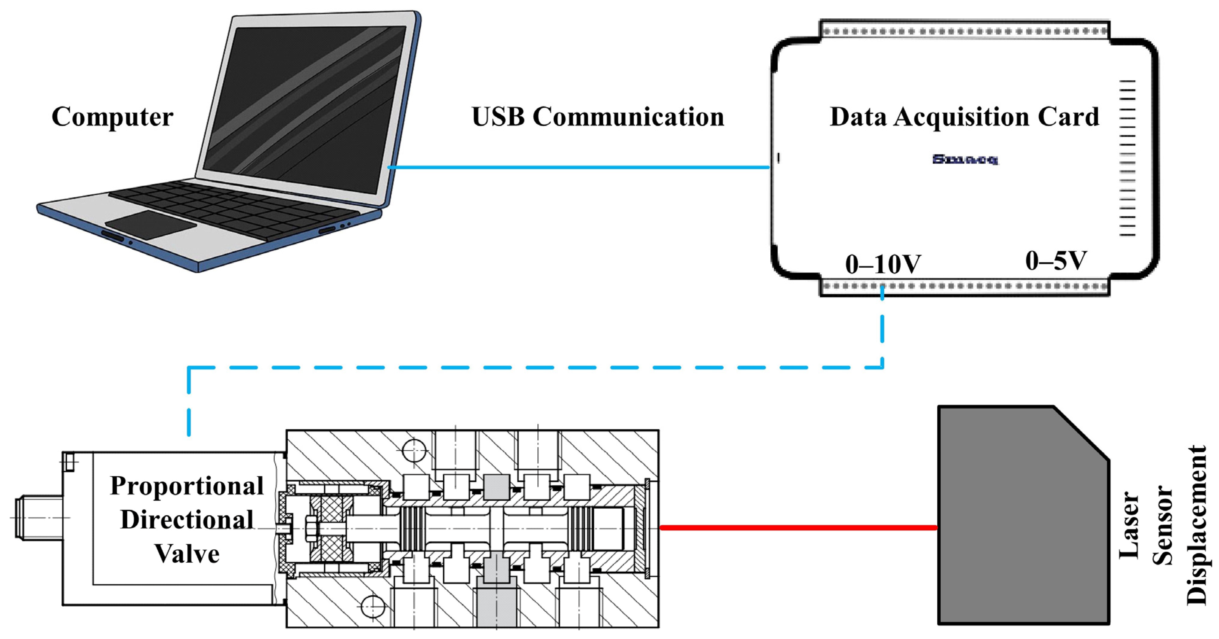
In the application of proportional directional valves, the displacement characteristics, i.e., the displacement of the spool varying with the control voltage, and the fact that this variation follows a proportional relationship, are crucial for precise control [48]. The principle of the test is shown in Figure 9.
First, the proportional directional control valve is fixed on the test bench to prevent external interference that might cause the valve to move during the experiment. Next, the position of the Panasonic HG-C1050 laser displacement sensor is adjusted to ensure the laser is aligned with the end of the spool of the proportional directional control valve. A data acquisition card, model USB3111 from Smacq, is used as the control element for the spool displacement test. The control voltage of the proportional directional control valve is adjusted through the Ao interface of this acquisition card, and the spool displacement data measured by the laser displacement sensor is recorded through the Di interface. This setup allows for precise experimental testing and analysis of the displacement characteristics of the proportional directional valve [49].
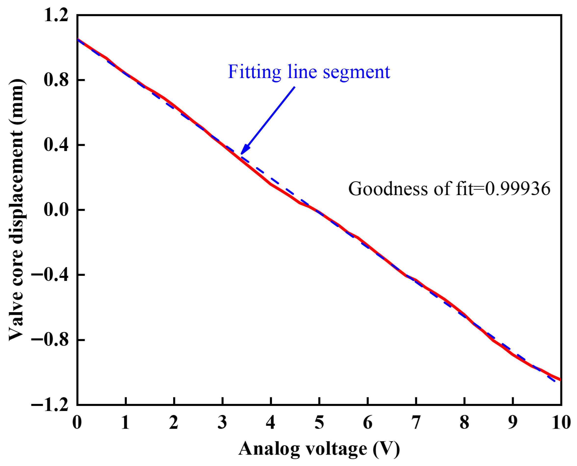
During the experimental test, the proportional directional valve, data acquisition card, and DC power supply are connected, and the laser displacement sensor is aligned with the spool of the proportional directional valve. The data acquisition card is used to apply a DC voltage signal ranging from 0 to 10 V, with a step size of 0.2 V, to the proportional directional control valve. The experimental results are shown in Figure 10. The displacement of the valve spool is approximately 2.1 mm, and there is a proportional relationship between the spool displacement and the voltage signal, exhibiting a certain linear pattern.

4.2.2. Valve Port Area Test of Proportional Directional Valve

By applying different voltages to the proportional directional valve, the spool displacement can be controlled, which, in turn, alters the valve port area and the gas flow output, achieving control over the cylinder’s movement direction, provided that the supply air pressure remains constant. Unlike the test results for the proportional directional valve spool displacement, the port area does not exhibit a linear relationship with the simulated voltage, and due to its unique structure, it cannot be directly measured by any instrument. Li et al. [31], through measurement and analysis of the spool’s motion state, derived the mathematical relationship between the spool displacement and the valve port area, as shown in Formula (17):
A = q v 0.124 P u T 1 273
In the formula, A represents the effective area of the valve opening, P u is the supply air pressure of the proportional directional valve, T 1 is the supply air temperature of the proportional directional valve, and q v is the volumetric flow rate of the gas entering the proportional directional valve.
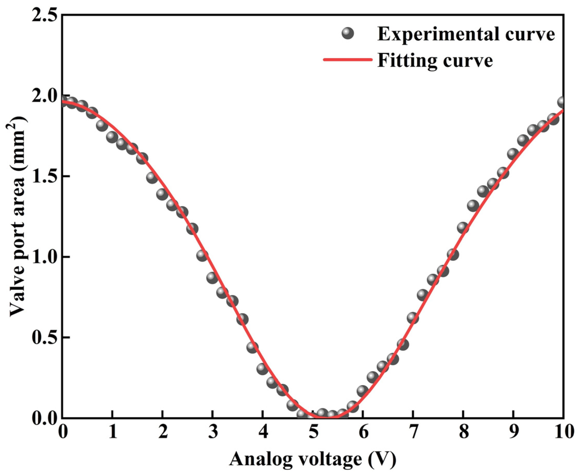
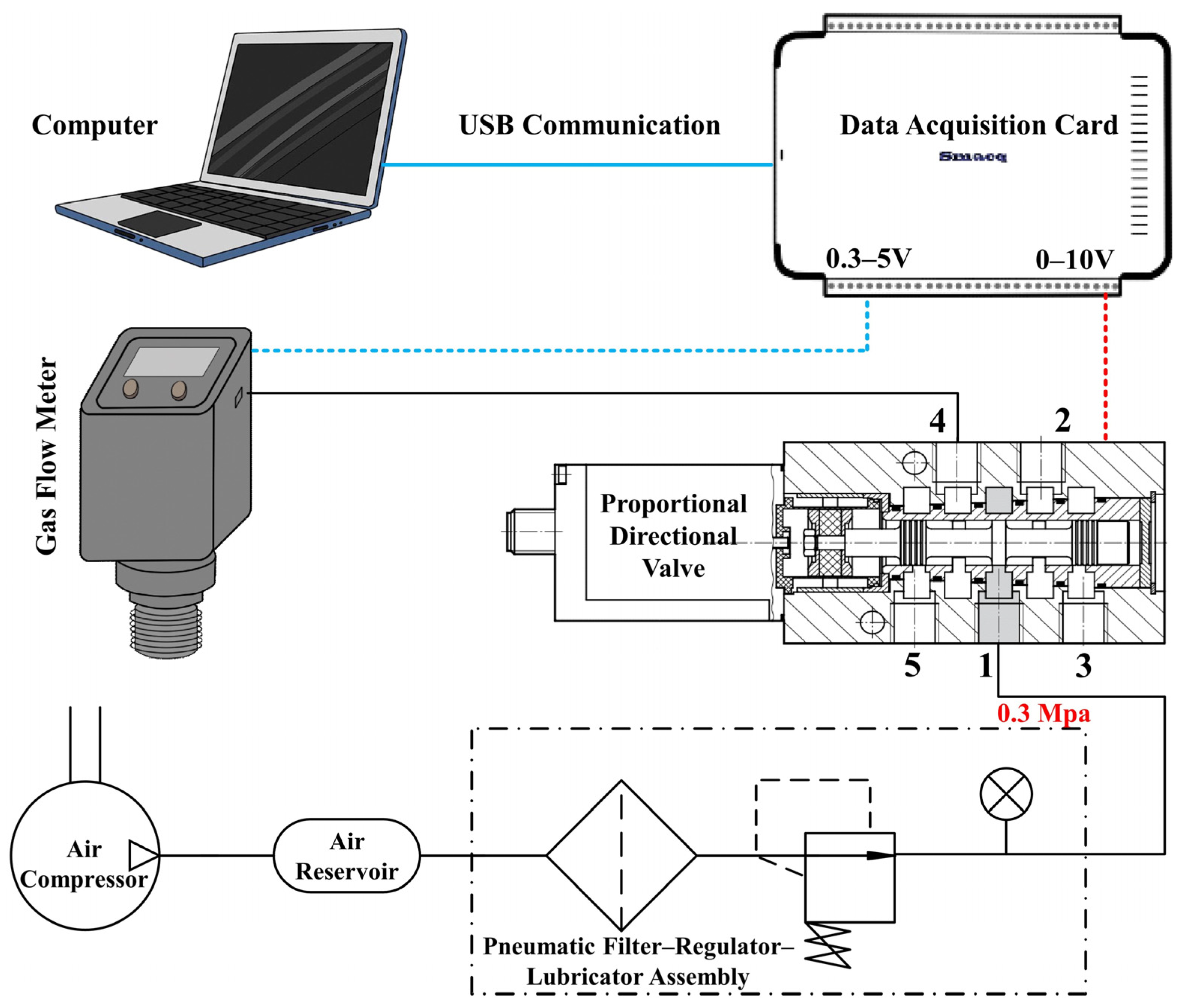
According to Equation (17), by measuring the volumetric gas flow rate passing through the valve opening, the valve port area can be calculated. The principle for measuring the gas volumetric flow rate is shown in Figure 11. The upstream gas pressure at the valve port is set to 0.3 MPa, and the gas source enters the proportional directional valve through port 1. The simulated voltage is applied with a step size of 0.2 V, ranging from 0 V to 10 V. A flow sensor is connected at port 4 of the valve to measure the real-time flow rate. The experiment is repeated, and the average value is taken.
Using the data acquisition card to collect data and substitute it into calculations, the simulated voltage and valve port area data are then imported into MATLAB. Based on the data trend, a combination of trigonometric functions and mathematical polynomials is selected as the functional relationship for the fitting function. Through multiple iterations, the mathematical relationship between the simulated voltage and valve port area is obtained, as shown in Figure 12.
The mathematical relationship between the effective opening area of Valve Orifice 1 and the control voltage is given by (18):
A u = 0.9627 sin 0.6145 U v + 1.448 + 0.06371 sin 1.467 U v 2.895 + 1.023  

4.3. Single-Cylinder Continuous Step Experiment

4.3.1. Single-Cylinder Servo Controller Design

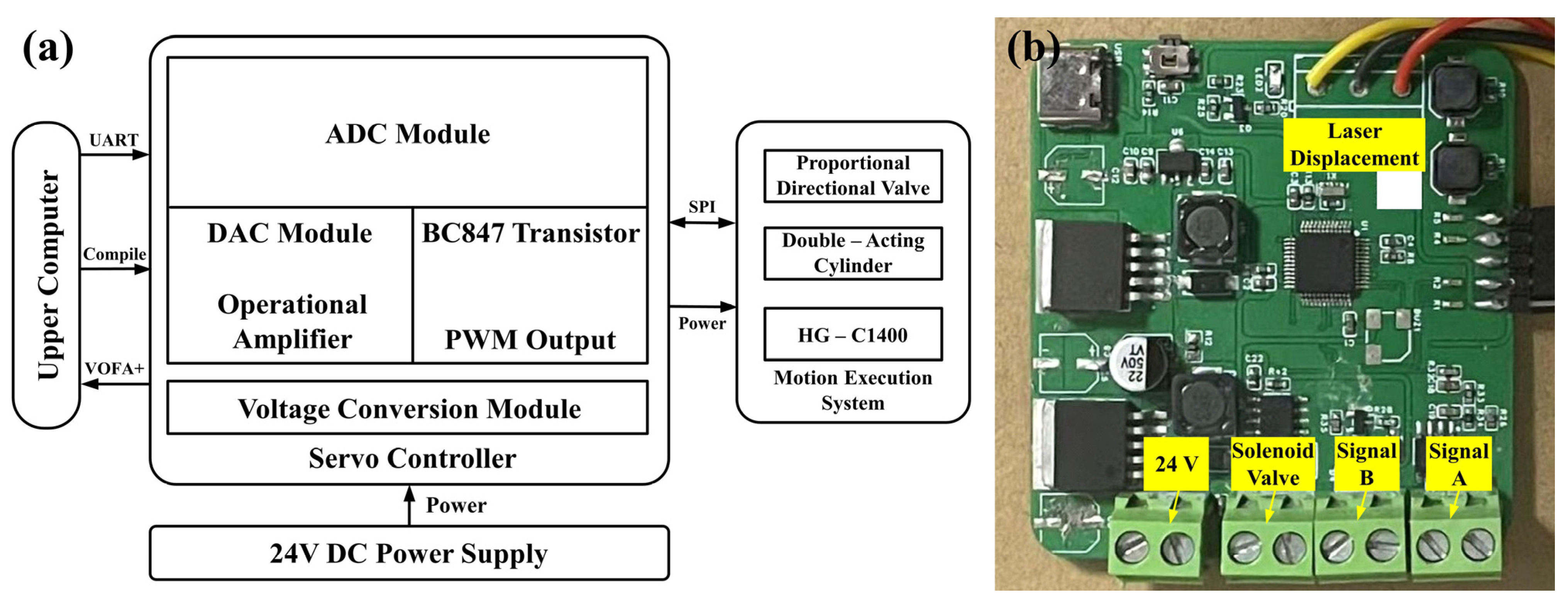
The single-cylinder servo system studied in this paper mainly consists of a proportional directional valve, cylinder, displacement sensor, and pressure sensor. In order to achieve cylinder position control, data acquisition of displacement and pressure sensors, and implementation of the control algorithm, the pneumatic servo controller functional board required for this experiment is shown in Figure 13. The designed servo controller needs to include a voltage conversion circuit to provide DC power to different components. In addition, the servo controller must also include an analog-to-digital conversion circuit and a digital-to-analog conversion circuit to ensure data interaction between the displacement sensor, pressure sensor, and proportional directional valve. Finally, to enable the servo controller to perform the required functions, it must have the capability for code compilation and writing. Based on the above analysis, the STM32F103CBT6 chip model is selected as the core processor for the embedded pneumatic servo controller in this experiment.

4.3.2. Experimental Methods

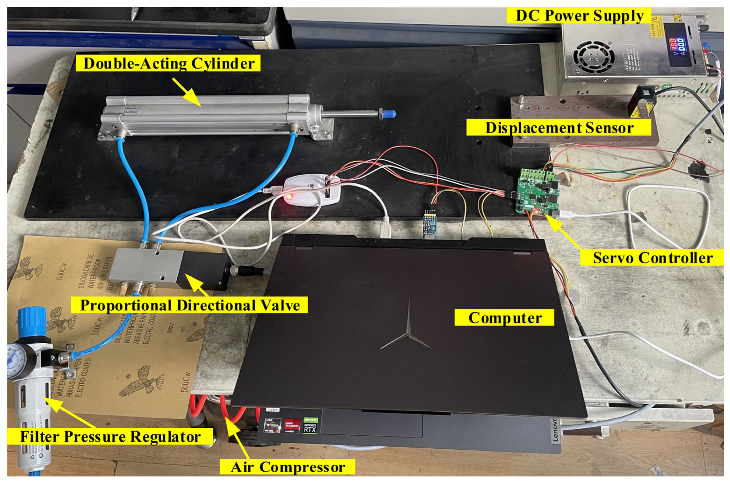
According to the pneumatic circuit connection of the single-cylinder servo control, as shown in Figure 4, and based on the pin configuration mentioned earlier, the laser displacement sensor and proportional directional valve are installed on the corresponding interfaces of the single-cylinder servo controller. The 24 V DC power supply is connected to the power supply circuit of the single-cylinder servo controller, completing the conversion of 12 V and 5 V voltages, thereby powering the components on the experimental platform. The final setup is the single-cylinder continuous step response test platform, as shown in Figure 14.

4.3.3. Experimental Results

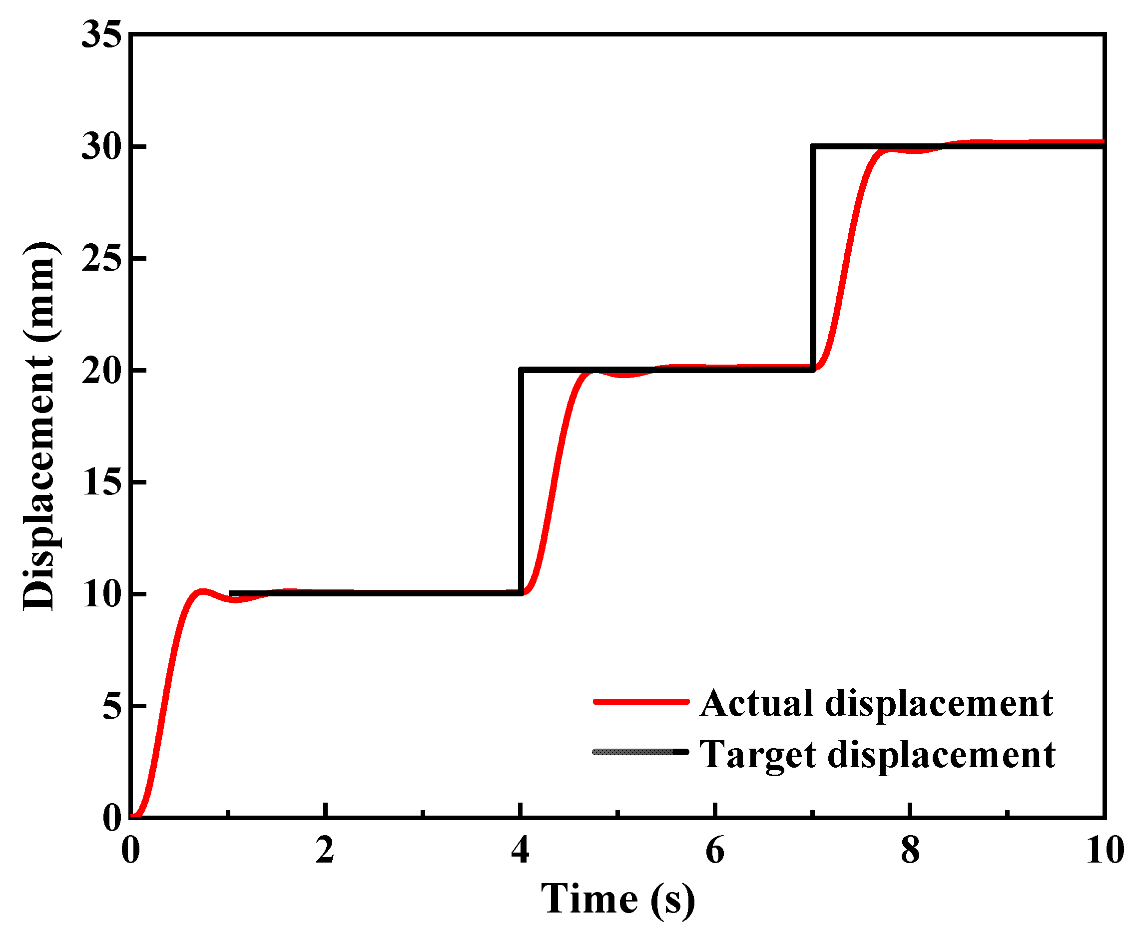
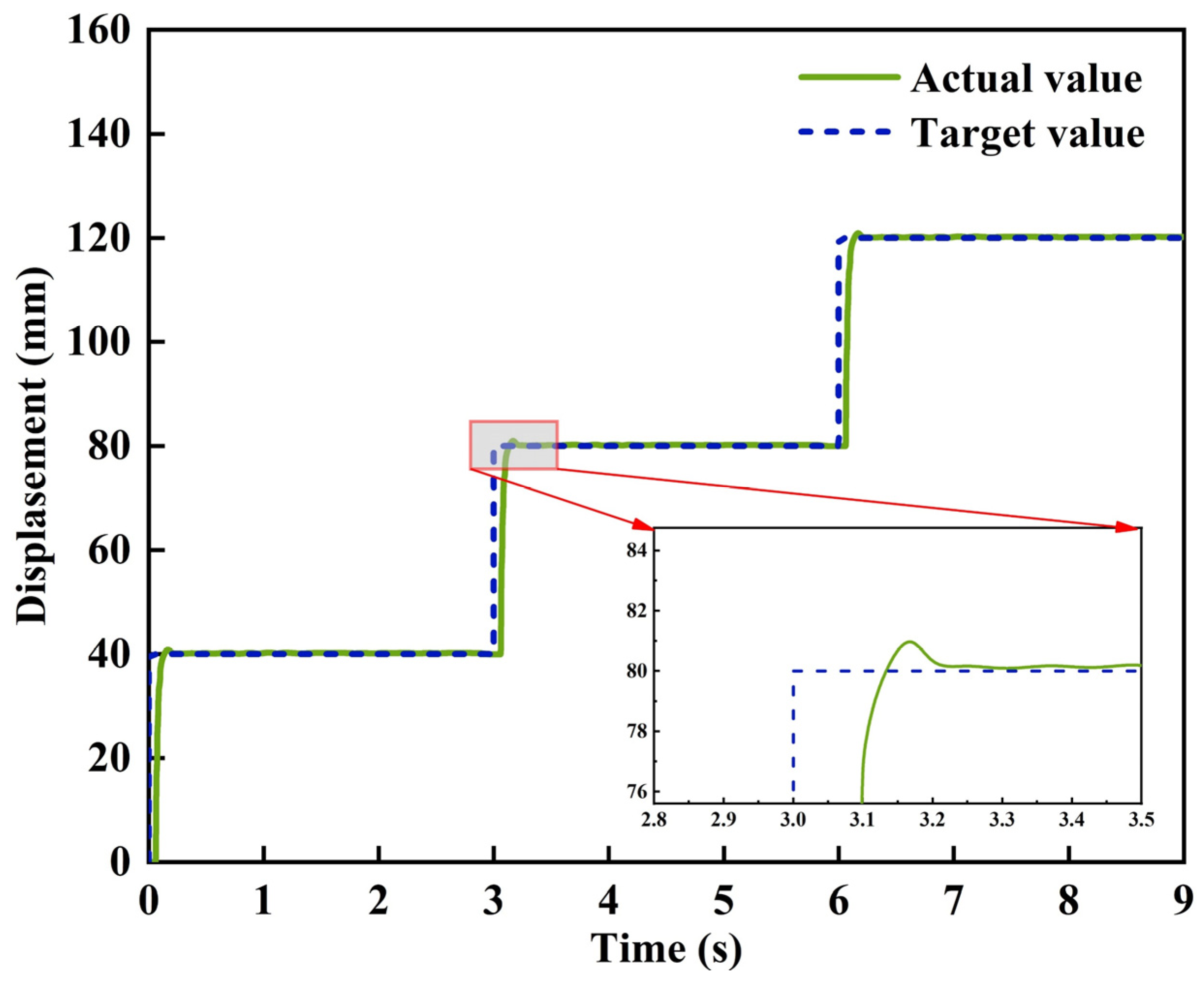
The pressure of the pressure relief valve used in the experiment is set to 0.3 MPa, and the sampling frequency is set to 100 Hz. The target values for the continuous step of the cylinder piston rod are set in the software as 40 mm, 80 mm, and 120 mm, and continuous step response tests are conducted on the cylinder. The experimental results are shown in Figure 15. To verify the stability of the system, statistical analysis is performed on the 100 Hz continuous sampling data (5 s duration). Step from 0 mm to 40 mm: The steady-state error (extracted from 1–5 s steady phase) has a mean of 0.3 mm and a standard deviation of 0.03 mm; Step from 40 mm to 80 mm: The steady-state error (extracted from 1.5–5 s steady phase) has a mean of 0.3 mm and a standard deviation of 0.04 mm; Step from 80 mm to 120 mm: The steady-state error (extracted from 2–5 s steady phase) has a mean of 0.3 mm and a standard deviation of 0.03 mm. The coefficient of variation (CV) of the steady-state error for all three step intervals is less than 15%, indicating good consistency and stability of the positioning accuracy. When the piston rod steps from 0 mm to 40 mm, the adjustment time is approximately 0.18 s, with an overshoot of about 1.2 mm; when stepping from 40 mm to 80 mm and 80 mm to 120 mm, the adjustment time is about 0.2 s, with an overshoot of about 1.4 mm. The results confirm the feasibility and stability of the control method. With the servo control of multiple single cylinders and the coordination of the posture detection system, it is theoretically possible to achieve precise control of the pneumatic vibration isolation platform.
The observed overshoot difference (0.2 mm in simulation vs. 1.4 mm in experiment) mainly stems from three core factors, which are idealized in simulation but unavoidable in practical applications. First is the idealized gas dynamics model in AMESim. The simulation assumes constant gas compressibility and negligible flow hysteresis of the proportional directional valve (model MPYE-5-1/8-HF-010B). However, in the experiment, real-time fluctuations in air pressure and temperature (the simulated ambient temperature is set to 297 K, while slight fluctuations exist in the test environment), as well as the nonlinear flow characteristics of the valve, lead to delayed pressure response in the cylinder chambers, thereby increasing the overshoot. Second is the influence of unmodeled mechanical friction. The simulation simplifies the Coulomb friction and viscous damping of the cylinder (model DSBC-32-20-PPVA-N3) and the cable transmission system into constant parameters. In practical applications, however, additional resistance generated by piston seal friction, cable wear, and installation errors causes an imbalance in the dynamic equilibrium of the servo system. Third is the measurement delay effect of the sensor. The selected laser displacement sensor (model HG-C1200) has an analog output delay of approximately 0.01 s for its 0–5 V signal, a factor not considered in the simulation. This results in a slight delay in the closed-loop control feedback, leading to temporary overshoot during the step response. Despite the aforementioned difference, the experimental overshoot (1.2–1.4 mm) still falls within the acceptable range for airborne electromagnetic detection (≤2 mm), fully validating the robustness of the proposed PID control strategy against practical disturbances.

5. Conclusions

This study presents a comprehensive study on the servo control system of the aerodynamic vibration isolation platform for airborne geophysical exploration. The goal is to suppress low-frequency vibration noise effectively and improve the depth and resolution of airborne electromagnetic surveys through the integration of high-performance vibration isolation platforms and active control technologies. Based on the design, modeling, simulation, and experimental validation of the proposed system, the following key conclusions have been drawn:
(a)
An aerodynamic vibration isolation platform based on CDPRs was successfully developed. By leveraging the advantages of CDPRs—including reduced structural weight, high-speed actuation, and enhanced workspace flexibility—a kinematic model of the aerodynamic vibration isolation platform was established. By deriving the vector closure principle and the Jacobian matrix, the target cable lengths can be calculated when the motion platform attitude is known, and the motion platform attitude can be solved when the cable lengths are known. Verification through MATLAB programming shows that the established kinematic model can accurately guide the software programming of the aerodynamic vibration isolation controller, providing a solid theoretical foundation for the subsequent control system design.
(b)
A proportional directional valve-controlled cylinder position servo system experimental platform was constructed, enabling precise control of the cylinder piston position through voltage control of the proportional directional control valve. Modeling and simulation were carried out using AMESim software. The model’s flow characteristics are consistent with the sample curves, exhibiting good linearity and dynamic performance, which can meet the control requirements of the aerodynamic vibration isolation platform for airborne geophysical exploration. Under PID control, the maximum overshoot of the cylinder piston’s actual displacement is controlled within 0.2 mm, which can satisfy the accuracy requirements for airborne electromagnetic aerodynamic vibration isolation. These results validate the correctness and feasibility of the designed pneumatic servo system.
(c)
A single-cylinder position servo control system was established. Tests on key control components led to the conclusion that the spool displacement of the proportional directional valve is directly proportional to the control voltage, with a good linear relationship and a maximum displacement of approximately 2.1 mm. Under different supply pressures, the proportional directional valve exhibits stable output pressure characteristics, enabling precise pressure control. The adjustment time of the cylinder piston rod at different target positions ranges from 0.18 s to 0.2 s, with an overshoot of about 1.2 to 1.4 mm and a steady-state error of approximately 0.3 mm. The experimental results confirm the positioning accuracy of the designed pneumatic servo control system and the feasibility of the control method.
This study focuses on the servo control system of a pneumatic vibration isolation platform for airborne geophysical exploration. It systematically addresses the critical issue of vibration noise isolation during airborne electromagnetic surveys, from theoretical design to experimental validation. By designing the pneumatic vibration isolation platform and applying active control technology, the accuracy and depth of airborne electromagnetic detection can be significantly improved, providing important technical support for the exploration and development of mineral resources. However, the system still has potential limitations: (1) Control strategy: Traditional PID control has limited adaptability to the nonlinearity of pneumatic systems (gas compressibility, valve flow hysteresis). When the supply pressure fluctuates by ±0.05 MPa, the steady-state error increases from 0.3 mm to 0.45 mm, and the overshoot increases from 1.4 mm to 1.8 mm. (2) Structural design: The elastic deformation of the rope (elongation ≤ 0.2 mm/m) reduces the high-frequency (>20 Hz) vibration isolation effect, and the optimization of the supporting cantilever angle does not consider the influence of temperature changes (−20 °C~50 °C) on material stiffness. (3) Application scenario: Experiments have not involved high-altitude (>5000 m) low-pressure environments, where reduced gas density may decrease the cylinder response speed.
Future research will focus on: (1) Optimizing control strategies: Introduce adaptive fuzzy PID control or sliding mode control to dynamically adjust parameters for the nonlinearity of pneumatic systems. (2) Improving structural design: Adopt carbon fiber ropes to reduce elastic deformation, and embed temperature compensation gaskets in supporting cantilevers to enhance stiffness stability. (3) Expanding environmental adaptability: Conduct high-altitude and wide temperature range experiments, establish the mapping model between pressure/temperature and cylinder performance, and optimize servo control parameters to adapt to extreme environments.

Author Contributions

Z.Z.: Writing—original draft, visualization, investigation, formal analysis, and conceptualization. H.Z.: Software and investigation. A.W.: Software and formal analysis. J.Y.: Writing—original draft and funding acquisition. H.T.: Software. M.Y.: Methodology. Z.J.: Methodology. M.A.: Writing—review and editing and methodology. All authors have read and agreed to the published version of the manuscript.

Funding

This research received no external funding.

Data Availability Statement

The original contributions presented in this study are included in the article. Further inquiries can be directed to the corresponding authors.

Acknowledgments

The authors are grateful for the support from China University of Geosciences (Beijing).

Conflicts of Interest

The authors declare that they have no known competing financial interests or personal relationships that could have appeared to influence the work reported in this paper.

Abbreviations

CDPRCable-driven parallel robot
AMESimAdvanced Modeling and Simulation Environment
PIDProportional–integral–derivative
AFMAGAirborne Frequency-Domain Magnetotelluric
CRISP-DMCross-Industry Standard Process for Data Mining
MAVISMicrogravity Active Vibration Isolation System
6-DOFSix degrees of freedom
EMIElectromagnetic interference
MRFMagnetorheological fluid
SMCSliding mode control
HGOHigh-gain observer
CVCoefficient of variation
ADCAnalog-to-digital converter

References

  1. Delhaye, R.; Rath, V.; Jones, A.G.; Muller, M.R.; Reay, D. Correcting for static shift of magnetotelluric data with airborne electromagnetic measurements: A case study from Rathlin Basin, Northern Ireland. Solid Earth 2017, 8, 637–660. [Google Scholar] [CrossRef]
  2. Prikhodko, A.; Bagrianski, A.; Kuzmin, P.; Sirohey, A. Natural field airborne electromagnetics—History of development and current exploration capabilities. Minerals 2022, 12, 583. [Google Scholar] [CrossRef]
  3. Okada, K. A historical overview of the past three decades of mineral exploration technology. Nat. Resour. Res. 2021, 30, 2839–2860. [Google Scholar] [CrossRef]
  4. Liang, S.; Sun, S.; Lu, H. Application of airborne electromagnetics and magnetics for mineral exploration in the Baishiquan–Hongliujing area, northwest China. Remote Sens. 2021, 13, 903. [Google Scholar] [CrossRef]
  5. Guo, Z.; Xue, G.; Liu, J.; Wu, X. Electromagnetic methods for mineral exploration in China: A review. Ore Geol. Rev. 2020, 118, 103357. [Google Scholar] [CrossRef]
  6. Ley-Cooper, A.Y.; Brodie, R.C.; Richardson, M. AusAEM: Australia’s airborne electromagnetic continental-scale acquisition program. Explor. Geophys. 2020, 51, 193–202. [Google Scholar] [CrossRef]
  7. Dzikunoo, E.A.; Vignoli, G.; Jørgensen, F.; Yidana, S.M.; Banoeng-Yakubo, B. New regional stratigraphic insights from a 3D geological model of the Nasia sub-basin, Ghana, developed for hydrogeological purposes and based on reprocessed B-field data originally collected for mineral exploration. Solid Earth 2020, 11, 349–361. [Google Scholar] [CrossRef]
  8. Sonkamble, S.; Chandra, S.; Pujari, P.R. Application of airborne and ground geophysics to unravel the hydrogeological complexity of the Deccan basalts in central India. Hydrogeol. J. 2022, 30, 2097–2116. [Google Scholar] [CrossRef]
  9. Yang, M.; Xiong, S.; Liang, S.; Tan, H. A study on the application of ATEM in hydrogeological investigation. Appl. Geophys. 2023, 20, 411–421. [Google Scholar] [CrossRef]
  10. Chandra, S.; Auken, E.; Maurya, P.K.; Ahmed, S.; Verma, S.K. Large scale mapping of fractures and groundwater pathways in crystalline hardrock by AEM. Sci. Rep. 2019, 9, 398. [Google Scholar] [CrossRef]
  11. Fan, J.; Hou, E.; Jin, D.; Xi, Z.; Long, X.; Zhou, S.; Nan, S.; Liu, Y.; Guo, K.; Ning, D. Application of opposing coils transient electromagnetic method in urban area with metal interference. J. Appl. Geophys. 2024, 228, 105467. [Google Scholar] [CrossRef]
  12. Bayramov, E.; Buchroithner, M.; Kada, M. Quantitative assessment of ground deformations for the risk management of petroleum and gas pipelines using radar interferometry. Geomat. Nat. Hazards Risk 2020, 11, 2540–2568. [Google Scholar] [CrossRef]
  13. Dubucq, D. Offshore oil slicks remote detection and discrimination from satellite data for monitoring. In Proceedings of the Earth Resources and Environmental Remote Sensing/GIS Applications XII; SPIE: Bellingham, WA, USA, 2021; Volume 11863, pp. 316–331. [Google Scholar] [CrossRef]
  14. Wang, L.; Kim, H.; Hansen, B.; Christiansen, A.V.; Vilhelmsen, T.N.; Caers, J. Statistical modeling of three-dimensional redox architecture from non-colocated redox borehole and transient electromagnetic data. Hydrogeol. J. 2023, 31, 1475–1490. [Google Scholar] [CrossRef]
  15. Lin, F.C.; Zheng, H.; Xiang, B.; Xu, R.; Jiang, W.; Lang, L. Vibration-Induced Noise in Extremely Low Frequency Magnetic Receiving Antennas. IEEE Antennas Wirel. Propag. Lett. 2021, 20, 913–917. [Google Scholar] [CrossRef]
  16. Li, L.; Wang, L.; Yuan, L.; Zheng, R.; Wu, Y.; Sui, J.; Zhong, J. Micro-vibration suppression methods and key technologies for high-precision space optical instruments. Acta Astronaut. 2021, 180, 417–428. [Google Scholar] [CrossRef]
  17. Li, D.; Wang, Y.; Lin, J.; Yu, S.; Ji, Y. Electromagnetic noise reduction in grounded electrical-source airborne transient electromagnetic signal using a stationarywavelet-based denoising algorithm. Near Surf. Geophys. 2017, 15, 163–173. [Google Scholar] [CrossRef]
  18. Gong, Y.; Fan, H.; Wei, X.; Liu, K.; Xu, X.; Che, K.; Li, D. Adaptive filtering suppression method of substation environmental noise based on fast transversal least mean square Algorithm. Int. J. Environ. Sci. Technol. 2025, 23, 116. [Google Scholar] [CrossRef]
  19. Ji, Y.; Li, D.; Yu, M.; Wang, Y.; Wu, Q.; Lin, J. A de-noising algorithm based on wavelet threshold-exponential adaptive window width-fitting for ground electrical source airborne transient electromagnetic signal. J. Appl. Geophys. 2016, 128, 1–7. [Google Scholar] [CrossRef]
  20. Zhu, K.; Peng, C.; Jing, C.; Fan, T.; Yang, Y. Suppression of motion noise based on a linear-homomorphic filtering algorithm in airborne electromagnetic survey. Geophys. Prospect. 2021, 69, 1102–1115. [Google Scholar] [CrossRef]
  21. Yuan, J.F.; Yan, S.T.; Yue, J.H. Design and dynamics study of very low frequency vibration isolation system for deep Earth airborne electromagnetic method. Chin. J. Geophys. 2025, 68, 299–311. [Google Scholar] [CrossRef]
  22. Jiao, X.; Zhang, J.; Li, W.; Wang, Y.; Ma, W.; Zhao, Y. Advances in spacecraft Micro-vibration suppression Methods. Prog. Aerosp. Sci. 2023, 138, 100898. [Google Scholar] [CrossRef]
  23. Ma, J.; Qin, F.; Gong, W.; Li, Y.; Che, H.; Yan, J.; Li, A. Multisensor Fusion: A High-Performance Effective Strategy for Active Vibration Isolation System in Atomic Gravimeter. IEEE Sens. J. 2025, 25, 43267–43279. [Google Scholar] [CrossRef]
  24. Liu, W.; Gao, Y.; Zhang, L.; Zou, T.; Yu, M.; Zheng, T. Flight test results for microgravity active vibration isolation system On-board Chinese Space Station. Npj Microgravity 2024, 10, 19. [Google Scholar] [CrossRef] [PubMed]
  25. Gong, Z.; Ding, L.; Li, S.; Yue, H.; Gao, H.; Deng, Z. Payload-agnostic decoupling and hybrid vibration isolation control for a maglev platform with redundant Actuation. Mech. Syst. Signal Process. 2021, 146, 106985. [Google Scholar] [CrossRef]
  26. Yang, J.; Deng, J.; Jiao, S.; Long, X. Global Multichannel Control Method for Helicopter Active Vibration Isolation. J. Guid. Control Dyn. 2025, 49, 401–417. [Google Scholar] [CrossRef]
  27. Lin, Z.; Chen, Y.; Wu, M.; Zheng, F. New bell plate controlled multi-inertia channel magnetorheological fluid mount wide frequency vibration isolation control Study. J. Intell. Mater. Syst. Struct. 2024, 35, 775–788. [Google Scholar] [CrossRef]
  28. Li, X.; Shao, J.; Wu, P.; Wang, T.; Yang, J.; Wu, Y. Multi-Frequency Vibration Suppression Based on an Inertial Piezoelectric Actuator Applied in Indoor Substations. Micromachines 2025, 16, 1178. [Google Scholar] [CrossRef]
  29. Song, H.; Shan, X.; Hou, W.; Wang, C.; Sun, K.; Xie, T. A novel Piezoelectric-based active-passive vibration isolator for low-frequency vibration system and experimental analysis of vibration isolation Performance. Energy 2023, 278, 127870. [Google Scholar] [CrossRef]
  30. Vo, N.Y.P.; Nguyen, M.K.; Le, T.D. Analytical study of a pneumatic vibration isolation platform featuring adjustable stiffness. Commun. Nonlinear Sci. Numer. Simul. 2021, 98, 105775. [Google Scholar] [CrossRef]
  31. Li, K.; Zhang, Y.; Wei, S.; Yue, H. Evolutionary algorithm-based friction feedforward compensation for a pneumatic rotary actuator servo system. Appl. Sci. 2018, 8, 1623. [Google Scholar] [CrossRef]
  32. Shinohara, Y.; Seki, K.; Iwasaki, M.; Chinda, H.; Takahashi, M. Controller design for dual-stage actuator-driven load devices considering suppression of vibration due to input saturation. In Proceedings of the 2013 IEEE International Conference on Mechatronics (ICM); IEEE: New York, NY, USA, 2013; pp. 742–747. [Google Scholar] [CrossRef]
  33. Jiang, S.; Wang, J.; Wang, S.; Shen, W. Vibration isolation control performance for an innovative 3-DOF parallel stabilization platform. J. Mech. Sci. Technol. 2022, 36, 3677–3689. [Google Scholar] [CrossRef]
  34. Kato, T.; Kawashima, K.; Sawamoto, K.; Kagawa, T. Active control of a pneumatic isolation table using model following control and a pressure differentiator. Precis. Eng. 2007, 31, 269–275. [Google Scholar] [CrossRef]
  35. Wei, W.; Tao, T.; Jian, H.; Guo, M.; Hu, N.; Yan, Q. On the hysteresis characteristics and compensation control strategy of a pneumatic hydrodynamic Retarder. Phys. Fluids 2024, 36, 027148. [Google Scholar] [CrossRef]
  36. Hong, Q.; Qi, J.; Wei, Q. Precision polishing force control technology of abrasive Belt-wheel polishing servo control system based on HGO-SMC. Adv. Mech. Eng. 2024, 16, 16878132241272160. [Google Scholar] [CrossRef]
  37. Wang, N.; Yin, C.C.; Gao, L.Q.; Su, Y.; Liu, Y.H.; Xiong, B. Airborne EM denoising based on curvelet transform. Chin. J. Geophys. 2020, 63, 4592–4603. [Google Scholar] [CrossRef]
  38. Zhang, Y.; Wang, L.; Li, L.; Wang, X.; He, S. Modeling and Analysis of Bio-Inspired, Reconfigurable, Piezo-Driven Vibration Isolator for Spacecraft. Biomimetics 2024, 9, 29. [Google Scholar] [CrossRef]
  39. Frankowski, P.K.; Majzner, P.; Mąka, M.; Stawicki, T.; Chady, T. Magnetic non-destructive evaluation of reinforced concrete structures—Methodology, system, and identification results. Appl. Sci. 2024, 14, 11695. [Google Scholar] [CrossRef]
  40. Fang, J.; Yin, C.; Gan, D. A Review of Cable-driven Parallel Robots. J. Vib. Eng. Technol. 2025, 13, 560. [Google Scholar] [CrossRef]
  41. Zhang, Z.; Shao, Z.; You, Z.; Tang, X.; Zi, B.; Yang, G.; Gosselin, C.; Caro, S. State-of-the-art on theories and applications of cable-driven parallel Robots. Front. Mech. Eng. 2022, 17, 37. [Google Scholar] [CrossRef]
  42. Jung, J. Workspace and Stiffness Analysis of 3D Printing Cable-Driven Parallel Robot with a Retractable Beam-Type End-Effector. Robotics 2020, 9, 65. [Google Scholar] [CrossRef]
  43. Jin, B.Q.; Chen, D.B.; Cheng, H. Research on Joint Simulation and Modeling of Electro-Hydraulic Position Servo System Based on Simulink and AMESim. Appl. Mech. Mater. 2011, 120, 563–566. [Google Scholar] [CrossRef]
  44. Liang, Q.; Wang, W.; Zhai, Y.; Sun, Y.; Zhang, W. Modeling and Fault Simulation of a New Double-Redundancy Electro-Hydraulic Servo Valve Based on AMESim. Actuators 2023, 12, 417. [Google Scholar] [CrossRef]
  45. Liu, H.; Zhao, Q. Numerical Experiments on Performance Comparisons of Conical Type Direct-Acting Relief Valve—With or without Conical Angle in Valve Element and Valve Seat. Processes 2023, 11, 1792. [Google Scholar] [CrossRef]
  46. Xiang, K.; Song, Y.; Ioannou, P. Nonlinear Adaptive PID Control for Nonlinear Systems. IEEE Trans. Autom. Control 2025, 70, 7000–7007. [Google Scholar] [CrossRef]
  47. Mu, S.; Shibata, S.; Baba, D.; Oshita, R. A Study on a Variable-Gain PID Control for a Pneumatic Servo System Using an Optimized PSO-Type Neural Network. Actuators 2025, 14, 250. [Google Scholar] [CrossRef]
  48. Zhao, R.; Chai, W.; Zhang, Y. Dynamics and experimental study of a novel proportional directional valve with displacement feedback groove controlled by High-speed switching Valves. Flow Meas. Instrum. 2024, 100, 102711. [Google Scholar] [CrossRef]
  49. Ledvoň, M.; Hružík, L.; Bureček, A.; Polášek, T.; Dýrr, F.; Kolář, D. Experimental and Numerical Analysis of Flow Force Acting on the Spool of Proportional Directional Valve. Processes 2023, 11, 3415. [Google Scholar] [CrossRef]
Figure 1. (a) 3D CA model of the pneumatic vibration isolation platform. (b) Detailed schematic diagram of the pneumatic vibration isolation platform structure.
Signals 07 00030 g001
Figure 2. (a) Schematic diagram of airborne electromagnetic exploration. (b) Photograph of the vibration isolation platform.
Signals 07 00030 g002
Figure 4. Z–X–Y Euler angle rotation sequence for the moving platform.
Signals 07 00030 g004
Figure 5. Schematic diagram of the single-cylinder servo system.
Signals 07 00030 g005
Figure 6. AMESim model of the proportional directional valve.
Signals 07 00030 g006
Figure 7. AMESim model of the single-cylinder servo system.
Signals 07 00030 g007
Figure 8. Actual simulated displacement.
Signals 07 00030 g008
Figure 9. Schematic diagram of the displacement test for the proportional directional valve core.
Signals 07 00030 g009
Figure 10. Test results of the proportional directional valve core.
Signals 07 00030 g010
Figure 11. Schematic diagram of valve port area test.
Signals 07 00030 g011
Figure 12. Valve port area and simulated voltage curve diagram.
Signals 07 00030 g012
Figure 13. (a) Pneumatic servo controller functional board diagram; (b) physical image of the pneumatic servo controller.
Signals 07 00030 g013
Figure 14. Single-cylinder continuous step response test platform.
Signals 07 00030 g014
Figure 15. Continuous step response test.
Signals 07 00030 g015
Table 1. Performance comparison between PID control and advanced controllers.
Control StrategySteady-State Error (mm)Adjustment Time (s)Robustness (Pressure Fluctuation ± 0.05 MPa)Engineering Complexity
PID control (proposed)0.30.18–0.2Steady-state error change 0.15 mmSimple (three-parameter tuning)
Adaptive robust control0.20.25Steady-state error change 0.05 mmComplex (parameter identification required)
Fuzzy PID control0.250.22Steady-state error change 0.08 mmModerate (20+ fuzzy rules)
Table 2. Selection of pneumatic components.
No.ComponentModelParameterTolerance
1CylinderDSBC-32-20-PPVA-N3Stroke 200 mm, bore diameter 32 mm±0.1 mm
2Air TubeNPS 6Diameter 6 mm±0.05 mm
3Air CompressorEWS 24150 L/min, working pressure 0.3 MPa±0.02 MPa
4Proportional Directional ValveMPYE-5-1/8-HF-010B0–10 V control voltage, rated flow 700 L/min±0.01 V
5Filter Pressure RegulatorMS2-LFR-M6-D6-C-P-M-AR-MPA-B0.1–1 Mpa adjustment range±0.01 MPa (applicable to 0.3–0.8 MPa operating range)
6Laser Displacement SensorHG-C12000–5 V output, measurement range ±100 mm±0.03 mm
7DC Power SupplyVE-500-2424 V/20 A±0.1 V
8Single-Cylinder Servo ControllerCustom-madeCustom-made-
Disclaimer/Publisher’s Note: The statements, opinions and data contained in all publications are solely those of the individual author(s) and contributor(s) and not of MDPI and/or the editor(s). MDPI and/or the editor(s) disclaim responsibility for any injury to people or property resulting from any ideas, methods, instructions or products referred to in the content.