Article

Transient Vibro-Acoustic Characteristics of Double-Layered Stiffened Cylindrical Shells

1
Yantai Research Institute, Harbin Engineering University, Yantai 264000, China
2
College of Shipbuilding Engineering, Harbin Engineering University, Harbin 150001, China
3
School of Naval Architecture & Ocean Engineering, Jiangsu University of Science and Technology, Zhenjiang 212001, China
*
Author to whom correspondence should be addressed.
Acoustics 2025, 7(3), 50; https://doi.org/10.3390/acoustics7030050
Submission received: 1 June 2025 / Revised: 8 August 2025 / Accepted: 18 August 2025 / Published: 21 August 2025

Abstract

This study investigates the underwater transient vibro-acoustic response of double-layered stiffened cylindrical shells through an integrated experimental-numerical approach. Initially, vibration and noise responses under transient impact loads were experimentally characterized in an anechoic water tank, establishing benchmark datasets. Subsequently, based on the theory of transient structural dynamics, a numerical framework was developed by extending the time-domain finite element/boundary element (FEM/BEM) method, enabling comprehensive analysis of the transient vibration and acoustic radiation characteristics of submerged structures. Validation through experimental-simulation comparisons confirmed the method’s accuracy and effectiveness. Key findings reveal broadband features with distinct discrete spectral peaks in both structural vibration and acoustic pressure responses under transient excitation. Systematic parametric investigations demonstrate that: (1) Reducing the load pulse width significantly amplifies vibration acceleration and sound pressure levels, while shifting acoustic energy spectra toward higher frequencies; (2) Loading position alters both vibration patterns and noise radiation characteristics. The established numerical methodology provides theoretical support for transient impact noise prediction and low-noise structural optimization in underwater vehicle design.

1. Introduction

With the increasing exploitation of marine resources and growing demands for national defense security, ships and offshore structures are facing increasingly stringent challenges in their service environments.
Underwater vehicles are often subjected to transient impact loads such as equipment shocks and marine environment attack when sailing in water. Such loads can induce intense vibroacoustic radiation from the structure. The resulting transient noise is characterized by high instantaneous amplitude, broad frequency bandwidth, and long propagation distance. This transient noise has emerged as a critical factor that can readily expose the navigation of underwater vehicles during their operations. In this context, the double-layered stiffened cylindrical shell structure has become a fundamental component for studying vibration and noise in underwater vehicle structures due to its high similarity to the actual structure of underwater vehicles. Furthermore, the vibration transmission path in both structures involves energy transfer from the inner shell through connecting structures like ring stiffeners to the outer shell, where vibration of the outer shell directly radiates sound waves into the water.
Investigating the transient vibro-acoustic radiation of double-layered cylindrical shells is essential. Current research on the vibro-acoustic radiation of cylindrical shell structures underwater primarily focuses on frequency-domain analyses, employing methods such as analytical approaches [1], numerical methods [2], and experimental techniques [3,4]. Kingan [5] employed the Wave and Finite Element (WFE) method to predict sound propagation and radiation through an infinite cylindrical structure. Mancoin [6] utilized the Wave Finite Element formulation for a 2D waveguide to obtain numerical calculations of wave propagation in a laminated cylindrical shell with internal fluid and residual stresses. However, these methods are mainly suited for solving steady-state vibro-acoustic radiation noise and exhibit significant limitations when applied to transient vibro-acoustic radiation studies. Regarding transient vibro-acoustic radiation of structures, Ross and Ostiguy [7] pioneered an analytical model based on thin plate theory to study the near-field initial transient noise generated by a rigid sphere impacting a plate structure. Their results showed excellent agreement with experimental data. Li [8] developed an efficient modeling technique based on the scaled boundary finite element method for transient vibro-acoustic analysis of plates and shells, validating the method’s effectiveness through numerical examples. Aimi et al. [9] addressed the propagation of acoustic and elastic waves in two-dimensional unbounded domains. They proposed a high-performance BEM acceleration based on the pivoted ACA algorithm, which significantly reduced computation time. Gao et al. [10] presented a time-domain boundary element method (TDBEM) for three-dimensional acoustic problems utilizing a kernel function library. The effectiveness of their method was demonstrated through experiments involving a pulsating sphere and sound propagation in a vocal tract. Takahashi et al. [11] enhanced the fast time-domain boundary element method for the three-dimensional wave equation, improving the practicality of the TDBEM for solving three-dimensional scalar wave problems. Chen [12] employed the Chebyshev-Lagrangian method to study the free vibration and transient response of GPL-FG cylindrical shells, analyzing the influence of structural material parameters and boundary conditions on these responses. Liu et al. [13] extended the reverberation-ray matrix method to investigate the transient response of ring-stiffened composite cylindrical shells under impact loads. Dalton et al. [14] expanded steady-state frequency response predictions to transient response predictions using the computer code MANIA. Zou et al. [15] transformed the vibro-acoustic frequency-domain equations into time-domain equations using Fourier transforms and convolution integrals. They described the nonlinear stiffness and damping of vibration isolators using polynomial forms and proposed a time-domain calculation method for the acoustic radiation of underwater vehicles. Shi et al. [16] conducted a numerical analysis of underwater radiated noise from polar transport vessels under continuous ice-breaking conditions using the S-ALE algorithm. Menton et al. [17] investigated the radiated noise from a hollow spherical shell filled with fluid and subjected to internal transient pulse loads. Chappell et al. [18] proposed a theoretical model capable of accurately simulating transient acoustic radiation from thin elastic spherical shells under various fluid-structure interaction conditions. Christoforou et al. [19] derived analytical solutions for simply supported orthotropic cylindrical shells under impact loads through double Fourier series expansions of loads, displacements, and rotations. Hoai et al. [20] analyzed the vibration characteristics of functionally graded triply periodic minimum surface (TPMS) sandwich curved double-shells under low-velocity impact loads through geometric analysis. Pandey et al. [21] employed time-domain Rayleigh integrals to determine the far-field radiated sound pressure and utilized the elementary radiator method for numerical solution, conducting an analysis of transient vibration and sound radiation for simply supported functionally graded sandwich plates. Liu et al. [22] performed a semi-analytical study on the free vibration and transient dynamic behavior of functionally graded material (FGM) sandwich plates using the scaled boundary finite element method (SBFEM), demonstrating the method’s high accuracy and efficiency in the dynamic analysis of sandwich plates. Chappell et al. [23] introduced an advanced transient boundary element method (BEM) for modeling structural transient acoustic radiation. This method reformulates the Burton and Miller-type equations in the time domain via integral equation reconstruction, effectively overcoming the low-stability limitations of conventional transient BEM in simulating transient acoustic radiation. Geng et al. [24] accurately reconstructed transient sound fields using a sparse real-time nearfield acoustic holography (NAH) method and further validated the method’s effectiveness through experiments involving an impacted steel plate. Chen et al. [25] combined the reduced transformation method with the TLEA method to establish an uncertainty analysis method for transient vibro-acoustic problems with fuzzy uncertainties, verifying the method’s accuracy through simulation calculations. Li et al. [26] predicted structural dynamic responses using a novel machine learning approach based on Graph Neural Networks (GNNs), achieving favorable results.
Regarding the identification and assessment methods for transient noise, Hu [27] proposed Wavelet Packet Denoising and Empirical Mode Decomposition (EMD) Denoising methods for denoising noisy signals. The Wavelet Packet Denoising approach was able to clearly preserve the time-frequency characteristics of the original signal, enabling the identification of transient signals through time-frequency diagrams. Liu [28] established a comparative platform for transient noise under different operational conditions based on transient signal energy calculation, enabling the assessment of ship-radiated transient noise. Yu [29] employed a power-law algorithm to conduct “sensitivity” analysis on transient signal waveforms. By integrating line-spectrum extraction techniques and wavelet transforms, they achieved rapid identification of the effective analysis duration for ship transient noise. Leissing [30] utilized Xtract, a specialized component designed for automatic signal separation, to isolate and process signals individually, thereby enhancing the understanding of underwater transient noise phenomena.
Based on the current research status, it is evident that scholars have conducted extensive research on both steady-state and transient vibration noise of single-layered cylindrical shells, elastic spheres, and sandwich plates. Gao et al. [31] established a steady-state vibro-acoustic prediction model for a single-layered stiffened cylindrical shell under broadband excitation, validating the accuracy of experimental test results. Double-layered cylindrical shells outperform single-layer shells in mechanical and acoustic properties. Modern underwater vehicles typically use double-hull structures. Actual engineering scenarios also involve many transient excitations. Therefore, this paper introduces a new double cylindrical shell configuration and an impact load excitation mode. At the same time, the calculation of steady-state vibration and noise is extended to transient state.
Therefore, this study employs an integrated experimental-numerical approach to investigate the underwater transient vibro-acoustic radiation of double-layered cylindrical shells. Initially, experimental measurements characterized the vibro-acoustic radiation under transient impact loads. Concurrently, based on explicit dynamics theory and the acoustic wave equation, a prediction methodology for underwater transient radiated noise from ship structures was developed using the integrated time-domain explicit FEM/transient BEM coupling method. This approach directly solves the radiated noise induced by structural responses under shock loads, thereby avoiding the limitation of the WFEM method which is applicable only to steady-state scenarios. Subsequently, the simulated vibration and noise responses were compared with experimental results to ensure the accuracy of the simulation results. Finally, wavelet transform was applied to analyze the transient signals, ensuring more precise identification of the wave propagation mechanisms governing impact noise. By systematically investigating the influence of pulse width and loading position of transient impact loads on the transient vibro-acoustic radiation characteristics of the double-layered cylindrical shell, this work provides theoretical support for the prediction and analysis of transient vibration and noise in underwater vehicles under typical operating conditions.

2. Prediction Method for Noise Under Transient Impact Loads

2.1. Transient Structural Dynamics Theory

Transient structural dynamics problems are typically solved through numerical integration methods. Therefore, in this study, the explicit dynamics method based on the central difference method is employed to calculate the vibration response of the double-layered stiffened cylindrical shell under transient impact loads. The solution procedure is as follows.
M u ¨ + C u ˙ + K u = F ( t )
In the equation, M is the mass matrix, C is the damping matrix, K is the stiffness matrix, u ¨ is the acceleration vector, u ˙ is the velocity vector, u is the displacement vector, F ( t ) is the load vector. For transient analysis, the damping matrix is typically modeled using the Rayleigh damping formulation:
C = α M + β K
where: α is the mass-proportional damping coefficient, β is the stiffness-proportional damping coefficient. These coefficients can be determined from the modal damping ratios of the structure using the relationship.
The coefficients α and β can be determined from the modal damping ratios ξ of the structure and the natural frequencies of structures w .
α = 2 w i w j ( ξ i w j ξ j w i ) w j 2 w i 2
β = 2 ( ξ i w j ξ j w i ) w j 2 w i 2
The central difference method is employed to integrate the equations of motion in time. For a single node, where the damping matrix and stiffness matrix terms vanish, the resultant force F ( t ) acting on the node equals the difference between the generalized external force P and the generalized internal force I . The equilibrium equation thus simplifies to:
M u ¨ = P I
Considering the time increment from the initial step to time t, the acceleration is expressed as:
u ¨ ( t ) = M 1 ( P I ) ( t )
On the premise that the time increment step is small enough, the central difference method is used to integrate the acceleration in the time domain, then the initial velocity of the current analysis step:
u ˙ | ( t + Δ t 2 ) = u ˙ | ( t Δ t 2 ) + ( Δ t ( t + Δ t ) + Δ t ( t ) ) 2 u ¨ | ( t )
Then the final displacement of the current analysis step is:
u | ( t + Δ t ) = u | ( t ) + Δ t | ( t + Δ t ) u ˙ | ( t + Δ t 2 )
The above equation demonstrates that during explicit solution procedures, the structural dynamic response of nodes depends solely on the time increment step. Therefore, the central difference method employs extremely small stable time increments and a large number of incremental steps to ensure computational accuracy and stability.
For submerged structures, the influence of fluid-structure coupling must be considered. The acoustic wave equation for small-amplitude perturbations in an ideal fluid medium is given by:
M a P ¨ + C a P ˙ + K a P = F a
M a , C a and K a are the acoustic mass matrix, damping matrix and stiffness matrix, respectively, and F is the external excitation load matrix. Considering the influence of fluid-structure interaction, the structural dynamics equation becomes:
M s u ¨ + C s u ˙ + K s u + K s a P = F s
Combining Formulas (9) and (10), a complete acoustic-structural coupling equation is obtained, namely:
M s 0 M s a M a u ¨ P ¨ + C s 0 0 C a u ˙ P ˙ + K s M s a 0 K a u P = F s F a
where K s a and M s a represent the coupling stiffness matrix and the coupling mass matrix, respectively.

2.2. Boundary Element Theory Based on Wave Equation

The transient radiated sound field is solved using a time-domain boundary element method (TDBEM) based on the wave equation. As illustrated in the Figure 1, the acoustic domain Ω represents the spatial sound field solution region, where: Γ denotes the sound propagation boundary, Y indicates the field point, X corresponds to the source point, n represents the outward normal direction of the boundary.
The acoustic wave equation for small-amplitude perturbations in an ideal fluid medium is given by:
2 p ( Y , t ) 1 c 2 2 p ( Y , t ) t 2 = 0
where: c is the speed of sound in the medium, 2 denotes the Laplace operator, p is the sound pressure, t is time variable.
Based on the wave equation, boundary conditions, and initial conditions, the time-domain boundary integral equation for acoustic waves can be derived using the δ function through Laplace transform and inverse transform:
C ( Y ) p ( Y , t ) + Γ 0 t q * ( Y , t ; X , τ ) p ( X , τ ) d τ d Γ = Γ 0 t p * ( Y , t ; X , τ ) q ( X , τ ) d τ d Γ
where: C ( Y ) represents the geometric shape parameter of the boundary surface and p * ( Y , t ; X , τ ) denotes the fundamental solution of acoustic pressure at field point Y .
Equation (13) indicates that the acoustic pressure at any point in the sound field at a given time is the superposition of sound waves radiated from each infinitesimal area element d Γ on the structural boundary Γ at all preceding times. Therefore, the acoustic pressure at any point within the solution domain Ω can be determined by computing the acoustic pressure and flux on the boundary Γ . In the solution of structural vibration-induced sound radiation, the acoustic flux can be derived from the structural vibration response, and the acoustic pressure at any point on Γ can be calculated as follows:
C p n + m = 1 n ¯ α = 1 n a H ( n m + 1 ) [ α ( m ) ] p ( α g ) = m = 1 n ¯ α = 1 n a G ( n m + 1 ) [ α ( m ) ] q ( α g )
In the equation: p n denotes the nodal acoustic pressure vector at time step n , p ( α g ) and q ( α g ) represent the global vectors formed by the acoustic pressure and flux, respectively, at all nodes by integrating the structural vibration response results, H and G are the known sound field moments related to the initial state, the acoustic pressure p ^ n at any point in the solution domain Ω and at any time instant can be expressed as:
p ^ n = m = n i n ¯ α = 1 n n H ( n m + 1 ) [ α ( m ) ] p ( α g ) + m = n i n ¯ α = 1 n n G ( n m + 1 ) [ α ( m ) ] q ( α g )
where: n i = m a x ( 1 , n ¯ n m a x + 1 ) , n m a x = r m a x / ( c Δ t ) + 2 .

2.3. Transient Signal Analysis Method

To analyze time-domain signals in the frequency domain, the conventional Fast Fourier Transform (FFT) is typically employed to examine the signal spectrum, as expressed by the following equation:
C ( ω ) = + f ( t ) e i w t d t
In the equation, C ( w ) represents the frequency-domain signal obtained after the Fast Fourier Transform (FFT), and f ( t ) denotes the time-domain non-stationary signal. However, this method is unsuitable for analyzing signals whose frequency or amplitude varies with time. For such cases, time-frequency analysis methods are typically employed for signal analysis.
The wavelet transform is a mathematical tool that exhibits localization characteristics in both the time and frequency domains. Building upon the time-frequency analysis concept of the short-time Fourier transform, this method further overcomes the limitation of fixed window sizes by achieving dynamically adjustable “time-frequency” analysis windows, making it an ideal choice for signal time-frequency processing. The wavelet transform is defined as follows:
C ( a , b ) = + f ( t ) Ψ ( a , b ) d t
In the equation, Ψ ( a , b ) represents the wavelet function, a is the scaling factor of wavelet, b is the translation factor of wavelet. By adjusting the a and b parameters, the wavelet transform achieves localized characteristics, functioning as both a time-domain and frequency-domain representation.

2.4. Prediction Process of Underwater Transient Radiated Noise of Ship Structure

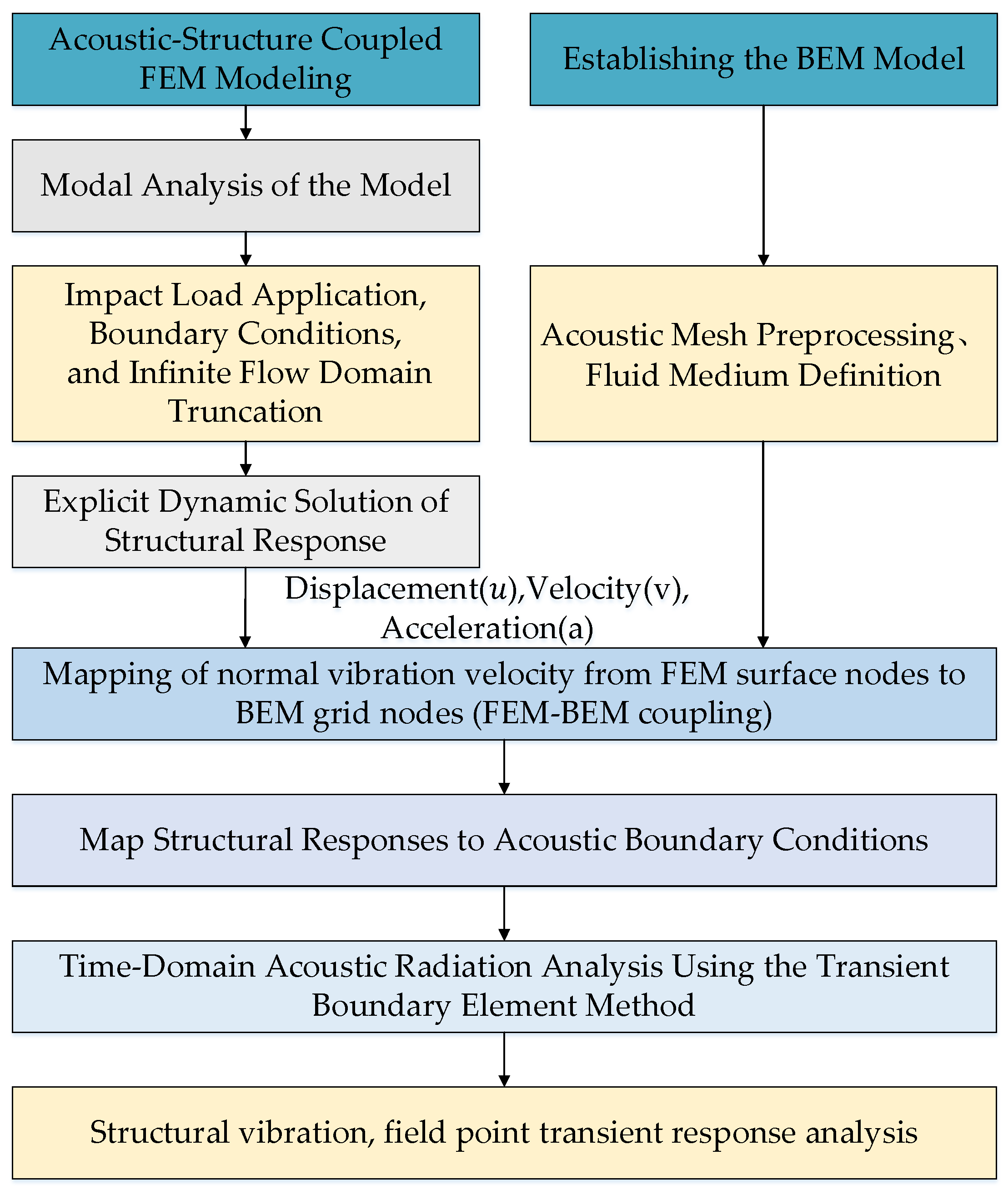
Integrating the two aforementioned theories, the analytical procedure for the direct time-domain near-field analysis of radiated noise under transient impact loads is established as follows:
(1)
Divide the prediction solution for transient radiated noise into structural vibration response solution and radiated noise solution. Develop separate structural finite element (FEM) and acoustic boundary element (BEM) models. Subsequently, perform modal analysis on the FEM model to characterize its vibration behavior, and conduct preprocessing of the structural-acoustic mesh and fluid medium definition for the BEM model.
(2)
Define the boundary conditions and external fluid domain for the FEM model to approximate realistic operational conditions. Then, based on explicit dynamics, solve the transient vibration response of the structure under various impact loads.
(3)
Input the structural vibration response obtained in the previous step as boundary conditions for the acoustic field. Solve the acoustic boundary integral equation using the time-domain boundary element method (BEM) to obtain the time-varying acoustic pressure distribution within the fluid field.
(4)
Perform time-frequency characteristic analysis on the structural transient vibration response and acoustic radiation using wavelet transform.
The Boundary Element Method (BEM) for calculating radiated noise requires only the mesh of the structure’s radiating surface and the normal vibration velocity of the nodes on that surface. Therefore, the structural vibration results file from the Finite Element Method (FEM) calculation must be imported into the BEM software (VIRTUAL.LAB). The normal vibration velocity of the structural surface nodes is then transferred to the BEM grid nodes through surface mapping, thereby achieving FEM-BEM coupling. This mapped velocity serves as the boundary condition for the radiated noise calculation, enabling the computation of the acoustic pressure magnitude at the field points. The finite element software used in this process is ABAQUS (Version number is 6.14.2), and the boundary element software is VIRTUAL.LAB (Version number is 13.10), in which the fluid-structure interaction is solved as an approximate solution based on boundary data transmission. The acoustic calculation only considers the excitation effect of structural vibration on the sound field of the flow field, and the reaction of the sound field to the structure is ignored. The setting of non-reflective boundary conditions is to better simulate the real experimental environment. The non-reflecting boundary condition belongs to the absorbing boundary condition, which makes the plane wave incident on the boundary completely project out, and no reflected wave returns to the computational domain. The specific flow chart is Figure 2.

3. Validation of Transient Impact Noise Calculation Method

3.1. Introduction of Double Stiffened Cylindrical Shell Model

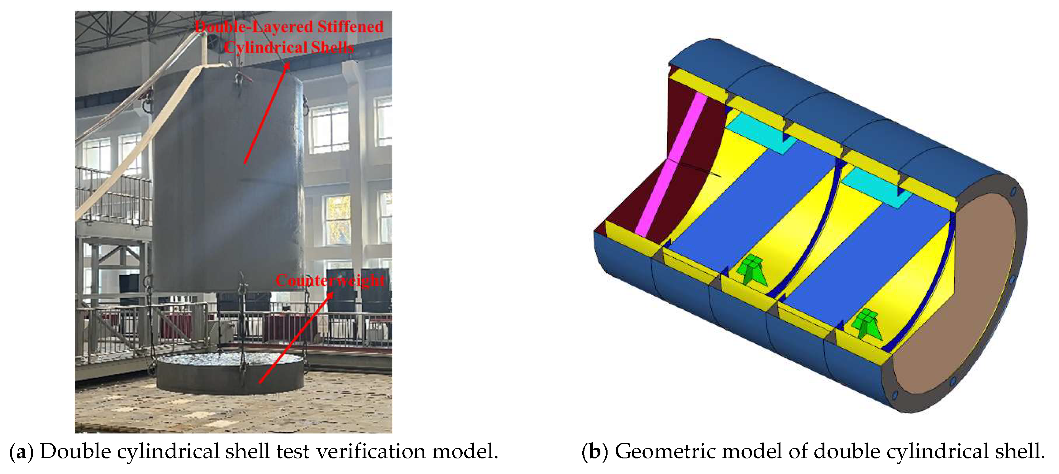
The double-layered stiffened cylindrical shell serves as both a primary structural component and a simplified model for underwater vehicles. In this study, we investigate the transient vibro-acoustic and sound radiation characteristics of this structure. To facilitate a comprehensive analysis of its vibro-acoustic behavior, the three-dimensional model and experimental setup of the stiffened cylindrical shell are illustrated in Figure 3.
The double-layered stiffened cylindrical shell consists of steel for both the inner and outer shells as well as the ribs, with the following material properties: density ρ = 7800 kg/m3, Poisson’s ratio μ = 0.3, Young’s modulus E = 2.1 × 10¹¹ Pa, The Rayleigh damping coefficients are determined as follows: α = 1.1618, β = 2.15 × 10⁻⁵. The structure features simply-supported boundary conditions at both ends. Four equally-spaced ring stiffeners are arranged along the longitudinal direction, with two end caps installed at both extremities of the cylindrical shell. The surrounding fluid medium is water, characterized by a density ρ 0 = 1000 kg/m3 and sound speed c = 1500 m/s. For experimental requirements, a 1400 kg counterweight is designed and suspended via lifting lugs at the bottom of the cylindrical shell to balance buoyancy during underwater testing. The key structural parameters are summarized in Table 1.

3.2. Experiment Content

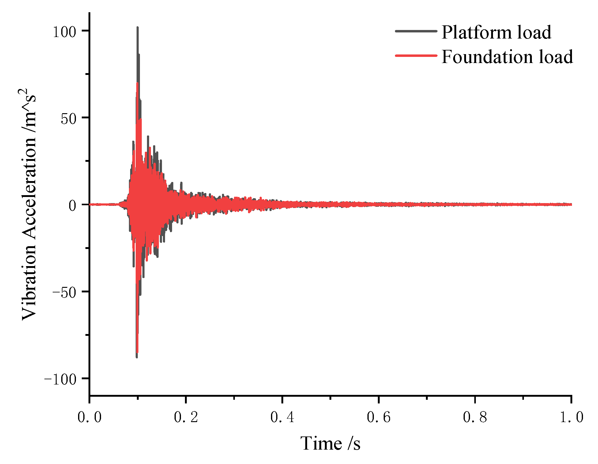
Experiments were conducted in the anechoic water tank at Harbin Engineering University. During testing, a crane hoisted the model to its designated position. The model was fully submerged. The upper surface of the cylindrical shell was maintained 2.1 m below the water’s free surface. Two exciters were installed inside the double-layered stiffened cylindrical shell to generate radial transient excitation forces, inducing forced vibrations and radiated noise from the structure. The excitation positions is shown by M2 and M4 in Figure 4. The red asterisk refers to load excitation point. The loading positions were set with reference to the actual equipment locations in underwater vehicles. They are the center of the lower base panel and the side of the upper platform respectively, and the direction of action is towards the outside of the cylindrical shell. The excitation forces applied by the exciters to the cylindrical shell were measured using a CL-YD-302 piezoelectric force sensor with a sensitivity of 4 pC/N. The manufacturer of the piezoelectric force sensor is Chisler in Winterthur, Switzer-land. The exciter model is JZK-50, employing a transient impact signal as the control input with a signal bandwidth of 20,000 Hz. The manufacturer of the exciter is China Jiangsu Energy Electronics Technology Co., Ltd. The sampling rate of the signal acquisition system is 20,000 Hz, ensuring all the collected signals shared a consistent time reference. The upper frequency limit of the numerical simulation results is related to the size of the model grid. If the grid is too small, the calculation time will be greatly increased. Therefore, this paper mainly focuses on 0–2000 Hz. Figure 5 also illustrates the radial pulse loads recorded by accelerometers mounted on the experimental model under exciter actuation. The abscissa T denotes time.
Seven DH1A111E vibration acceleration sensors with a sensitivity of 100 mV/g were mounted on the inner surface of the cylindrical shell. The specific arrangement of the vibration acceleration assessment points is illustrated in Figure 6a, where sensors were spaced at 60° intervals circumferentially around the mid-section of the cylindrical shell, with an additional sensor installed directly below the base. The red asterisk refers to vibration acceleration assessment points. Due to the symmetrical structure of the double-layered cylindrical shell, a cross-sectional schematic is presented. The hydrophone model was B&K8104 with a sensitivity of 56 μV/Pa, and it was calibrated enough. The hydrophones were positioned at a horizontal distance of 5 m from the center of the cylindrical shell. Since the hydrophones were placed within the reverberation radius, the influence of reflected waves could be neglected. The four hydrophones were arranged circumferentially around the exterior of the cylindrical structure, with their layout shown in Figure 6b. The red asterisk refers to sound pressure assessment point.

3.3. Numerical Model of Double Stiffened Cylindrical Shell

The structural finite element model and acoustic boundary element model of the stiffened cylindrical shell are illustrated in Figure 7. The computational framework adheres to linear theory assumptions: material behavior conforms to Hooke’s law; displacements and rotations are sufficiently small; boundary conditions remain invariant during vibration. Specifically, both ends of the structural model are defined with simply-supported boundary conditions.
To meet the analysis accuracy requirements, the structural mesh was refined to ensure the element length Δ x λ min / 6 ( λ min represents the minimum bending wavelength), as illustrated in the accompanying figure. An acoustic-structure coupled model of the underwater double-layered stiffened cylindrical shell was established using acoustic meshes. The outer shell of the cylindrical structure was coupled with the water medium. To prevent wave reflections at the fluid domain boundaries, a zero-impedance non-reflective boundary condition was applied. The fluid truncation radius
R f 0.2 λ + r
where: λ denotes the acoustic wavelength corresponding to the lower analysis frequency, r represents the radius of the outer shell.
The structural finite element mesh size for the double-layered stiffened cylindrical shell was set to 0.025 m, with the structural finite element model comprising a total of 43,674 elements. The acoustic boundary element mesh size was 0.06 m, and the acoustic boundary element model consisted of 8722 elements. The cylindrical shell was coupled with the water medium.

3.4. Comparative Analysis of Transient Vibration Response

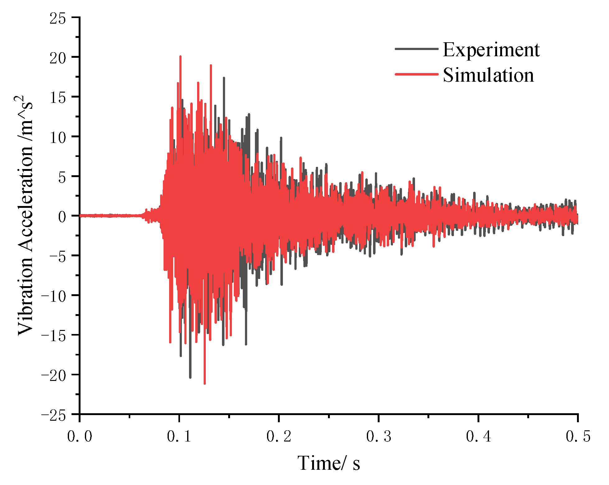
The underwater transient vibration experiment of the stiffened cylindrical shell was successfully completed. The transient structural dynamics method was employed to solve the vibration response induced by transient impact loads, and the experimental results were compared with numerical simulations for validation.
Figure 8 presents a comparative analysis of experimental and numerical time-domain vibration acceleration curves at assessment point A7 during the initial 0.5-s period. The abscissa f denotes the frequency. The results demonstrate that under pulse excitation, the vibration acceleration of the cylindrical shell surface rapidly increases. Under pulse excitation, the vibration acceleration of the cylindrical shell surface increases rapidly. After the pulse load disappears, the damped free vibration occurs under the influence of damping. The vibration acceleration response first shows a short-term growth trend, reaching a peak value around 110 ms, and then decays rapidly. Notably, the time-domain numerical simulation results for the vibration response at assessment point A7 show excellent agreement with the experimental measurements.
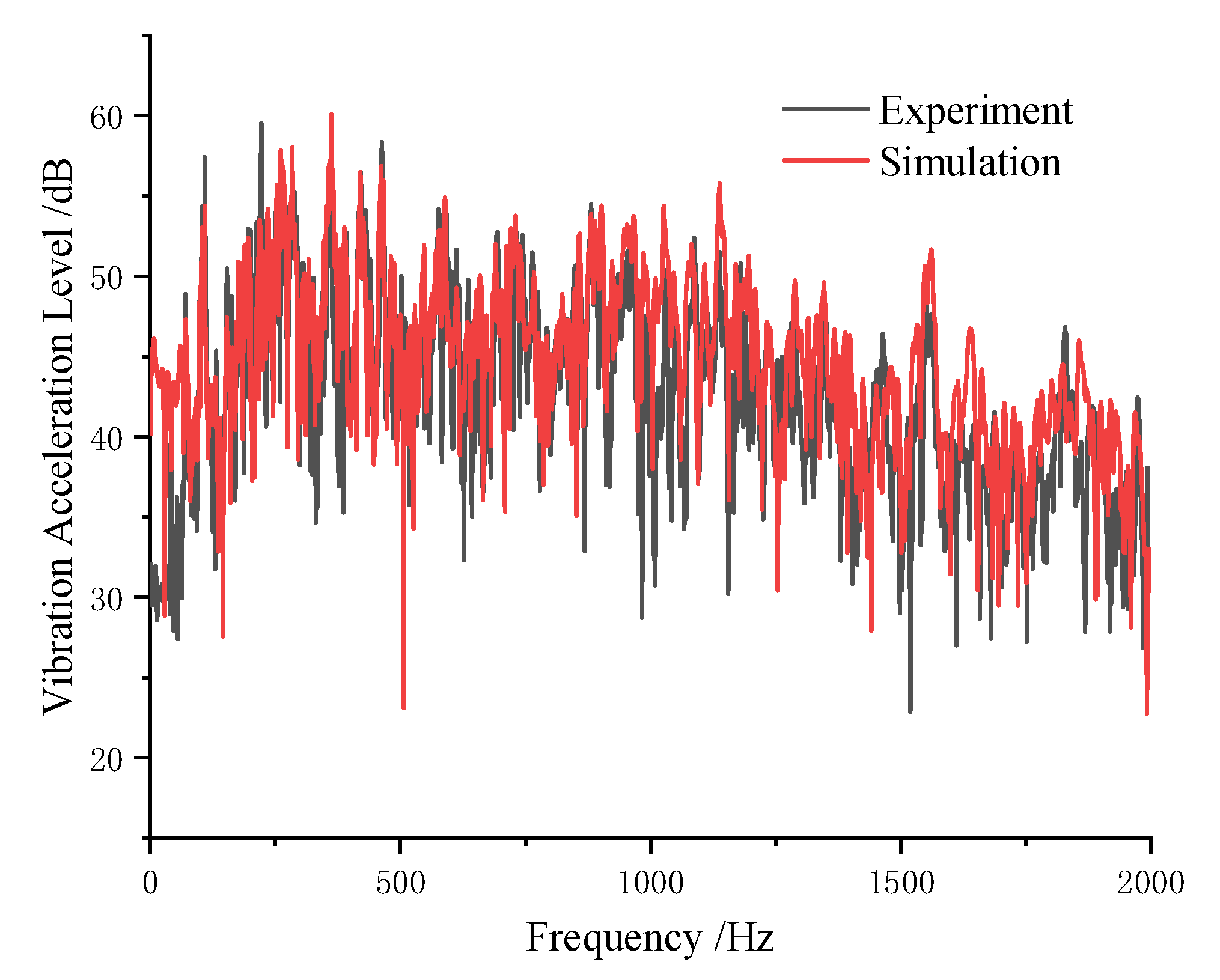
Figure 9 displays the comparative frequency-domain curves of vibration acceleration levels between experimental and numerical results at assessment point A7. Under transient impact excitation, the vibration energy distributes across a broad frequency band. The structural vibration response primarily exhibits dense line spectra at both the peak excitation frequency and natural frequencies, with particularly pronounced resonance occurring when these frequencies approach each other. As evident in the results, distinct peaks appear at 110 Hz and 260 Hz, among other frequencies, demonstrating good agreement between numerical simulations and experimental measurements.

3.5. Comparative Analysis of Transient Vibration Noise

Based on the structural dynamic response of the cylindrical shell obtained in Section 3.2 as boundary conditions, the transient sound radiation was calculated using the transient boundary element method (BEM). The numerical simulation results were then compared and validated against experimental measurements.
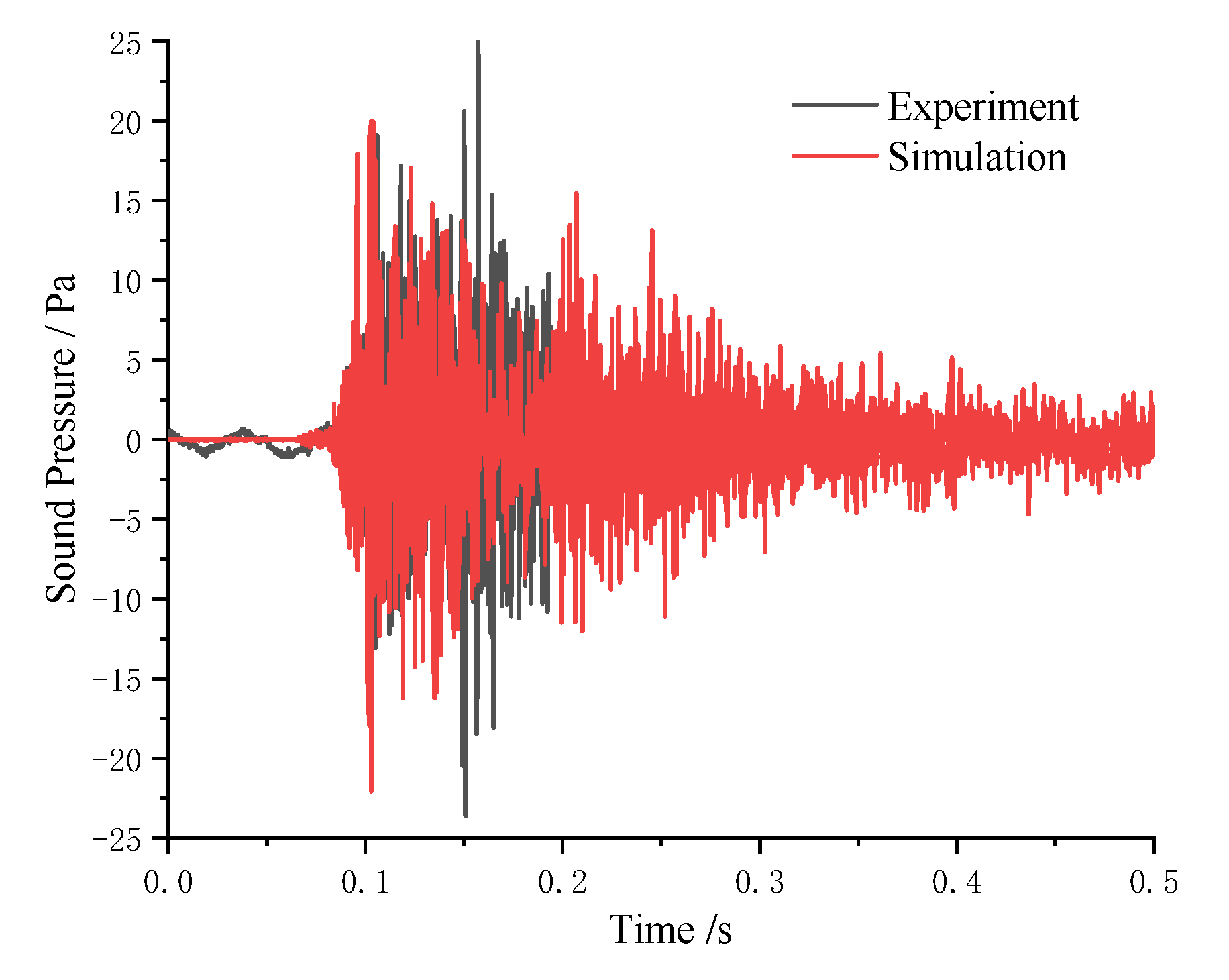
Figure 10 presents the comparative time-domain curves of acoustic pressure between experimental and numerical results at assessment point P1 during the initial 0.5-s period. Similar to the structural vibration trends, the underwater radiated noise pressure rapidly peaks shortly after pulse excitation loading. Following the pulse load cessation, the acoustic pressure decays swiftly. Notably, the time-domain numerical simulations of radiated noise at P1 exhibit excellent agreement with experimental measurements.
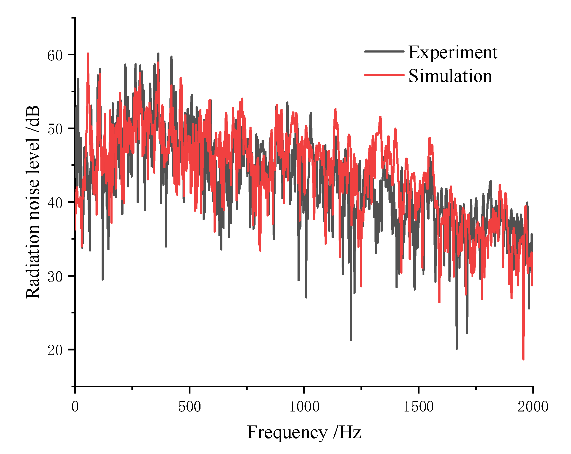
Figure 11 shows the frequency-domain comparison of sound pressure levels at P1. Under pulse excitation, the radiated noise energy distributes across a broad frequency band, with distinct peaks observed at 110 Hz, 260 Hz, and other frequencies. The numerically simulated sound pressure levels of the underwater stiffened cylindrical shell align closely with experimental data.

4. Analysis of Transient Vibro-Acoustic Characteristics of Double Stiffened Cylindrical Shell

4.1. Transient Impact Load and Working Condition Setting

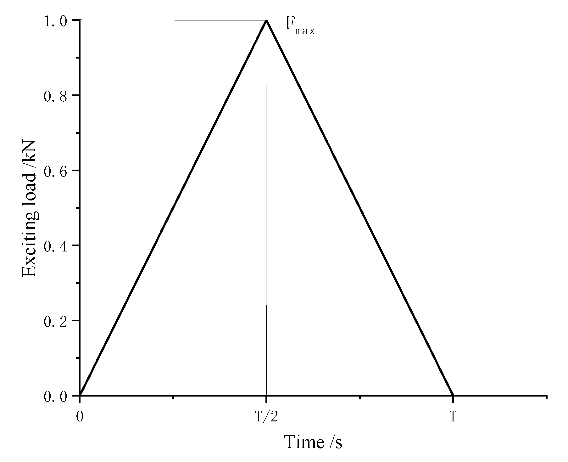
This study employs a finite element/boundary element (FEM/BEM) numerical method to investigate the transient vibration and acoustic radiation responses of the double-layered stiffened cylindrical shell under transient impact loading. Simply supported boundary conditions were applied at both ends of the cylindrical shell, and transient impact loads were simulated using triangular pulse loads at designated excitation points on the structure, as illustrated in Figure 12.
To examine the influence of pulse width and loading position of transient impact loads on the transient vibro-acoustic characteristics of the stiffened cylindrical shell, multiple case studies were conducted by varying both the pulse width (T) of transient impact loads and the loading positions, as specified in Table 2.

4.2. Modal Analysis of Double Stiffened Cylindrical Shell

The natural modes of a structure are fundamentally related to its vibration response, representing the most basic vibration characteristics. When a structure is subjected to an external force and undergoes forced vibration, this external force does not create vibration modes out of nothing; instead, it excites a series of the structure’s inherent natural modes. For the double-layered stiffened cylindrical shell model, transient loads may excite multiple structural modes, significantly influencing its vibro-acoustic radiation characteristics. Therefore, it is essential to clarify how these natural modes contribute to vibration and acoustic radiation. Since the vibration acceleration assessment points in this experiment are located on the inner shell, particular attention is given to the modal characteristics of the inner shell. High-frequency energy attenuates extremely rapidly, and consequently, high-frequency modes are typically difficult to excite. Therefore, the modal response of the double-layer stiffened cylindrical shell is calculated by the finite element simulation software, and the modal response of the structure in the low frequency band is mainly observed. The following diagram gives the three structural modal shape diagrams with the largest modal response, of which 116 Hz is the first-order overall bending of the structure, 256 Hz is the second-order axial bending of the structure, and 512 Hz is the local plate vibration of the structure. The inner shell vibration modes of the double-layer cylindrical shell mode at three frequencies are shown in Figure 13.

4.3. Transient Vibration Response Analysis of Double Stiffened Cylindrical Shell

Based on the transient impact load conditions specified in Section 4.1, the transient structural dynamics method was employed to solve for the vibration response induced by transient impact loads. The effects of different load pulse widths and loading positions on the vibration response of the stiffened cylindrical shell were then systematically analyzed.
(1)
Effect of Transient Load Pulse Width on Vibration Response of Stiffened Cylindrical Shell
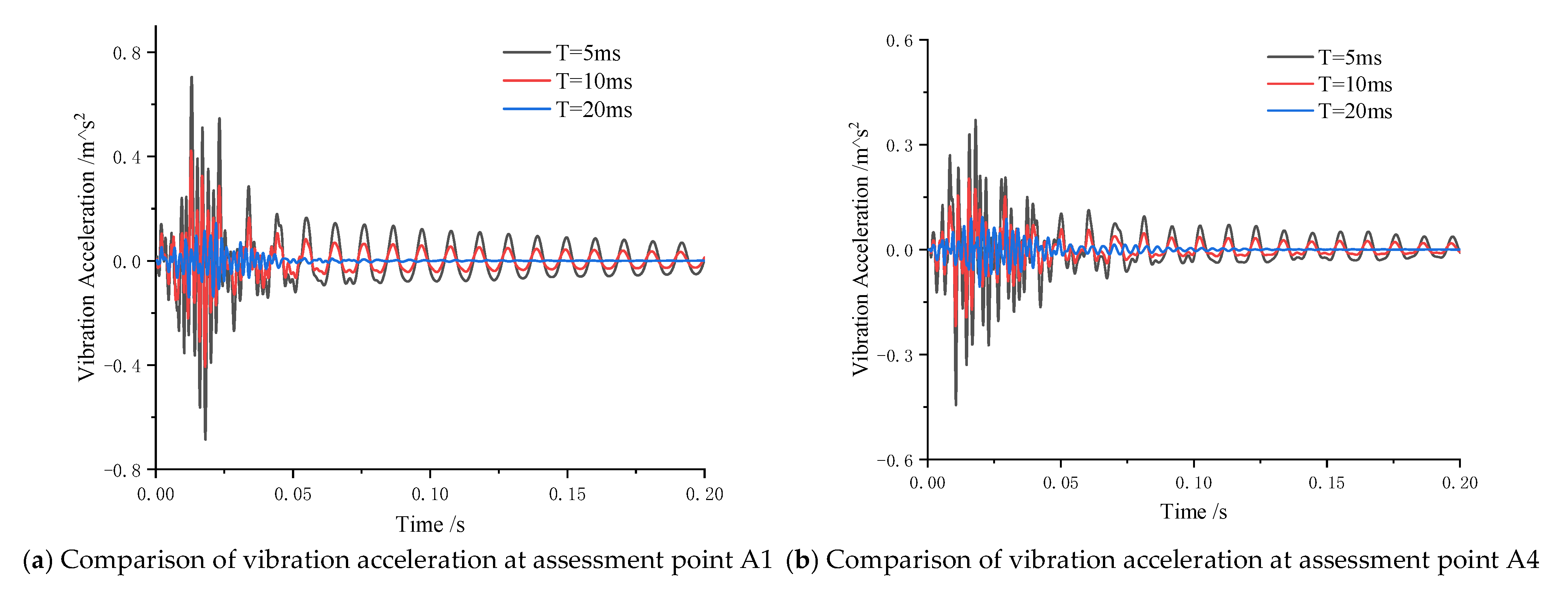
To investigate the effect of transient load pulse width on the vibration response of the stiffened cylindrical shell, a comparative analysis was conducted for Case 1 (T = 5 ms), Case 2 (T = 10 ms), and Case 3 (T = 20 ms). The resulting vibration accelerations of the double-layered stiffened cylindrical shell under these different pulse width conditions are presented in the figure below.
Figure 14 presents a comparison of time-domain vibration acceleration curves at assessment points A1 and A4 within the 0–0.20 s interval. The time-domain results demonstrate that under transient impact loading, the cylindrical shell’s vibration response exhibits pronounced fluctuations. The vibration acceleration initially increases rapidly, followed by damped free vibration after the pulse load ceases. The acceleration response shows a short-term growth trend, peaks, and then decays swiftly. Notably, when impact loads share equal peak magnitudes, shorter pulse widths result in less time for the vibration system to dissipate energy and mitigate the response, thereby yielding larger vibration amplitudes. Furthermore, the vibration acceleration at assessment point A1 (near the excitation location) significantly exceeds that at the contralateral point A4.
Time-frequency analyses were performed on the vibration accelerations at the two assessment points under the aforementioned three working conditions, with the results presented in the figure below.
It can be found from Figure 15 that there are some differences in the vibration response of the same assessment point under different working conditions. In addition, due to the different positions of the two assessment points, the stiffness of the area is also different, so there are some differences in the vibration components of the two assessment points.
Initial observations of the vibration responses at the two assessment points under different working conditions reveal that both points exhibit similar trends in response variation across varying pulse widths. Therefore, taking assessment point A1 as an example, the following characteristics can be noted: Under the three excitation load conditions, the peak vibration accelerations at point A1 predominantly occur near 110 Hz, 260 Hz, and 500 Hz. And there is a large structural modal response near the three frequencies, so it can be speculated that the peak value of structural vibration acceleration is related to the modal response of the structure. (see Figure 13). As the pulse width of the excitation load increases, the peak vibration acceleration at 100 Hz becomes less pronounced. This indicates that shorter pulse widths excite a broader range of the structural modes. Across all three working conditions, longer pulse widths result in a more prolonged decay of peak vibration responses, meaning the vibrational energy dissipates more slowly. This occurs because the amplitudes of the three excitation loads are identical. Consequently, a longer duration of the excitation force results in greater energy input into the structure. This increased energy requires a longer time to be dissipated by the system damping.
Under the same working conditions, the vibration responses of the two assessment points are further examined, and it is found that their dynamic behaviors have similar trends. Using the case with a 5 mm excitation pulse width as an example, the following observations can be made: The peak vibration response at assessment point A1 occurs at approximately 0.01 s, while the peak at assessment point A4 occurs at approximately 0.012 s. This time delay arises because point A1 is closer to the excitation source, and vibrational energy requires finite time to propagate outward. Comparing the vibration response of the two assessment points near 260 Hz and 500 Hz, it can be found that the structural vibration response energy of the assessment point A4 near the 260 Hz is more concentrated than that of the assessment point A1. This is due to the larger response of the 260 Hz structural mode at the assessment point A4. It can also be found that the vibration response of the structure lasts longer in the low frequency band (near 110 Hz). This is because the damping of the low frequency vibration mode is lower than that of the high frequency vibration mode, so the vibration energy of the high frequency band is partially consumed by the structural modal damping [32].
(2)
Influence of Transient Load Location on the Vibration Response of Stiffened Cylindrical Shells
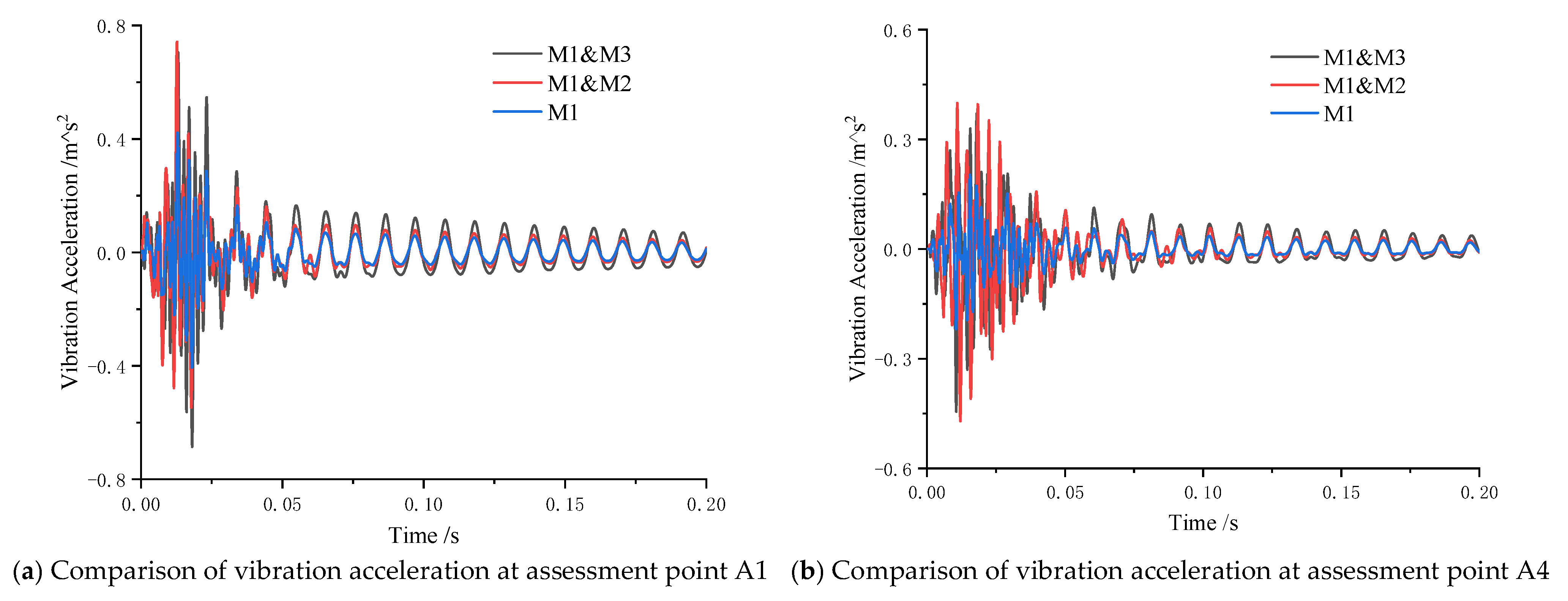
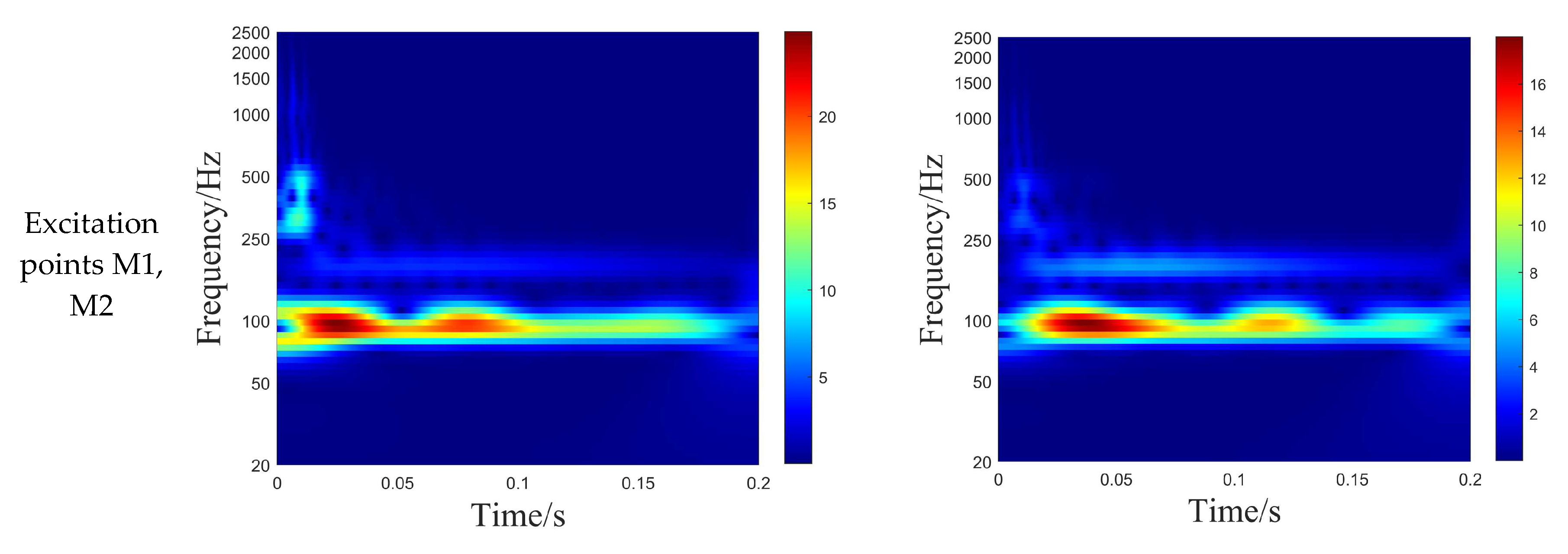
To investigate the influence of transient load location on the vibration response of stiffened cylindrical shells, a comparative analysis was conducted for working conditions 2, 4, and 5. The load parameters were held constant with a pulse width of T = 10 ms and amplitude of F = 1 kN, while the inner shell thickness was maintained at 0.01 m. Three loading configurations were examined: Single-point loading at M1; Simultaneous loading at M1 and M2 (located on the same side platform); Simultaneous loading at M1 and M3 (positioned on opposite side platforms).
Figure 16 presents the comparative time-domain vibration acceleration curves (0–0.20 s) and frequency-domain vibration acceleration level curves (0–2500 Hz) at assessment points A1 and A4. The time-domain results demonstrate that under transient impact loading, the time-history curves exhibit consistent trends across different loading locations, with the following key observations: The dual-point excitation case produces significantly larger vibration response amplitudes compared to single-point excitation. Moreover, it can be found that due to the more concentrated input energy of unilateral excitation, vibrational energy loss along the transmission path is lower than for bilateral excitation, so the peak value of structural vibration response caused by unilateral dual-point excitation is larger.
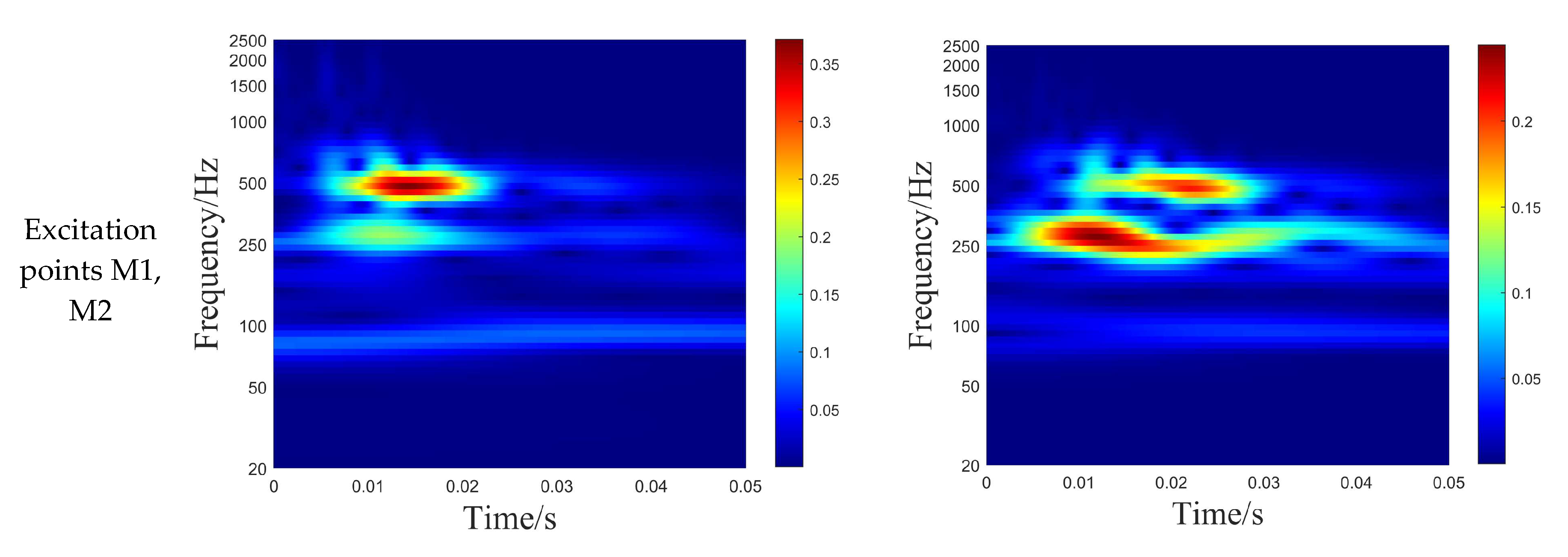
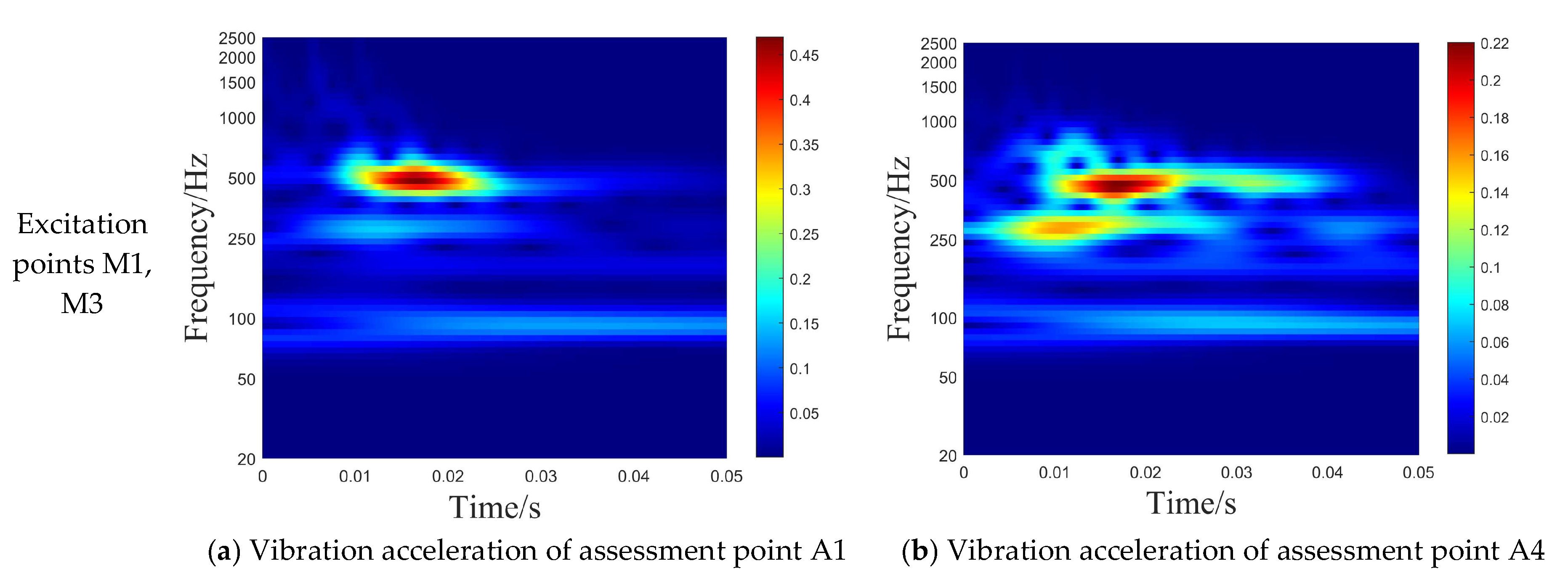
Analysis of Figure 17 can be found, due to the influence of structural modes, the vibration energy at both assessment points under the two working conditions is primarily concentrated near 110 Hz, 260 Hz, and 500 Hz. Compared with working condition 2 (single-point excitation), the following key observations emerge: Dual-point excitation produces significantly larger peak vibration responses than single-point excitation. This occurs because dual-point excitation inputs more energy than the single-point excitation input structure. The maximum response amplitude occurs when excitation points are M1 and M3 Excitation at M1 and M2 (same side) achieves peak response more rapidly. Same-side excitation more readily excites low-frequency vibration modes. This is because the spatial distribution of excitation forces applied on the same side resembles an overall eccentric moment loading. This distribution exhibits a high degree of matching with the mode shape of the low-order overall bending mode.

4.4. Transient Radiated Noise Analysis of Double-Layered Stiffened Cylindrical Shells

Based on the transient impact load conditions specified in Section 4.1, the radiated noise induced by transient excitation is calculated. A systematic investigation is conducted to analyze the influence of varying load amplitudes, pulse widths, and loading positions on the radiated noise characteristics of the double-layered stiffened cylindrical shell.
(1)
Influence of Transient Load Pulse Width on Radiated Noise of Stiffened Cylindrical Shell
To investigate the effect of transient load pulse width on the radiated noise of the stiffened cylindrical shell, a comparative analysis was conducted for Case 1 (T = 5 ms), Case 2 (T = 10 ms), and Case 3 (T = 20 ms). The radiated noise characteristics of the double-layered stiffened cylindrical shell under these conditions are illustrated in the figure below.
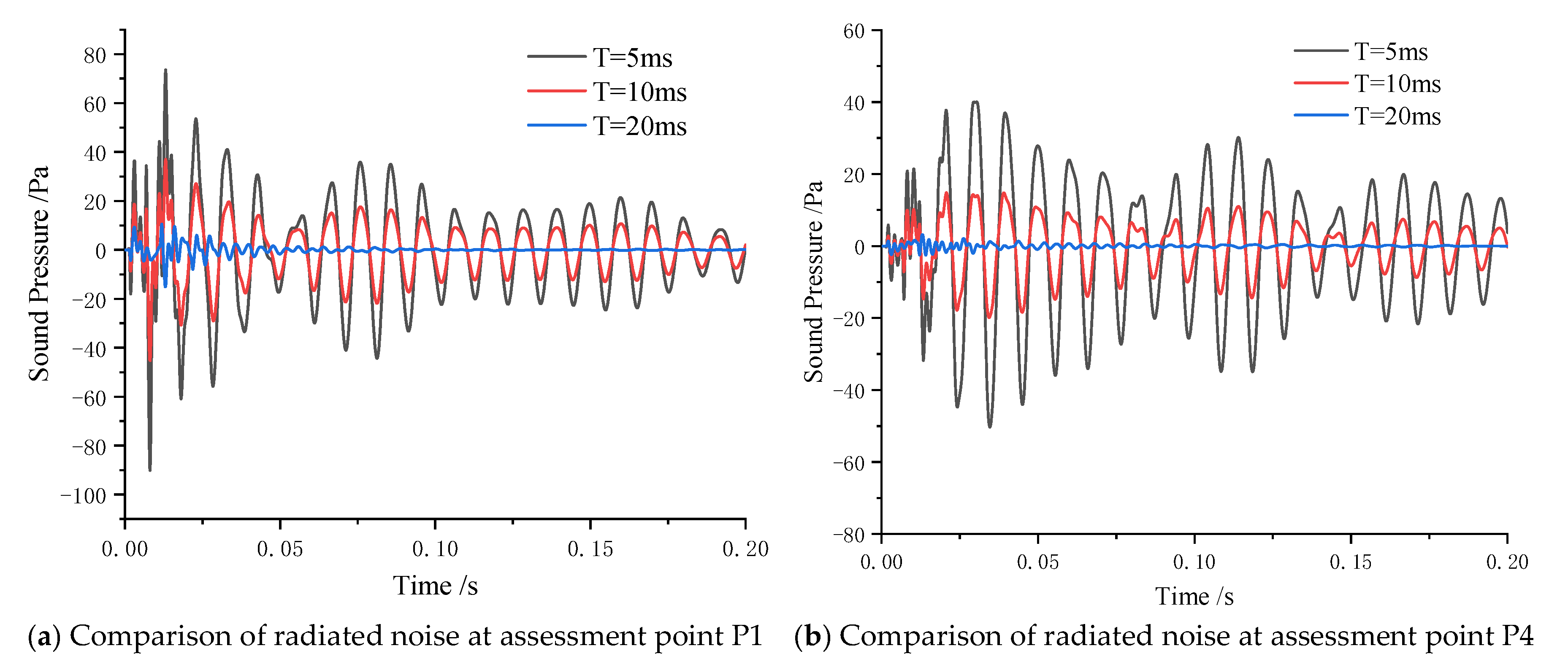
Figure 18 presents a comparison of time-domain radiated noise curves at assessment points P1 and P4 within the 0–0.20 s timeframe. The time-domain results reveal that under transient impact loads, the acoustic pressure at the assessment points undergoes pronounced fluctuations. The radiated noise initially increases rapidly, followed by a short-term growth trend after the pulse load vanishes. Upon reaching its peak, the noise decays swiftly. This is due to the existence of structural damping, resulting in continuous attenuation of vibration, which in turn leads to continuous attenuation of acoustic radiation. Notably, when the peak amplitudes of the impact loads are identical, a shorter pulse width leads to higher radiated noise levels. Because P1 is closer to the excitation point than P4, the acoustic transfer path is shorter and energy dissipation is reduced, so the radiation noise at P1 is larger than that at P4.
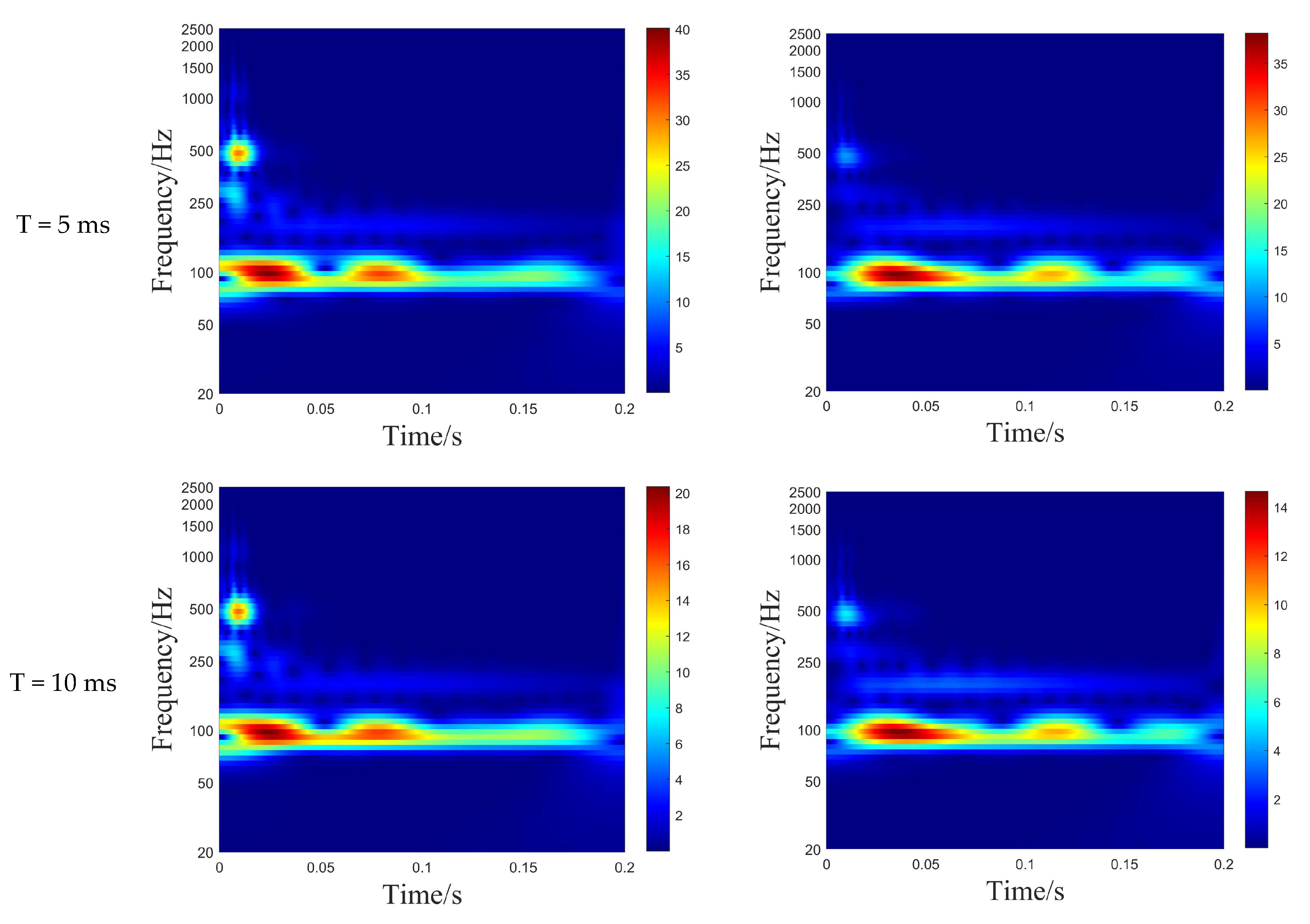
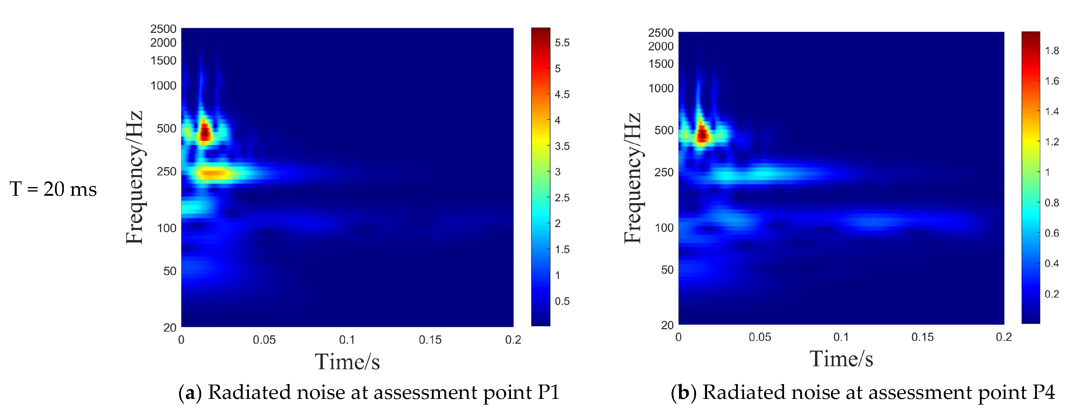
By comparing the time-frequency analysis plots of the two assessment points in the Figure 19, it can be observed that the noise components at both acoustic pressure assessment points are highly consistent with the aforementioned vibration components. The distribution of noise components closely matches that of vibration components, primarily concentrated around 110 Hz, 260 Hz, and 500 Hz. This phenomenon occurs because in transient boundary element calculations, the vibration characteristics of the structure directly determine the spectral features of the radiated noise. However, there are still differences between the spectral characteristics of radiated noise and vibration.
Similar to the vibration response, the smaller the pulse width of the excitation load, the more the radiated noise energy generated by the structure gathers in the low frequency band. However, unlike the structural vibration response, the radiated noise in the low-frequency band persists longer than that in the high-frequency band. This phenomenon is closely related to the propagation characteristics and attenuation mechanisms of acoustic waves in water. The absorption coefficient of sound waves increases significantly with frequency. Consequently, high-frequency sound waves experience faster attenuation loss during propagation in water.
(2)
Effect of Transient Load Position on Radiated Noise from Double-Layered Stiffened Cylindrical Shells
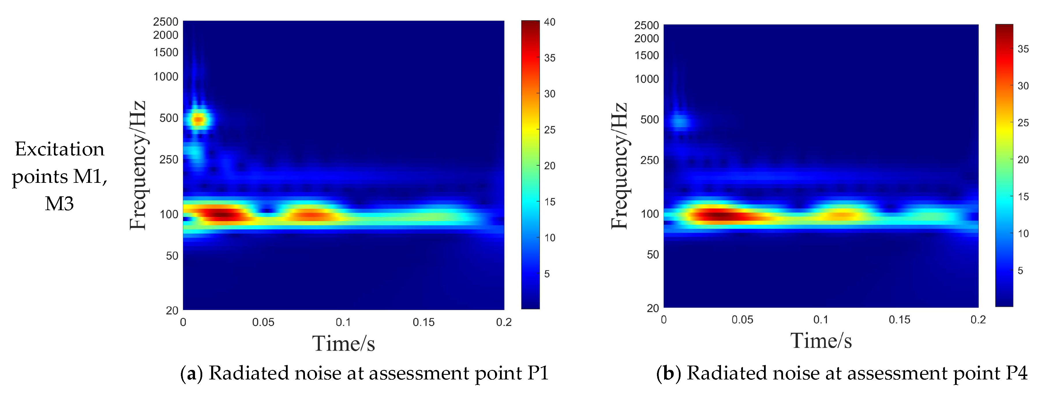
To investigate the influence of transient load position on the radiated noise of stiffened cylindrical shells, Cases 2, 4, and 5 were compared and analyzed. With a load pulse width of T = 10 ms, load amplitude of F max = 1 kN, and inner shell thickness of 0.01 m, the radiated noise induced under three loading configurations was examined: (1) single-point loading at M1, (2) simultaneous loading at M1 and M2, and (3) simultaneous loading at M1 and M3. The results are shown in the figure below.
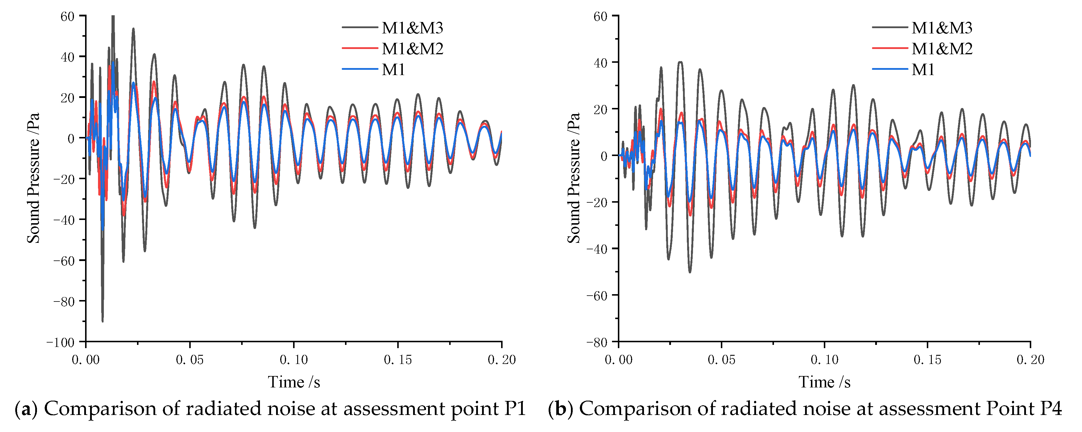
Figure 20 presents a comparison of radiated noise curves at assessment points P1 and P4 within the 0–0.20 s timeframe. The time-domain results demonstrate that under transient impact loading, the time-history curves exhibit consistent variation trends across different loading positions. Notably: The radiated noise amplitude under dual-point excitation significantly exceeds that of single-point excitation; The single-platform dual-excitation configuration achieves peak radiated noise more rapidly; The bilateral excitation configuration produces the maximum radiated noise amplitude.
In addition, it can be found that in the above five working conditions, the attenuation of the radiation noise generated by the structure is slower than the vibration response of the structure. This is due to the propagation of radiated noise in water, especially at low frequencies. The energy absorption loss efficiency of water is much smaller than that of solid due to structural damping.
As shown in Figure 21, analysis of the time-frequency diagrams of radiated noise at the assessment points under different working conditions reveals that, similar to the vibration response, the noise energy is primarily concentrated around 110 Hz, 260 Hz, and 500 Hz. Comparative analysis with Case 2 (single-point excitation) demonstrates that dual-point excitation generates significantly higher peak radiated noise levels. Specifically: The maximum radiated noise amplitude occurs when excitation points are M1 and M3 (opposite-side excitation); Excitation at M1 and M2 (same-side excitation) achieves peak noise levels more rapidly; Same-side excitation produces more pronounced energy aggregation in the low-frequency band. This is also because: the absorption coefficient of sound waves increases significantly with frequency. Consequently, high-frequency sound waves experience faster attenuation loss during propagation in water.

4.5. Transient Vibro-Acoustic Characteristic Analysis of Double-Layered Stiffened Cylindrical Shells

(1)
When impact loads share identical peak magnitudes, a shorter pulse width reduces the time available for the vibration system to dissipate energy and attenuate the response, resulting in larger vibration amplitudes.
(2)
The energy distribution of structural vibration responses correlates with the modality of the structure. The smaller the pulse width of the excitation load is, the more natural modes of the structure can be excited, and the local modes of the structure will also affect the vibration of the structure at the assessment point.
(3)
When excitation positions are bilaterally configured, the structure exhibits the maximum vibration response amplitude. Additionally, the vibration system requires a longer duration to dissipate energy and attenuate the response, while also more readily exciting low-frequency vibration modes.
(4)
Compared with the structural vibration response, the attenuation time of radiation noise is longer than that of structural vibration, and the duration of low-frequency radiation noise is longer than that of high-frequency radiation noise.

5. Conclusions

This study adopted an integrated experimental-numerical approach to investigate the underwater vibro-acoustic radiation characteristics of double-layered stiffened cylindrical shells. The principal findings are summarized as follows:
(1)
The vibration acceleration and sound pressure levels obtained from experimental measurements and numerical simulations show excellent agreement, thereby validating the accuracy and effectiveness of the time-domain finite element/boundary element (FEM/BEM) method employed in this study.
(2)
The vibro-acoustic radiation generated by double-layered stiffened cylindrical shells under transient impact loads exhibits distinct oscillatory characteristics, which are closely related to the structure’s inherent damping and natural modes.
(3)
Both the pulse width and loading position of transient impact loads influence structural vibro-acoustic radiation. The smaller the pulse width of the transient impact load, the more effectively it excites the natural modes of the structure, thereby affecting the resulting vibro-acoustic radiation. Similarly, when the spatial distribution of the excitation positions resembles the structure’s low-order mode shapes, it also more readily excites the low-order natural modes of the structure.
Building upon the developments and limitations identified in this study, future research could be undertaken in the following directions: investigating vibro-acoustic radiation characteristics for varying structural materials or load amplitudes, and exploring nonlinear effects in structural dynamics.

Author Contributions

Conceptualization, Q.L., W.M., C.G. and F.P.; methodology, Q.L., Z.Z., C.G. and F.P.; software, Q.L. and W.M.; validation, Q.L. and W.M.; formal analysis, Q.L.; investigation, Z.Z.; resources, Q.L. and W.M.; data curation, Q.L. and W.M.; writing—original draft preparation, Q.L. and W.M.; writing—review and editing, C.G. and F.P.; visualization, Q.L., W.M. and Z.Z.; supervision, C.G. and F.P.; project administration, C.G.; funding acquisition, C.G. All authors have read and agreed to the published version of the manuscript.

Funding

This study is funded by National Natural Science Foundation of China (52401368, 52471322).

Institutional Review Board Statement

Not applicable.

Informed Consent Statement

Not applicable.

Data Availability Statement

The data used to support the findings of this study are included within the article.

Conflicts of Interest

The authors declare that there is no conflict of interest regarding the publication of this paper.

References

  1. Pang, F.; Li, H.; Wang, X.; Miao, X.; Li, S. A semi analytical method for the free vibration of doubly-curved shells of revolution. Comput. Math. Appl. 2018, 75, 3249–3268. [Google Scholar] [CrossRef]
  2. Wang, X.; Chen, D.; Xiong, Y.; Wu, W. Simulation and investigations on the vibro-acoustic behavior of cylindrical shells in ice-covered water. Results Phys. 2019, 15, 102764. [Google Scholar] [CrossRef]
  3. Bonhage, M.; Adler, J.T.; Kolhoff, C.; Hentschel, O.; Schlesier, K.-D.; Panning-von Scheidt, L.; Wallaschek, J. Transient amplitude amplification of mistuned structures: An experimental validation. J. Sound Vib. 2018, 436, 236–252. [Google Scholar] [CrossRef]
  4. Lin, C.; Zou, M.; Jiao, H.; Liu, P. Identification of non-stationary excitation and analysis of transient radiation noise on steering engine. J. Ship Mech. 2016, 20, 758–767. [Google Scholar]
  5. Kingan, M.J.; Yang, Y.; Mace, B.R. Sound transmission through cylindrical structures using a wave and finite element method. Wave Motion 2019, 87, 58–74. [Google Scholar] [CrossRef]
  6. Manconi, E.; Mace, B.R.; Garziera, R. Wave propagation in laminated cylinders with internal fluid and residual stress. Appl. Sci. 2023, 13, 5227. [Google Scholar] [CrossRef]
  7. Ross, A.; Ostiguy, G. Propagation of the initial transient noise from an impacted plate. J. Sound Vib. 2007, 301, 28–42. [Google Scholar] [CrossRef]
  8. Li, J.; Shi, Z.; Liu, L.; Song, C. An efficient scaled boundary finite element method for transient vibro-acoustic analysis of plates and shells. Comput. Struct. 2020, 231, 106211. [Google Scholar] [CrossRef]
  9. Aimi, A.; Desiderio, L.; Di Credico, G. Partially pivoted ACA based acceleration of the energetic BEM for time-domain acoustic and elastic waves exterior problems. Comput. Math. Appl. 2022, 119, 351–370. [Google Scholar] [CrossRef]
  10. Gao, Z.; Li, Z.; Liu, Y. A time-domain boundary element method using a kernel-function library for 3D acoustic problems. Eng. Anal. Bound. Elem. 2024, 161, 103–112. [Google Scholar] [CrossRef]
  11. Takahashi, T.; Tanigawa, M.; Miyazawa, N. An enhancement of the fast time-domain boundary element method for the three-dimensional wave equation. Comput. Phys. Commun. 2022, 271, 108229. [Google Scholar] [CrossRef]
  12. Chen, Z.; Wang, A.; Qin, B.; Wang, Q.; Zhong, R. Investigation on free vibration and transient response of functionally graded graphene platelets reinforced cylindrical shell resting on elastic foundation. Eur. Phys. J. Plus 2020, 135, 582. [Google Scholar] [CrossRef]
  13. Liu, C.-C.; Li, F.-M.; Chen, Z.-B.; Yue, H.-H. Transient wave propagation in the ring stiffened laminated composite cylindrical shells using the method of reverberation ray matrix. J. Acoust. Soc. Am. 2013, 133, 770–780. [Google Scholar] [CrossRef] [PubMed]
  14. Dalton, E.; Burton Chambers, N.S.I.; Chambers, N.S.I. Analysis and validation testing of impulsive load response in complex, multi-compartmented structures. In Proceedings of the 36th Structures, Structural Dynamics and Materials Conference, New Orleans, LA, USA, 10–13 April 1995; p. 1243. [Google Scholar]
  15. Zou, M.-S.; Peng, S.-L.; Yang, Y.-N.; Liu, Y. Time-domain calculation method for sound radiation of underwater vehicles strictly coupled with nonlinear floating raft isolation system. Thin-Walled Struct. 2025, 216, 113662. [Google Scholar] [CrossRef]
  16. Shi, Y.; Yang, D.; Li, Q. Underwater radiated noise numerical analysis of polar transport vessels under ship-ice-water-air coupling continuous icebreaking based on the S-ALE algorithm. Ocean Eng. 2024, 309, 118511. [Google Scholar] [CrossRef]
  17. Menton, R.T.; Magrab, E.B. Farfield radiation of internally generated transient acoustic pulses transmitted through a spherical shell. J. Acoust. Soc. Am. 1974, 55, 237–246. [Google Scholar] [CrossRef]
  18. Chappell, D.; Harris, P.; Henwood, D.; Chakrabarti, R. Transient acoustic radiation from a thin spherical elastic shell. In Integral Methods in Science and Engineering: Techniques and Applications; Birkhäuser: Boston, MA, USA, 2008; pp. 47–54. [Google Scholar]
  19. Christoforou, A.P.; Swanson, S. Analysis of simply-supported orthotropic cylindrical shells subject to lateral impact loads. J. Appl. Mech. 1990, 57, 376–382. [Google Scholar] [CrossRef]
  20. Hoai, L.; Tu, P.H.; Tran, V.K.; Hue, N.T. An isogeometric approach for vibration characteristics analysis of functionally graded triply periodic minimal sandwich curved-doubly shell integrated with magneto-electro surface layers subjected to low-velocity impact load. Def. Technol. 2025, 50, 101–125. [Google Scholar] [CrossRef]
  21. Pandey, A.M.; Gopal, K.N. Transient vibration and sound radiation analysis of simply supported functionally graded sandwich plates. Compos. Struct. 2022, 290, 115520. [Google Scholar] [CrossRef]
  22. Liu, J.; Hao, C.; Ye, W.; Yang, F.; Lin, G. Free vibration and transient dynamic response of functionally graded sandwich plates with power-law nonhomogeneity by the scaled boundary finite element method. Comput. Methods Appl. Mech. Eng. 2021, 376, 113665. [Google Scholar] [CrossRef]
  23. Chappell, D.; Harris, P.; Henwood, D.; Chakrabarti, R. A stable boundary element method for modeling transient acoustic radiation. J. Acoust. Soc. Am. 2006, 120, 74–80. [Google Scholar] [CrossRef]
  24. Geng, L.; Chen, X.-G.; He, S.-P.; He, C.-D. Reconstruction of transient acoustic field using sparse real-time near-field acoustic holography. J. Sound Vib. 2024, 568, 117973. [Google Scholar] [CrossRef]
  25. Chen, Q.; Fei, Q.; Wu, S.; Li, Y. Transient energy response analysis of vibro-acoustic systems with fuzzy uncertainty. J. Aircr. 2021, 58, 210–215. [Google Scholar] [CrossRef]
  26. Li, Q.; Wang, Z.; Li, L.; Hao, H.; Chen, W.; Shao, Y. Machine learning prediction of structural dynamic responses using graph neural networks. Comput. Struct. 2023, 289, 107188. [Google Scholar] [CrossRef]
  27. Hu, Y. Underwater transient signal detection under two noise reduction methods. In Proceedings of the 2024 IEEE 4th International Conference on Electronic Technology, Communication and Information (ICETCI), Changchun, China, 24–26 May 2024; pp. 929–932. [Google Scholar]
  28. Yu, T.-k.; Liu, W.-s.; Shi, S.-g.; Long, J. Measurement and assessment method for ship radiating transient noise. In Proceedings of the 2017 2nd International Conference on Automation, Mechanical Control and Computational Engineering (AMCCE 2017), Beijing, China, 25–26 March 2017; pp. 215–225. [Google Scholar]
  29. Yu, T.; Xiong, C.; Wang, X.; Dai, X.; Xuefeng, T. Rapid acquisition method of sea vessel radiating transient noise effective time based on the power-law. In Proceedings of the 2nd International Conference on Mechatronics Engineering and Information Technology (ICMEIT 2017), Dalian, China, 13–14 May 2017; pp. 507–514. [Google Scholar]
  30. Leissing, T.; Audoly, C.; Lachambre, H.; Stempfel, G. Advanced signal processing methods for the analysis of transient radiated noise from submarines. In Proceedings of the INTER-NOISE and NOISE-CON Congress and Conference Proceedings, Melbourne, Australia, 16–19 November 2014; pp. 852–861. [Google Scholar]
  31. Gao, C.; Zhang, H.; Li, H.; Pang, F.; Wang, H. Numerical and experimental investigation of vibro-acoustic characteristics of a submerged stiffened cylindrical shell excited by a mechanical force. Ocean Eng. 2022, 249, 110913. [Google Scholar] [CrossRef]
  32. Tonazzi, D.; Meziane, A.; Culla, A.; Biateau, C.; Pepe, G.; Massi, F. Material Damping Estimation within Low-, Medium-and High-Frequency Ranges. Int. J. Appl. Mech. 2024, 16, 2450056. [Google Scholar] [CrossRef]
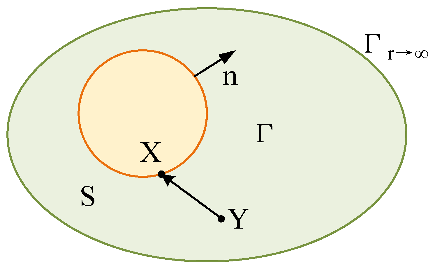
Figure 1. Solution domain of sound field by boundary element method.
Acoustics 07 00050 g001
Figure 2. Flow chart.
Acoustics 07 00050 g002
Figure 3. Test verification model and geometric model of double cylindrical shell.
Acoustics 07 00050 g003
Figure 4. Load excitation point.
Acoustics 07 00050 g004
Figure 5. Measured pulse load.
Acoustics 07 00050 g005
Figure 6. Vibration acceleration and sound pressure assessment points.
Acoustics 07 00050 g006
Figure 7. Structural finite element and acoustic boundary element models.
Acoustics 07 00050 g007
Figure 8. Comparison of time-domain vibration acceleration of assessment point A7.
Acoustics 07 00050 g008
Figure 9. Comparison of frequency domain vibration acceleration of assessment point A7.
Acoustics 07 00050 g009
Figure 10. Comparison of P1 time-domain radiation noise at assessment point.
Acoustics 07 00050 g010
Figure 11. Comparison of P1 frequency domain radiation noise at assessment point.
Acoustics 07 00050 g011
Figure 12. Impact load diagram.
Acoustics 07 00050 g012
Figure 13. Inner shell modal response diagram.
Acoustics 07 00050 g013
Figure 14. Vibration response of the double-layered stiffened cylindrical shell under different transient impact load pulse widths.
Acoustics 07 00050 g014
Figure 15. Time-frequency analysis of the vibration response of the double-layered stiffened cylindrical shell under transient impact loads with varying pulse widths.
Acoustics 07 00050 g015
Figure 16. Vibration Response of the Stiffened Cylindrical Shell Under Different Transient Load Locations.
Acoustics 07 00050 g016
Figure 17. Time-frequency analysis of vibration response for the stiffened cylindrical shell under different transient load locations.
Acoustics 07 00050 g017aAcoustics 07 00050 g017b
Figure 18. Radiated Noise of Double-Layered Stiffened Cylindrical Shell Under Different Transient Impact Pulse Widths.
Acoustics 07 00050 g018
Figure 19. Time-frequency analysis of radiated noise from the double-layered stiffened cylindrical shell under different transient impact load pulse widths.
Acoustics 07 00050 g019aAcoustics 07 00050 g019b
Figure 20. Radiated Noise of Double-Layered Stiffened Cylindrical Shell under different transient load positions.
Acoustics 07 00050 g020
Figure 21. Time-frequency analysis of Radiated Noise for the stiffened cylindrical shell under different transient load locations.
Acoustics 07 00050 g021aAcoustics 07 00050 g021b
Table 1. Main parameters of double stiffened cylindrical shell.
ParameterNumerical Value (m)
Shell radius0.75
Inner shell radius0.63
Model length2.0
Shell thickness0.01
Inner shell thickness0.01
Ring rib section a × b0.01 × 0.008
Ring rib spacing0.4
Table 2. Working Condition Setting.
Condition NumberLoad
Amplitude (N)
Load Pulse Length(ms)Loading
Position
Inner Shell Thickness (m)Vibration
Acceleration Measuring Point Position
Sound Field Assessment Point Position
mode 110005M10.01A1, A4P1, P4
mode 2100010M10.01A1, A4P1, P4
mode 3100020M10.01A1, A4P1, P4
mode 4100010M1, M20.01A1, A4P1, P4
mode 5100010M1, M30.01A1, A4P1, P4
Disclaimer/Publisher’s Note: The statements, opinions and data contained in all publications are solely those of the individual author(s) and contributor(s) and not of MDPI and/or the editor(s). MDPI and/or the editor(s) disclaim responsibility for any injury to people or property resulting from any ideas, methods, instructions or products referred to in the content.