Article

Applicability of Aeroacoustic Scaling Laws of Leading Edge Serrations for Rotating Applications

1
Institute of Sound and Vibration Engineering ISAVE, University of Applied Sciences, D-40476 Dusseldorf, Germany
2
Institute of Fluid Dynamics and Technical Acoustics ISTA, Technical University of Berlin, D-10623 Berlin, Germany
*
Author to whom correspondence should be addressed.
Acoustics 2020, 2(3), 579-594; https://doi.org/10.3390/acoustics2030030
Submission received: 19 June 2020 / Revised: 18 July 2020 / Accepted: 21 July 2020 / Published: 23 July 2020
(This article belongs to the Special Issue Aeroacoustics of Turbomachines)

Abstract

:
The dominant aeroacoustic mechanisms of serrated leading edges, subjected to highly turbulent inflow conditions, can be compressed to spanwise decorrelation effects as well as effects of destructive interference. For single aerofoils, the resulting broadband noise reduction is known to follow spectral scaling laws. However, transferring serrated leading edges to rotating machinery, results in noise radiation patterns of significantly increased complexity, impeding to allocate the observed noise reduction to the underlying physical mechanisms. The current study aims at concatenating the scaling laws for stationary aerofoil and rotating-blade application and thus at providing valuable information on the aeroacoustic transferability of leading edge serrations. For the pursued approach, low-pressure axial fans are designed, obtaining identical serrated fan blade geometries than previously analyzed single aerofoils, hence allowing for direct comparison. Highly similar spectral noise reduction patterns are obtained for the broadband noise reduction of the serrated rotors, generally confirming the transferability and showing a scaling with the geometrical parameters of the serrations as well as the inflow conditions. Continuative analysis of the total noise reduction, however, constrains the applicability of the scaling laws to a specific operating range of the rotors and motivates for a devaluation of the scaling coefficients regarding additional rotor-specific effects.

1. Introduction

For the single aerofoils under highly turbulent inflow conditions, the approaching turbulent structures cause pressure fluctuations that propagate as acoustic waves into the far-field [1], resulting in broadband noise radiation [2]. This broadband noise, mainly stemming from the leading edge of an aerofoil, can be drastically reduced by implementing a leading edge pattern of sinusoidal shape [3,4,5], called leading edge serrations. The general shape of these serrations is usually parametrized by the serration amplitude A and the serration wavelength λ (Figure 1), where the wavy shape of the serrations mainly results in three effects [6]. First, a cut-off of the acoustic sources along the oblique edges of the serrations [7,8,9], leading to weaker acoustic sources. Second, decorrelation effects [3,10] along the span of the aerofoil lead to reduced radiation due to phase differences. Eventually, the third effect can be attributed to destructive interference between the serration peak and the root region [3,7,11], leading to an extensive decrease of noise at frequencies where the acoustic wavelength corresponds to the size of the serration amplitude. A majority of the available studies concerning serrated leading edges were carried out based on single stationary aerofoils [4,7,12], even though the final application area is considered to be turbomachines, fans and blowers, or contra-rotating rotors, where only little research was carried out [13,14,15]. However, considering the acoustic sources of rotating machinery, it becomes apparent, that multiple additional noise sources are present (Figure 1). These include among others (a) effects in the blade tip region due to interaction of the rotating blades and the reverse flow, (b) noise due to secondary flows such as separated vortical structures interacting with subsequent blades, and (c) rotor–stator interaction noise. This already complex aeroacoustic pattern is bedevilled by radius-dependent inflow conditions of the blades in terms of the circumferential velocity (and turbulence conditions) as well as varying inflow angles as a function of the fans’ throttling state or operation point, respectively. Consequently, even at highly turbulent inflow conditions, the leading edge broadband noise not necessarily needs to represent the dominant noise source since it can be masked by the aforementioned additional effects of tonal and/or broadband character. Hence, when implementing leading edge serrations in rotating systems, the developer needs to deal with various effects, not yet considered for the single aerofoil investigations. To describe the transferability of serrated leading edges, the current study focuses on directly comparing the aeroacoustic effect of leading edge serrations for the single aerofoils and rotating machinery through low-pressure axial fans. The basic idea of the present study is to analyze the aeroacoustic noise reduction potential of single stationary NACA 65(12)-10 aerofoils, which are also commonly used for rotating applications. In a second step, the identical aerofoil type, including the leading edge serrations, is scaled and employed for the design of low-pressure axial fans, enabling a direct comparison between the two considered systems.
Figure 1 serves to emphasize the increased complexity of the acoustic pattern when comparing a full rotor to an isolated stationary aerofoil at comparable operation conditions, which include (a) comparable inflow angles, (b) an identical aerofoil/blade geometry, and (c) comparable inflow conditions using U0 and the turbulence intensity Tu.
As it is indicated by the grey hatching in Figure 1, the radiated noise increases significantly at inflow conditions of elevated turbulence. In reverse conclusion, this low-to-mid-frequency region characterizes the maximum noise reduction potential when implementing e.g., serrated leading edges or any other device affecting the radiation of turbulence-ingested leading edge noise.
Speaking of broadband noise reduction due to leading edge serrations, the spectral sound power level reduction ΔPWL (Equation (6)) is obtained by subtracting the acoustic signature of a serrated aerofoil PWLSerr from that of an aerofoil with a straight leading edge PWLBSLN. For isolated stationary aerofoils, the resulting spectral noise reduction is known to continuously increase from low to high frequencies [6,17], where the maximum is reached at the point of intersection, at which aerofoil self-noise due to the turbulent boundary layer starts to become increasingly dominant, forcing a decreasing performance for frequencies beyond this point. On this basis, a recent study by Chaitanya et al. [6], extending initial studies by Kim et al. [7], provides a rudimentary scaling law by which the spectral noise reduction ΔPWL is stated to follow Equation (1), with the prefactor generally being as = 10. The upper limit of the possible noise reduction can be achieved with bs = 10 at an optimum ratio of serration wavelength and transversal turbulence length scale λ/Λt ≥ 4 and takes place in the low-to-intermediate frequency range in the form of the amplitude-based Strouhal number SrA. Note that even though both constants as and bs define the maximum noise reduction capability, the prefactor as controls the slope of the trends, whereas bs controls the parallel shift of the noise reduction:
Δ P W L = P W L B S L N P W L S e r r = a S · l g ( S r A ) + b S   w i t h     S r A = f · A U 0 .
Continuatively, the current study aims at answering the question if and how these aeroacoustic scaling laws also apply in the rotating context. This is of importance since it assists in assigning the causative mechanisms of the noise reduction for the tested rotors to the known mechanisms at isolated aerofoils. In a more general context, this analysis is expected to provide valuable information in assessing if the already known effects assigned to leading edge serrations still play the key role in reducing rotor noise or if there are effects that are more prominent.
Prior extracting the spectral scaling in the rotating domain, a valid data basis for isolated aerofoils of the identical geometric design was generated by Biedermann et al. [18], who performed aeroacoustic (and aerodynamic) characterization of the chosen NACA 65(12)-10 aerofoils via an extensive aeroacoustic beamforming study. The main advantage of this specific setup, however, is the possibility to exclude all the unwanted and distracting noise sources stemming from the aerofoil trailing edge, the open jet, the turbulence grids installed or even from the turbulent boundary layer. More recently, a similar approach was also followed by Bampanis et al. [19] for flat plate aerofoils, differentiating between the spectral contributions of leading edge noise and trailing edge noise.
For the current study, testing serrated aerofoils of varying serration amplitude A and serration wavelength λ by comparing the spectral noise composition to a straight leading edge baseline aerofoil, results in the spectral noise reduction pattern ΔPWL shown in Figure 2. Generally, the proposed spectral scaling law can be confirmed, even though higher prefactors of as = 15 according to Equation (1) are obtained, which can be attributed to the absence of aerofoil self-noise, usually attenuating the maximum noise reduction in the mid-frequency SrA-range. The upper limits of noise reduction are obtained at maximum amplitudes (bs = 8.5) and minimum wavelengths (bs = 10) [18]. Most interestingly, the optimum λ/Λt-ratio defined by Chaitanya et al. [3,6] is λ/Λt ≈ 2 for maximum decorrelation effects and λ/Λt ≈ 4 for maximum interference effects, enclosing the observed optimum of λ/Λt = 2.6 in Figure 2.

2. Materials and Methods

To make first steps towards rotating applications, a test rig (Figure 3a) according to the ISO 5136 standard [20] was developed which allows for simultaneous characterization of the aerodynamic and aeroacoustic performance of low-pressure axial fans with and without leading edge serrations. The rotor is designed according to the isolated aerofoil approach [21], where the NACA 65(12)-10 fan blades are twisted in the spanwise direction to meet optimum incidence for all circumferential sections at design conditions. The test rig, as well as the data acquisition procedure, is identical to previous studies by the authors and is described more detailed in [22,23]. However, the focus of the present as well as of previous studies is to provide a low-speed axial fan of minimum complexity, which, in reverse conclusion, allows analyzing and identifying the net-noise-reduction potential of serrated blades in the rotating frame. Therefore, complex blade geometries such as blade skew and blade dihedral are intentionally avoided.
Implementing coarse biplane square grids [24] upstream of the rotor allows to vary the level of the incoming turbulence in a range of 2.6% ≤ Tu ≤ 12.1% for the rotor plane, where the mean longitudinal velocity U0 serves as the denominator of the turbulence intensity Tu to remain independent of the tested rotor design. Excessive preliminary measurements via hot wire anemometry were carried out by employing a rotating duct and the hot wire anemometry [22], resulting in the spatial velocity distribution for the rotor plane as can be seen from Figure 4. Circumferential averaging of the data obtained leads to more general profiles of the incoming Tu, the longitudinal velocity as well as the transversal integral length scale ΛT (Figure 4b), making apparent the strong influence of the duct boundary layer on the resulting profiles. Representative single number values are obtained by averaging over a radius of RDuct = 0.15 m to neglect influences of the wall boundary layer (Figure 4a). Preliminary studies on the power spectral density of the turbulent energy [23] showed it to scale-well with the turbulent cascade theory [25], resulting in scaling with f−5/3 in the inertial range and with f−7 in the dissipation range. Deviations from the model are, once again, observed close to the duct wall, though generally proving the turbulence conditions being of near-isotropic nature.
For the design of the serrated leading edges, the maximum chord C of the blades was kept constant, resulting in different amplitude-dependent wetted surfaces of the fan blades as can be seen in Figure 5. An alternative approach would be to keep the mean chord constant, resulting in an extension of the local blade chord by A/2. The choice for the former design approach mainly serves three reasons:
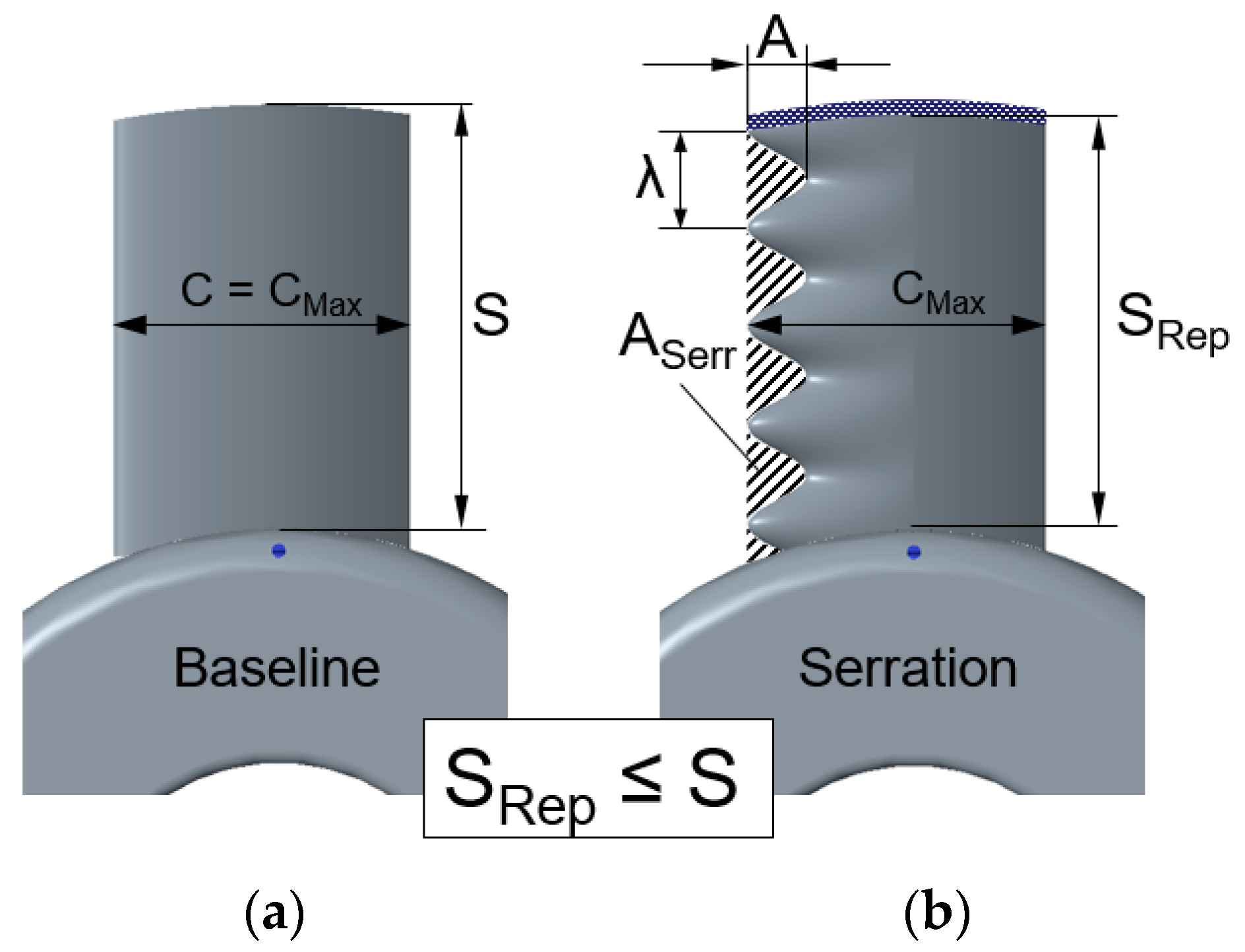
  • A constant maximum blade chord results in only one baseline reference case for comparison as well as in a constant blade thickness for different serration geometries.
  • Keeping constant maximum solidity σS prevents amplitude-dependent interaction effects of successive blades at solidities σS ≥ 0.7.
  • Pursuing a conservative approach that remains close to practical applications, in which serrations might be included as a substituting technology at limited installation space by simply replacing previously mounted straight blades.
The aerodynamic performance is described via the non-dimensional flow coefficient φ in Equation (2) and the pressure coefficient ψ (Equation (3)) at iso-speed n = 2000 min−1. Note that due to the specific setup and the location of the pressure sensors, the pressure coefficient ψ is defined by the static pressure rise Δp and the grid-dependent pressure loss ΔpGrid (compare Figure 3a). The efficiency of the fan assembly ηSystem in Equation (4) eventually serves to describe the relation of electric demand Pel vs. the aerodynamic output Paero. The small amplitude-dependent differences in the blade surface area (see Figure 5) naturally affect the aerodynamic performance in terms of static pressure rise Δp as well as the flow rate Q ˙ . For comparison purposes, these differences require compensation. In contrast to the coefficients of lift and drag, for which a normalization by the wetted surface takes place for single aerofoils, the flow and pressure coefficients of rotating machines offer no such compensation mechanisms. Therefore, preliminary measurements for straight blades of a varying chord are carried out by testing three different rotors with straight leading edges [23]. The surface of the three sets of rotor blades equals the wetted surface of the serrated blades with maximum (C/C0 = 0.83), intermediate (C/C0 = 0.91), and no (C/C0 = 1) serration amplitude. Testing these scaled baseline blades, instead of the serrated blades, prevents including possible flow-dependent effects of leading edge serrations, which might affect the flow rate or the pressure rise.
The results shown in Figure 6 indicate the (wetted) surface of the blades to contribute linearly to the static pressure rise Δp. The individual share of each semi-infinite radial element, however, scales with the circumferential velocity Urot (Urot*) in Equations (2) and (3), where the required rotor diameter is defined by the hub diameter DHub plus the (representative) blade span S (SRep). Consequently, the circumferential velocity Urot of the pressure coefficient ψ (Equation (3)) is defined according to an area-equivalent blade span SRep (Equation (3) and Figure 5), which is a function of the removed serration area ASerr (Equation (5)) from the initial blade area ABlade:
φ = Q ˙ U r o t · ( A B l a d e A S e r r / 2 ) ,   U r o t = π · n · ( D H u b + 2 · S ) ,
ψ = ( Δ p + Δ p G r i d ) / ρ U r o t 2 * / 2 ,   U r o t * = π · n · ( D H u b + 2 · S R e p ) ,   S R e p = S · C A S e r r C ,
η s y s t e m = P a e r o   P e l = Δ p · Q ˙ U e l · A e l ,
A S e r r = 2 S λ 0 π A · s i n ( 2 π / λ · x )   d x .
In terms of acoustics, a microphone arrays at the discharge side of the fan unit enables gathering reliable and stable data, non-affected by the grid self-noise on the suction side. This array consists of three one-quarter inch wall-mounted condenser microphones, distributed circumferentially at the duct wall. Note that no beamforming is applied to the rotating application but that the spectral average of the microphone signals is used for further processing towards the local sound pressure level SPL (Equation (6)) with pRMS being the effective sound pressure of the gathered signals and p0 the reference value by means of the human threshold of audibility at 1 kHz. Continuatively, the overall sound pressure level OASPL is defined according to Equation (7) in the given frequency band 10 Hz ≤ f ≤ 10 kHz. Eventually, normalization by the enveloping surface of the noise sources AE as well as compensating for varying ambient conditions in terms of fluid density ρ and speed of sound c, allows defining the local sound power level PWL (Equation (6)). This is followed by the overall sound power level OAPWL (Equation (7)). Note that for a ducted fan, the duct radius RDuct limits the enveloping acoustic surface AE. Concerning the previously discussed compensation of the amplitude-dependent blade surface, also the sound power levels of the fan are monitored in Figure 6. Unlike for the aerodynamic properties, highly similar results are obtained for the OAPWL, indicating the wetted surface of the blades being only of secondary importance for the aeroacoustic signature. This is meaningful insofar as the level-dominant noise sources of the blades are the blade-tip region, the trailing edges, and the leading edges. Since the radial extension of the blades does not change with or without applying serrations or while varying the blade chord, also no differences in the noise radiation are obtained [2,23]:
P W L = S P L + [ 10 l g ( A E A 0 ) 10 l g ( ρ c ρ 0 c 0 ) ] ,   S P L = 10 l g ( p R M S 2 p 0 2 )   { A E = π · R D u c t 2 , A 0 = 1 m 2   p 0 = 2 · 10 5 P a ρ 0 c 0 = 400   N · s / m 3 ,
O A P W L = O A S P L + [ 10 l g ( A E A 0 ) 10 l g ( ρ c ρ 0 c 0 ) ] ,   O A S P L = 10 l g ( i = f m i n i = f m a x p i 2 / p 0 2 ) .
To gain deeper insights into the noise reduction mechanisms, resolving the spectral pattern of the data is required. Based on preliminary analysis of the signals [16], partitioning of the spectral content into its broadband and its discrete components proved to be meaningful since the underlying noise generation mechanisms are of different physical origin [26]. To split the rotor-speed-dependent components from those of broadband character, a customized one-dimensional median filter of the 30th order is applied to the original signal. In doing so, a frequency band of ±7.5 Hz around the rotor’s fundamental speed, or an integer multiple thereof, is replaced by its median, thus neglecting peaks with high slopes, which, in this case, are representing the tonal components. This procedure results in a broadband signal without loss of spectral energy (Figure 7a). The tonal filter is specified vice versa, solely showing the chopped-off peaks of the signal. Adding up the tonal and the broadband level yields exactly the original signal.

3. Results

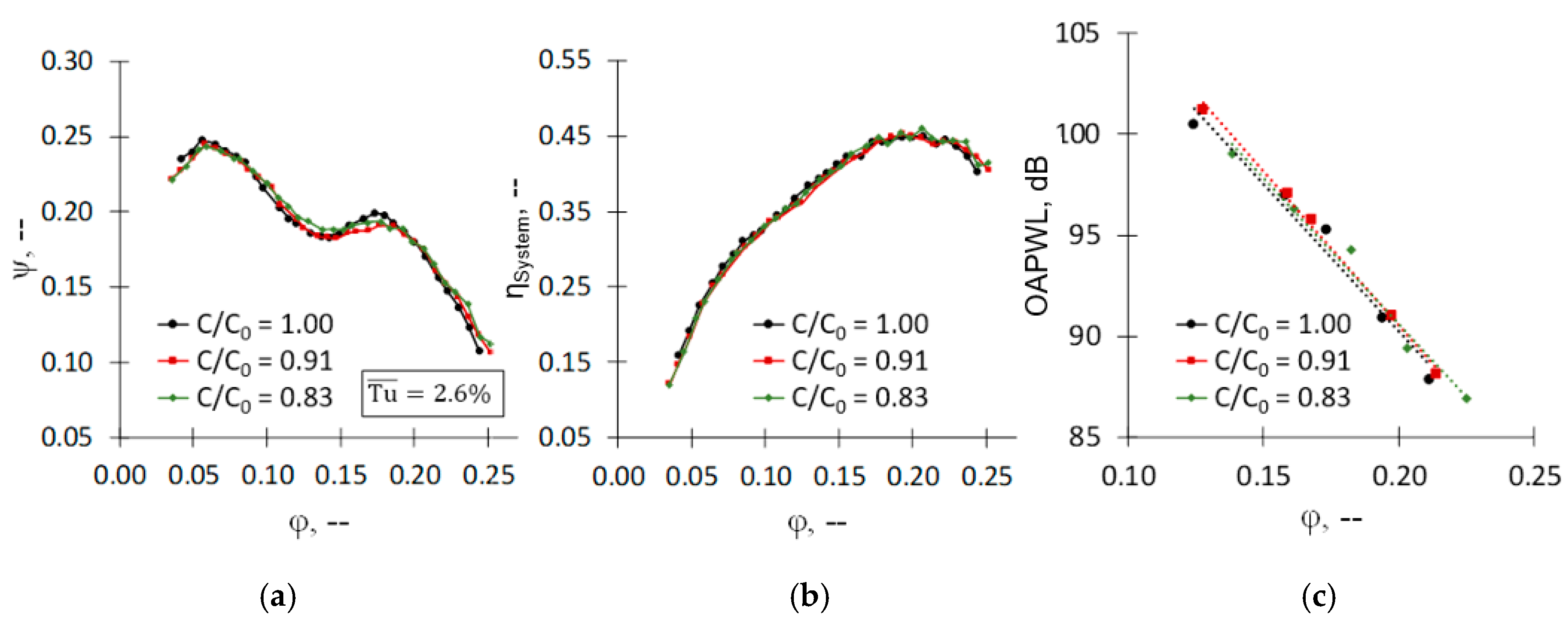
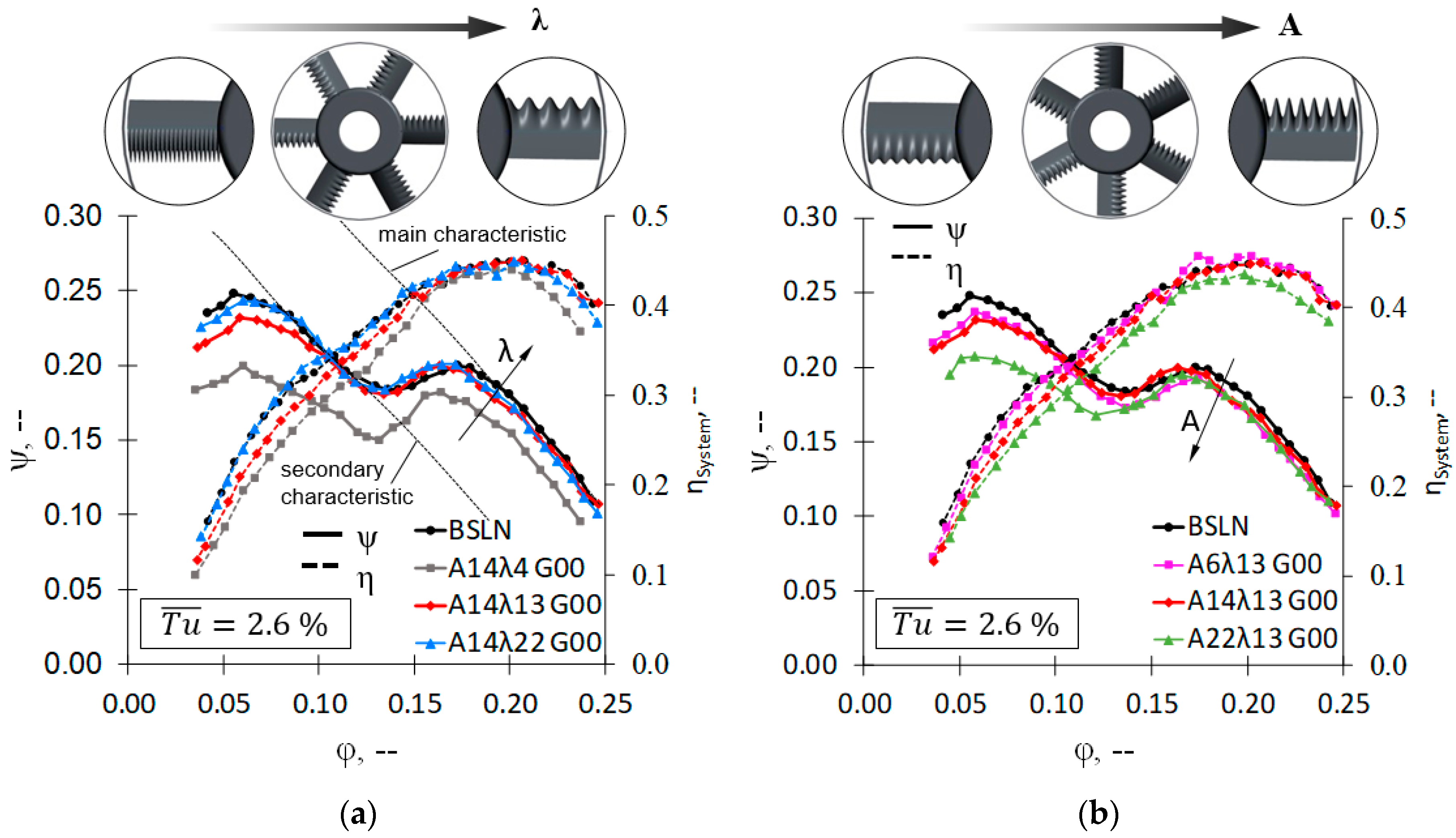
3.1. Low-Pressure Axial Fans: Aerodynamic Performance

Figure 8 shows the overall performance of the tested rotors in terms of aerodynamics at (a) varying serration wavelength and (b) serration amplitude. For brevity, the fan characteristic curves of the serration configurations tested as well as the baseline case are presented only at low turbulence intensity. Even though the full characteristic curves are analyzed, the fan design point can be stated to be at maximum efficiency, corresponding to φ = 0.20. In terms of aerodynamics, the results obtained are highly comparable to those of previously investigated single aerofoils [23], showing maximum performance for small serration amplitudes and high wavelengths. Serrations with low wavelengths and high amplitudes tend to show poorer performance, which can be attributed to the continuous increase in drag due to the vortex-generating and crossflow effects of the serrations.

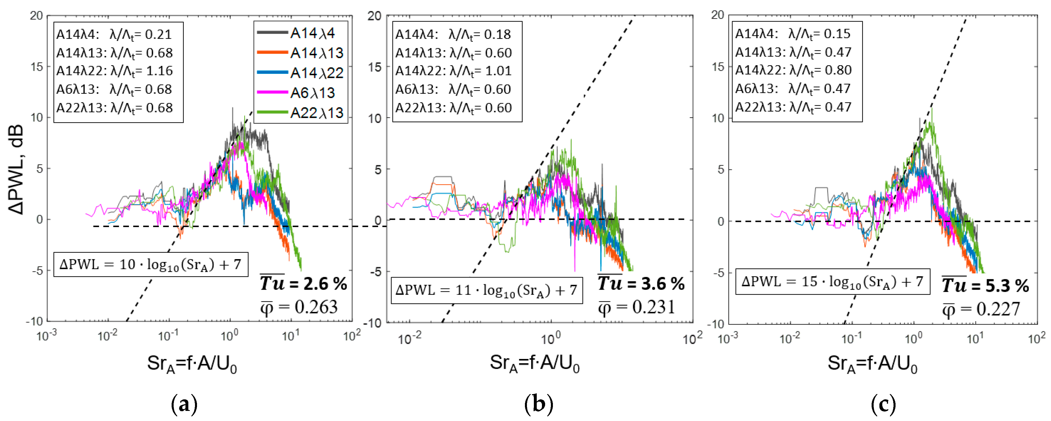
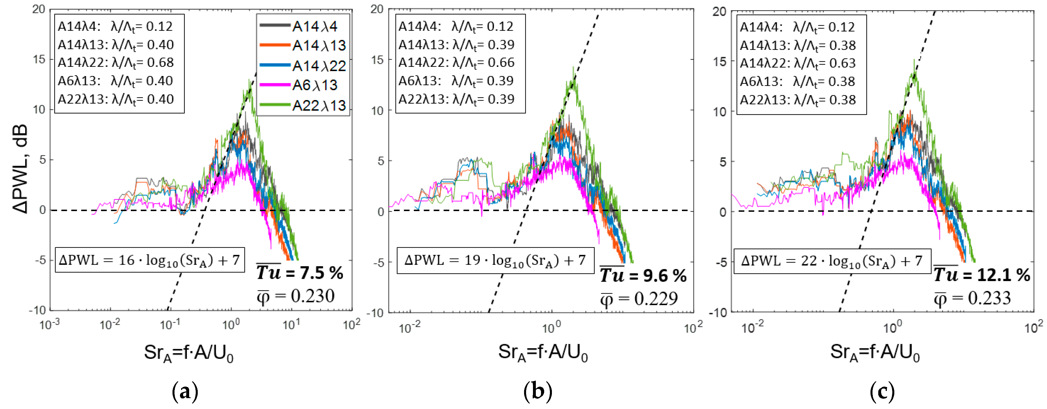
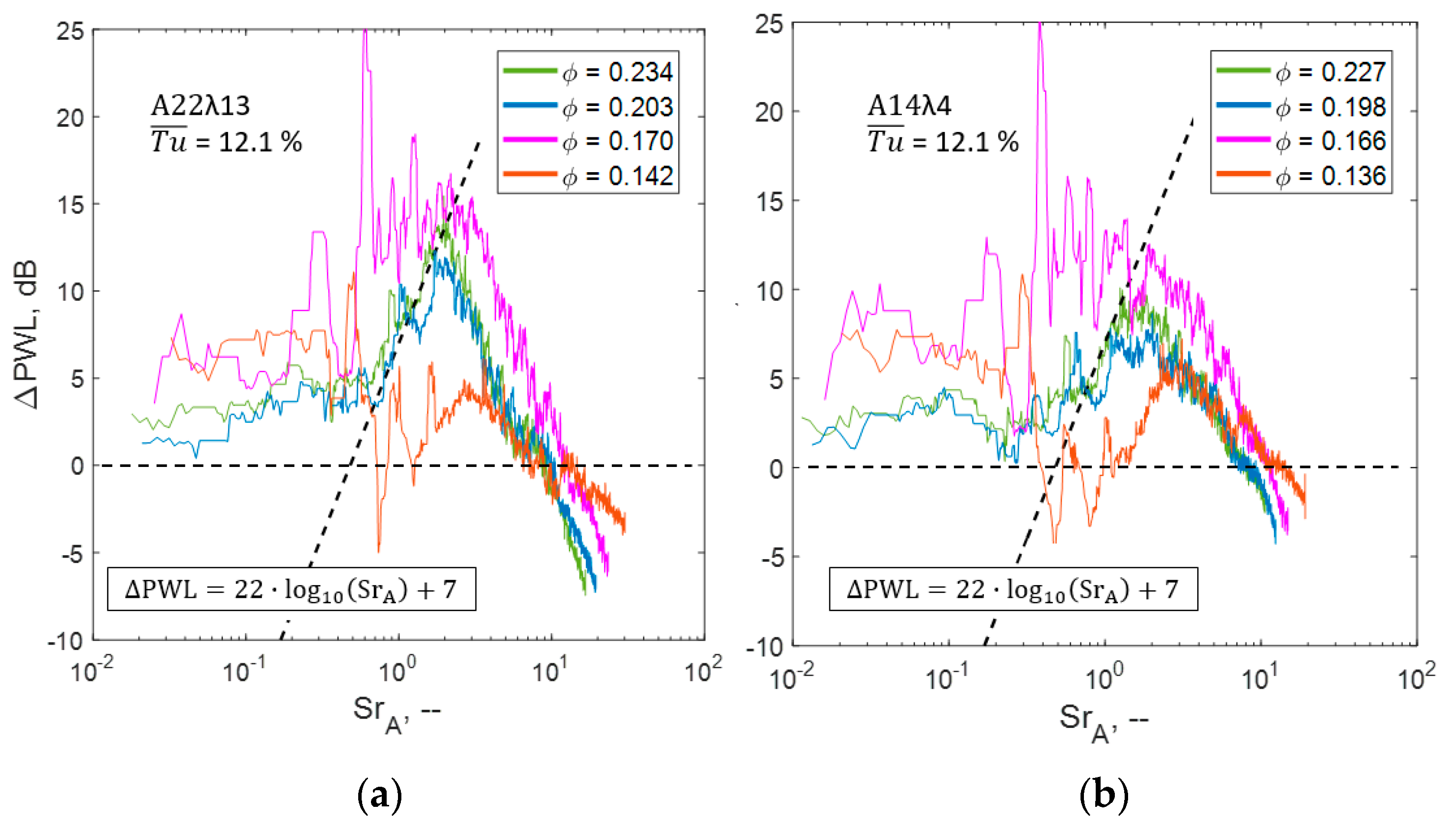
3.2. Low-Pressure Axial Fans: Spectral Broadband Noise Reduction

To compare the broadband noise reduction between single aerofoils and the rotating application, the gathered signals are filtered in the frequency domain according to Section 2 and only the resulting broadband spectra are further processed towards the spectral noise reduction as was done for Figure 2. Once again, the frequency is normalized via the Strouhal number (Equation (1)), based on the serration amplitude. To comply with the definition of the Tu, for the Strouhal number, the longitudinal velocity at the rotor plane U0 is chosen instead of taking the circumferential rotor mid-span velocity Urot.
Figure 9 and Figure 10 show the spectral noise reduction at varying turbulence intensities for the serrated rotors tested. According to the scaling of the spectral noise reduction discussed in Section 1, the results of the post-processed broadband signals are fitted via the least-squares minimization approach to the scaling laws by adapting the slope-determining prefactor as. This is followed by defining a common offset factor bs, controlling the parallel shift. Note that the bs is matched only at optimum design conditions of the serrations. The obtained trends reveal a quite similar logarithmic scaling as for single aerofoils, where maximum serration amplitudes and small serration wavelengths show the highest potential for reducing rotor-turbulence interaction noise. Modulating the incoming turbulence reveals the noise reduction capability to be scaling with the slope-determining prefactor as, which extends the currently known trends for isolated stationary aerofoils since, in direct comparison, turbulence of significantly higher levels is generated for the rotating application. The prefactors show to continuously increase from as = 10 for the lowest T u ¯ = 2.6% (Figure 9a) to as = 22 for the highest T u ¯ = 12.1% (Figure 10c), leading to local reductions of the sound power level of up to ΔPWL = 14 dB. In conclusion, the common spectral logarithmic scaling (Equation (1)) for both isolated aerofoils and full rotors, indicates a reduction of leading edge broadband noise following the well-known aeroacoustic noise reduction mechanisms of serrated leading edges (compare Section 1). At least for the broadband noise, this enables a direct transfer from stationary aerofoils to rotating applications for operation conditions close to the design point φ ≈ 0.18.
The obtained scaling laws for the broadband noise reduction hint at relatively high prefactors as when compared to the existing literature. However, the differences to previous studies can be attributed to the fact that, first, previous studies are focusing on rigidly mounted single aerofoils in turbulent streams. For these setups, it is not possible to generate conditions of homogeneous turbulence of Tu > 6% using passive turbulence generators as e.g., coarse grids. Consequently, the isolated stationary aerofoils are tested at moderately low turbulence intensities, which might be an argument for the lower prefactor as. In reverse conclusion, testing at similar Tu level for both isolated aerofoil and the full rotor is expected to lead to a comparable spectral scaling. Second, the high prefactors as for the rotating applications result from substantially higher Tu-Levels investigated, when compared to the isolated aerofoils. The initial spectral scaling law was defined by Chaitanya et al. [6] who did not investigate effects on the prefactor as since in their study the Tu and thus the integral length scales were not varied in wide margins. Varying the serration wavelength and the amplitude mainly showed effects on the parallel shift of the noise reduction, as it can be described by the constant bs. Accordingly, for the presented study a constant prefactor as can be defined for each turbulent case where the second constant bs is controlled by the optimum serration amplitude A and an optimum ratio of serration wavelength and integral length scale λ/ΛT.
At off-design conditions, however, the broadband leading edge noise not necessarily represents the dominant acoustic source. With reducing flow coefficients, rotor-specific acoustic effects such as separation noise and reverse flow effects from the tip-gap region as well as rotor speed-dependent tonal effects increase in relevance. Consequently, these effects also affect and attenuate the overall noise reduction potential of serrated rotors. This is evidenced in Figure 11, which shows the comparison of the spectral noise reduction capability at different on-design and off-design conditions at iso-speed of the rotor. At flow coefficients φ > 0.18, the grid-generated broadband noise is efficiently reduced, whereas at partial loading of the fan at φ ≈ 0.17 significantly stronger low-frequency components are induced and reduced.
Minimum flow coefficients again show a log-dependent scaling of the noise reduction, albeit at a considerably lower level. This void in the validity of the spectral scaling laws for flow coefficients φ ≤ 0.18 serves as a strong indicator that the mechanisms of the noise reduction differ from the hitherto known effects of leading edge serrations. More specifically, for the aerodynamic instability region of the fan characteristic curves, distinct aerodynamic effects such as a serration-induced delay in the onset of stall are considered being the key-effects in obtaining the significant overall noise reduction shown in Figure 12. The known aeroacoustic effects of decorrelation and interference are only of secondary importance for φ ≤ 0.18.

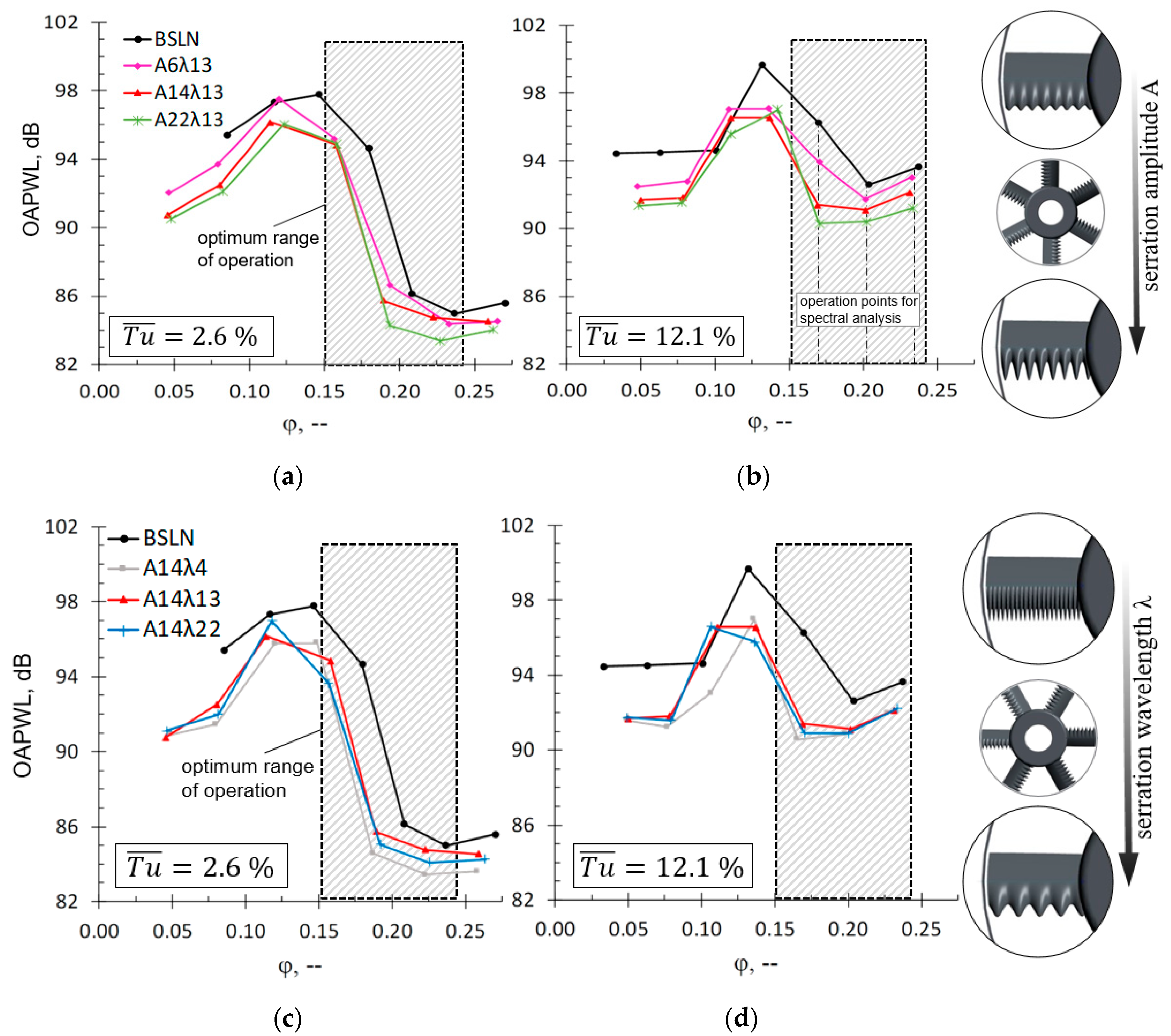
3.3. Low-Pressure Axial Fans: Overall Acoustic Performance

To assess the applicability of the spectral scaling laws for leading edge serrations requires a more general analysis of the aeroacoustic noise reduction pattern of the investigated low-pressure axial fans. In terms of acoustics, the overall effect of the tested rotors with and without leading edge serrations in Figure 12 shows that the baseline rotor radiates higher noise at all operation points. For maximum flow coefficients, the overall noise reduction is ΔOAPWL ≤ 2.5 dB. The most distinct differences to the baseline rotor, however, occur in the transition region from pre-stall (φ ≥ 0.18) towards instability (0.13 ≤ φ ≤ 0.18) leading to an increase of the noise reduction potential up to ΔOAPWL ≤ 6 dB for the high turbulent case (Figure 12b). Here, the serrations are supposed to shift the onset of the (aeroacoustic) stall towards smaller flow coefficients when compared to the baseline rotor. Given the fact that this shift is less distinct for the aerodynamic performance (Figure 8) leads to the hypothesis that small-scale separation at single blades is suppressed, not-yet affecting the overall pressure rise of the full fan.
The underlying effect is suspected to be an efficient reduction in small-scale separation due to the leading edge contour. This takes place via the vortex-generating character of the leading edge serrations [27,28], resulting in increased stability of the blades’ boundary layer as well as in an efficient shift of coherent structures in the blade tip region towards lower flow coefficients, as described in previous studies of the authors [16]. The known decorrelation and interference effects of the leading edge serrations [3] are still present though play a minor role in terms of the overall noise reduction. In consequence, for the instability region, the overall noise reduction results from a combination of aerodynamic and aeroacoustic effects of the leading edge serrations. The observed aeroacoustic shift tends to be more distinct at high turbulence, clearly scaling with the serration amplitude (Figure 12b). For the low turbulent case (Figure 12a,c), the shift benefits from the maximum noise reduction potential at maximum serration amplitudes, though generally showing a reduced extend. However, the resulting acoustic differences to the baseline case exceed those at high turbulence, resulting in an improved noise reduction potential (Figure 12b,d). This is meaningful insofar as the aeroacoustic onset of the stall is more distinct for the low turbulent case compared to the already high OAPWL at pre-stall and high incoming turbulence. The effect of the serration wavelength λ, illustrated in Figure 12c,d, is of reduced impact when compared to the serration amplitude. Small wavelengths lead to a slight attenuation of the radiated noise which is particularly true for the pre-stall region at high flow coefficients. Generally, the reduced effect of the serration wavelength is in close agreement with recent literature for isolated aerofoils [3,4,17].

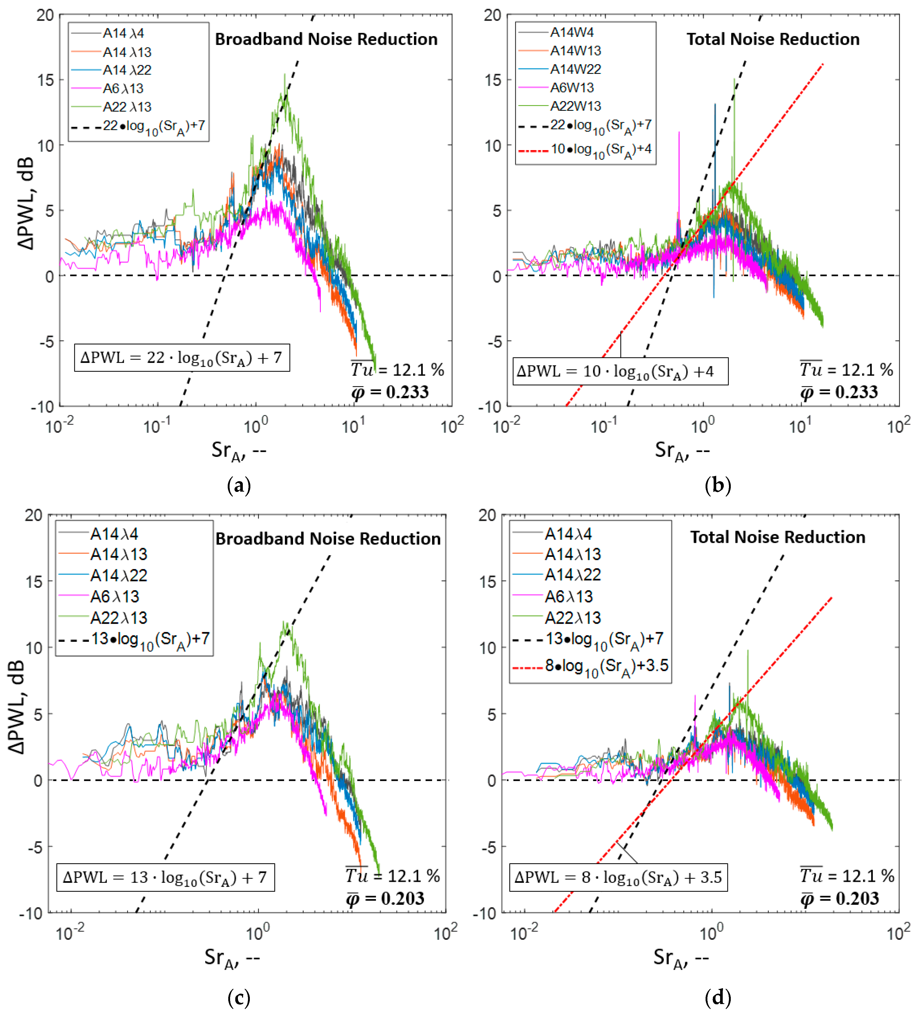
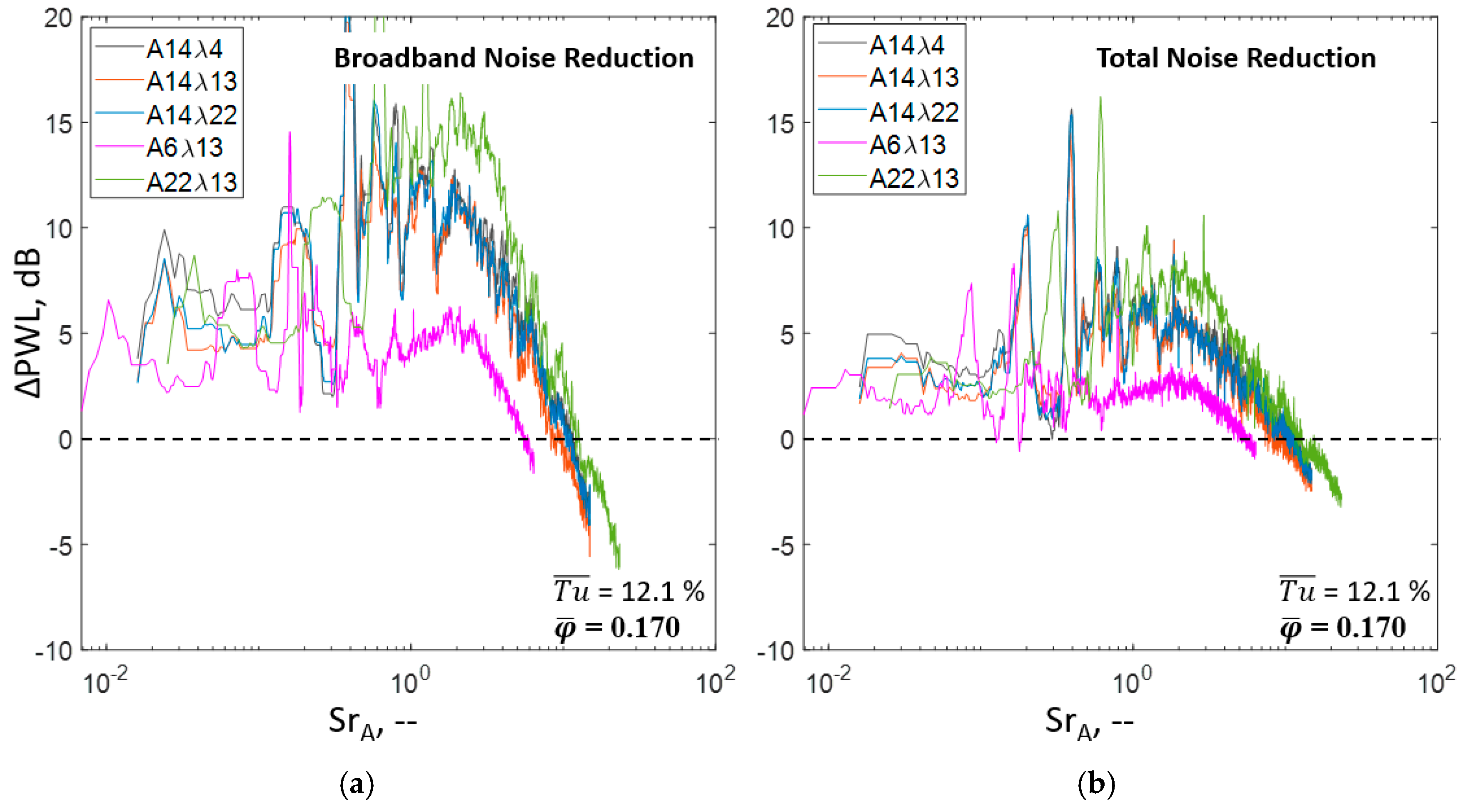
3.4. Low-Pressure Axial Fans: Broadband vs. Total Noise Reduction

Based on the overall sound power level in Figure 12, it is difficult and intricate to conclude on the broadband leading edge noise reduction potential of serrated rotors as well as the underlying physical mechanisms, in particular, once again highlighting the need to take into account the spectral composition of the noise reduction. In this context, the spectral composition of the noise reduction is extracted separately for the broadband components and the total noise signature. The results are presented in Figure 13 and Figure 14, showing the contrasting juxtaposition for three different operating points within the optimum range of operation (compare Figure 12). At flow coefficients φ ≥ 0.18, assigned to the pre stall region (Figure 13), where no relevant separation takes place, the spectral noise reduction for both broadband noise as well as total noise can be derived using the previously defined scaling functions. This hints at the dominance of the aeroacoustic working principles of leading edge serrations in this region. Analysis of the slope-determining prefactor as as well as the offset bs results in a clear devaluing when comparing broadband and total noise reduction. The reduction of low-frequency broadband noise (Figure 13a,c) is equalized by rotor noise of discrete character, resulting in only little total noise reduction for the low-frequency region (Figure 13b,d). Moreover, the presence of blade tip effects, scaling with the rotational speed further attenuate the noise reduction for the mid-frequency region. The resulting total noise reduction still is of significant order even though the initially defined reduction potential shows to be affected by additional rotor effects of both aerodynamic and acoustic nature. In terms of serration parameters, highly similar trends are observed for the broadband as well as the total noise reduction, enabling general statements of beneficial parameter combinations for maximum noise reduction.
Entering the instability region at φ = 0.17 (Figure 14) shows a deviating pattern, making the hitherto known scaling laws obsolete. A significant increase in low-frequency noise reduction is observed for the broadband noise but also being present for the total noise reduction. This supports the initial statement of predominantly aerodynamic effects being present for the increase of the acoustic stall margin. These effects in the form of a prevented flow separation mainly take place in the low-frequency range, resulting in high absolute noise reduction.

4. Conclusions

The conducted study provides detailed insights into the turbulence-induced broadband noise reduction capability of low-pressure axial fans equipped with leading edge serrations. A special focus of the conducted study is on the applicability of previously defined spectral scaling laws for the noise reduction of single aerofoils. In consequence, a coherent transfer analysis from single and rigidly mounted aerofoils towards a full axial fan was carried out by featuring identical aerofoil shapes, allowing to directly concluding on the transferability of the scaling laws from the rigid to the rotating domain. In terms of aeroacoustics, significant noise reduction is observed for various tested rotors with serrated leading edges where high amplitudes and, to a lesser degree, small wavelengths are found to be most beneficial. For the investigated rotors, a differentiation between the specific points of operation through the flow coefficients is inevitable. The classic broadband noise reduction due to spanwise decorrelation and destructive interference is observed for intermediate to high flow coefficients, corresponding to optimal and blade-congruent inflow conditions. For the instability region at partial load conditions, the dominant noise reduction mechanisms are proposed to be predominantly due to aerodynamic effects of the leading edge serrations, leading to a reduction of level-dominant low-to-mid-frequency noise. To assess the applicability of the spectral scaling laws concerning the overall noise reduction requires for an additional differentiation between the hitherto analyzed broadband noise reduction and the total noise reduction of leading edge serrations. For the pre stall region, the spectral scaling laws were found to describe, the relevant noise reduction to a reasonable level even though a devaluation of the broadband scaling laws is required to compensate for perturbations due to additional rotor-specific aeroacoustic effects. For the instability region of the fan, showing the maximum overall noise reduction, no such broadband scaling laws apply since aerodynamic serration effects, resulting in an onset of the aeroacoustic stall entry, cause the predominant noise reduction. Especially for fans operating close to the instability region, the interaction of aerodynamic and aeroacoustic effects of the serrations is considered highly important and is expected to assist in the future design of low-noise serrated rotors.

Author Contributions

Conceptualization, T.M.B., P.C. and N.H.; methodology, T.M.B.; software, T.M.B. and P.C.; validation, T.M.B. and N.H.; formal analysis, T.M.B., P.C. and N.H.; investigation, T.M.B., P.C. and N.H.; resources, T.M.B.; data curation, T.M.B., P.C. and N.H.; writing—original draft preparation, T.M.B.; writing—review and editing, T.M.B., P.C., N.H., F.K., C.O.P.; visualization, T.M.B., P.C., N.H.; supervision, F.K. and C.O.P.; project administration, T.M.B.; funding acquisition, T.M.B. All authors have read and agreed to the published version of the manuscript.

Funding

This research received no external funding.

Acknowledgments

The authors gratefully acknowledge the kind support of Daniel and David Delgado Hernandez in setting up the test rig and conducting the experiments.

Conflicts of Interest

The authors declare no conflict of interest.

References

  1. Devenport, W.J.; Staubs, J.K.; Glegg, S.A. Sound radiation from real airfoils in turbulence. J. Sound Vib. 2010, 329, 3470–3483. [Google Scholar] [CrossRef]
  2. Staubs, J.K. Real Airfoil Effects on Leading Edge Noise. Ph.D. Dissertation, Virginia State University, Blacksburg, WV, USA, 2008. [Google Scholar]
  3. Paruchuri, C.; Subramanian, N.; Joseph, P.; Vanderwel, C.; Kim, J.W.; Ganapathisubramani, B. Broadband noise reduction through leading edge serrations on realistic aerofoils. In Proceedings of the 21st AIAA/CEAS Aeroacoustics Conference, Dallas, TX, USA, 22–26 June 2015. [Google Scholar] [CrossRef]
  4. Chong, T.P.; Vathylakis, A.; McEwen, A.; Kemsley, F.; Muhammad, C.; Siddiqi, S. Aeroacoustic and Aerodynamic Performances of an Aerofoil Subjected to Sinusoidal Leading Edges. In Proceedings of the 21st AIAA/CEAS Aeroacoustics Conference, Dallas, TX, USA, 22–26 June 2015. [Google Scholar] [CrossRef] [Green Version]
  5. Narayanan, S.; Chaitanya, P.; Haeri, S.; Joseph, P.; Kim, J.W.; Polacsek, C. Airfoil noise reductions through leading edge serrations. Phys. Fluids 2015, 27, 25109. [Google Scholar] [CrossRef]
  6. Chaitanya, P.; Joseph, P.; Narayanan, S.; Vanderwel, C.; Turner, J.; Kim, J.W.; Ganapathisubramani, B. Performance and mechanism of sinusoidal leading edge serrations for the reduction of turbulence-aerofoil interaction noise. J. Fluid Mech. 2017, 818, 435–464. [Google Scholar] [CrossRef] [Green Version]
  7. Kim, J.W.; Haeri, S.; Joseph, P.F. On the reduction of aerofoil–turbulence interaction noise associated with wavy leading edges. J. Fluid Mech. 2016, 792, 526–552. [Google Scholar] [CrossRef] [Green Version]
  8. Turner, J.; Kim, J.W. Towards Understanding Aerofoils with Wavy Leading Edges Interacting with Vortical Disturbances. In Proceedings of the 22st AIAA/CEAS Aeroacoustics Conference, Lyon, France, 30 May–1 June 2016. [Google Scholar] [CrossRef]
  9. Turner, J.M.; Kim, J.W. Aeroacoustic source mechanisms of a wavy leading edge undergoing vortical disturbances. J. Fluid Mech. 2017, 811, 582–611. [Google Scholar] [CrossRef] [Green Version]
  10. Lau, A.S.; Haeri, S.; Kim, J.W. The effect of wavy leading edges on aerofoil–gust interaction noise. J. Sound Vib. 2013, 332, 6234–6253. [Google Scholar] [CrossRef] [Green Version]
  11. Lyu, B.; Azarpeyvand, M. On the noise prediction for serrated leading edges. J. Fluid Mech. 2017, 826, 205–234. [Google Scholar] [CrossRef] [Green Version]
  12. Chaitanya, P.; Joseph, P.; Narayanan, S.; Kim, J.W. Aerofoil broadband noise reductions through double-wavelength leading-edge serrations: A new control concept. J. Fluid Mech. 2018, 855, 131–151. [Google Scholar] [CrossRef] [Green Version]
  13. Corsini, A.; Delibra, G.; Rispoli, F.; Sheard, A.G. Aeroacoustic Assessment of Leading Edge Bumps in Industrial Fans. In Proceedings of the Fan 2015 Conference, Lyon, France, 15–17 April 2015. [Google Scholar]
  14. Arndt, R.E.; Nagel, R.T. Effect of leading edge serrations on noise radiation from a model rotor. In Proceedings of the AIAA 5th Fluid and Plasma Dynamics Conference, Boston, MA, USA, 26–28 June 1972. [Google Scholar] [CrossRef]
  15. Krömer, F.; Becker, S. Experimental investigation of the sound reduction by leading edge serrations on a flat-plate axial fan. In Proceedings of the 24th AIAA/CEAS Aeroacoustics Conference, Atlanta, GA, USA, 25–29 June 2018. [Google Scholar] [CrossRef]
  16. Biedermann, T.M.; Kameier, F.; Paschereit, C.O. Successive Aeroacoustic Transfer of Leading Edge Serrations from Single Airfoil to Low-Pressure Fan Application. ASME J. Eng. Gas Turbines Power 2019, 2019. [Google Scholar] [CrossRef]
  17. Biedermann, T.M.; Chong, T.P.; Kameier, F.; Paschereit, C.O. Statistical-Empirical Modelling of Airfoil Noise Subjected to Leading Edge Serrations. AIAA J. 2017, 55, 3128–3142. [Google Scholar] [CrossRef]
  18. Biedermann, T.M.; Czeckay, P.; Geyer, T.F.; Kameier, F.; Paschereit, C.O. Effect of Inflow Conditions on the Noise Reduction through Leading Edge Serrations. AIAA J. 2019, 57, 4104–4109. [Google Scholar] [CrossRef]
  19. Bampanis, G.; Roger, M.; Ragni, D.; Avallone, F.; Teruna, C. Airfoil-Turbulence Interaction Noise Source Identification and its Reduction by Means of Leading Edge Serrations. In Proceedings of the 25th AIAA/CEAS Aeroacoustics Conference, Delft, The Netherlands, 20–23 May 2019. [Google Scholar] [CrossRef]
  20. ISO. Acoustics—Determination of Sound Power Radiated into a Duct by Fans and Other Air-Moving Devices—In-Duct Method (ISO 5136:2003); International Organization for Standardization: Geneva, Switzerland, 2009. [Google Scholar]
  21. Carolus, T.H.; Starzmann, R. An Aerodynamic Design Methodology for Low Pressure Axial Fans with Integrated Airfoil Polar Prediction. In Proceedings of the 2011 ASME Turbo Expo, Vancouver, BC, Canada, 6–10 June 2011. [Google Scholar] [CrossRef]
  22. Biedermann, T.M.; Kameier, F.; Paschereit, C.O. Optimised Test Rig for Measurement of Aerodynamic and Aeroacoustic Performance of Leading Edge Serrations in Low-Speed Fan Application. In Proceedings of the 2018 ASME Turbo Expo, Oslo, Norway, 11–15 June 2018. [Google Scholar] [CrossRef] [Green Version]
  23. Biedermann, T.M. Aeroacoustic Transfer of Leading Edge Serrations from Single Aerofoils to Low-Pressure Fan Applications. Ph.D. Thesis, Technical University Berlin, Berlin, Germany, 2019. [Google Scholar] [CrossRef]
  24. Laws, E.M.; Livesey, J.L. Flow through Screens. Annu. Rev. Fluid Mech. 1978, 10, 247–266. [Google Scholar] [CrossRef]
  25. Nakano, T. A theory of homogeneous, isotropic turbulence of incompressible fluids. Ann. Phys. 1972, 73, 326–371. [Google Scholar] [CrossRef]
  26. Neise, W. Lärm und Lärmbekämpfung Bei Ventilatoren—Eine Bestandsaufnahme; DFVLR Forschungsbericht 80-16: Berlin, Germany, 1980. [Google Scholar]
  27. Hansen, K.L.; Rostamzadeh, N.; Kelso, R.M.; Dally, B.B. Evolution of the streamwise vortices generated between leading edge tubercles. J. Fluid Mech. 2016, 788, 730–766. [Google Scholar] [CrossRef]
  28. Chong, T.P.; Biedermann, T.; Koster, O.; Hasheminejad, S.M. On the Effect of Leading Edge Serrations on Aerofoil Noise Production. In Proceedings of the 24th AIAA/CEAS Aeroacoustics Conference, Atlanta, GA, USA, 25–29 June 2018. [Google Scholar] [CrossRef] [Green Version]
Figure 1. Juxtaposition of the sound pressure level SPL (Equation (6)) of a single NACA 65(12)-10 aerofoil vs. a 6-bladed axial fan, featuring the NACA 65(12)-10 as fan blades of span S [16]. Rotor blade chord C, serration amplitude A and wavelength λ downscaled by factor 2 at comparable blade incidence.
Acoustics 02 00030 g001
Figure 2. Spectral noise reduction (500 Hz ≤ f ≤ 5.8 kHz, 6th order median filtered) obtained from the 2D integration area. (a) Varying serration amplitude A; (b) Varying serration wavelength λ at Re = 350,000, AoA = 0 deg, aerofoil span S = 0.35 m, chord = 0.15 m. Figure adopted from [18].
Acoustics 02 00030 g002
Figure 3. (a) Aeroacoustic test rig according to ISO 5136 [23]; (b) Analyzed serration designs for the tested rotors. Absolute values for amplitude A and wavelength λ are indicated in mm. Rotor blade span S = 0.098 m, rotor blade chord C = 0.075 m, duct radius RDuct = 0.2 m.
Acoustics 02 00030 g003
Figure 4. (a) Local distribution of longitudinal velocity; (b) Circumferentially averaged turbulent properties vs. the radial duct position for the tested turbulence grids at n = 2000 min−1, T u ¯ = 12.1 % , and measurement plane = rotor plane.
Acoustics 02 00030 g004
Figure 5. Schematic of leading edge design including measures of importance. Both blades exhibit equal NACA 65(12)-10 properties. (a) Baseline case with a straight leading edge; (b) Serrated design, where grey hatching indicates reduced wetted area of the blade.
Acoustics 02 00030 g005
Figure 6. Validation of scaling approach by varying the chord length C of the baseline blades with C0 = 75 mm. (a) Non-dimensional static pressure rise ψ; (b) Aerodynamic efficiency η; (c) Overall sound power level OAPWL (Equation (7)).
Acoustics 02 00030 g006
Figure 7. (a) Example of a sound power level spectrum for the baseline rotor with applied filters, separating tonal and broadband effects; (b) Boundary conditions of customized filters [16].
Acoustics 02 00030 g007
Figure 8. Characteristic curves of pressure vs. flow coefficient for different rotor configurations. (a) Varying serration wavelength; (b) Varying serration amplitude.
Acoustics 02 00030 g008
Figure 9. Spectral sound power level reduction ΔPWL of the tested rotors at maximum flow coefficient φ and varying Tu. 20th-order median-filtered signals of broadband components only. Additional indication of the λ/Λt-ratio. (a) T u ¯ = 2.6%; (b) T u ¯ = 3.6%; (c) T u ¯ = 5.3%.
Acoustics 02 00030 g009
Figure 10. Spectral sound power level reduction ΔPWL of the tested rotors at maximum flow coefficient φ and varying Tu. 20th-order median-filtered signals of broadband components only. Additional indication of the λ/Λt-ratio. (a) T u ¯ = 7.5%; (b) T u ¯ = 9.6%; (c) T u ¯ = 12.1%.
Acoustics 02 00030 g010
Figure 11. Spectral sound power level reduction ΔPWL at varying flow coefficient for two rotor designs (a) A22λ13; (b) A14λ4.
Acoustics 02 00030 g011
Figure 12. OAPWL of rotor equipped with leading edge serrations of varying serration amplitude, serration wavelength λ, and incoming Tu. Grey hatching indicates the aerodynamic optimum range of operation. (a) Varying amplitude at T u ¯ = 2.6%; (b) Varying amplitude at T u ¯ = 12.1%; (c) Varying wavelength at T u ¯ = 2.6%; (d) Varying wavelength at T u ¯ = 12.1%.
Acoustics 02 00030 g012
Figure 13. Juxtaposition of spectral noise reduction ΔPWL for broadband and total noise while varying the serration parameters as well as the point of operation. (a) Broadband reduction at φ ¯ = 0.233%; (b) Total reduction at φ ¯ = 0.233%; (c) Broadband reduction at φ ¯ = 0.203%; (d) Total reduction at φ ¯ = 0.203%.
Acoustics 02 00030 g013
Figure 14. Juxtaposition of spectral noise reduction ΔPWL at partial load conditions φ ¯ = 0.17%. (a) Broadband reduction; (b) Total reduction.
Acoustics 02 00030 g014

