Abstract
When a hydrophone is deployed under the critical depth in deep ocean, the interference pattern will be complex and variable. The waveguide invariant is no longer constant and is treated as a distribution. The interference pattern is impacted by refracted and surface reflected (RSR) modes, as well as surface reflected and bottom reflected (SRBR) modes together. This phenomenon is illustrated by numerical simulation and explained by the waveguide invariant theory in this paper. The theory demonstrates: (1) The interference pattern in zone-b corresponds to the waveguide invariant that varies quickly and leads to the slope change, which is contributed by RSR modes whose phase velocity is less than the sound velocity at seafloor; (2) The interference pattern in zone-a1 and zone-c1 is corresponding to the that is the approximately 0.7 and leads to the stable slope, which is contributed by SRBR modes whose phase velocity is between the sound velocity at seafloor and sediment velocity; (3) The interference pattern in zone-a2 and zone-c2 is corresponding to the which hardly varies at low frequency but varies fiercely with source frequency increasing, so the striations are complex with high frequency, which is contributed by SRBR modes whose phase speed is between sediment speed and half space speed.
1. Introduction
The waveguide invariant (WI) theory has been introduced to quantify the slope of the interference striations in the range–frequency plane. It has been claimed that a scalar parameter is invariant to the details of the acoustic waveguide. When the sound speed is constant over the water column, the waveguide invariant is a scalar with a canonical value of 1.
In shallow water, the relation between the WI and interference striation has been investigated since the 1980s by many investigators. Chuprov [1] observed spectrograms from a broadband source with continuous spectral levels and first proposed the concept of the waveguide invariant. D’Spain et al. [2] derived an expression for the invariant to analyze the spectrograms in a shallow water environment where the bottom bathymetry varies with range and azimuth. Rouseff et al. [3] developed an algorithm for estimating WI distribution for a general measurement geometry, which is exercised for different shallow water waveguides. Le Gall et al. [4] transformed the acoustic intensity into the relative dispersion curve using a spatial Fourier transform and applied the Radon transform to estimate waveguide invariant distribution. Song et al. [5] adopted the concept of integral projection used in digital image processing and calculated the values for WI spectrum according to striation slope. Rouseff et al. [6] proposed a method to separate the positive WI components from the negative WI components and applied it to simulated data. Cockrell et al. [7] presented a method for calculating WI using a modal Wentzel-Kramers-Brillouin (WKB) approximation description of the acoustic field, which reveals a straightforward relationship between the sound speed profile and waveguide invariant. Zhao et al. [8] presented a clear explanation of how the value of WI is affected by the thermocline. However, the above works are all concentrating on the characteristic of WI in shallow water.
Considering deep water with a stratified sound speed profile, the distribution of WI is different from that in shallow water and the interference pattern is different as well, which will show unique characteristics. Li et al. [9] applied the waveguide invariant theory to the analysis of interference phenomena in the convergence zone and shadow zone. In the convergence zone, the acoustic intensity is mainly contributed by the refracted and refracted (RR) modes as well as the reflected and bottom refracted (RBR) with WI tending to positive infinity, leading to large slope of the intensity striations. In the shadow zone, the intensity interference striations contributed by the surface reflected and bottom reflected (SRBR) modes are almost the same as those in shallow water. Emmetiere et al. [10] developed the algorithm for estimating the WI distribution in deep water and analyzed the impact of source–hydrophone configuration on the WI distribution. However, the above works do not discuss the case that the hydrophone is deployed below the critical depth.
When the source is near the sea surface and a hydrophone is deployed below the critical depth, this propagation path can relieve the noise from distant sources to detect the target effectively [11,12]. Therefore, it is important to study the propagation features under this condition. The purpose of this paper is to analyze the interference pattern of the receiver below the critical depth and establish the corresponding relationship between interference pattern and WI.
This article divides normal modes into three parts: (1) refracted and surface reflected (RSR) modes with a phase velocity less than the sound velocity at the deepest depth in the water column; (2) SRBR modes with a phase velocity within the sound velocity at the deepest depth in the water column and sound velocity of the sediment, denoted as SRBR water-sediment (SRBRWS) modes; (3) SRBR modes with a phase velocity within the sound velocity of sediment and a sound velocity of half space, denoted as (SRBR sediment-half space) modes. We study the corresponding relationship between interference striations composed of three parts and waveguide invariants of three parts. This demonstrates that the application of waveguide invariant theory can interpret the interference pattern phenomenon of the receiver below the critical depth.
2. Waveguide Invariant Model
On the condition of ranges greater than several water depths, the underwater acoustic pressure field from a single omnidirectional point source can be expressed as a sum of normal modes. The source generates a tonal signal, with angular frequency, at a depth , and range . The omnidirectional point receiver is deployed at a depth . The complex pressure can be written as [13]:
where is the th-order horizontal wavenumber, and is the th-order mode amplitude as a function of depth. The source depth and receiver depth are constant, and the pressure is affected by both the source range and the broadband source frequency. Using a normal mode model to describe the acoustic pressure field in Equation (1), the interference acoustic intensity can be expressed as:
where
with being the difference between the th order mode horizontal wavenumber and the th mode order horizontal wavenumber, in which is not equal to . The source frequency spectrum is assumed as constant. The intensity is made up of two terms: the first one varies slowly with range and frequency, whereas the second one oscillates due to mode interference. Plotted versus range and frequency, the intensity fluctuation is dominated by the second term in the interference striation pattern. The first term approximately can be seen as constant and hardly impacts on it.
The intensity pattern often displays a rich structure due to the constructive and destructive interference. To identify contours of constant intensity interference striation, one can calculate directional derivative with respect to frequency and range, respectively:
In addition, the slope of the interference striation can be expressed as:
We assume that the first term in Equation (2) is approximately constant with range and frequency and is hardly influenced by range and frequency. The phase term is the main influence factor. According to Equation (2), we can obtain:
WI is defined as the slope of the interference striation in log–log space visible through a window from the range–frequency variability of the acoustic intensity [10]. It can be written as:
where is waveguide invariant, is phase slowness, the difference between the th mode and th mode. is the group slowness difference between the th mode and th mode. When acoustic intensity is made up of normal modes of which dispersive property are similar with each other, the and are not dependent on the number of modes. They can be placed outside the sum term. Equation (9) can be simplified to:
In the deep ocean, more than one group of normal modes with different dispersion are existing, when the source is located near the surface and the receiver is placed near the bottom where the sound velocity exceeds the maximum sound velocity in the vicinity of the surface. Three groups of normal modes that are different in nature may exist depending on their grazing angles. The higher order normal modes propagating through the critical depth and being reflected at both the surface and bottom boundaries are known as the SRBRWS modes and SRBRSH modes. The lower order normal modes being refracted upward before interacting with the sediment are named the RSR modes. The and are related to the number of modes, dispersive property is different with each other. will perform in different ways corresponding to the different dispersive normal modes, so the waveguide invariant for a particular pair of th mode and th mode is defined as:
where is phase velocity for the th mode and is group velocity for the th mode. Each describes the corresponding component of interference striations and it is different from others, so the interference pattern demonstrates the complex configuration in the range–frequency plane.
3. Numerical Simulation
We assume that the water depth is 5000 m. The waveguide used in the simulation is a typical deep-water environment as shown in Figure 1. The sound speed profile is a typical Munk curve and the deep sound channel has a typical depth of 1100 m. The sound speed at the ocean surface is 1548 m/s and that at the seafloor is 1567.3 m/s. The sediment is 50m thick and has a sound speed of 1600 m/s, density of 1600 kg/m3, and attenuation coefficient of 0.1 dB/λ. The sound speed of the lower half space is 1800 m/s, and density is 2200 kg/m3. The source depth is 150 m and the hydrophone is located at 4500 m in depth. Note that the critical depth is 4100 m. Frequency bandwidth is 50–350 Hz and source ranges are from 5 to 70 km.
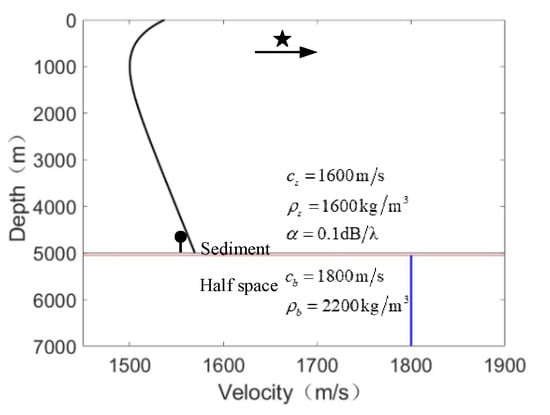
Figure 1.
Deep water environment with Munk sound speed profile.
The intensity in the range and frequency plane is shown in Figure 2. The horizontal axis which represents the range from the source to the hydrophone varies from 5 km to 70 km. The intensity does not exist in the range at less than 7 km. Intensity patterns in the range 7–20 km as well as 36–70 km, denoted as zone-a and zone-c, respectively, are similar to those observed in shallow water. However, the intensity pattern in the range 20–36 km is apparently different from the former, denoted as zone-b.
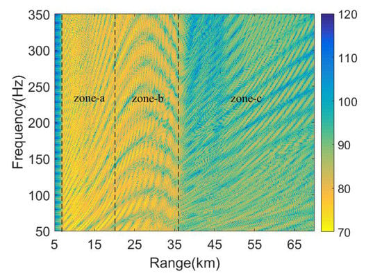
Figure 2.
Intensity versus range and frequency. The intensity is divided into three parts, such as zone-a, zone-b, and zone-c, according to artificial observation.
To explain this phenomenon, the intensity in the range–depth plane is shown in Figure 3. The source frequency is 200 Hz. The depth is 0–5000 m divided into 501 sections and the range is 0–70 km, divided into 7001 sections. The solid black line in the figure is the trajectory of source moving radially from the hydrophone. The hydrophone depth is 4500 m, and the range between source and hydrophone varies from 5 km to 70 km. One can find that zone-b in Figure 2 corresponds to the refracted zone which has no interaction with the sediment in Figure 3. In general, the acoustic field in the refracted zone is mainly contributed by the RSR modes corresponding to modes with the lowest turning points above the sediment. The acoustic field in zone-a and zone-c is interacted with the bottom, which are contributed by SRBR modes of which phase speeds are between the sound velocity at the deepest depth in the water column and half space velocity. Therefore, the interference patterns of intensity in Figure 2 may be determined by different groups of modes.
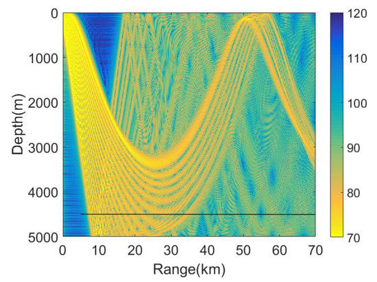
Figure 3.
Acoustic intensity from all modes. The solid black line is the trajectory of source moving radially from the hydrophone.
The transmission loss (TL) in Figure 3 is divided into two parts and shown in Figure 4. One includes the RSR modes only, which are shown in Figure 4a. The solid black line is located at the receiving depth between 20 km and 36 km. The range interval of the line corresponds to the range of zone-b, which is determined by RSR modes. Another includes the SRBR modes only, which are shown in Figure 4b. The range interval of the solid black line, which is influenced by SRBR modes, is 7–70 km. The zones-a, b and c are all influenced, and zone-b is especially contributed by both the RSR modes and SRBR modes.
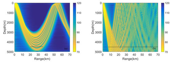
Figure 4.
Transmission loss. (a) Refracted and surface reflected (RSR) modes only, phase speeds are less than sound speed; (b) surface reflected and bottom reflected (SRBR) modes, phase speeds are between the sound velocity at the deepest depth in the water column and half space speed.
Now, we apply the waveguide invariant theory to analyze the interference phenomena in Figure 2. Using acoustic field calculation software KRAKEN codes [14], we can calculate the phase speed and the group speed. In terms of the theory in Section 2, the WI parameter, , can be calculated with the ratio between the difference of phase slowness and difference of group slowness. It is observed from Figure 5 that WI is distributed along the phase speed with different source frequencies.The dash lines are respectively corresponding to 1567.3 m/s and 1600 m/s. varies fiercely and irregularly with a phase speed less than the sound speed at the seafloor. When the phase speeds are between 1567.3 m/s and 1600 m/s, keeps stable and is not influenced by the frequency in general. In low-frequency cases, , of which phase speeds are more than the sediment speed 1600 m/s, can keep almost stable. However, as the source frequency increases, the change is increasingly more evident and fiercer.
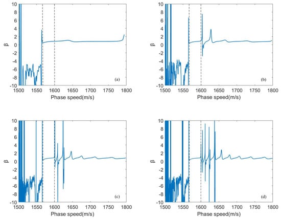
Figure 5.
The dependence of waveguide invariant (WI) on phase speed and frequency. (a) Frequency is 50 Hz; (b) frequency is 150 Hz; (c) frequency is 250 Hz; (d) frequency is 350 Hz.
To illustrate the relation between the waveguide invariant and the slope of interference striations, the intensity interference pattern is divided into several sections corresponding to the phase speed intervals in Figure 5, which is shown in Figure 6. As shown in Figure 6a, the slope of striations corresponds to , which varies evidently. The waveguide invariant is approximately 0.7, leading to the stable slope of striations and interference structure shown in Figure 6b. It can be observed that interference striation almost has the same slope. With the frequency increasing, the waveguide invariant changes fiercely. The striations tend to be more cluttered, shown in Figure 6c.
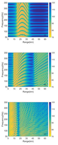
Figure 6.
Intensity according to phase speed intervals in Figure 5. (a) Phase speed < 1567.3 m/s; (b) 1567.3 m/s < phase speed < 1600 m/s; (c) 1600 m/s < phase speed < 1800 m/s.
Ultimately, we summarize the relationship between the waveguide invariant and the intensity interference. Intensity interference pattern is divided into five sections shown in Figure 7. According to the different groups of the normal modes, it can be observed that the region between 20 km and 36 km is mainly contributed by RSR modes, denoted as zone-b and the ranges of regions, 7–20km and 36–70 km, which are contributed by SRBR modes, which in turn are, respectively, denoted as zone-a and zone-c. SRBR modes are composed of two groups of modes, one of which the phase speeds range from the sound speed at the seafloor depth to the sediment speed and another of which the phase speeds are more than the sediment speed. The regions are contributed by SRBRWS modes, 15–20 km and 47–70 km, which are denoted as zone-a1 and zone-c1. The regions are contributed by SRBRSH modes, 7–15 km and 36–47 km, which are denoted as zone-a2 and zone-c2. Seen from Figure 7, the waveguide invariant contributed by RSR modes is changeable along the phase speed, leading to the variation of the slope of interference striations in the zone-b. The waveguide invariant is approximately 0.7, contributed by SRBRWS modes and leading to the stable slope of the interference striations in zone-a1 and zone-c1. The waveguide invariant, contributed by SRBRSH modes, becomes more changeable with frequency increasing, leading to the variation of interference striation in zone-a2 and zone-c2.
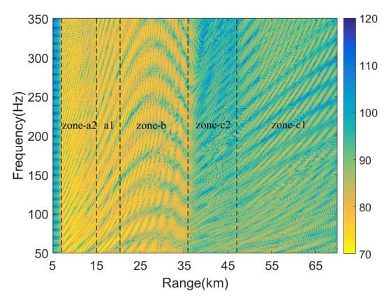
Figure 7.
Intensity versus range and frequency. According to Figure 6, it is divided into five sections: zone-a2, zone-a1, zone-b, zone-c2 and zone-c1.
We discuss how strongly the intensity and WI parameter depend on the variations of the attenuation coefficient. The intensity in the range–frequency plane is compared with different coefficients; see Figure 8. We can conclude that the attenuation coefficient apparently influences the intensity in zone-a2 and zone-c2, but intensity in zone-b is not influenced. The intensity in zone-a1 and zone-c1 is influenced a little by the variations of attenuation coefficient.
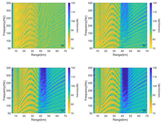
Figure 8.
The intensity varies with different attenuation coefficients. (a) 0 dB/; (b) 0.2 dB/; (c) 0.4 dB/; (d) 0.6 dB/.
We assume that the source frequency is 150 Hz and the WI parameter varies with different attenuation coefficients shown in Figure 9. The is hardly influenced by the attenuation coefficient and is approximately stable at 0.7. Therefore, the corresponding zone-a1 and zone-c1 striation has the same slope and does not vary with the attenuation coefficient.
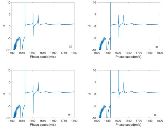
Figure 9.
The WI parameter varies with different attenuation coefficients. (a) 0 dB/; (b) 0.2 dB/; (c) 0.4 dB/; (d) 0.6 dB/.
4. Conclusions
The relationship between the interference pattern in the range–frequency plane and the WI for the hydrophone placed below the critical depth is analyzed. We calculate the corresponding waveguide invariants , and , and divide the interference pattern into several zones according to the different normal modes, such as RSR modes, SRBRWS modes and SRBRSH modes. Then, we point out that the interference pattern in zone-b corresponds to and the curved striations result from the changed . The interference pattern in zone-a2 and zone-c2 corresponds to , which hardly varies at low frequency but varies fiercely with source frequency increasing, so the striations are complex at high frequency. The interference pattern in zone-a1 and zone-c1 corresponds to which is stable at 0.7, so the striations almost have the same slope. The possible future research we may conduct is to estimate the source range and may perform an inversion of environmental parameters in zone-a1 and zone-c1 using the waveguide invariant theory.
Author Contributions
Conceptualization, Y.Y.; methodology, Y.Y. and X.L.; software, Y.Y.; writing—original draft preparation, Y.Y.; writing—review and editing, C.S. and X.L.; funding acquisition, C.S. All authors have read and agreed to the published version of the manuscript.
Funding
This research was funded by the National Natural Science Foundation of China (Grant No. 11974285, 11534009).
Acknowledgments
We appreciate all editors and reviewers for the valuable suggestions and constructive comments. Thank you to everyone who contributed to this article.
Conflicts of Interest
The authors declare no conflict of interest.
References
- Chuprov, S.D. Interference structure of a sound field in a layered ocean. In Ocean Acoustics, 3rd ed.; Brekhovskikh, L.M., Ed.; Springer: New York, NY, USA, 2003; Volume 6, pp. 128–148. [Google Scholar]
- D’Spain, G.L.; Kuperman, W.A. Application of waveguide invariants to analysis of spectrograms from shallow water environments that vary in range and azimuth. J. Acoust. Soc. Am. 1999, 106, 2454–2468. [Google Scholar] [CrossRef]
- Rouseff, D.; Spindel, R.C. Modeling the waveguide invariant as a distribution. Am. Inst. Phys. 2002, 621, 137–148. [Google Scholar]
- Gall, Y.L.; Bonnel, J. Passive estimation of the waveguide invariant per pair of modes. J. Acoust. Soc. Am. 2013, 134, EL230–EL236. [Google Scholar] [CrossRef]
- Song, W.H.; Wang, N.; Gao, D.Z. Concept of waveguide invariant spectrum and algorithm for its extraction. Acta Phys. Sin. 2017, 66, 114301. (In Chinese) [Google Scholar]
- Rouseff, D.; Zurk, L.M. On the sign of the waveguide invariant. In Proceedings of the IEEE OCEANS, Shanghai, China, 10–13 April 2016. [Google Scholar]
- Cockrell, K.L.; Schmidt, H. Modal Wentzel-Kramers-Brillouin approach to calculating the waveguide invariant for non-ideal waveguides. J. Acoust. Soc. Am. 2011, 130, 72–83. [Google Scholar] [CrossRef] [PubMed]
- Zhao, Z.D.; Wu, J.R.; Shang, E.C. How the thermocline affects the value of the waveguide invariant in a shallow water. J. Acoust. Soc. Am. 2015, 138, 223–231. [Google Scholar] [CrossRef]
- Li, Q.Q.; Li, Z.L.; Zhang, R.H. Application of waveguide invariant theory to the analysis of interference phenomena in deep water. Chin. Phys. Lett. 2011, 28, 034303. [Google Scholar] [CrossRef]
- Emmetiere, R.; Bonnel, J. Understanding deep-water striation patterns and predicting the waveguide invariant as a distribution depending on range and depth. J. Acoust. Soc. Am. 2018, 143, 3444–3454. [Google Scholar] [CrossRef] [PubMed]
- Duan, R.; Yang, K.D. A reliable acoustic path: Physical properties and a source localization method. Chin. Phys. B 2012, 21, 124301. [Google Scholar] [CrossRef]
- Li, Z.; Zurk, L.M.; Ma, B. Vertical arrival structure of shipping noise in deep water channels. In Proceedings of the IEEE OCEANS, Seattle, WA, USA, 20–23 September 2010. [Google Scholar]
- Jensen, F.B.; Kuperman, W.A. Computional Ocean Acoustics, 2nd ed.; Springer: New York, NY, USA, 2011; pp. 337–360. [Google Scholar]
- Porter, M.B. The KRAKEN Normal Mode Program; SACLANT Undersea Research Centre: La Spezia, Italy, 1991. [Google Scholar]
© 2020 by the authors. Licensee MDPI, Basel, Switzerland. This article is an open access article distributed under the terms and conditions of the Creative Commons Attribution (CC BY) license (http://creativecommons.org/licenses/by/4.0/).