Article

ACAT1 Benchmark of RANS-Informed Analytical Methods for Fan Broadband Noise Prediction—Part I—Influence of the RANS Simulation

by
Carolin Kissner
1,*,
Sébastien Guérin
1,
Pascal Seeler
1,
Mattias Billson
2,
Paruchuri Chaitanya
3,
Pedro Carrasco Laraña
4,
Hélène de Laborderie
5,
Benjamin François
6,
Katharina Lefarth
7,
Danny Lewis
8,
Gonzalo Montero Villar
9 and
Thomas Nodé-Langlois
10
1
Department of Engine Acoustics, Institute of Propulsion Technology, German Aerospace Center (DLR), 10623 Berlin, Germany
2
Aeroacoustics R & T Center, GKN Aerospace Engine Systems, SE-46181 Trollhättan, Sweden
3
Institute of Sound and Vibration Research (ISVR), University of Southampton, Southampton SO17 1BJ, UK
4
Aerodynamic Technology Department, ITP Aero, 28108 Alcobendas, Spain
5
Aerodynamics and Acoustics Department, Safran Aircraft Engines, 77550 Moissy Cramayel, France
6
Aeroelasticity, and Acoustics, Department of Aerodynamics, ONERA—The French Aerospace Lab, 92190 Meudon, France
7
Aeroelasticity, and Aeroacoustics, Department of Turbine Aerodynamics, MTU Aero Engines AG, 80995 Munich, Germany
8
CNRS, Laboratoire de Mécanique des Fluides et d’Acoustique, INSA Lyon, Université Claude Bernard Lyon I, Univ. Lyon, École Centrale de Lyon, 69134 Écully, France
9
Division of Fluid Dynamics, Department of Mechanics and Maritime Sciences, Chalmers University of Technology, SE-41296 Gothenburg, Sweden
10
Acoustics Methods, Airbus Commercial Aircraft, 31060 Toulouse, France
*
Author to whom correspondence should be addressed.
Acoustics 2020, 2(3), 539-578; https://doi.org/10.3390/acoustics2030029
Submission received: 19 June 2020 / Revised: 16 July 2020 / Accepted: 18 July 2020 / Published: 22 July 2020
(This article belongs to the Special Issue Aeroacoustics of Turbomachines)

Abstract

:
A benchmark of Reynolds-Averaged Navier-Stokes (RANS)-informed analytical methods, which are attractive for predicting fan broadband noise, was conducted within the framework of the European project TurboNoiseBB. This paper discusses the first part of the benchmark, which investigates the influence of the RANS inputs. Its companion paper focuses on the influence of the applied acoustic models on predicted fan broadband noise levels. While similar benchmarking activities were conducted in the past, this benchmark is unique due to its large and diverse data set involving members from more than ten institutions. In this work, the authors analyze RANS solutions performed at approach conditions for the ACAT1 fan. The RANS solutions were obtained using different CFD codes, mesh resolutions, and computational settings. The flow, turbulence, and resulting fan broadband noise predictions are analyzed to pinpoint critical influencing parameters related to the RANS inputs. Experimental data are used for comparison. It is shown that when turbomachinery experts perform RANS simulations using the same geometry and the same operating conditions, the most crucial choices in terms of predicted fan broadband noise are the type of turbulence model and applied turbulence model extensions. Chosen mesh resolutions, CFD solvers, and other computational settings are less critical.

1. Introduction

Reynolds-Averaged Navier-Stokes (RANS)-informed analytical methods are commonly used to predict noise emitted by fan stages. Once a RANS solution is available, analytical fan noise predictions require little additional effort in terms of computation resources and time. These methods are therefore highly attractive for the acoustic optimization of fan designs.
The predicted rotor-stator-interaction (RSI) broadband noise levels of RANS-informed analytical methods are not unique but rather depend on several factors:
  • the RANS input,
  • the preparation of the RANS input (i.e the extraction of flow and geometry, the reconstruction of wake flow and turbulence, the determination of integral turbulent length scales, etc.),
  • and the applied acoustic model.
The focus of this paper is a detailed investigation of the influence of the RANS simulation on the predicted fan broadband noise. The influence of the acoustic model is discussed by Guérin et al. [1] in a closely related paper. Both studies were performed for the short-gap configuration of the ACAT1 fan and the same technique was used for processing the RANS input data.
Guérin et al. [2] have recently performed an extensive study for this fan using an analytical RANS-informed approach. While experimental trends were well reproduced, the overall sound power levels were underestimated by up to 3 dB. These factors listed above can contribute to uncertainty related to the prediction of fan broadband noise with RANS-informed analytical method and can therefore lead to discrepancies compared to experimental data. However, it should be noted that analytical models rely on simplifying assumptions, which can also explain differences between predicted and measured noise levels.
In the past, first studies were presented to examine the influence of RANS inputs on fan broadband noise predictions. Grace et al. [3] and Maunus et al. [4] used an analytical broadband noise prediction approach developed by Ventres et al. [5] and Nallasamy and Envia [6] to investigate four different CFD solutions. The CFD solutions used roughly the same operating points but were performed with different CFD solvers, different two-equation turbulence models, and different mesh resolutions. One simulation considered only the fan and another simulation neglected the rotor tip clearance. Significant differences in background and wake turbulent intensity and wake width were observed. The sound power levels deviated by up to 5 dB at some frequencies. While this study clearly shows that the RANS simulation has an impact, the relatively small data set is not ideal for determining the most critical parameters related to a RANS simulation.
Another study was conducted by Jaron et al. [7,8]. The authors performed several RANS simulations using different turbulence models for the NASA Source Diagnostic Test (SDT) fan. It was found that analytically predicted fan broadband noise levels can deviate by up to 2 dB with respect to the turbulence model type. While this indicates that the choice of turbulence model is important, the study was limited to only four different models. In addition, the study was conducted using the same CFD code, the same mesh, and the same general settings. It can therefore not be determined whether other factors of the RANS simulation also influence the predicted broadband fan noise levels and whether the findings are valid for other RANS simulation setups as well.
In this paper, the authors analyze an extensive data set comprising more than 20 RANS simulations of the ACAT1 fan at approach condition. The RANS simulations were performed using different CFD solvers, different mesh resolutions, and different computational settings. To ensure a fair assessment regarding the impact on noise, all RANS simulations were processed using the same technique and the same analytical acoustic solver, that is, PropNoise [9]. The flow and turbulence characteristics in the interstage region and predicted sound power level spectra are compared to pinpoint the most important influencing parameters of RANS simulations. In addition, flow and turbulence characteristics are also compared to hot-wire measurements, while fan broadband noise levels are compared to acoustic measurement data. A better understanding and quantification of the impact of RANS influencing factors will help to better design and evaluate future analytical studies.

2. Methods

2.1. Experimental Setup and Used Measurement Data

A comprehensive measurement campaign was conducted at the UFFA test rig at AneCom AeroTest to study the ACAT1 fan configuration. A sketch of the entire test rig and an example of a typical RANS domain of the fan stage are shown in Figure 1. Note that the coordinate system is shown in terms of the averaged tip radius of the rotor ( r t i p = 0 . 428 m ). The hot-wire measurements were performed in the inlet duct at hot-wire position 0 (HW 0) and in the interstage section at hot-wire position 1 (HW 1) to quantify mean and fluctuating flow velocities. For a more detailed description of the hot-wire measurements, refer to the work of Meyer et al. [10]. In this paper, hot-wire data are used to evaluate the turbulence and flow characteristics of the RANS simulations in the interstage region. To determine the acoustics downstream of the fan stage, a linear microphone array (indicated as AX1 in Figure 1) was used to perform an axial wavenumber decomposition. The wavenumber decomposition enables the separation of acoustic and hydrodynamic pressure fluctuations [11]. Furthermore, a re-sampling of the signal allows for a synchronization with the rotor. The rotor-locked, that is, tonal components, can thus be effectively removed from the pressure fluctuations [12]. The sound power is then computed by assuming an equal energy density distribution between propagating modes of the same frequency bands [13]. The experimental data were first presented by Tapken et al. [14]. Further details regarding the acoustic measurements were also discussed by Behn et al. [15]. In this work, the experimentally determined sound power level data are used to evaluate the predicted fan broadband noise levels using different RANS inputs.

2.2. RANS-Informed Analytical Methods

RANS-informed analytical methods work as follows: A RANS simulation is performed for a fan stage. An example of a typical RANS domain for this case is shown in Figure 1. The RANS simulation is then processed to extract flow, turbulence, and geometry characteristics, which are needed as an input for the analytical acoustic method. The acoustic prediction relies on the acoustic analogy to provide sound power spectra up- and downstream of the fan stage. For this RANS benchmark, an additional post-processing of the acoustic results was necessary. As most of the RANS data were provided at an axial position upstream of the stator leading edges, a correction was introduced to consider the influence of the turbulence development between the analysis plane and the stator leading edges on the sound power levels.

2.2.1. RANS Simulations and Turbulence Modeling

The RANS simulation is critical for the predicted fan broadband noise spectra. A typical RANS simulation for turbomachinery applications uses a mixing-plane approach. For a mixing-plane approach, the rotor is simulated in the relative frame of reference, while the stator is simulated in the absolute frame of reference. The structure of the rotor wake is present in the rotating frame of reference and vanishes due to a circumferential averaging technique at the mixing-plane. In general, a RANS intended for fan broadband noise predictions features a high mesh resolution, particularly in the boundary layers and in the wake regions of the rotor blades. If a higher order spatial discretization scheme is chosen, the mesh can be coarser but the simulation is oftentimes less robust.
For RANS simulations, flow quantities are split into mean and fluctuating components. For compressible flows, the mean components include a density weighting, which is typically denoted as Favre averaging. Thus arises the closure problem: Due to the non-linearity of the convection term, terms of the so-called Reynolds stresses ρ u i u j ¯ appear in the momentum and energy equations. As a result, more unknown variables than equations exist, that is, the system of equations is undetermined. Further equations are therefore required to model the Reynolds stress tensor. The models that introduce these equations to determine the Reynolds stress tensor are known as turbulence models. They vary in complexity and range from simple algebraic models to differential Reynolds stress models. The choice of turbulence model was shown to have a significant impact on fan broadband noise [3,4,7,8]. Subsequently, an overview of turbulence models and turbulence model extensions that were applied during this benchmarking activity is given.

Linear Eddy Viscosity Turbulence Models

Linear eddy viscosity turbulence models are based on the the Boussinesq hypothesis [16]. The Boussinesq hypothesis proposes that the momentum transfer of turbulent eddies can be modeled analogously to the momentum transfer by molecular motion in Newtonian fluids. The local turbulent shear stresses of a flow depend linearly on the local mean rate of strain and the proportionality of this relation is denoted as an eddy viscosity. However, the hypothesis has some limitations [17,18]: Linear eddy viscosity models tend to fail for flows with streamline curvature, flows with system rotation, flows with turbulence-driven secondary flows, and flows with rapid changes in the mean strain rates. In stagnation points, the turbulent kinetic energy becomes unrealistically high if no additional constraints for non-equilibrium flows are introduced. In light of these shortcomings, some might argue that Boussinesq-based models are unsuitable for describing turbulence in complicated, three-dimensional flows. However, despite the fact that the validity of the Boussinesq hypothesis is violated for large portions of the flow field in a fan, Boussinesq-based turbulence models are widely used for fan applications. In fact, most simulations of this benchmark were performed using linear eddy viscosity models.
One popular turbulence model for turbomachinery applications is the Wilcox k- ω turbulence model [19]. It is a two-equation linear eddy viscosity model solving transport equations for the turbulent kinetic energy k and the specific turbulent dissipation rate ω . The model is particularly suited for computing the turbulence in near-wall flow fields but it is formulated for equilibrium flows, that is, the turbulence is self-preserving. Non-equilibrium flows are typically characterized by large pressure gradients like in stagnation points. Thus, a turbulence model extension is often used in combination with this turbulence model in order to overcome this issue.
The Shear-Stress-Transport (SST) k- ω turbulence model [20,21] combines the advantages of two turbulence models. The Wilcox k- ω turbulence model is used for near-wall flows and the k- ϵ turbulence model, for free stream flows. A blending function is used to transition between the two models. However, the blending function is empirically motivated and a known weak point of the model as it is prone to fail, particularly for complex flow fields and in the presence of high turbulence levels in free stream flows. Compared to the Wilcox k- ω model, the Menter SST model is formulated for non-equilibrium flows. If turbulence production is higher than dissipation, the eddy viscosity is limited so that the ratio of turbulent shear stress and turbulent kinetic energy remains constant. If turbulence production is not higher than dissipation, the standard k- ω formulation is applied. However, as turbulence production exceeds dissipation in flow regimes featuring adverse pressure gradients and separated flow, Menter’s model predicts larger flow separation bubbles than other commonly used models.
Another two-equation model is the Smith k-l turbulence model [22,23]. Instead of solving a time-scale based transport equation like the previous models, it uses a length-scale based formulation. The length scale l can be directly related to the specific turbulent dissipation rate ω :
ω k 1 2 C μ l ,
where C μ = 0 . 09 is a model constant. Note that the length scale l is not the same as an integral turbulent length scale. Whereas the Menter SST model uses a simple limiter to treat non-equilibrium flows, the k-l Smith model incorporates a more sophisticated, continuous non-equilibrium function. The model is suited for both near-wall and free-stream flows without relying on a blending function. Compared to the other two featured linear eddy viscosity model, its grid resolution requirements are less restrictive in the buffer zone and in the viscous sublayer.

Non-Linear Eddy Viscosity Turbulence Models

Non-linear eddy viscosity turbulence models were formulated to bridge the gap between the numerical robustness and simplicity of linear eddy viscosity turbulence models and the ability of differential Reynolds stress models (DRSM) to predict flows featuring anisotropic turbulence. These models are sometimes also referred to as explicit algebraic Reynolds stress models. The most common of this type of turbulence model is the Hellsten EARSM k- ω turbulence model [24]. It is essentially an extension of the Menter baseline k- ω turbulence model, which in contrast to the previously described Menter SST k- ω does not feature a limiter. The transport equations and the blending functions are identical to Menter’s baseline model but a non-linear term is added to Boussinesq’s turbulence stress definition to account for the Reynolds stress anisotropy in terms of the strain-rate and vorticity tensors. This additional, algebraic term was formulated using recalibrated data from a Launder, Reece, and Rodi DRSM [25].

Extensions of Eddy Viscosity Turbulence Models

Extensions are oftentimes applied when using eddy viscosity models. These extensions are typically intended to improve the physical accuracy of these models, for example, to overcome the limitations of the Boussinesq hypothesis or to better capture certain flow phenomena. However, these modifications can also be used to “tune” a RANS simulation to better match experimental data and the implementation of these extensions and calibration of coefficients can vary depending on the used RANS code. Specific extensions used during this benchmarking activity are subsequently introduced.
Stagnation point fixes are intended to curb the excessive production of turbulent kinetic energy in regions of the flow featuring large normal stresses, that is, in regions with strong acceleration as is the case near blade leading edges. These modifications are intended for turbulence models like the Wilcox k- ω , which is the only turbulence model used in this benchmark whose formulation is limited to equilibrium flows. One common model is the Kato-Launder modification, which can be used in combination with most two-equation turbulence models. It replaces one mean strain rate tensor S i j by the vorticity tensor Ω i j . The Reynolds stress tensor τ i j of the production term of the turbulence model in the transport equation for turbulent kinetic energy k is thus modified as follows:
τ i j = μ T | S | 2 μ T | S | | Ω | ,
where μ T denotes the eddy viscosity. Some codes use the modified production term for the entire flow field, while others introduce criteria—often based on vorticity and mean strain rate tensors—to switch between the two production term formulations. If the modification is applied for the entire flow field, the Kato-Launder modification essentially turns off turbulence production outside of boundary and shear layers, which can lead to problems for cases with a non-negligible level of background turbulence. In addition, Durbin [26] observed a spurious production of turbulent kinetic energy in swirling flows. Another stagnation fix is based on the Cauchy-Schwarz inequality u i u j ¯ 2 u i 2 ¯ · u j 2 ¯ and is sometimes referred to as Schwarz limiter. Using this inequality, a lower bound for the specific dissipation rate ω can be formulated:
ω = max ω , 3 2 2 S i j S i j .
Contrary to the Kato-Launder modification, the Schwarz limiter is always a local modification. It was observed that this limiter can cause an overestimation of the turbulent kinetic energy in the stagnation point. In a fan stage, the modification of the specific dissipation rate was found to lead to significantly lower turbulent length scales around the rotor blades as well as between the rotor wakes [8].
As turbulence models assume turbulent flow conditions in the entire flow fields, transition models can be added to include the transition from laminar to turbulent boundary layer flows. The γ - R e ϑ t transition model [27], a common correlation-based model, was used during this benchmark. This transition model introduces two further transport equations—one for the transition Reynolds number based on the momentum thickness R e ϑ t and one for the intermittency γ , which triggers transition. Advantages of this model are that it relies on local variables and can be adjusted based on experimental data.

Differential Reynolds Stress Turbulence Models

Due to the complex flow in turbomachines, the validity of the Boussinesq hypothesis is violated in large portions of the flow field. Differential Reynolds stress turbulence models (or second moment closure models) do not rely on the Boussinesq hypothesis and instead model the Reynolds stress tensor directly using six transport equations, whose formulations can be directly derived from the Navier-Stokes equations. Nonetheless, unclosed terms still remain, which need modeling. For these models, the production term is therefore formulated directly and even the most basic models can at least qualitatively capture the effects of swirling and curved flows and system rotation. However, it should be noted that differential Reynolds stress turbulence models can be less robust and require more computational effort than eddy viscosity turbulence models.
The Wilcox stress- ω turbulence model [18] is closely related to the Wilcox k- ω model. For computing the Reynolds stress tensor, Wilcox decided to use the simpler, linear pressure-strain correlation of Launder, Reece and Rodi (LRR) rather than the non-linear, more complex formulation of Speziale-Sarkar-Gatski (SSG) [28]. While this model solves the Reynolds stress tensor, the underlying transport equation for the specific turbulent dissipation rate remains the same and the turbulent kinetic energy transport equation can be recovered from the Reynolds stress equations. This also means that all closure coefficients are exactly the same for both models and that both models are particularly suitable for computing boundary layer flows. Wilcox [18] also states that both models therefore produce similar results.
The SSG/LRR- ω turbulence model [29] is formulated analogously to the Menter SST k- ω turbulence model. It blends two pressure-strain models: the LRR model—using the same formulation as the Wilcox stress- ω model—for boundary layer flows and the SSG model in free shear flows. The LRR model’s formulation is a simpler, linear model and therefore more robust than the SSG model, especially in near-wall flows. The SSG/LRR- ω model uses the same specific dissipation rate transport equation and the same blending function as both the Menter SST k- ω and Hellsten EARSM k- ω models.
The JH stress- ω h turbulence model [30,31,32] follows a different approach than the other two DRSM’s. Data of direct numerical simulations (DNS) were used to model the pressure-strain correlation. While the formulation of the pressure-strain is rather simple and linear, the coefficients are defined as functions of the turbulence anisotropy invariants as constant coefficients are not adequate for describing flows in areas close to walls. The formulation of the turbulent eddy viscosity was also optimized to match DNS data. Based on the transport equation for the two-point correlation, Jovanović et al. [33] showed that the dissipation tensor can be divided into a homogeneous part and contributions due to the inhomogeneity of the flow, which are equal to the viscous diffusion of the Reynolds stresses. Thus the scale-determining transport equation is formulated in terms of the specific homogeneous dissipation rate ω h . As the focus of formulating this model was to correctly describe the turbulence in boundary layer flows, the JH stress- ω h turbulence model was proven to be superior to the Menter SST k- ω , Hellsten EARSM k- ω , and SSG/LRR- ω models in predicting the flow features of streamline curvature, boundary layer, flow separation, and shock wave/boundary layer interaction [34].

2.2.2. Preparation of the RANS Input

In this paper and its companion paper [1], the same technique for processing the RANS data was applied. The RANS data were provided in the interstage region at the HW 1 position as shown in Figure 1. As the evaluation is typically performed along streamlines and streamlines cannot be extracted from a single axial position, it was assumed that the flow velocities are comparable for all simulations. As a consequence, streamlines were extracted from one RANS solution, for which the entire solution domain was provided, and the same streamlines were used for all RANS inputs. Note that only streamlines passing through the bypass duct between 1% and 97% relative to the OGV height were considered, that is, the contribution of the engine support stator to broadband RSI noise was neglected.
Only the turbulence characteristics were varied for the fan noise predictions. To ensure a fair comparison, it was necessary to apply the same post-processing technique for each data set on the evaluation plane at the HW 1 position. It should be noted that the subsequent post-processing not only serves to produce input for the acoustic solver but also to allow for a comparison of CFD and hot-wire data. The turbulent kinetic energy (TKE) k ¯ and turbulent integral length scale Λ ¯ were circumferentially averaged at each streamline position:
k ¯ = 1 2 π 0 2 π k ( ϑ ) d ϑ ,
and
Λ ¯ = 1 2 π 1 k ¯ 0 2 π k ( ϑ ) Λ ( ϑ ) d ϑ .
The integral turbulent length scale at each circumferential position Λ ( ϑ ) was determined in terms of the turbulent kinetic energy k ( ϑ ) and the specific dissipation rate ω ( ϑ ) :
Λ ( ϑ ) = C Re C μ k ( ϑ ) ω ( ϑ ) ,
where the C μ = 0 . 09 represents a constant, which is dependent on the formulation of the turbulence model, and C Re depends on the Reynolds number as described by Donzis et al. [35]. The definition of the turbulent length scale of Equation (6) is often referred to as a Pope-based [36] turbulent length scale. For high Reynolds numbers, C Re asymptotically approaches a value of 0.4. Therefore, C Re was set to 0.4 in this work (Values of 0.43 or 0.45 are also commonly used for C Re ). Note that the circumferential averaging of the turbulent length scale contains a weighting by the local turbulent kinetic energy. This technique was introduced by Jaron et al. [7] and has the advantage that it makes no assumption regarding the relative importance of background versus wake turbulence. This is particularly relevant for the presently studied case as the ingested turbulence level is not negligibly small (turbulent intensity of about 0.3%, turbulent length scale of about 0.04 m). The potential relevance of ingested turbulence is discussed in detail by Kissner and Guérin [37]. In addition, the method’s implementation is unambiguous.
Nonetheless, there are also alternative methods for computing integral turbulent length scales in interstage regions and the chosen technique can have a large impact on predicted fan broadband noise levels. To demonstrate this issue, the TKE-weighted, Pope-based method (see Equation (5)) used for this benchmark was compared to three alternative methods for one RANS data set:
  • a length scale determined by fitting the circumferential average of turbulence velocity frequency spectra Φ i i ( f ) ¯ = 1 2 π 0 2 π Φ i i ( f , ϑ ) d ϑ with a target spectrum [38],
  • a Pope-based length scale computed from circumferentially averaged turbulence characteristics Λ ¯ = C Re C μ k ¯ ω ¯ ,
  • and a Ganz-based, empirically motivated length scale Λ ¯ = 0 . 2 A d (where A represents the wake area and d the wake velocity deficit) [39].
A length scale determined by fitting a spectral average with a target spectrum, for example, with a von Kármán or Liepmann spectrum, is similar to introducing a TKE-weighting of length scales as long as homogeneous, isotropic turbulence can be assumed. In Figure 2, the resulting circumferentially averaged length scales and predicted fan broadband noise levels are therefore nearly identical. Both methods inherently differentiate between the contributions of wake and background turbulence and as the turbulence energy is contained in the wake, the length scale in the wake is dominant. Simply computing a length scale based on circumferentially averaged turbulence characteristics weighs contributions of wake and background turbulence equally and thus the averaged length scales are larger. These larger length scales between the wakes have a larger impact and dominate the smaller length scales of the wake region. This causes predicted broadband noise levels to increase at lower frequencies and the frequency peak to shift towards a lower frequency. Lastly, the Ganz-based approach is empirically motivated and relates the integral length scale directly to a wake width ( L w = A d ). This method is limited to two-dimensional flows. Near the tip wall, this restriction is violated and due to the complicated flow, the distinction between wake, boundary layer, and tip vortex is not possible. Therefore, the Ganz-based length scales increase rapidly close to the tip wall, whereas the values are close to the TKE-weighted and spectrally averaged turbulent length scales in regions, where the flow behaves similarly to a two-dimensional flow. Yet the impact of that increase in length scale near the tip region has a significant impact on the predicted noise levels, as the levels increase at low frequencies and the peak frequency is shifted to a lower frequency. A similar effect was observed by Lewis et al. [40], who compared Jurdic-based to Pope-based length scales. The length scale definition of Jurdic ( Λ ¯ = 0 . 21 L w ) is closely related to Ganz, except that the wake width definition differs and the coefficient is equal to 0.21 instead of 0.2. Note that the Strouhal number in Figure 2 was defined as S t = f · r t i p u 0 , where r 0 is the averaged rotor tip radius ( r 0 = 0 . 428 m ) and u 0 is the averaged total velocity at the HW 1 position for one representative RANS simulation ( u 0 = 128 m / s ). These two variables will subsequently be used throughout the paper to compute all non-dimensional parameters.

2.2.3. Analytical Acoustic Model

The prediction of fan broadband noise was performed using PropNoise [9]. It was assumed that broadband RSI noise is the dominant broadband noise source of the fan stage, for example, compared to Engine Support Stator noise or to rotor and stator self-noise. The analytical model relies on the acoustic analogy and an in-duct Green’s function was applied. The source term for fan broadband noise is a function of the von Kármán transverse velocity frequency spectrum, which is computed using the circumferentially averaged turbulent kinetic energy and turbulent length scale values extracted from the RANS simulations at each considered streamline position. Rotor shielding and cascade effects are neglected. Further details regarding the models of PropNoise are given by Moreau [9] and by Guérin et al. [1,2].

2.2.4. Post-Processing of Acoustic Results

The turbulence characteristics of each RANS simulation were extracted at the axial position of the HW 1 probe in the fan interstage, while the turbulence characteristics at the stator leading edge positions are critical for noise generation. In order to achieve an optimal comparison to experimental data, a correction was introduced to account for the fact that the turbulence changes between the evaluation plane and the stator leading edge.
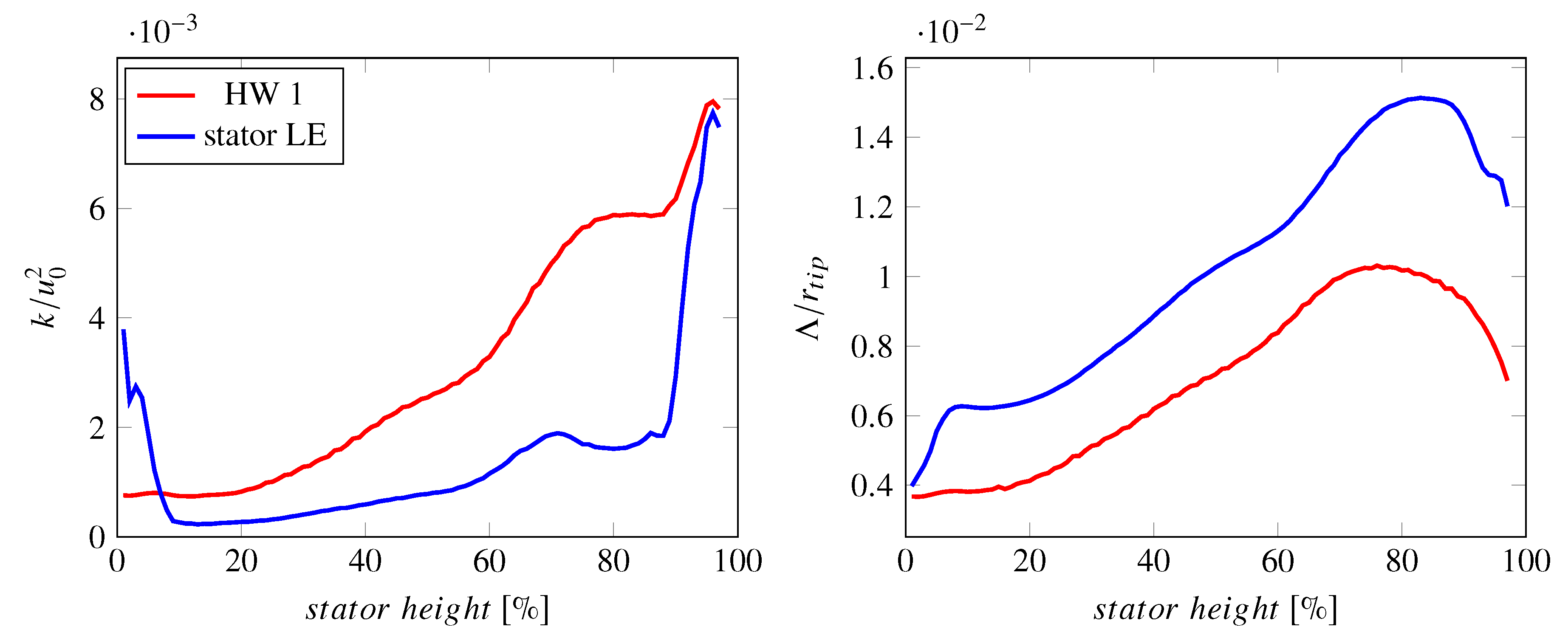
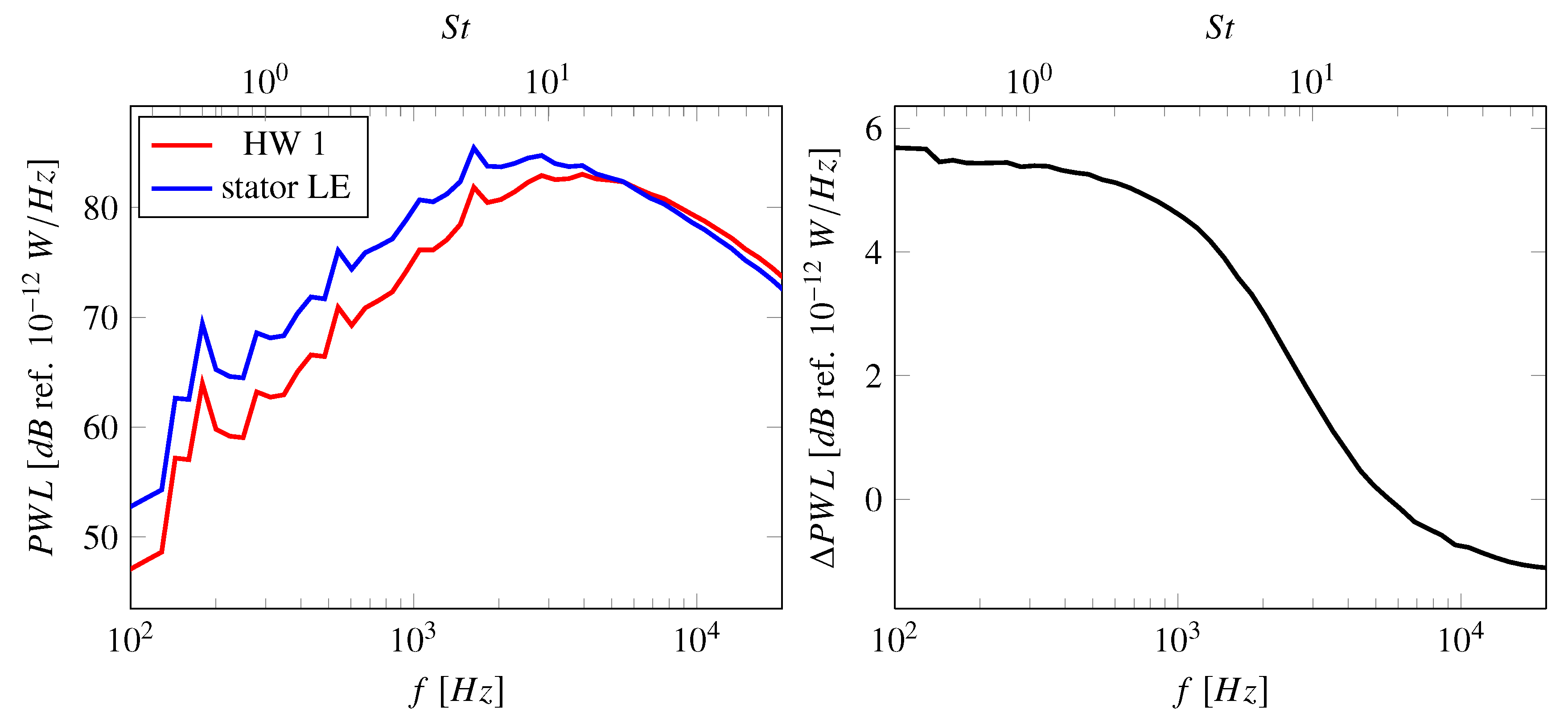
For one of the RANS simulations, wake characteristics at different streamline positions between the mixing-plane and the leading edge were reconstructed using semi-analytical models introduced by Jaron [8]. This procedure could not be applied to most RANS simulations as this extrapolation method requires data at several axial positions between the rotor trailing edge and the mixing plane, particularly in the interstage, and data from most RANS simulations were only available at one axial position. The relative change in turbulence characteristics between the HW 1 position and the stator trailing edge was therefore computed for one RANS simulation and analogously applied to all RANS simulations. Of course, this assumes that the turbulence develops similarly between the HW 1 and stator LE positions for all RANS simulations. The difference in turbulence characteristics extracted at HW 1 position and reconstructed at the stator leading edge is shown in Figure 3. The turbulent kinetic energy is lower at the stator LE than at the HW 1 position, while the turbulent length scale increases. The change in turbulence characteristics has an effect on the predicted fan broadband noise spectrum as it shifts the spectral peak to lower frequencies and slightly increases the amplitude. The difference in spectra is plotted on the right in Figure 4 and this difference is added to all spectra, which were computed based on turbulence characteristics at the HW 1 position.

2.3. Overview of Used RANS Simulations

Over 20 simulations were analyzed for this benchmarking activity. Different CFD solvers and turbulence models were used. While all RANS simulations were performed at approach conditions, there are some smaller differences in fan rotational speed, mass flows, ingested turbulence characteristics, and ambient conditions. Mesh sizes ranged from 4.5 to 70 million cells and slightly different tip clearance values were used. In the following section, these differing settings are shown in more detail. The impact of these RANS settings on the mean and turbulence characteristics and on the final acoustic predictions is discussed in Section 3.

2.3.1. Solvers and Turbulence Models

Many different commercial and research CFD codes are included in the data set. Used turbulence models range from linear eddy viscosity to differential Reynolds stress turbulence models (see Table 1). Some partners have also applied the previously mentioned turbulence model modifications to offset some of the shortcomings associated with the Boussinesq assumption (RANS 11 and 12), to optimize performance for non-equilibrium flow (RANS 9, 11, 13–16), or to include transition phenomena in boundary layer flows (RANS 14).

2.3.2. Operating Conditions

Small differences in operating conditions can be seen in Table 2. During the experimental campaign, each operating point was measured three times: for performance, hot-wire, and acoustic measurements. The operating points at approach were slightly different during these measurements as documented by Guérin et al. [2]. Most RANS simulations (RANS 1–8, 10, 12, 15–21) were performed using the approach operating point during performance measurements. Some simulations (RANS 9, 13, 14) used the corrected approach operating conditions, which were normed to ISA atmospheric conditions, during performance measurements. One simulation (RANS 11) applied the approach operating conditions during acoustic measurements. The offset in sound power level due to these small differences is expected to be negligible. The choice of inlet turbulence varies more significantly. Prior to the testing campaign, ingested turbulence was predicted to have a turbulent intensity of 1% and turbulent length scale of 0.01 m. To quantify the actual inlet turbulence during the testing, a filtering method was applied to suppress tones and signal contaminations. The turbulence spectrum measured by the hot-wire in the inlet was then fitted to a von Kármán or Liepmann spectrum in order to determine turbulent intensities and turbulent length scales. It should be noted that this is only permissible for homogeneous, isotropic turbulence, that is, not in the boundary layer. The fitting technique should also not be applied to frequencies above 8 kHz because the measured turbulence levels decrease rapidly at high frequencies due the wire thickness. Two groups of researcher used such fitting techniques and determined turbulent intensities of 0.3% and 0.23% and turbulent length scales of 0.04 m or 0.01 m were found. The small differences in values can be attributed to different factors—different fitting algorithms, different analysis positions, or different techniques for removing contamination from the measured signals. However, prescribing these inlet turbulence values for RANS simulations can be tricky for multiple reasons—(1) Few turbulence models and solvers are equipped for handling such large turbulent length scales in an otherwise free-stream domain. (2) If the inlet length is large, most of the prescribed turbulence decays before it interacts with the fan stage because in an ideal simulation, there is no turbulence production in a fan inlet. If broadband RSI noise resulting from the interaction of wake turbulence with the stator leading edges is indeed dominant (which seems to be the case for the investigated case), the differences in ingested turbulence characteristics are negligible.

2.3.3. Geometry and Meshing

For fan broadband noise predictions using a RANS-informed analytical approach, one key aspect of the mesh design is to ensure a good resolution of boundary layers and wake regions of the rotor blades. Mesh sizes range from 4.5 to 70 million cells and the azimuthal wake resolution at approximately 75% of the stator height ranges from 15 to 30 cells (see Table 3). Some of the simulation setups featuring a large number of cells were designed to initialize scale-resolving simulations or to accommodate the computation and propagation of fan tones. All RANS meshes feature fully resolved boundary layers on the rotor blade surfaces. The spatial discretization scheme is relevant for the meshing process as a higher order scheme allows for a coarser mesh resolution but also tends to be less robust. Most RANS simulations used 2nd order schemes, which are standardly applied. The CFX high resolution scheme switches between 1st and 2nd order accuracy depending on the local flow field to ensure the simulation’s robustness. Structured, unstructured, and hybrid mesh topologies are included in the data set. The tip clearances are slightly different. The values measured during testing were 0.58 mm at the rotor leading edge (LE) and 0.67 at the rotor trailing edge (TE), while the predicted value was 0.78 mm. For some simulations, the test values (or their average) were used. The other simulations were performed using the predicted value as the offset between predicted and measured values are within the uncertainty of the tip clearance sensors.

3. Results and Discussion

In this section, the influence of RANS parameters such as choice of CFD solver, mesh resolution, and turbulence model settings are discussed in terms of flow and turbulence characteristics at the HW 1 position as well as predicted fan broadband noise levels. The results will be compared to measured flow and turbulence characteristics and to sound power levels downstream of the stator vanes.

3.1. Influence of the Menter SST k- ω Turbulence Model

RANS simulations 1–8 were performed using the Menter SST k- ω turbulence model without applying any additional stagnation point fixes, rotational effects fixes, or transition models. Nearly the same operating points were used. Only the ingested turbulence varied. The simulations were performed using different solvers and drastically different mesh resolutions.
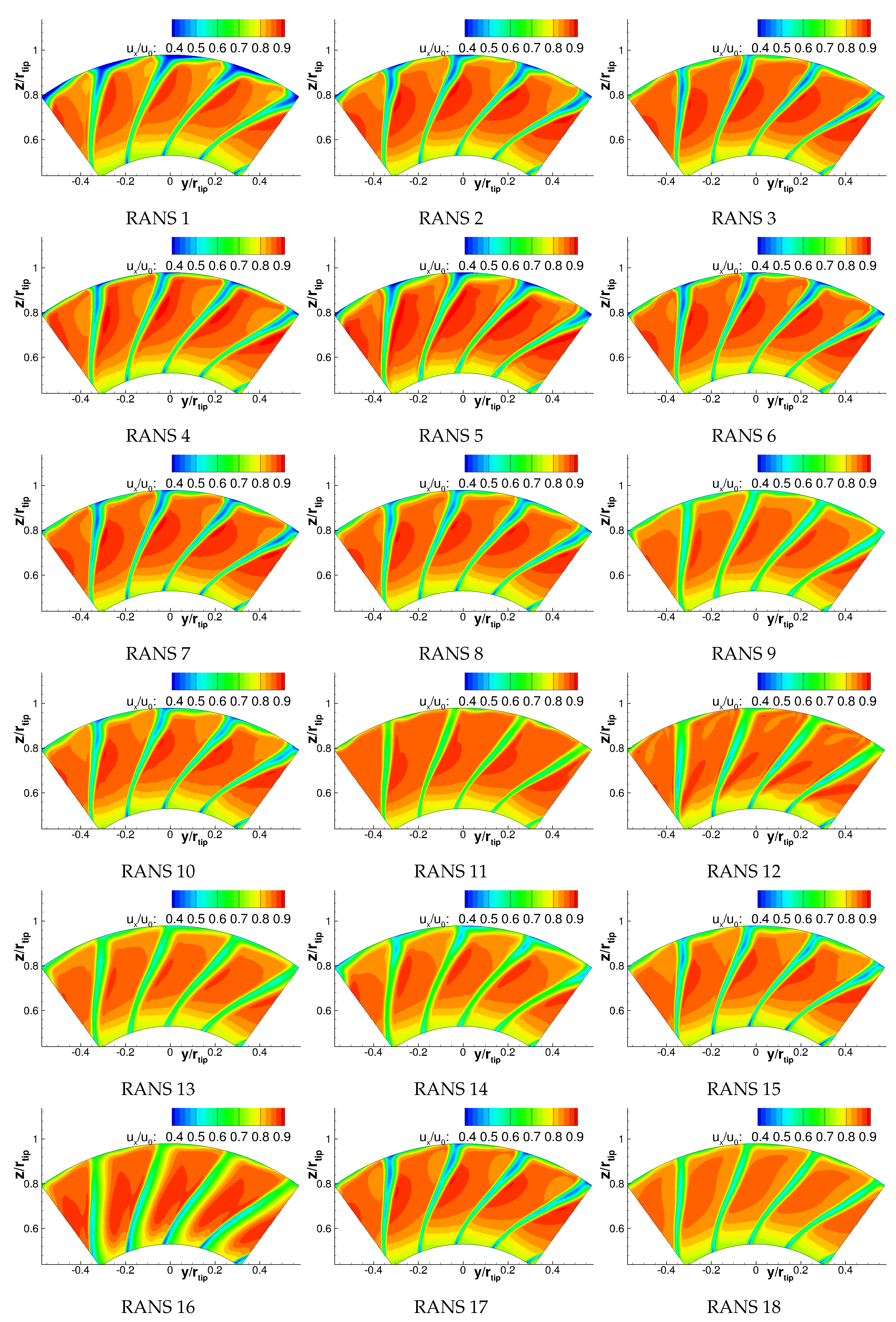
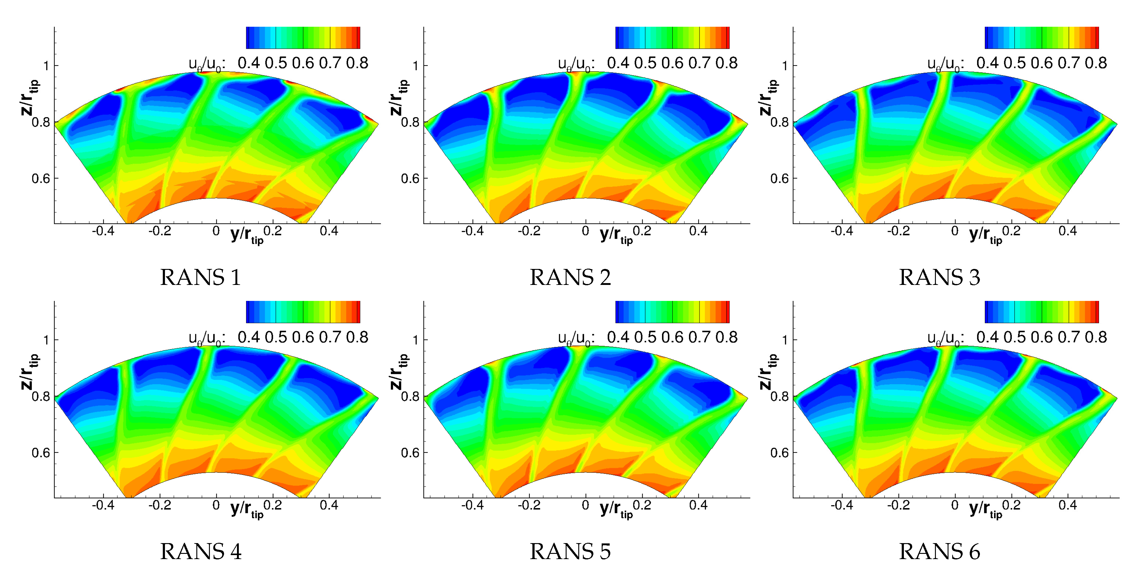
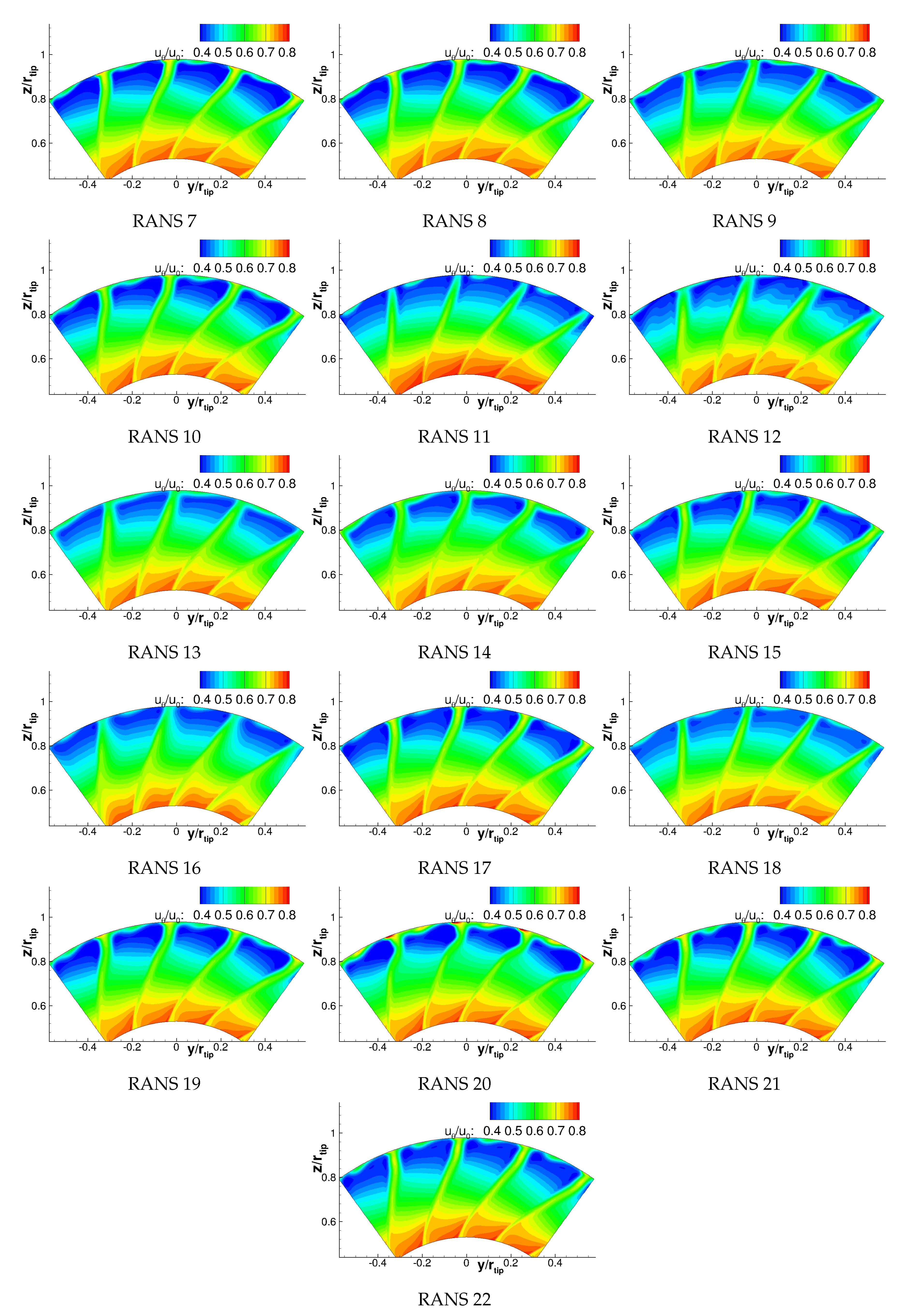
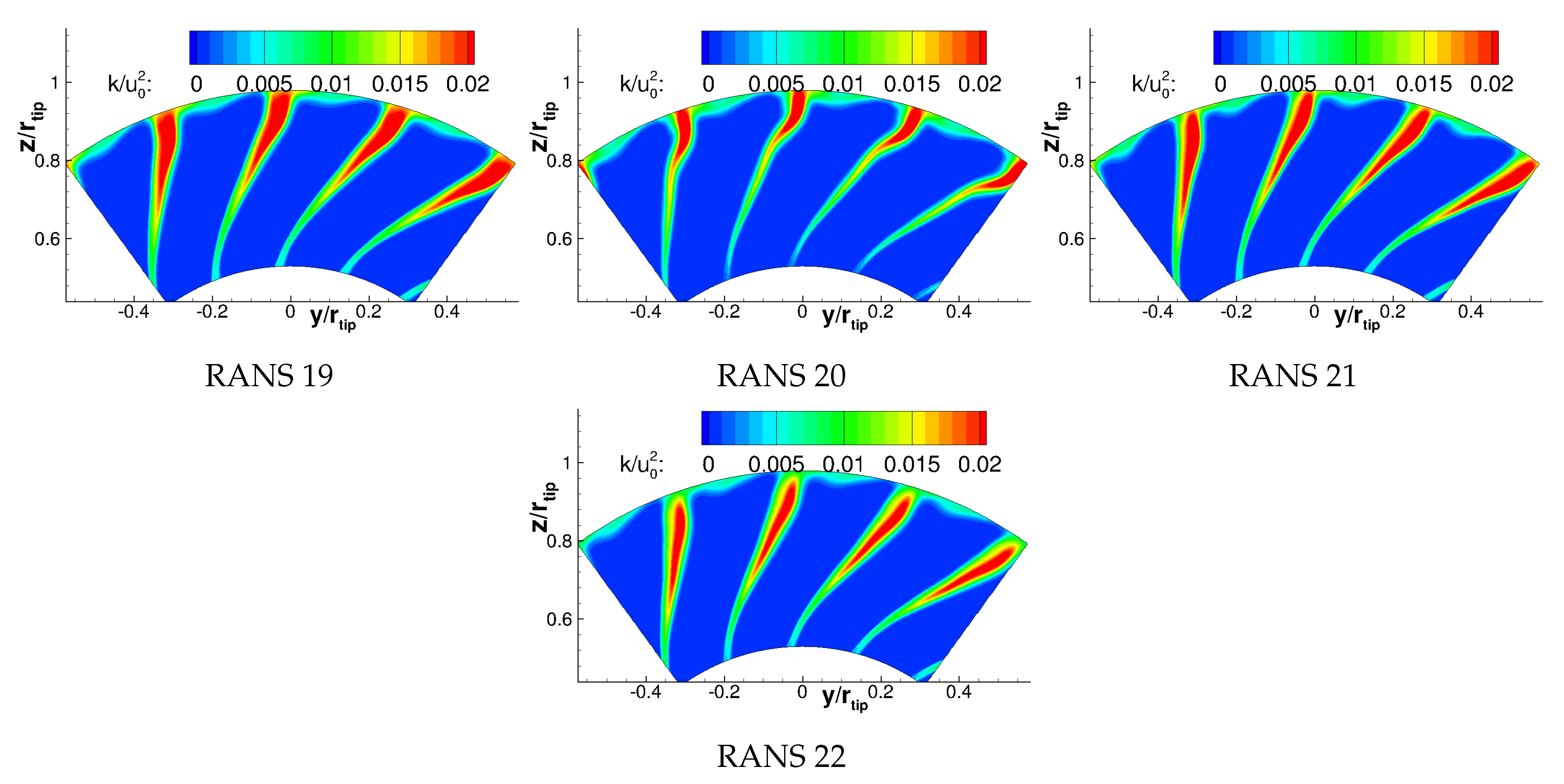
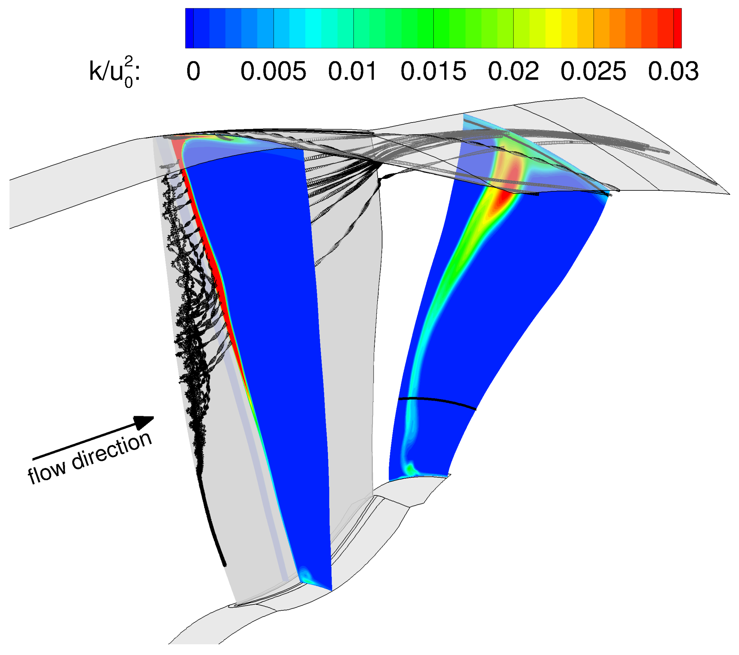
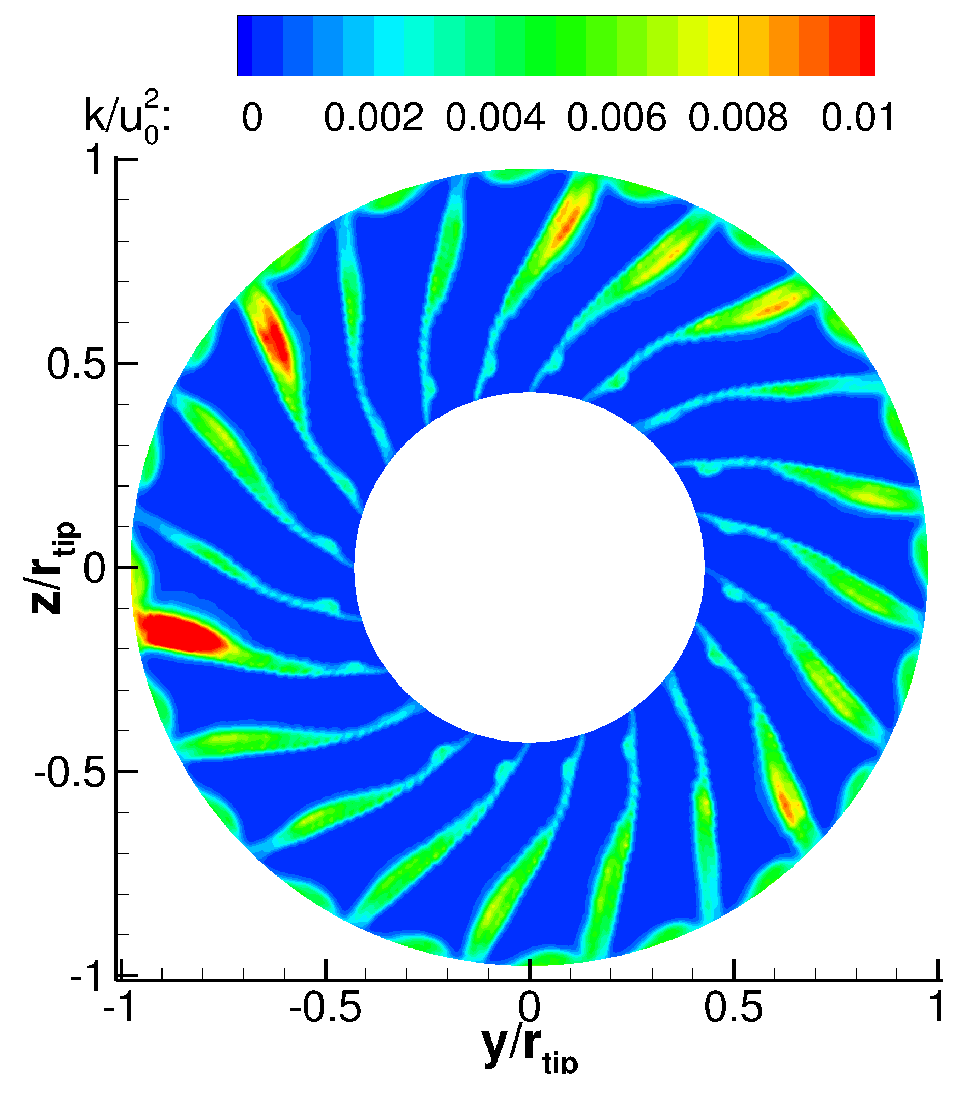
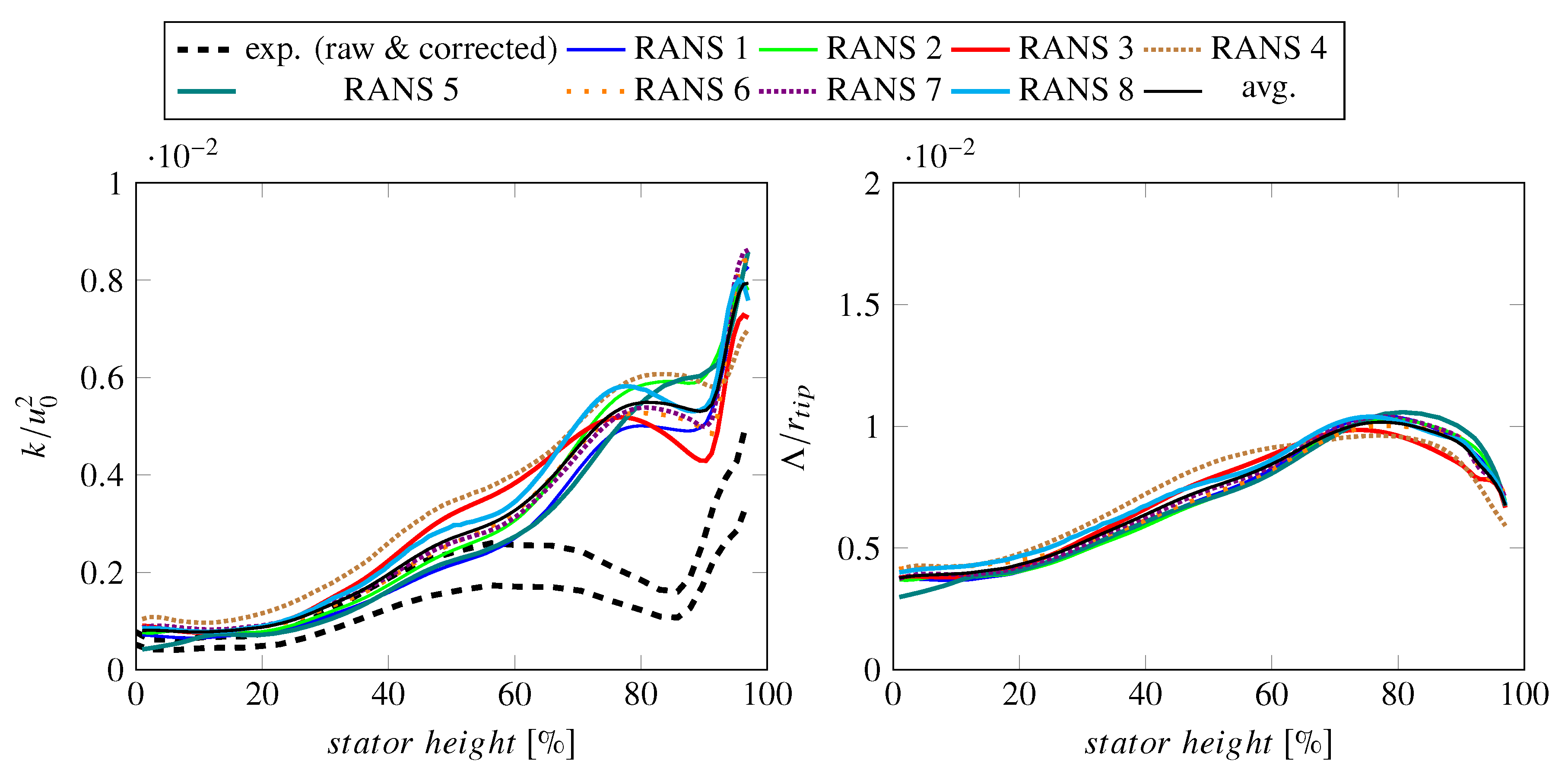
All RANS simulations using a Menter SST k- ω turbulence model predict a strong leading edge detachment causing vortical structures on the blade suction side, which is exemplarily shown in terms of streamlines and TKE contours in Figure 5. This flow phenomenon is particularly strong towards the tip wall and results in a strong production of turbulence and a pronounced wake deficit. The contour plots of the RANS simulations (RANS 1–8) at the HW 1 position therefore show large velocity deficits and high turbulent kinetic energies near the tip casing (see Figure A1, Figure A2, Figure A3 and Figure A4). A similar phenomenon was observed by Prasad and Prasad [48] and Arroyo et al. [49]. In the latter work, the strong leading edge detachment on the SDT fan was only predicted by the RANS simulation but not by the large eddy simulation. For the ACAT1 fan, a zonal detached eddy simulation using a Spalart-Allmaras turbulence model was performed by François et al. [50]. It does not predict a large leading edge separation as its turbulent intensity values near the fan tip are significantly lower than presented data extracted from a RANS simulation (denoted as RANS 5 in this paper) using a Menter SST k- ω turbulence model as shown by Polacsek et al. [51]. Conversely, the large eddy simulation performed by Lewis et al. [52] seems to show a significant flow detachment. A similar observation was made for an unsteady RANS simulation performed by Kissner et al. [53]. Figure 6 shows the non-dimensional turbulent kinetic energy levels measured by the hot-wire sensors and reveals a challenging property of this fan: The wakes are not homogeneous. The reason for this inhomogeneity is still subject for debate. However, most blades do not show significantly higher turbulence intensity levels near the tip casing, which would indicate the presence of an equally severe leading edge detachment in the experiment.
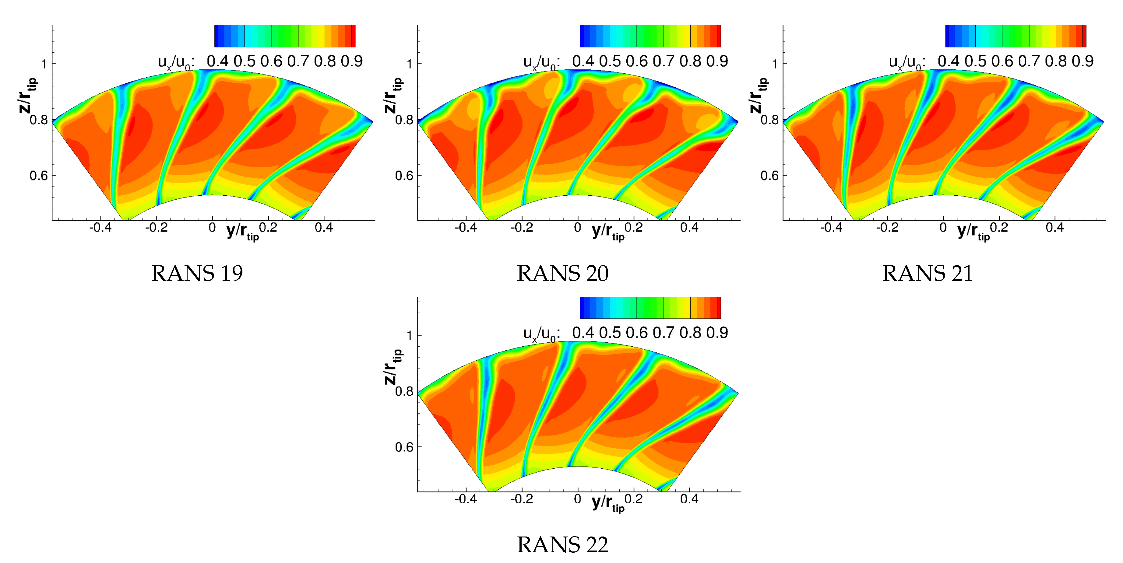
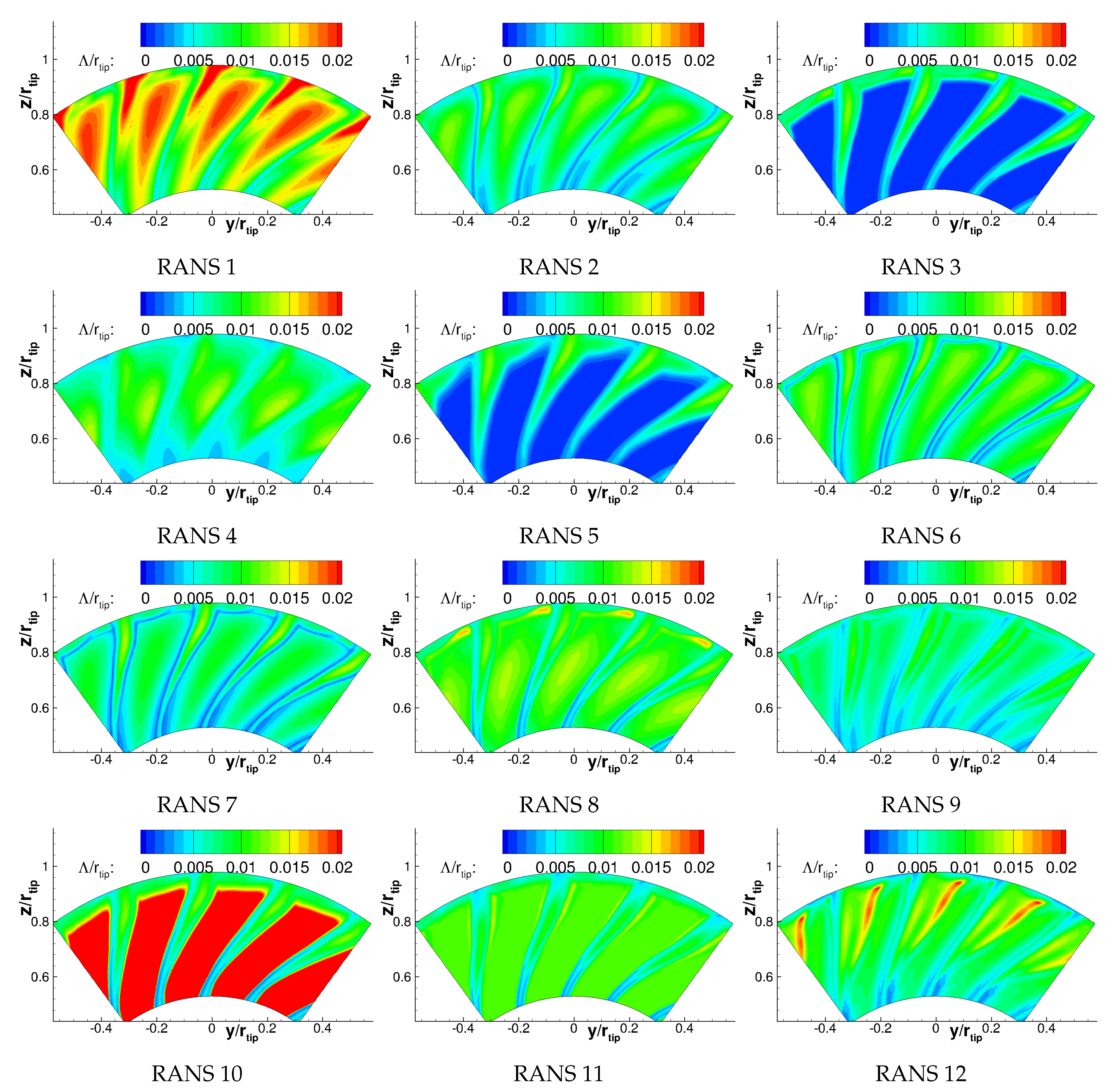
As unsteady phenomena such as flow detachments are challenging to predict using RANS simulations, it comes as no surprise that the wake structure of RANS simulations 1–8 show some local differences, particularly near the tip wall. This can be seen in the contours of flow velocities and turbulence characteristics (see Figure A1, Figure A2, Figure A3, Figure A4 and Figure A5). The overall wake structure is, however, still quite similar. An interesting feature of the contours shown at HW 1 position is the turbulent length scale outsides of the wakes, which vary drastically (see Figure A5). On the one hand, the blending function of the Menter SST k- ω turbulence model is known to fail if the turbulent length scale of the prescribed turbulence at the inlet is not small. This is the case for RANS simulations 1 and 2 causing the turbulent length scale between the wakes to differ significantly from prescribed length scales at the inlet. Other simulations may also encounter the same difficulty. On the other hand, the ingested turbulence, which reaches the rotor stage, is not comparable between the different simulations as different inlet turbulence intensities and intake lengths were used. If long intake lengths are used, the prescribed turbulence tends to decay quickly as there is no turbulence production in flows without mean flow gradients. However, the turbulent length scale between wakes is not critical for this case, as the wake turbulence is much greater than the ingested turbulence. Since the circumferentially averaged length scale was determined using a weighting by the turbulent kinetic energy, only the turbulent length scales in the wakes are important. Since the turbulent length scales within the wake are similar, the TKE-weighted, circumferentially averaged turbulent length scales are similar for all considered Menter SST k- ω simulations (see Figure 7).
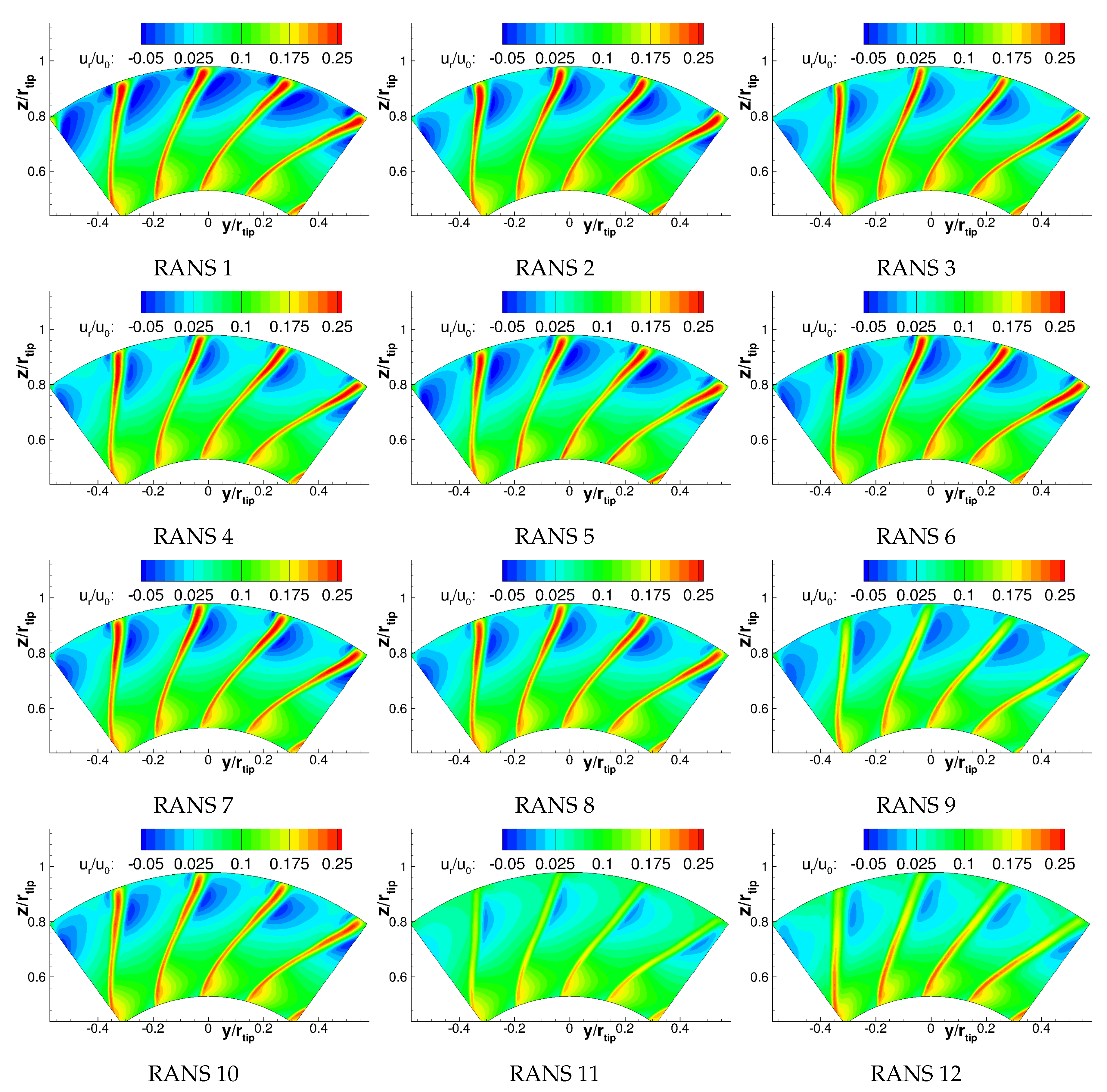
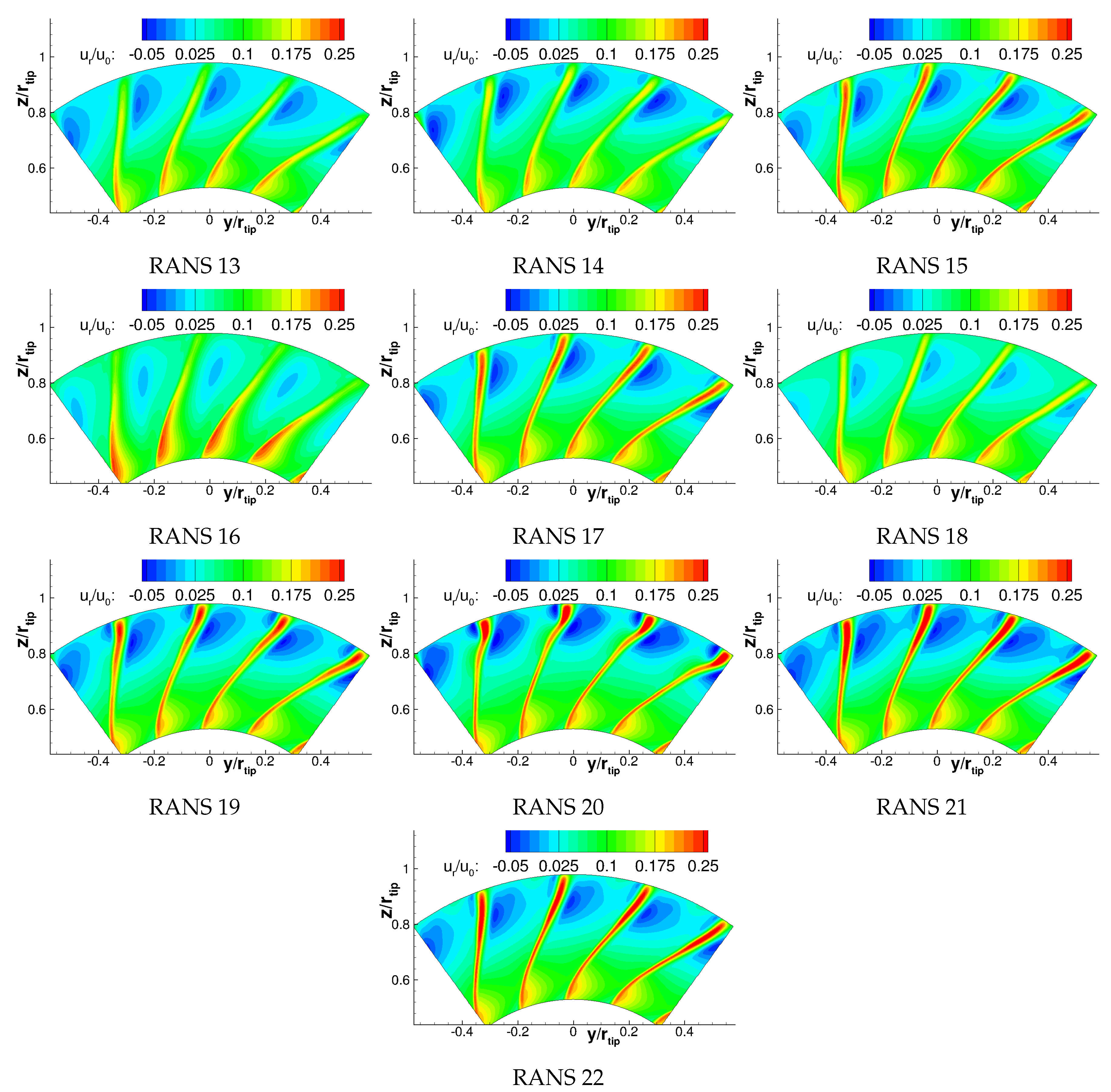
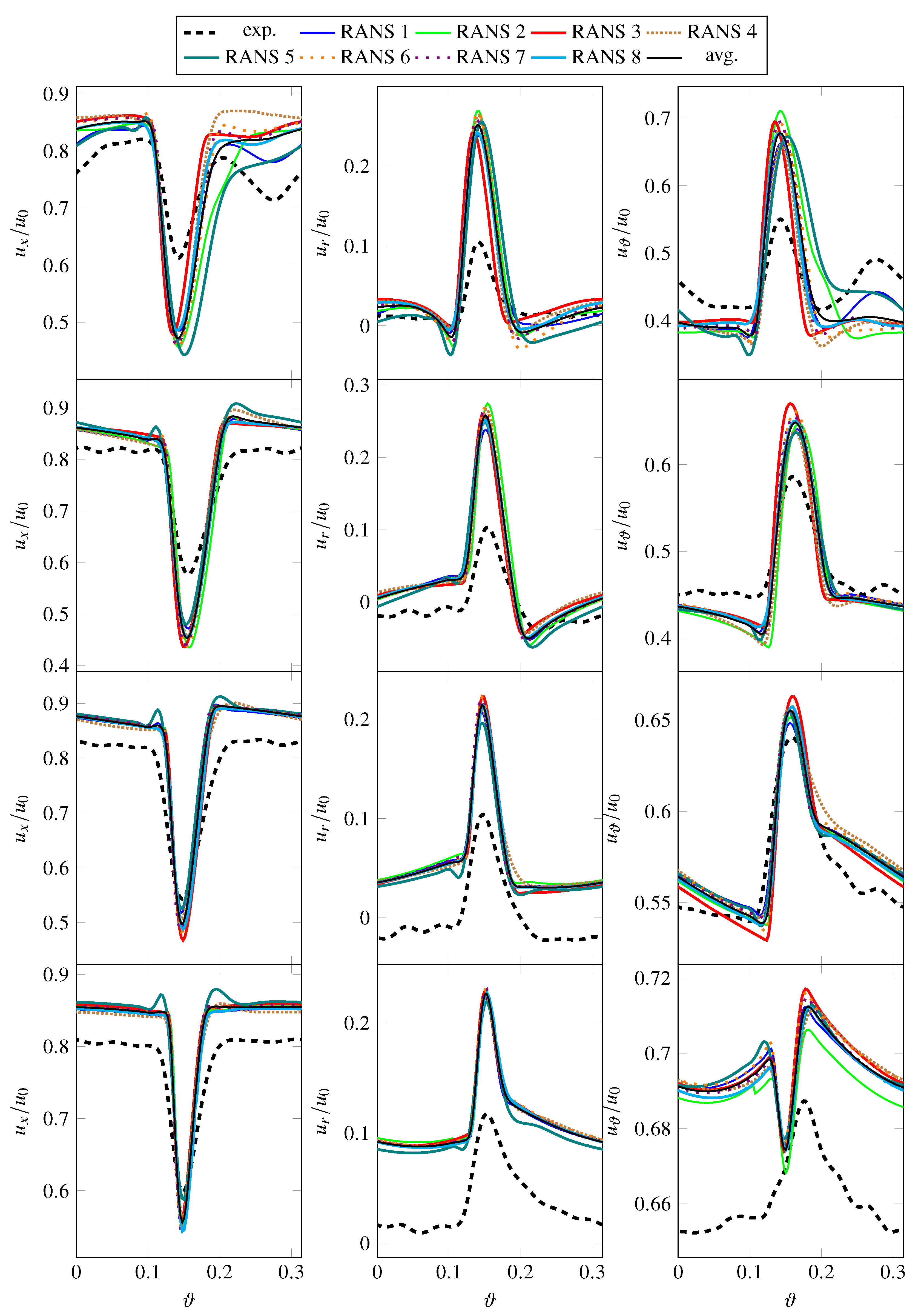
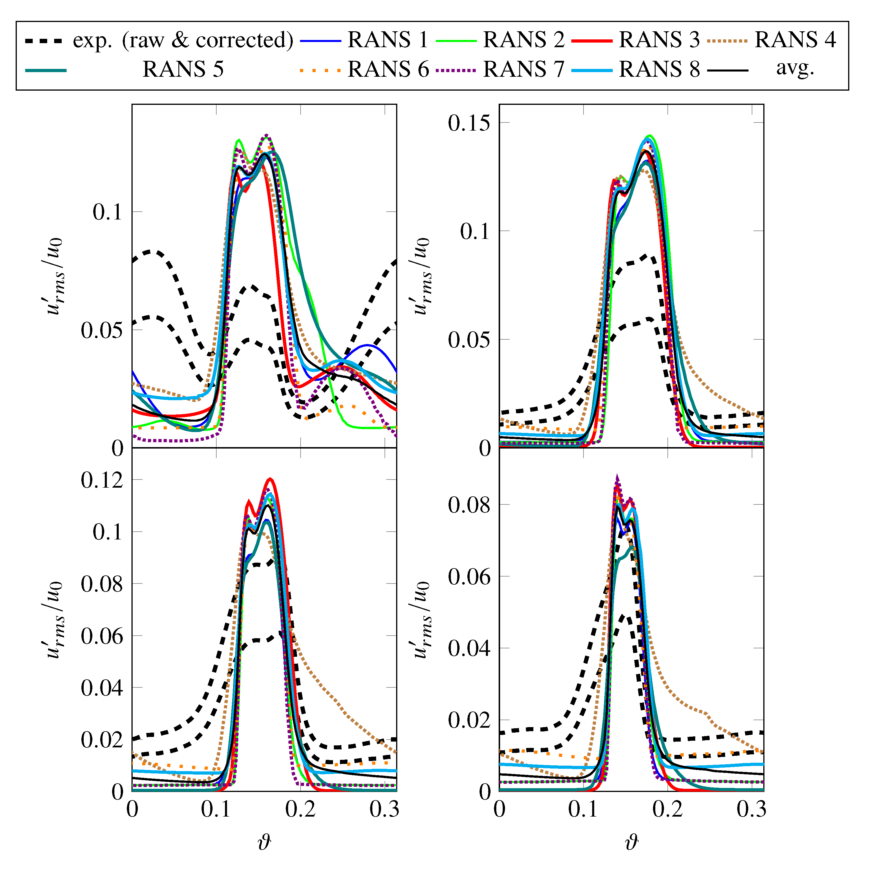
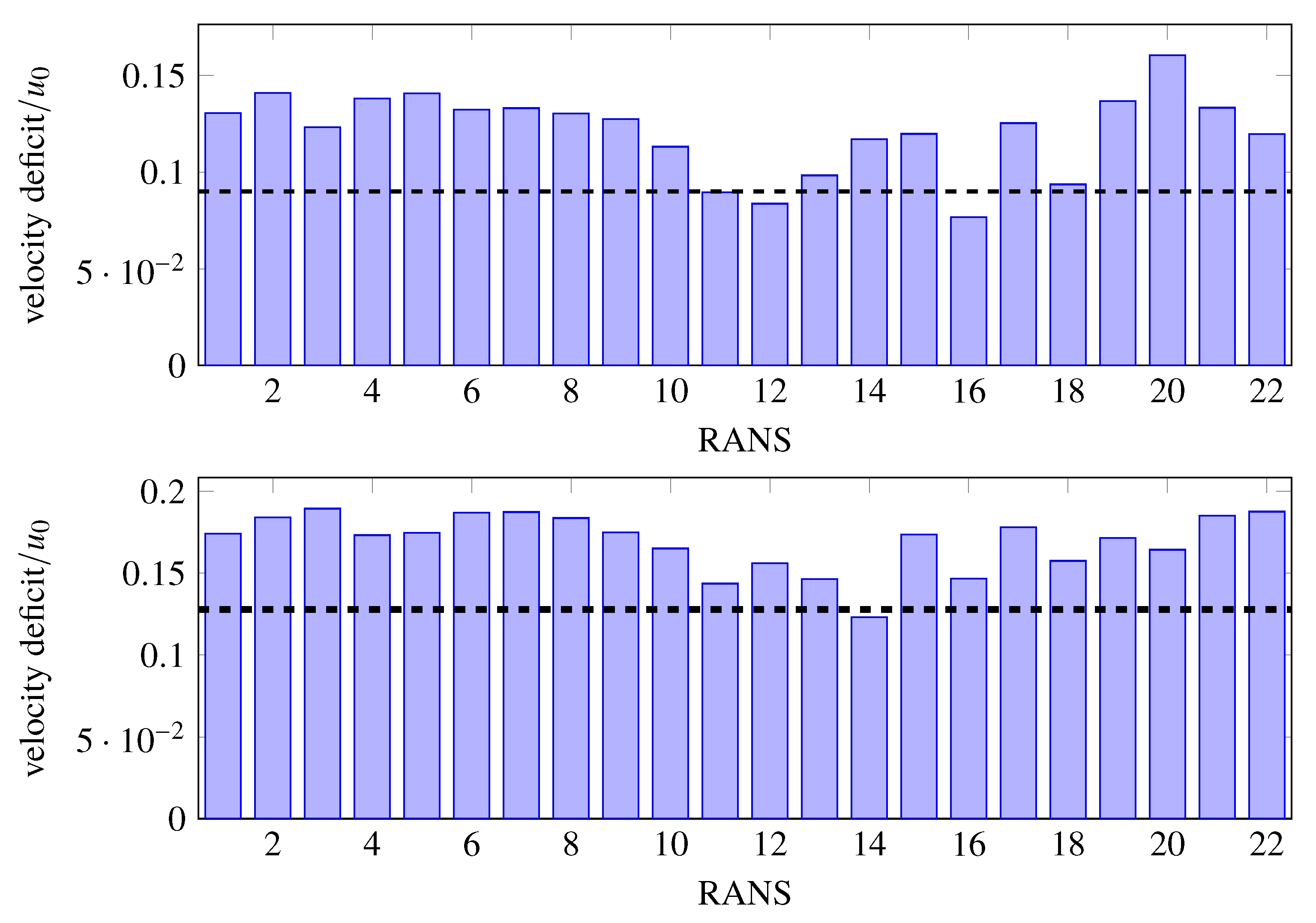
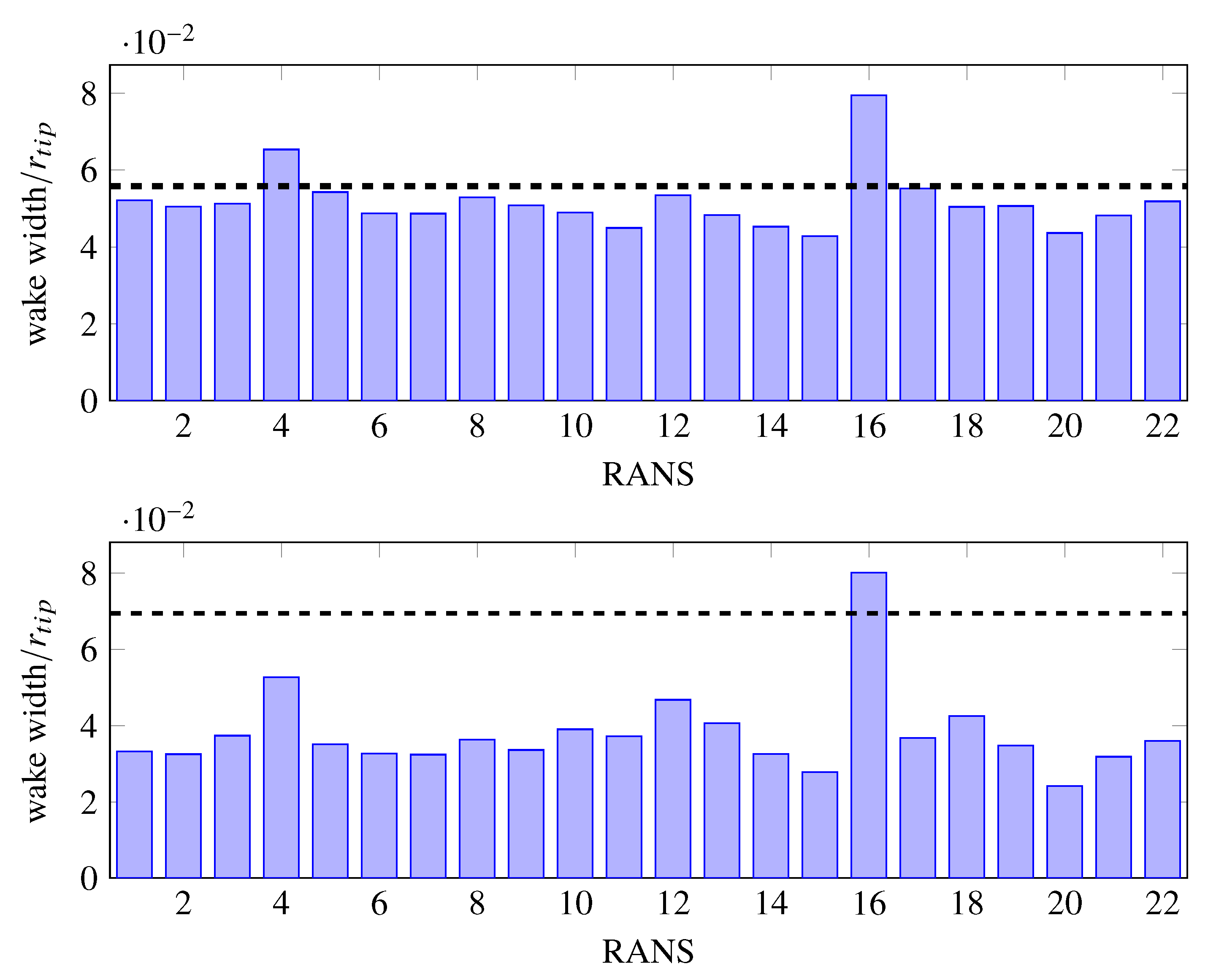
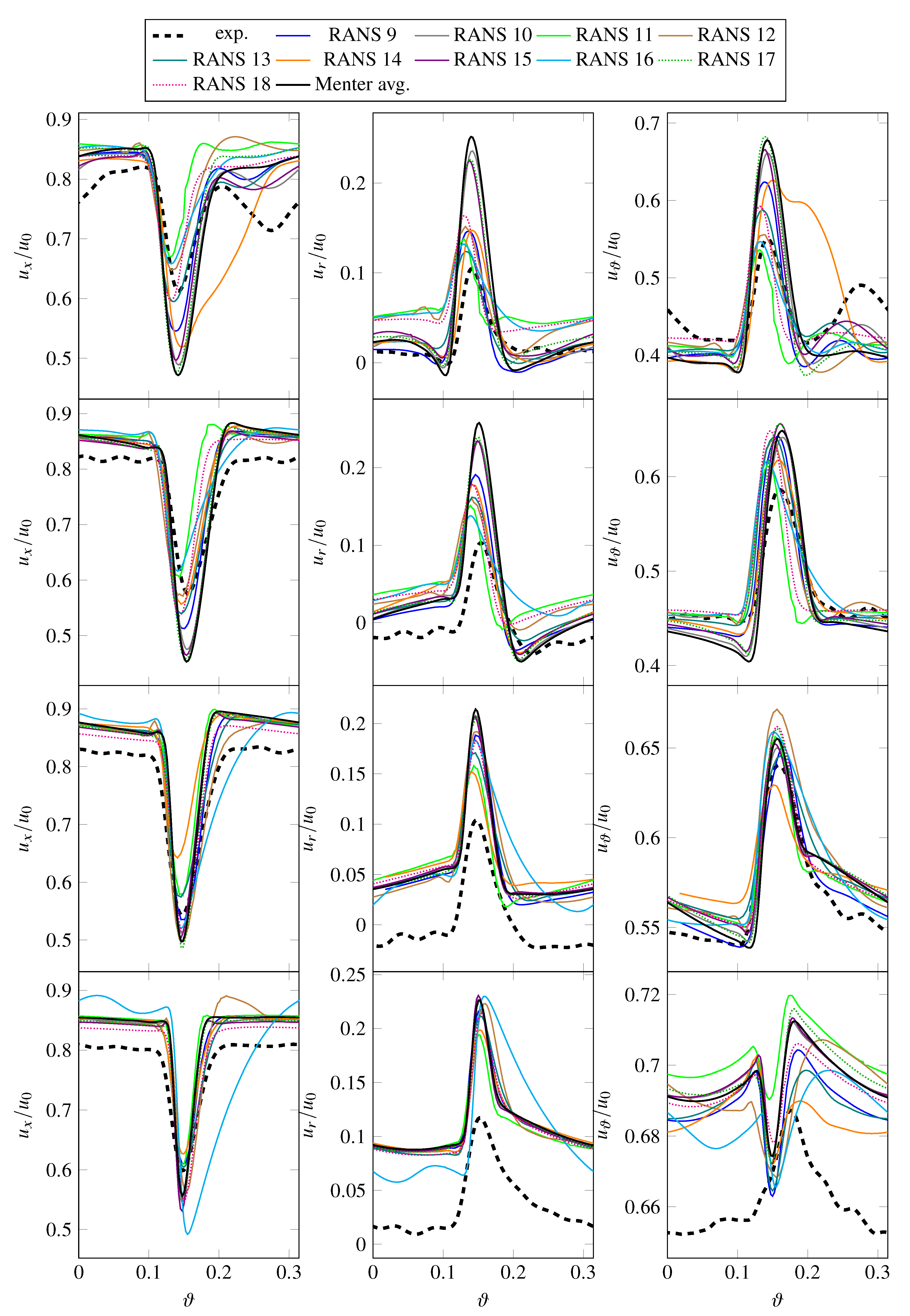
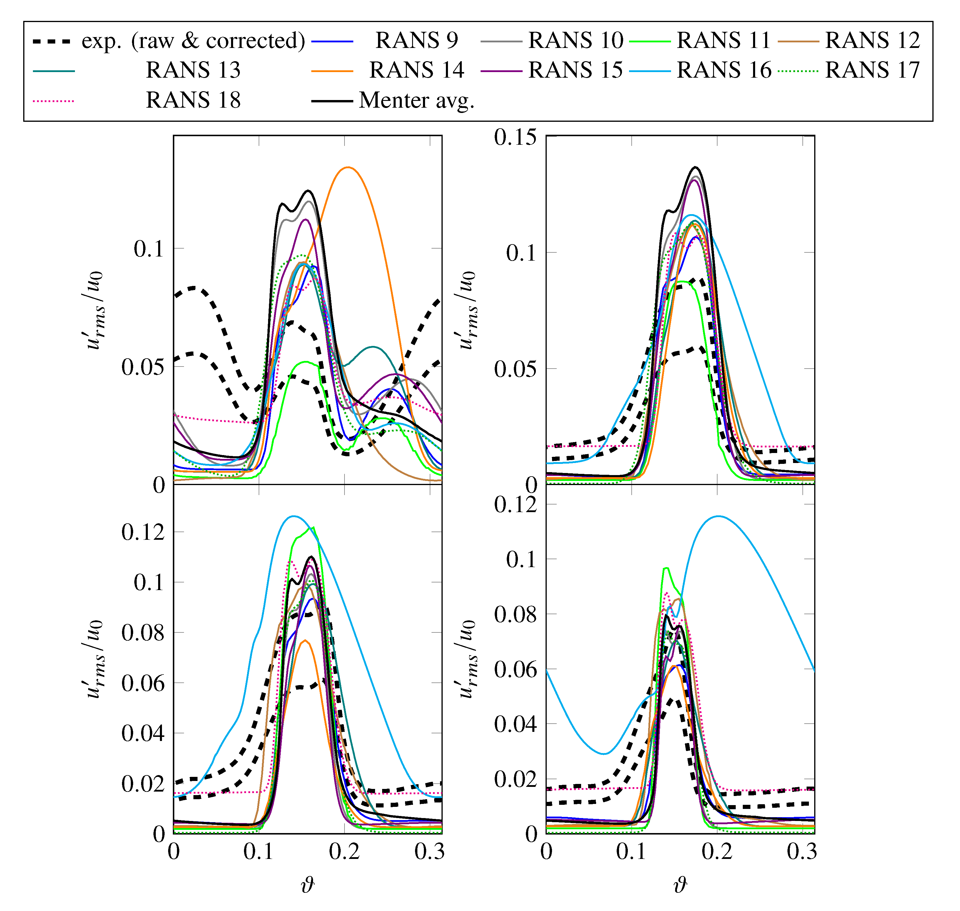
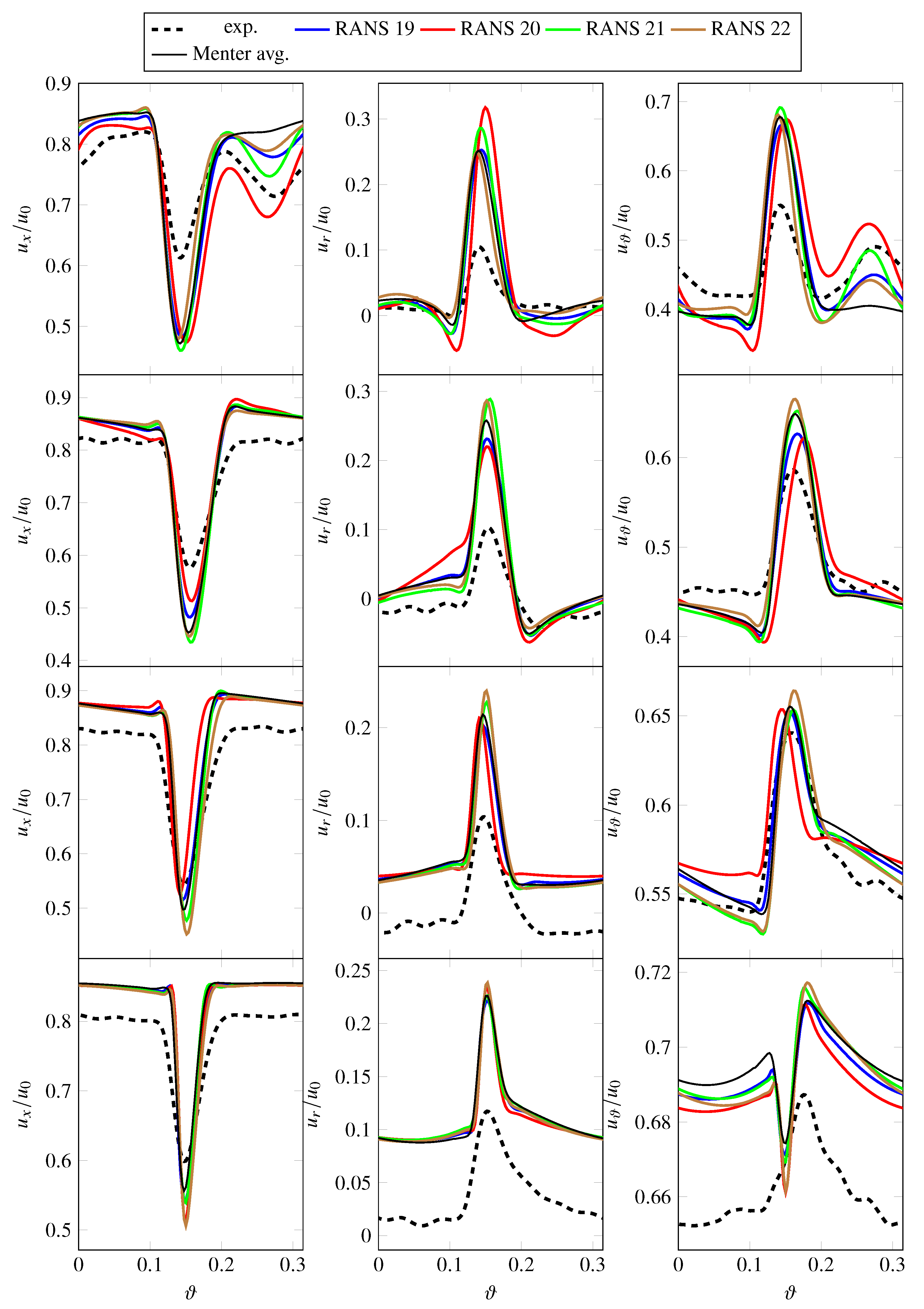
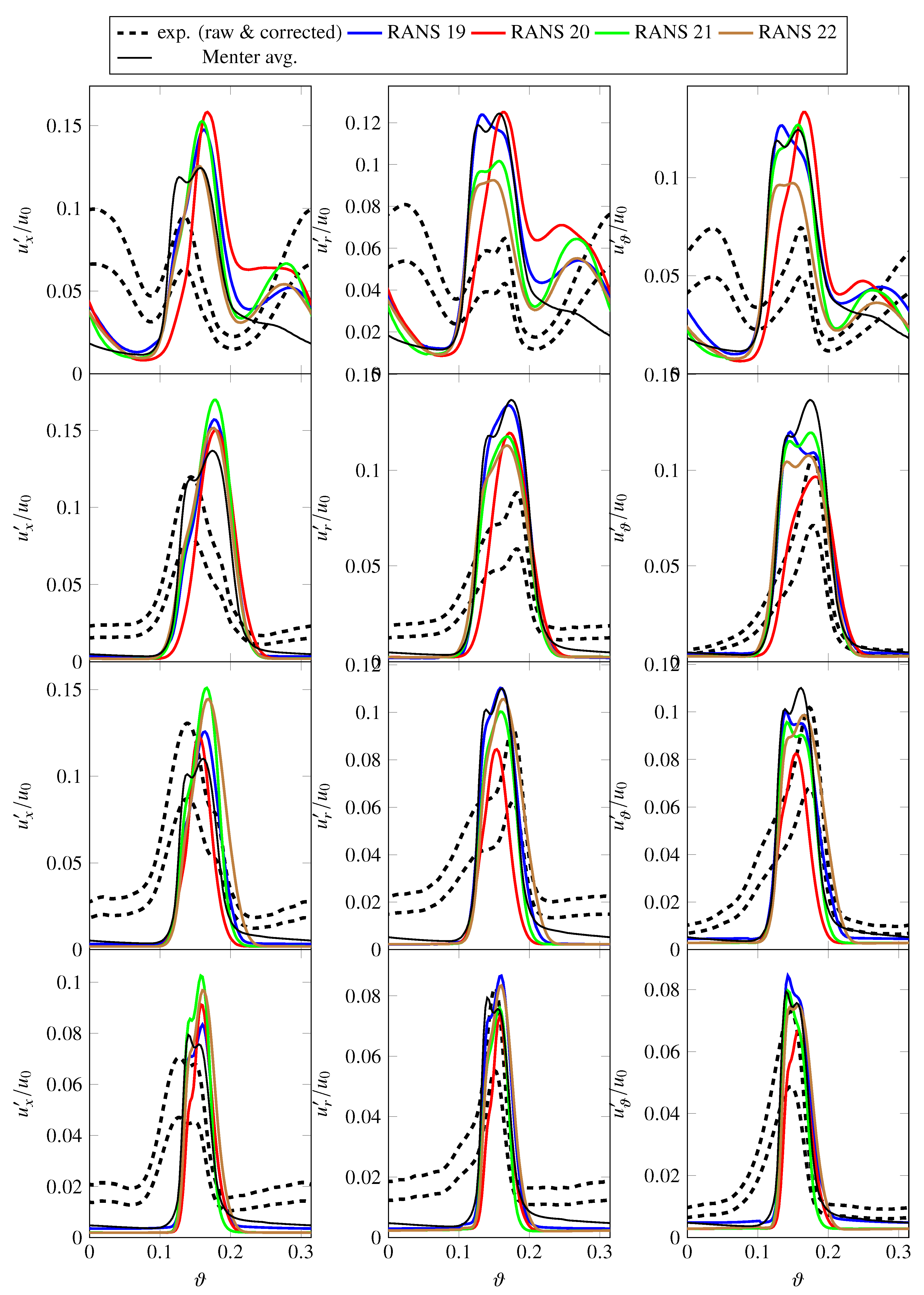
Mean and fluctuating velocities were extracted at four radial positions (90%, 75%, 50%, and 25% stator height) and compared to measured velocities as can be seen in Figure 8 and Figure 9. Overall, the extracted RANS velocities are similar. Some larger discrepancies in mean and root-mean-square velocities can be observed at the 90% position. While the depth of the wakes are comparable, the wake widths differ, which is a direct result of the sensitivity of the simulations to the flow separation at the rotor leading edges. In addition to the wake, some simulations have a second relative extremum at 90% stator height, which is likely caused by the tip vortex. To further describe the wake structures, wake deficits and wake widths were computed for simulated and experimental data. The wake deficits as shown in Figure 10 were computed as the difference between the mean total velocity and the minimum velocity in the wake. The wake widths as shown in Figure 11 were determined in terms of the turbulent kinetic energy by dividing the area of the wake by the maximum turbulent kinetic energy level within the wake. At 75% and 50% of the stator height, the wake velocity deficits of RANS simulations 1–8 do not show much variation, while the wake width computed for RANS 4 is a bit higher compared to the other simulations. This can be attributed to the flatter slope in TKE of RANS 4 compared to the other simulations. In general, the wake structure of RANS simulations 1–8 are similar in terms of velocities, wake velocity deficits, and wake widths.
When comparing the simulated to experimental wake data, several observations can be made:
  • The wake width is a bit larger in the experiment than in the simulations, especially at lower radial positions. One explanation for this phenomenon is that the hot-wire probes cover a measuring volume of 1 × 2 × 2 mm [10], which defines the spatial resolution. Therefore, the slope of the shear layers are “smeared” and wakes appear to be wider as they are in reality.
  • The wake velocity deficit is smaller in the experiment than in the simulations. Part of the reason for this offset is likely physical in nature. Particularly near the tip region, the wake velocity deficit in the experiment is less pronounced due to a less severe (or absent) leading edge flow detachment compared to the simulations, where it causes deeper and thicker wakes. Another part of the explanation may be due to the hot-wire measurement. The previously mentioned control volume can also cause flatter peaks. In addition, the hot-wire probes were calibrated at one radial position upstream of the rotor blades. Since the in-duct calibration was performed for circumferentially uniform flow, it can be expected that the calibration may not work as well within the wake as outside of it as the temperature increases inside the wakes.
  • There are some offsets in mean velocities outside of the wakes. Smaller offsets are indeed expected as the hot-wire probes are less accurate in measuring mean velocities as opposed to fluctuating velocities. Offsets in the radial velocity can occur if the yaw angle of an X-wire probe intended to measure axial and radial velocities is not well aligned with the mean flow. The circumferential velocity component then creates an additional cooling effect, which will be interpreted as partly axial and radial velocity. Since the radial component is significantly smaller than the axial and circumferential components, it is most susceptible to such an effect. The trends of the circumferential velocities at 25% of the stator height diverge, which may be due to the fact that the differences are quite small and likely difficult to capture.
  • Turbulent RMS velocities are overpredicted in the RANS simulations, particularly at 75% and 90% stator heights. It should be noted that there is some uncertainty regarding the measured fluctuating velocities. The lower, experimental line in Figure 9 are values directly determined from the measured data, while the upper line includes a factor of 1.5. The thickness of the hot-wires reduces the frequency resolution of the measured data. In this case, the cut-off frequency (or resolution limit) was a posteriori estimated to be around 7–8 kHz. Polacsek et al. [51] have introduced a correction factor of 1.5, which was determined by extrapolating the measured levels beyond the cut-off limit relative to the results of a scale-resolving simulation. For this reason, the raw as well as the corrected experimental values are shown in subsequent figures featuring either turbulent kinetic energies or RMS velocities. It should again be highlighted that the hot-wire calibration may be less suited for determining values within the wake than outside of the wake. Part of the observed offset in RMS velocities may, however, be physical as the higher turbulence levels in the RANS simulations are probably caused by a larger separation at the rotor leading edge than in the experiment. At 90% of the stator height, the measured values also capture the structure of the tip vortex resulting in two peaks.
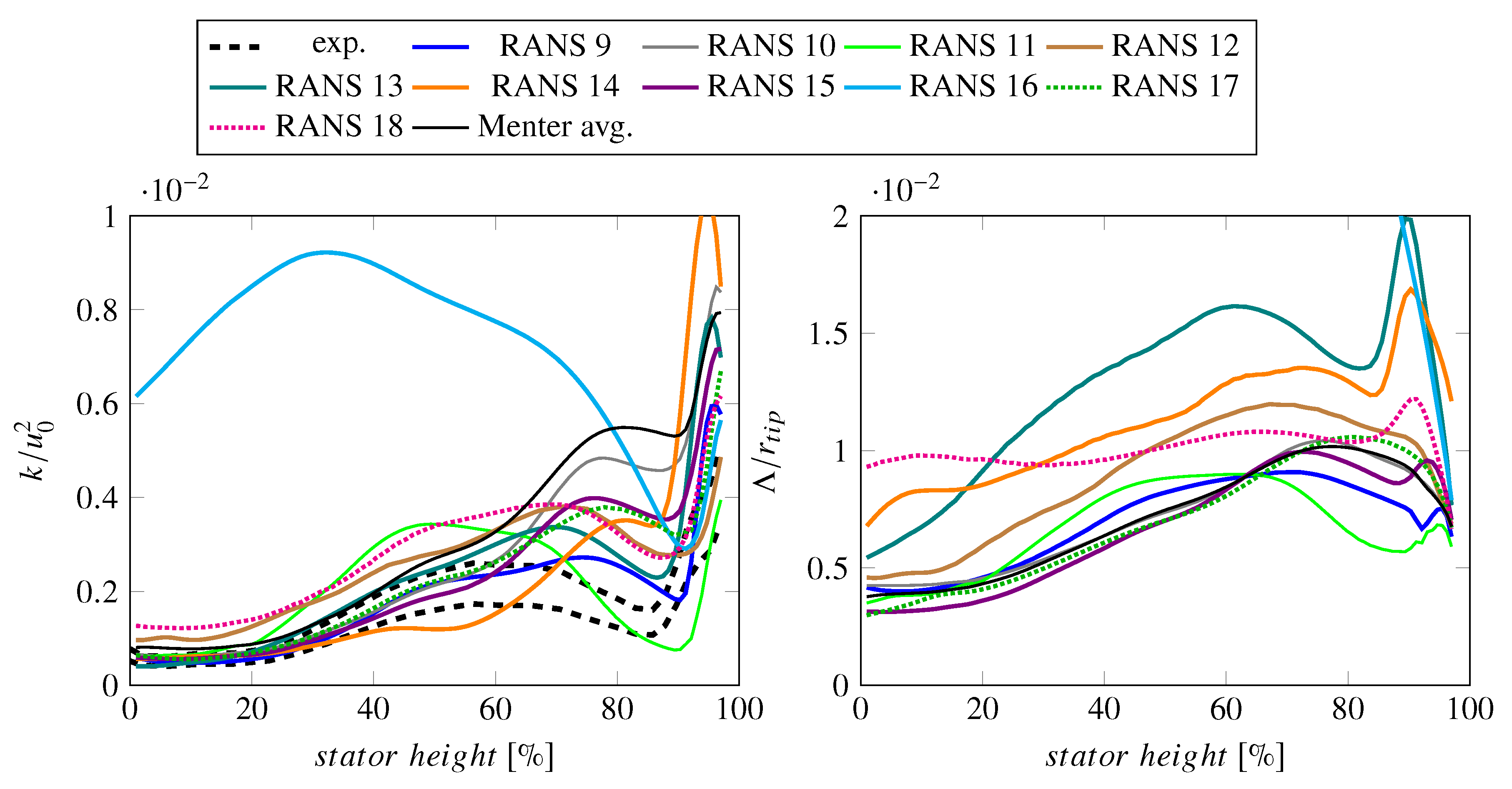
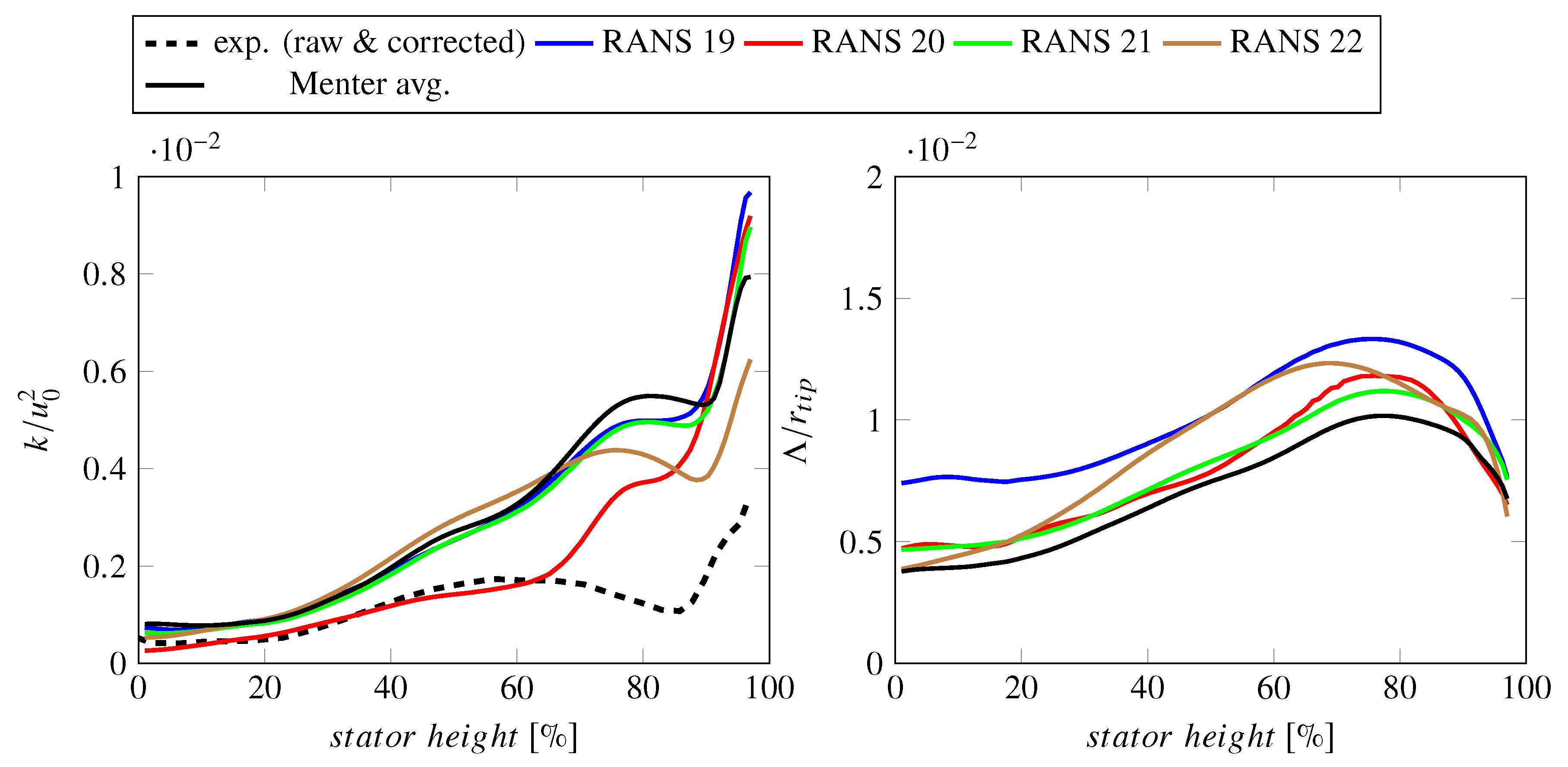
Despite some smaller differences in the wake structures, the circumferential averages of turbulent kinetic energies (TKE) and turbulent length scales (TLS) are in good agreement for all RANS Menter SST k- ω simulations (see Figure 7). As observed regarding the wakes in terms of RMS velocities, the circumferentially averaged TKE values close to the tip casing are higher than in the experiment by up to a factor of 3.
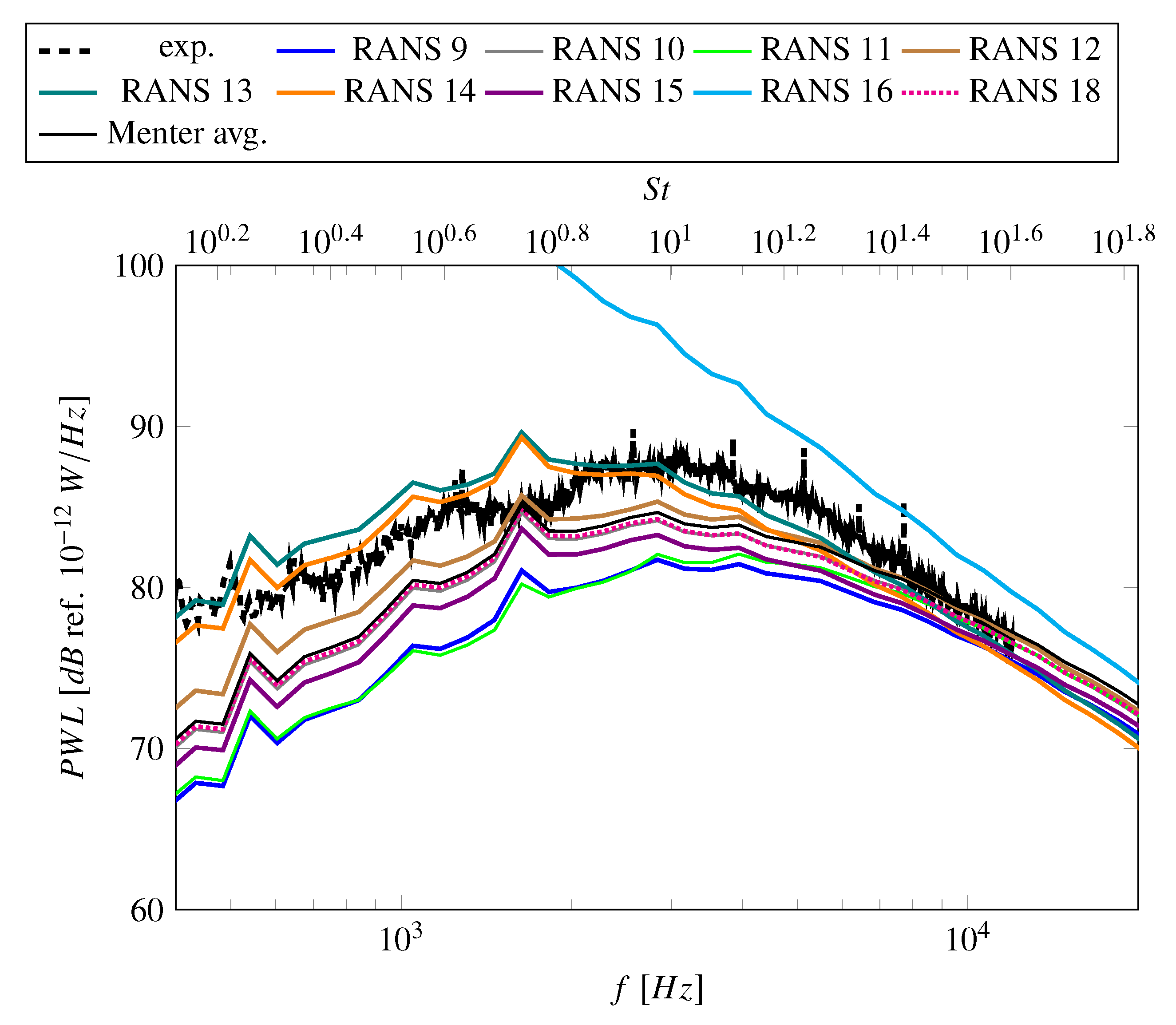
As the circumferentially averaged turbulence characteristics are similar, the predicted fan broadband noise levels converge to nearly the same solution (see Figure 12). The simulations are therefore consistent, yet the predicted sound power levels downstream of the fan stage underestimate the experimentally determined sound power levels, especially at low frequencies. The underprediction of sound power levels has been documented for analytical methods [1,2,40], synthetic turbulence methods [54,55,56], and scale-resolving methods [51]. One explanation may be that the experimental sound power levels are not restricted to fan broadband noise levels but also include other noise sources. Particularly at lower frequencies, the self-noise of the testing facilities is thought to be significant.
No trend with respect to the mesh resolution or CFD codes can be observed in the circumferentially averaged turbulence characteristics and predicted fan broadband noise levels. For example, RANS 1 and 2 were conducted using identical settings, except that a finer mesh was used for RANS 2. There are only small differences in the turbulence characteristics, but barely any differences in sound power levels. In general, finer meshes yield similar results as coarser grids. Nonetheless, it should be noted that all of the meshes were designed by turbomachinery experts and boundary layers and wakes were well resolved in all simulations. The authors postulate that there would be a mesh dependencies if meshes were too coarse to capture critical flow features. The solutions are also independent of the chosen CFD solver. It means that the Menter SST k- ω turbulence model was likely implemented similarly in all codes.

3.2. Influence of Linear Eddy Viscosity Turbulence Models

Linear eddy viscosity models are the most commonly used models by industry but also in a scientific context for turbomachinery applications. For the ACAT1 fan at approach operating conditions, the following two-equation turbulence models were used: Menter SST k- ω , Wilcox k- ω , and Smith k-l. In the last section, the results of simulations using the standard formulation of the Menter SST k- ω turbulence model without any modifications were analyzed. In this section, all other linear eddy viscosity models and their model modifications (RANS 9–18) are discussed.
RANS simulations 9–11 applied a Menter SST k- ω turbulence model. RANS 10 uses a simplified formulation of the production term. Its production term is formulated in terms of the vorticity rather than the shear stress. This modification ensures that the ratio between the specific dissipation rate and the turbulent kinetic energy is conserved resulting in the conservation of the prescribed turbulent length scale between the wakes in the interstage region (see Figure A5). Since the wake turbulence is dominant for the investigated case, the modified production terms and the higher turbulent length scales between the wakes have negligible impact on mean and RMS velocities and circumferentially averaged turbulence characteristics compared to the standard Menter SST formulation (see Figure 13, Figure 14 and Figure 15). Therefore, the alternative production term formulation has no impact on the predicted sound power level spectra as it is nearly identical to the average of the Menter SST k- ω simulations (see Figure 16). Boussinesq-based turbulence models typically produce too much turbulent kinetic energy at stagnation points unless non-equilibrium flows are specifically considered in the model formulation. As previously described, the Menter SST k- ω turbulence model applies a simple limiter in non-equilibrium flow domains like stagnation points, which reduces the turbulence production. The limiter also causes the model to have a tendency to amplify flow separation. Despite the fact that the turbulence model inherently contains a stagnation point fix, sometimes additional measures are taken to further reduce the turbulence production. RANS 9 and 11 both applied a Kato-Launder modification but note that the implementation is different. For RANS 11, the production term is modified in the entire flow regime while for RANS 9, the altered production term formulation is only applied under certain conditions. Note that RANS 11 also uses a vortex-based, local fix for rotational effects. This further impacts the solution, particularly near the fan tip casing. Compared to Menter averages, both RANS 9 and 11 have reduced levels of turbulent kinetic energy—at least in some regions of the flow—due to the reduced turbulence production in the stagnation point of the rotor blades (see Figure 14 and Figure 15). However, the drop in turbulent kinetic energy of RANS 11 is significantly larger towards the tip casing and the circumferentially averaged turbulent length scale also drops, which could also be an effect of the rotational fix. The rotational fix also causes significant changes in the wake velocities (again mostly closer to the tip wall), the wake velocity deficits as well as mean velocities within the wake match more closely with experimental data (see Figure 10 and Figure 13). Since velocities were set to be constant for the fan broadband prediction, all changes in predicted sound power levels can be attributed to changes in the turbulence characteristics and the sound power levels of RANS 9 and 11 are similar as shown in Figure 16. Due to the decrease in turbulence production in non-equilibrium flows caused by the Kato-Launder modification, the overall level of turbulent kinetic energy decreases and therefore the sound power levels decrease as well. The difference at low frequencies is about 4 dB. RANS 12 uses a highly modified Menter SST k- ω formulation, which was optimized to be used in an industrial context. Similar to RANS 11, the wake velocities are closer to the experimental data near the tip wall compared to the averages of standard Menter formulations. RANS 12 also predicts lower turbulent kinetic energies near the tip casing but it differs in predicting larger overall turbulent length scales (see Figure 15). This causes a slight increase in sound power levels compared to the Menter average. As an increased turbulent length scale causes an additional shifting of the spectrum towards lower frequencies, the difference of up to 1.5 dB is largest at low frequencies and therefore, the agreement with experimental values is slightly better.
RANS simulations 13–16 used a Wilcox k- ω turbulence model. RANS 13 and 14 both used a Kato-Launder modification, while RANS 14 also used a γ R e ϑ t transition model. When looking at the axial velocities and turbulent kinetic energies at the HW 1 position (see Figure A1 and Figure A4), the interaction between the tip vortex and the boundary layer seems to be stronger when a transition model is applied. In fact, Figure 14 shows that the peak in the RMS velocity has shifted at 90% stator height, which indicates that the turbulent kinetic energy of the tip vortex/boundary layer interaction is dominant at this position compared to the contribution of the wake. The turbulent kinetic energy at most radial positions (except near the tip) as well as the turbulent length scale is smaller when applying a transition model as can be seen in Figure 15, which causes the sound power levels to be lower when a transition model is applied. Compared to the Menter averages, the sound power levels are up to 8 dB higher and the frequency peak is shifted towards a lower frequency. While the agreement with experimental values is better in terms of the power amplitude, the agreement in spectral shape is worse as the frequency peaks do not match. RANS simulations 15 and 16 used different stagnation point fixes to compensate that the Wilcox k- ω model was formulated under the assumption of equilibrium flow. The Kato-Launder modification of RANS 16 yields unrealistic results in terms of the wake structure. The failure of the simulation is less severe for the velocities but leads to unrealistically high turbulent kinetic energies and turbulent length scales. These turbulence characteristics lead to extremely high sound power levels. While the turbulence settings for RANS 13 and 16 are nominally the same, the implementation of the Kato-Launder modification is different. The Kato-Launder modification alters the production term for the entire simulation domain for RANS 15, while the alternative production term is only used under certain conditions for RANS 13. RANS 15 uses a Schwarz limiter, which limits the specific dissipation rate in non-equilibrium flows instead of altering the transport equations of the turbulence model as is the case for the Kato-Launder modification. Compared to RANS 13, the simulated velocities of RANS 15 are much closer to the Menter averages. The circumferentially averaged turbulent kinetic energy is also lower, especially near the tip wall, which suggests that the flow separation is less severe. The circumferentially averaged turbulent length scale is comparable to the Menter average and therefore significantly lower than for RANS 13. The sound power levels are therefore slightly lower than the Menter averages (due to the reduced TKE) and much lower than the results of RANS 13 due to the difference in TLS. It is not clear from these results whether the differences between RANS simulations 13 and 15 can be explained by the different types of stagnation fixes or if the implementation of the Wilcox k- ω turbulence model itself is also different.
The Smith k-l turbulence model was used for RANS simulations 17 and 18. Unfortunately the chosen turbulence settings of RANS 17 does not enable the computation of an integral turbulent length scale using Pope’s definitions. Therefore, the results cannot be included in the comparison of sound power levels. The difference in simulation setups could also explain some observed differences between the simulations. The velocities computed by RANS 17 are closer to the Menter averages, while the velocities of RANS 18 are closer to the experimental results (see Figure 13). The turbulent kinetic energies near the tip wall are smaller than the Menter averages for both simulations (Figure 15). However, the turbulent length scales of RANS 18 are higher than the Menter averages, particularly at lower radial positions. The reduction in TKE and the increase in TLS cause the sound power levels to be nearly identical to Menter-averaged sound power levels (see Figure 16).

3.3. Influence of More Advanced Turbulence Models

RANS simulations 19–22 used more advanced turbulence models. RANS 19 was performed using the Hellsten EARSM k- ω turbulence model, which is a non-linear eddy viscosity model. RANS 20–22 were performed using three different Reynolds stress models: Wilcox stress- ω (RANS 20), SSG/LRR- ω (RANS 21), and JH stress- ω h (RANS 22).
As Figure 17 shows, the velocities of all four simulations are quite close to the Menter averages. The experimental RMS velocities are only slightly anisotropic, where the axial values are slightly higher than the circumferential and radial values (see Figure 18). While the turbulence models mirror this trend, the RMS velocities are overpredicted, particularly at 90% stator height. The magnitude of the RMS velocities are similar to the Menter results. Unlike most simpler RANS simulations, all turbulence models have a second peak at 90% stator height due to the interaction of the tip vortex with the boundary layer. The circumferentially averaged turbulent kinetic energies of RANS 19 and 20 are nearly identical to the Menter averages (see Figure 19). They rely on two models closely related to the Menter SST k- ω : All three models (Menter SST k- ω , Hellsten EARSM k- ω , SSG/LRR- ω ) use the same transport equation for the specific dissipation rate and the blending function. The Hellsten EARSM k- ω has an additional non-linear, anisotropic term in the Boussinesq hypothesis. Therefore, certain similarities in results are expected. The additional anisotropic term of the Hellsten EARSM k- ω is particularly high in the shear layers of the wake and causes the turbulent length scales to increase, while the length scales of the SSG/LRR- ω model are similar to the Menter values. RANS 20 (Wilcox stress- ω ) produces lower levels of TKE near the tip wall, which is similar to the RANS simulations using the closely related Wilcox k- ω model. The circumferentially averaged TLS are, however, similar to the Menter values. The turbulent length scales of RANS 22 (JH stress- ω h ) lie between the Menter and the Hellsten values. They reach their highest levels at mid span. The circumferentially averaged TKE levels are only quite similar to the Menter values.
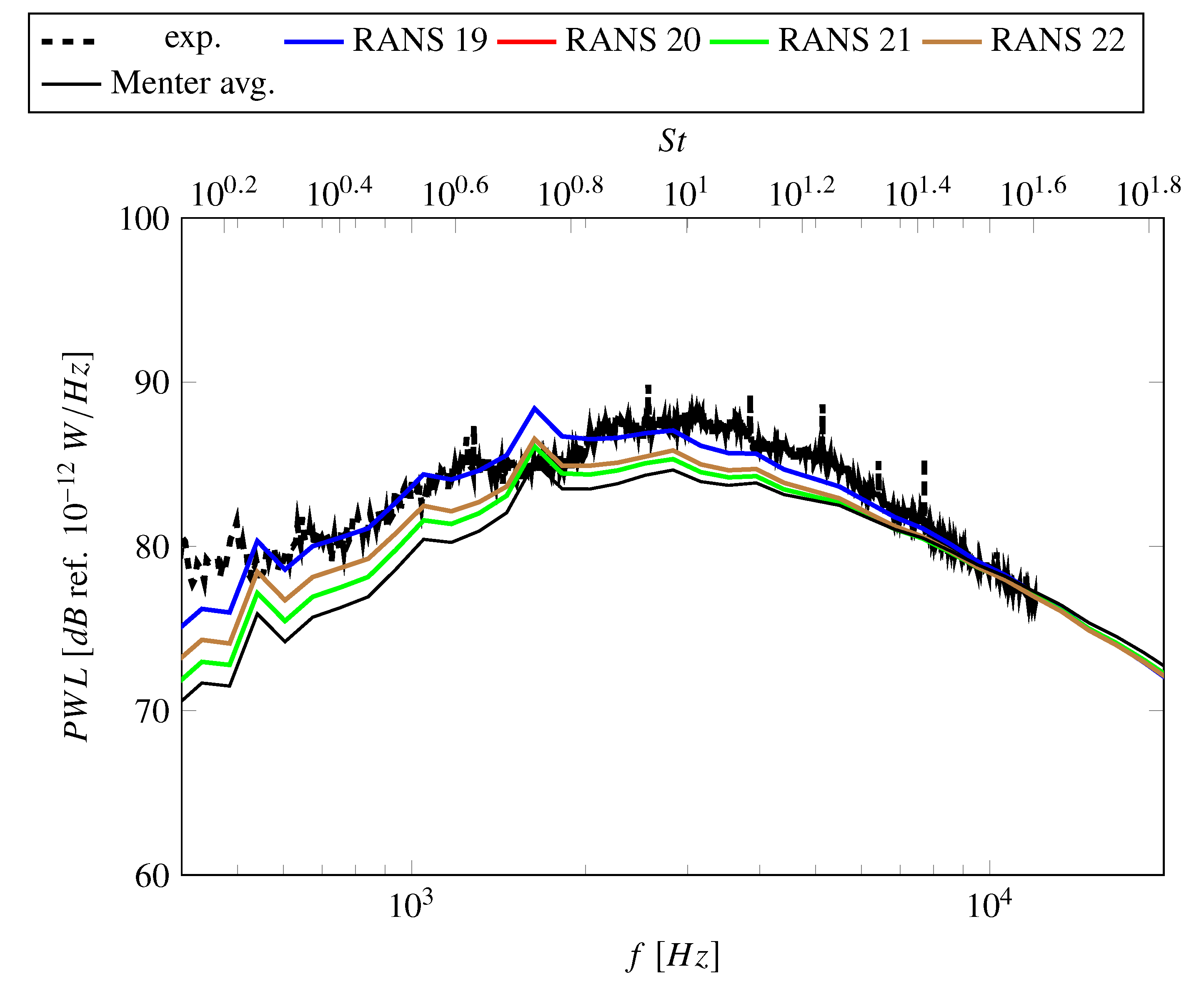
The sound power levels predicted using inputs from RANS 19 (Hellsten EARSM k- ω ) are higher by up to 5 dB than the Menter-averaged sound power levels as shown in Figure 20. In fact, the predicted levels match well with experimental data. RANS 22 (JH stress- ω h ) also produced higher sound power levels compared to Menter values due to the higher turbulent length scales. RANS simulations 20 and 21 produce nearly identical sound power levels, which are only marginally higher than for Menter SST simulations.

4. Conclusions

RANS-informed analytical methods are commonly used for predicting fan broadband noise. The accuracy of these predictions depend not only on the acoustic model itself but also on the used RANS input and the processing of these RANS inputs. In this paper, uncertainties related to the RANS inputs were analyzed using an extensive data set of 22 RANS simulations. These simulations were performed by turbomachinery experts from several different companies and research institutions. Different codes, simulation meshes, and turbulence settings were used to perform simulations for the ACAT1 fan at approach conditions. To avoid uncertainties related to the processing of RANS data such as the extrapolation of turbulence and flow characteristics from the evaluation plane to the position of the stator leading edges and the circumferential averaging of integral turbulent lengths scales, a standard procedure was applied for preparing the RANS inputs. In addition, the same acoustic model was used for predicting the fan broadband noise downstream of the stator vanes. The RANS data were analyzed by comparing the wakes structures in terms of mean and fluctuating velocities, circumferentially averaged turbulence characteristics, and predicted sound power levels.
This study showed that the choice of turbulence model settings is the most critical influencing parameter regarding turbulence and flow characteristics as well as predicted fan broadband noise. Other RANS settings and even the mesh design were not important. Note that all simulations were performed by experts, who chose reasonable RANS settings and designed adequate meshes. The chosen operating point of the ACAT1 fan is a particularly challenging case for RANS simulations as it is quite off-design. While most RANS simulations predict a flow separation at the rotor leading edges, hot-wire measurements show that such a strong flow separation is likely not present or significantly less severe in the experiment. Nonetheless, using these RANS simulations to predict fan broadband noise typically leads to an underprediction of the sound power levels determined from measured data. It should be added that the experimental sound power levels contain other broadband noise sources besides rotor-stator-interaction noise, so that it can be expected that predicted levels are lower than measured values. In addition, it should be kept in mind that analytical models simplify a complex, physical problem to compute fan broadband noise in an efficient manner. Nonetheless, the discrepancy between hot-wire and acoustic measurements are a conundrum for CFD users: Measures reducing the flow separation at the rotor leading edge to achieve a better agreement with hot-wire data increase the offset between predicted and measured broadband noise levels. Measures to augment fan broadband noise in order to achieve a better agreement with experimental noise values increase the offset between simulated data and hot-wire measurements. Nevertheless, some recommendations based on the results of the benchmark can be made:
  • The Menter SST k- ω turbulence model and related turbulence models (like the Hellsten EARSM k- ω or the SSG/LRR- ω ) tend to exaggerate flow separations leading to increased turbulence production. This leads to an increase of sound power levels leading to a better agreement with measured sound power levels but increases the offset between simulated and measured velocities. The Hellsten EARSM k- ω also causes an increase in turbulent length scale, which is advantageous in terms of sound power levels.
  • The Smith k-l turbulence model predicts a weaker flow separation resulting in a better agreement with hot-wire measurements. Due to an increase in predicted TLS, the predicted sound power levels are similar to sound power levels predicted using a Menter SST k- ω turbulence model. For the investigated case, the Smith k-l turbulence model may be the best compromise between matching hot-wire and acoustic measurements.
  • The use of differential Reynolds stress models did not improve results in terms of flow and turbulence characteristics and in terms of fan broadband noise. Unless the objective is to study anisotopic turbulence in more detail, simpler models should be used as they are more robust and require less computational resources.
  • Stagnation fixes need to be used for turbulence model featuring an equilibrium formulations. For other turbulence models, stagnation fixes further reduce turbulence production. The reduction of turbulence production leads to a further reduction of predicted fan broadband noise leading to a worse agreement with measurements. The use of stagnation fixes does not significantly improve the agreement with hot-wire data. If the use of stagnation point is necessary, a simple limiter or a local modification of transport equations limited to areas of non-equilibrium flows are preferable.
  • Rotational fixes can be used to achieve a better agreement between hot-wire measurements and simulated velocities.
  • The use of transition model does not improve fan broadband noise predictions or the agreement with hot-wire measurements.
There likely is no ideal solution for simulating complicated, unsteady flow phenomena, which can occur at a fan’s off-design operating point, with a RANS technique. Nonetheless, the fan broadband noise was reasonably well predicted by many RANS simulations. While the levels were mostly underpredicted (as should likely be expected), the spectral shape and peak frequency were correctly captured using most RANS inputs. This is encouraging as it shows—as do the results of the second part of this benchmark [1]—that trends can satisfactorily be predicted using a simple RANS-informed analytical method.

Author Contributions

Conceptualization, C.K. and S.G.; Data curation, C.K., S.G. and P.S.; Formal analysis, C.K., S.G. and P.S.; Investigation, C.K., S.G. and P.S.; Methodology, C.K. and S.G.; Resources, C.K., S.G., M.B., P.C., P.C.L., H.d.L., B.F., K.L., D.L., G.M.V. and T.N.-L.; Software, C.K., S.G., M.B., P.C., P.C.L., H.d.L., B.F., K.L., D.L., G.M.V. and T.N.-L.; Supervision, C.K. and S.G.; Validation, C.K., S.G., M.B., P.C., P.C.L., H.d.L., B.F., K.L., D.L., G.M.V. and T.N.-L.; Visualization, C.K.; Writing—original draft, C.K.; Writing—review & editing, C.K., S.G., M.B., P.C., P.C.L., H.d.L., B.F., K.L., D.L., G.M.V.and T.N.-L. All authors have read and agreed to the published version of the manuscript.

Funding

The presented work was conducted in the frame of the project TurboNoiseBB, which has received funding from the European Union’s Horizon 2020 research and innovation program under grant agreement No. 690714.

Acknowledgments

The authors would like to thank the following people for their support and advice: Niklas Andersson (Chalmers), Marc Jacob (ECL), Stéphane Moreau (ECL), Christian Morsbach (DLR), Cyril Polacsek (ONERA), Jesús Pueblas (ITP Aero), David Radford (Rolls-Royce), and Adolfo Serrano (ITP Aero).

Conflicts of Interest

The authors declare no conflict of interest.

Nomenclature

The following symbols are used in this manuscript:
Awake area, m 2
C Re Reynolds number-dependent constant
C μ turbulence model-dependent constant
dwake velocity deficit, m/s
ffrequency, Hz
kturbulent kinetic energy, m 2 /s 2
L w wake width, m
lpseudo turbulent length scale (Smith), m
P W L sound power level, dB ref. 10 12 W/Hz
r t i p averaged tip rotor radius, 0.428 m
R e ϑ t transition Reynolds number based on the momentum thickness
S i j mean strain rate tensor, 1/s
S t Strouhal number
uvelocity, m/s
u 0 total mean velocity at the HW 1 position, 128 m/s
γ intermittency
ϵ turbulent dissipation rate, m 2 /s 3
ϑ angle, rad
Λ integral turbulent length scale, m
μ T eddy viscosity, m 2 /s
ρ density, kg/m 3
τ i j Reynolds stress tensor, kg/(s 2 m)
Φ i i turbulence velocity frequency spectrum (relative to direction i), m 2 /s
Ω i j vorticity tensor, 1/s
ω specific turbulent dissipation rate, 1/s
ω h specific homogeneous dissipation rate, 1/s

Abbreviations

The following abbreviations are used in this manuscript:
ACAT1AneCom AeroTest Rotor 1
CFDComputational Fluid Dynamics
DNSDirect Numerical Simulation
DRSMDifferential Reynolds Stress Model
EARSMExplicit Algebraic Reynolds Stress Model
HWHot-Wire
ISAInternational Standard Atmosphere
JHJakirlic-Hanjalic
LELeading Edge
LRRLaunder-Reece-Rodi
NASANational Aeronautics and Space Administration
PWLSound Power Level
RANSReynolds-Averaged Navier-Stokes
RMSRoot Mean Square
RSIRotor-Stator-Interaction
TETrailing Edge
TKETurbulent Kinetic Energy
TLSTurbulent Length Scale
SDTSource Diagnostic Test
SSGSpeziale-Sarkar-Gatski
SSTShear-Stress-Transport
UFFAUniversal Fan Facility for Acoustics

Appendix A. Velocities

Figure A1. Comparison of axial velocities at HW 1 position.
Acoustics 02 00029 g0a1aAcoustics 02 00029 g0a1b
Figure A2. Comparison of radial velocities at HW 1 position.
Acoustics 02 00029 g0a2aAcoustics 02 00029 g0a2b
Figure A3. Comparison of circumferential velocities at HW 1 position.
Acoustics 02 00029 g0a3aAcoustics 02 00029 g0a3b

Appendix B. Turbulence Characteristics
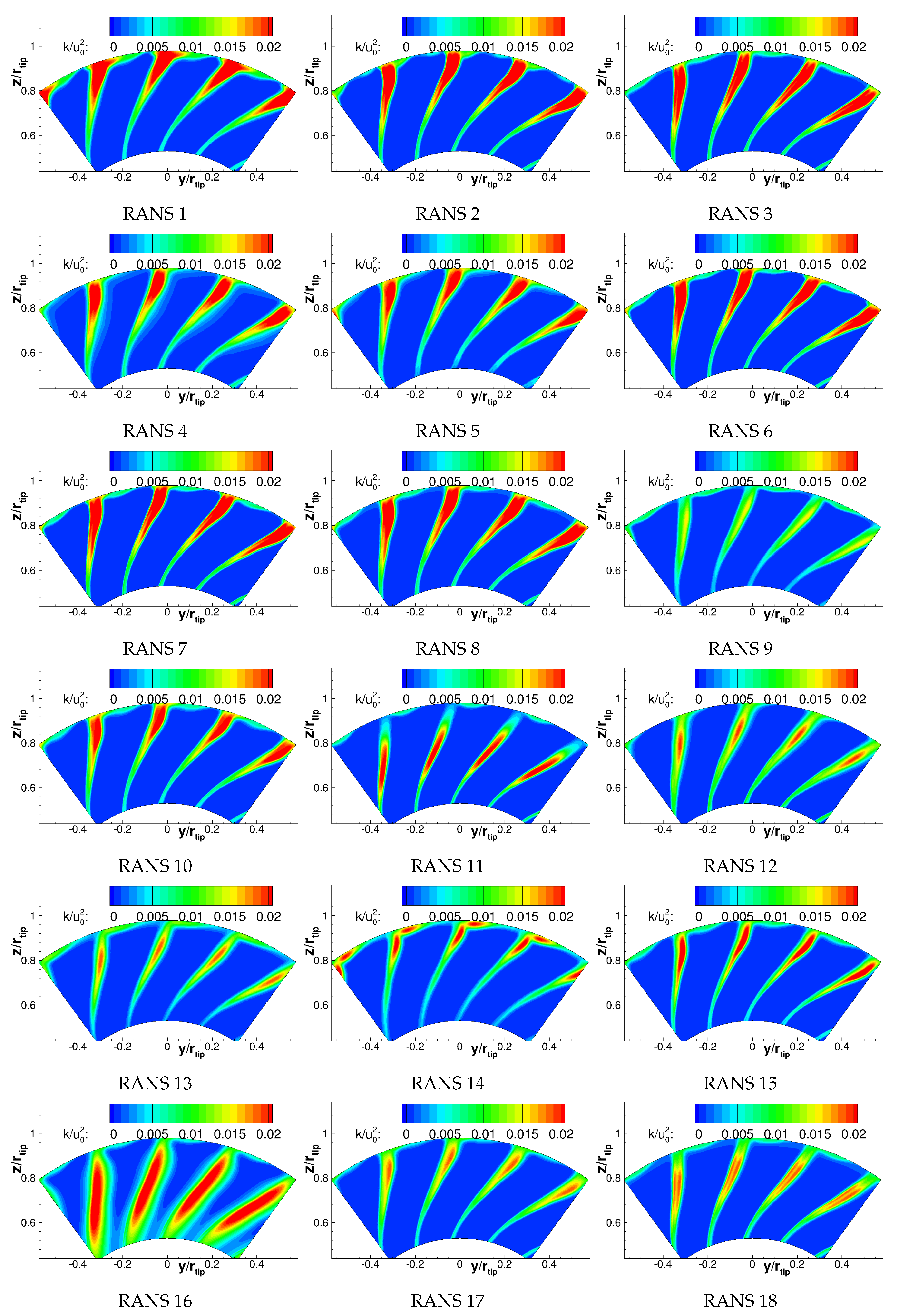
Figure A4. Comparison of turbulent kinetic energies at HW 1 position.
Acoustics 02 00029 g0a4aAcoustics 02 00029 g0a4b
Figure A5. Comparison of turbulent length scales at HW 1 position.
Acoustics 02 00029 g0a5aAcoustics 02 00029 g0a5b

References

  1. Guérin, S.; Kissner, C.; Seeler, P.; Blazquez Navarro, R.A.; Carrasco Laraña, P.; de Laborderie, H.; Lewis, D.; Paruchuri, C.; Polacsek, C.; Thisse, J. ACAT1 Benchmark of RANS-informed Analytical Methods for Fan Broadband Noise Prediction: Part II—Influence of the Acoustic Models. Acoustics 2020. in review. [Google Scholar]
  2. Guérin, S.; Kissner, C.A.; Kajasa, B.; Jaron, R.; Behn, M.; Pardowitz, B.; Tapken, U.; Hakansson, S.; Meyer, R.; Enghardt, L. Noise prediction of the ACAT1 fan with a RANS-informed analytical method: Success and challenge. In Proceedings of the 25th AIAA/CEAS Aeroacoustics Conference, Delft, The Netherlands, 20–23 May 2019. [Google Scholar] [CrossRef]
  3. Grace, S.; Maunus, J.; Sondak, D.L. Effect of CFD Wake Prediction in a Hybrid Simulation of Fan Broadband Interaction Noise. In Proceedings of the 17th AIAA/CEAS Aeroacoustics Conference, Portland, OR, USA, 5–8 June 2011. [Google Scholar] [CrossRef] [Green Version]
  4. Maunus, J.; Grace, S.; Sondak, D.; Yakhot, V. Characteristics of turbulence in a turbofan stage. J. Turbomach. 2013, 135. [Google Scholar] [CrossRef]
  5. Ventres, C.S.; Theobald, M.A.; Mark, W.D. Turbofan Noise Generation. Volume 1: Analysis; Technical Report; Bolt Beranek and Newman Inc./NASA: Cleveland, OH, USA, 1982.
  6. Nallasamy, M.; Envia, E. Computation of rotor wake turbulence noise. J. Sound Vib. 2005, 282, 649–678. [Google Scholar] [CrossRef]
  7. Jaron, R.; Herthum, H.; Franke, M.; Moreau, A.; Guérin, S. Impact of Turbulence Models on RANS-Informed Predicition of Fan Broadband Interaction Noise. In Proceedings of the 12th European Turbomachinery Conference (ETC), Stockholm, Sweden, 3–7 April 2017. [Google Scholar]
  8. Jaron, R. Aeroakustische Auslegung von Triebwerksfans mittels multidisziplinärer Optimierungen. Ph.D. Thesis, TU Berlin, Berlin, Germany, 2018. [Google Scholar] [CrossRef]
  9. Moreau, A. A Unified Analytical Approach for the Acoustic Conceptual Design of Fans of Modern Aero-Engines. Ph.D. Thesis, TU Berlin, Berlin, Germany, 2017. [Google Scholar] [CrossRef]
  10. Meyer, R.; Hakansson, S.; Hage, W.; Enghardt, L. Instantaneous flow field measurements in the interstage section between a fan and the outlet guiding vanes at different axial positions. In Proceedings of the 13th European Conference on Turbomachinery Fluid Dynamics and Thermodynamics, Lausanne, Switzerland, 8–12 April 2019. [Google Scholar]
  11. Tapken, U.; Pardowitz, B.; Behn, M. Radial mode analyis of fan broadband noise. In Proceedings of the 2017, 23rd AIAA/CEAS Aeroacoustics Conference, Denver, CO, USA, 5–9 April 2017. [Google Scholar] [CrossRef]
  12. Behn, M.; Pardowitz, B.; Tapken, U. Separation of tonal and broadband noise components by cyclostationary analysis of the modal sound field in a low-speed fan test rig. In Proceedings of the Fan2018, Darmstadt, Germany, 18–20 April 2018. [Google Scholar]
  13. Joseph, P.; Morfey, C.L.; Lowis, C.R. Multi-mode sound transmission in ducts with flow. J. Sound Vib. 2003, 264, 523–544. [Google Scholar] [CrossRef]
  14. Tapken, U.; Behn, M.; Spitalny, M.; Pardowitz, B. Radial mode breakdown of the ACAT1 fan broadband noise generation in the bypass duct using a sparse sensor array. In Proceedings of the 25th AIAA/CEAS Aeroacoustics Conference, Delft, The Netherlands, 20–23 May 2019. [Google Scholar] [CrossRef] [Green Version]
  15. Behn, M.; Tapken, U. Investigation of Sound Generation and Transmission Effects Through the ACAT1 Fan Stage using Compressed Sensing-based Mode Analysis. In Proceedings of the 25th AIAA/CEAS Aeroacoustics Conference, Delft, The Netherlands, 20–23 May 2019. [Google Scholar] [CrossRef] [Green Version]
  16. Boussinesq, J. Essai sur la ThéOrie des eaux Courantes; Imprimerie Nationale: Paris, France, 1877. [Google Scholar]
  17. Hanjalić, K.; Jakirlić, S. A model of stress dissipation in second-moment closures. In Advances in Turbulence IV; Springer: Berlin/Heidelberg, Germany, 1993; pp. 513–518. [Google Scholar] [CrossRef]
  18. Wilcox, D.C. Turbulence Modeling for CFD; DCW Industries, Inc.: La Cañada Flintridge, CA, USA, 2006; Volume 3. [Google Scholar]
  19. Wilcox, D.C. Reassessment of the scale-determining equation for advanced turbulence models. AIAA J. 1988, 26, 1299–1310. [Google Scholar] [CrossRef]
  20. Menter, F.R. Two-equation eddy-viscosity turbulence models for engineering applications. AIAA J. 1994, 32, 1598–1605. [Google Scholar] [CrossRef] [Green Version]
  21. Menter, F.R.; Kuntz, M.; Langtry, R. Ten years of industrial experience with the SST turbulence model. Turbul. Heat Mass Transf. 2003, 4, 625–632. [Google Scholar]
  22. Smith, B. A near wall model for the k-l two equation turbulence model. In Proceedings of the Fluid Dynamics Conference, Colorado Springs, CO, USA, 20–23 June 1994. [Google Scholar] [CrossRef]
  23. Smith, B. A nonequilibrium turbulent viscosity function for the kl two equation turbulence model. In Proceedings of the 28th Fluid Dynamics Conference, Snowmass Village, CO, USA, 29 June–2 July 1997. [Google Scholar] [CrossRef]
  24. Hellsten, A. New Advanced k-w Turbulence Model for High-Lift Aerodynamics. AIAA J. 2005, 43, 1857–1869. [Google Scholar] [CrossRef]
  25. Launder, B.E.; Reece, G.J.; Rodi, W. Progress in the development of a Reynolds-stress turbulence closure. J. Fluid Mech. 1975, 68, 537–566. [Google Scholar] [CrossRef] [Green Version]
  26. Durbin, P.A. On the k-3 stagnation point anomaly. Int. J. Heat Fluid Flow 1996, 17, 9–90. [Google Scholar] [CrossRef]
  27. Menter, F.R.; Langtry, R.B.; Likki, S.R.; Suzen, Y.B.; Huang, P.G.; Völker, S. A correlation-based transition model using local variables—Part I: Model formulation. J. Turbomach. 2006, 128, 413–422. [Google Scholar] [CrossRef]
  28. Speziale, C.G.; Sarkar, S.; Gatski, T.B. Modelling the pressure–strain correlation of turbulence: An invariant dynamical systems approach. J. Fluid Mech. 1991, 227, 245–272. [Google Scholar] [CrossRef]
  29. Cécora, R.D.; Radespiel, R.; Eisfeld, B.; Probst, A. Differential Reynolds-stress modeling for aeronautics. AIAA J. 2015, 53, 739–755. [Google Scholar] [CrossRef]
  30. Hanjalić, K.; Jakirlić, S. Contribution towards the second-moment closure modelling of separating turbulent flows. Comput. Fluids 1998, 27, 137–156. [Google Scholar] [CrossRef]
  31. Jakirlić, S.; Hanjalić, K. A new approach to modelling near-wall turbulence energy and stress dissipation. J. Fluid Mech. 2002, 459, 139–166. [Google Scholar] [CrossRef]
  32. Jakirlić, S. A DNS-Based Scrutiny of RANS Approaches and Their Potential for Predicting Turbulent Flows; Postdoctoral Lecture Qualification; TU Darmstadt: Darmstadt, Germany, 2004. [Google Scholar]
  33. Jovanović, J.; Ye, Q.Y.; Durst, F. Statistical interpretation of the turbulent dissipation rate in wall-bounded flows. J. Fluid Mech. 1995, 293, 321–347. [Google Scholar] [CrossRef]
  34. Morsbach, C. Reynolds Stress Modelling for Turbomachinery Flow Applications. Ph.D. Thesis, Technische Universität Darmstadt, Darmstadt, Germany, 2016. [Google Scholar]
  35. Donzis, D.A.; Sreenivasan, K.R.; Yeung, P. Scalar dissipation rate and dissipative anomaly in isotropic turbulence. J. Fluid Mech. 2005, 532, 199–216. [Google Scholar] [CrossRef] [Green Version]
  36. Pope, S.B. Turbulent Flows; Cambridge University Press: Cambridge, UK, 2001. [Google Scholar] [CrossRef]
  37. Kissner, C.A.; Guérin, S. Influence of Wake and Background Turbulence on Predicted Fan Broadband Noise. AIAA J. 2019, 58, 659–672. [Google Scholar] [CrossRef] [Green Version]
  38. Wohlbrandt, A.; Kissner, C.; Guérin, S. Impact of cyclostationarity on fan broadband noise prediction. J. Sound Vib. 2018, 420, 142–164. [Google Scholar] [CrossRef] [Green Version]
  39. Ganz, U.W.; Joppa, P.D.; Patten, T.J.; Scharpf, D. Boeing 18-Inch Fan Rig Broadband Noise Test; Technical Report; NASA: Hamption, VA, USA, 1998. [Google Scholar]
  40. Lewis, D.; Moreau, S.; Jacob, M.C. On the Use of RANS-informed Analytical Models to Perform Broadband Rotor-Stator Interaction Noise Predictions. In Proceedings of the 25th AIAA/CEAS Aeroacoustics Conference, Delft, The Netherlands, 20–23 May 2019. [Google Scholar] [CrossRef]
  41. Becker, K.; Heitkamp, K.; Kügeler, E. Recent Progress in a Hybrid Grid CFD Solver for Turbomachinery Flows. In Proceedings of the V European Conference on Computational Fluid Dynamics ECCOMAS CFD 2010, Lisbon, Portugal, 14–17 June 2010. [Google Scholar]
  42. Cambier, L.; Heib, S.; Plot, S. The Onera elsA CFD software: Input from research and feedback from industry. Mech. Ind. 2013, 14, 159–174. [Google Scholar] [CrossRef] [Green Version]
  43. ANSYS, Inc. ANSYS CFX-Solver Theory Guide; ANSYS, Inc.: Canonsburg, PA, USA, 2011. [Google Scholar]
  44. Eriksson, L.E. Development and Validation of Highly Modular Flow Solver Versions in G2DFLOW and G3DFLOW; Technical Report; Volvo Aero Corporation: Trollhättan, Sweden, 1995. [Google Scholar]
  45. Corral, R.; Crespo, J.; Gisbert, F. Parallel multigrid unstructured method for the solution of the navier-stokes equations. In Proceedings of the 42nd AIAA Aerospace Sciences Meeting and Exhibit, Reno, NV, USA, 5–8 January 2004. [Google Scholar] [CrossRef]
  46. Gisbert, F.; Corral, R.; Pastor, G. Implementation of an Edge-Based Navier-Stokes Solver for Unstructured Grids in Graphics Processing Units. In Proceedings of the ASME Turbo Expo, Vancouver, BC, Canada, 6–10 June 2011; pp. 1375–1385. [Google Scholar] [CrossRef]
  47. Moinier, P. Algorithm Developments for an Unstructured Viscous Flow Solver. Ph.D. Thesis, Oxford University, Oxford, UK, 1999. [Google Scholar]
  48. Prasad, A.; Prasad, D. Unsteady Aerodynamics and Aeroacoustics of a High-Bypass Ratio Fan Stage. J. Turbomach. 2005, 127, 64–75. [Google Scholar] [CrossRef]
  49. Arroyo, C.P.; Leonard, T.; Sanjose, M.; Moreau, S.; Duchaine, F. Large Eddy Simulation of a scale-model turbofan for fan noise source diagnostic. J. Sound Vib. 2019. [Google Scholar] [CrossRef] [Green Version]
  50. François, B.; Barrier, R.; Polacsek, C. Zonal Detached Eddy Simulation of the Fan-OGV Stage of a Modern Turbofan Engine. In Proceedings of the ASME TurboExpo, London, UK, 21–25 September 2020. [Google Scholar]
  51. Polacsek, C.; Daroukh, M.; François, B.; Barrier, R. Turbofan Broadband Noise Predictions Based on a ZDES Calculation of a Fan-OGV Stage. In Proceedings of the Forum Acusticum, Lyon, France, 7–11 December 2020. [Google Scholar]
  52. Lewis, D.; Moreau, S.; Jacob, M. Broadband Noise Predictions on the ACAT1 Fan Stage Using Large Eddy Simulations and Analytical Models. In Proceedings of the 26th AIAA/CEAS Aeroacoustics Conference, Reno, NV, USA, 15–19 June 2020. [Google Scholar]
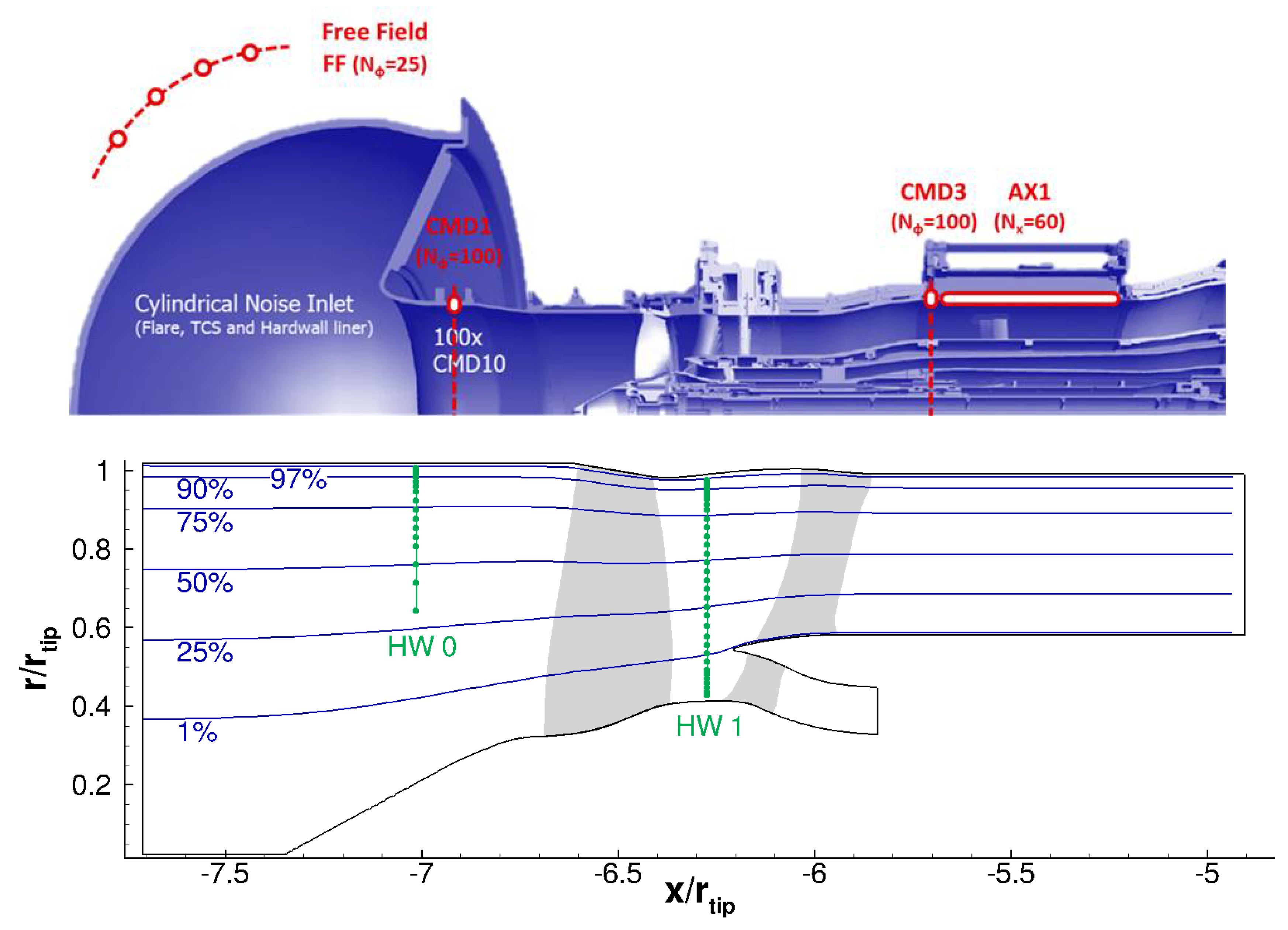
  53. Kissner, C.A.; Guérin, S.; Behn, M. Assessment of a 2D Synthetic Turbulence Method for Predicting the ACAT1 Fan’s Broadband Noise. In Proceedings of the 25th AIAA/CEAS Aeroacoustics Conference, Delft, The Netherlands, 20–23 May 2019. [Google Scholar] [CrossRef]
  54. Cader, A.; Polacsek, C.; Garrec, T.L.; Barrier, R.; Benjamin, F.; Jacob, M.C. Numerical prediction of rotor-stator interaction noise using 3D CAA with synthetic turbulence injection. In Proceedings of the 24th AIAA/CEAS Aeroacoustics Conference, Atlanta, GA, USA, 25–29 June 2018. [Google Scholar] [CrossRef]
  55. Polacsek, C.; Cader, A.; Barrier, R. Aeroacoustic design and broadband noise predictions of a turbofan stage with serrated outlet guide vanes. In Proceedings of the 26th International Congress on Sound and Vibration, Montreal, QC, Canada, 7–11 July 2019. [Google Scholar]
  56. Kissner, C.; Guérin, S. Fan Broadband Noise Prediction for the ACAT1 Fan Using a Three-Dimensional Random Particle Mesh Method. In Proceedings of the 26th AIAA/CEAS Aeroacoustics Conference, Reno, NV, USA, 15–19 June 2020. [Google Scholar]
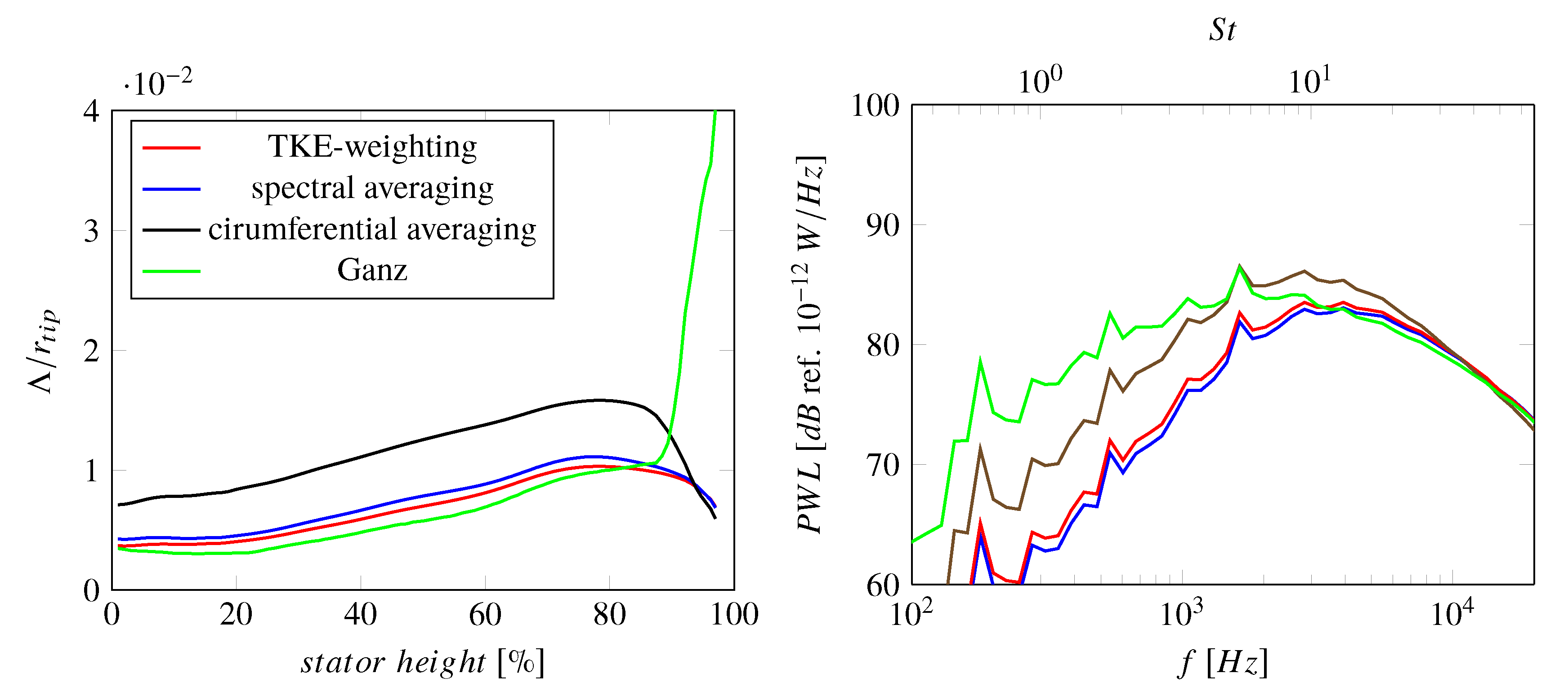
Figure 1. Sketch of the UFFA test rig at AneCom AeroTest (top): Positions of acoustic instrumentation in the free field (FF), in the inlet duct (CMD1), and in the bypass duct (CMD3 and AX1) are shown in red (TurboNoiseBB consortium, reprint with permission); Example of a Reynolds-Averaged Navier-Stokes (RANS) domain (bottom): Streamlines at relative stator heights of 1%, 25%, 50%, 75%, 90%, and 97% are shown in blue and radial measurement positions in the fan inlet section (HW 0) and in the fan interstage section (HW 1) are indicated by green markers.
Acoustics 02 00029 g001
Figure 2. Impact of choice of turbulent length scale (TLS) definition on predicted sound power levels.
Acoustics 02 00029 g002
Figure 3. Comparison of extracted turbulence characteristics at HW 1 position and extrapolated turbulence characteristics at the stator leading edge: Radial distributions of turbulent kinetic energy k and turbulent length scale Λ at HW 1 and stator leading edge positions are shown.
Acoustics 02 00029 g003
Figure 4. Impact of choice of analysis plane on predicted rotor-stator-interaction (RSI) broadband noise: Sound power level spectra downstream of the stator vanes for HW 1 and stator leading edge positions are shown.
Acoustics 02 00029 g004
Figure 5. Flow separation near rotor leading edge: Streamlines are shown in black and the contours show non-dimensional turbulent kinetic energies. The interstage slice corresponds to the HW 1 position and the black contour lines indicate the considered domain between the streamlines of 1% and 97% of the stator height.
Acoustics 02 00029 g005
Figure 6. Non-dimensional turbulent kinetic energy values measured by the hot-wire probes at position HW 1 in the interstage region.
Acoustics 02 00029 g006
Figure 7. Impact of choice of solver and mesh topology on turbulence characteristics for simulations using a Menter SST k- ω turbulence model: Radial distributions of turbulent kinetic energy k and turbulent length scale Λ are shown.
Acoustics 02 00029 g007
Figure 8. Impact of choice of solver and mesh topology on velocities at 90%, 75%, 50%, 25% (top to bottom) stator height for simulations using a Menter SST k- ω turbulence model
Acoustics 02 00029 g008
Figure 9. Impact of choice of solver and mesh topology on fluctuating velocities at 90%, 75%, 50%, 25% (top left to bottom right) for simulations using Menter SST k- ω turbulence model
Acoustics 02 00029 g009
Figure 10. Comparison of wake velocity deficits for all RANS simulations at 75% (top) and 50% (bottom) of the stator height. The dashed, black lines mark the experimental values.
Acoustics 02 00029 g010
Figure 11. Comparison of wake widths for all RANS simulations at 75% (top) and 50% (bottom) of the stator height. The dashed, black lines mark the experimental values.
Acoustics 02 00029 g011
Figure 12. Impact of choice of solver and mesh topology on predicted RSI broadband noise using a Menter Shear-Stress-Transport (SST) k- ω turbulence model: Sound power level spectra downstream are shown.
Acoustics 02 00029 g012
Figure 13. Impact of type of linear eddy viscosity turbulence model on velocities at 90%, 75%, 50%, 25% (top to bottom) stator height for simulations using a linear eddy viscosity turbulence model.
Acoustics 02 00029 g013
Figure 14. Impact of type of linear eddy viscosity turbulence model on fluctuating velocities at 90%, 75%, 50%, 25% (top left to bottom right) for simulations using a linear eddy viscosity turbulence model.
Acoustics 02 00029 g014
Figure 15. Impact of type of linear eddy viscosity turbulence model on turbulence characteristics: Radial distributions of turbulent kinetic energy k and turbulent length scale Λ are shown.
Acoustics 02 00029 g015
Figure 16. Impact of type of linear eddy viscosity turbulence model on predicted RSI broadband noise: Sound power level spectra downstream of the stator vanes are shown.
Acoustics 02 00029 g016
Figure 17. Impact of choice of a more advanced turbulence model on velocities at 90%, 75%, 50%, 25% (top to bottom) stator height.
Acoustics 02 00029 g017
Figure 18. Impact of choice of a more advanced turbulence model on fluctuating velocities at 90%, 75%, 50%, 25% (top to bottom) for simulations.
Acoustics 02 00029 g018
Figure 19. Impact of choice of a more advanced turbulence model on turbulence characteristics: Radial distributions of turbulent kinetic energy k and turbulent length scale Λ are shown.
Acoustics 02 00029 g019
Figure 20. Impact of choice of a more advanced turbulence model on predicted RSI broadband noise: Sound power level spectra downstream of the stator vanes are shown.
Acoustics 02 00029 g020
Table 1. Solvers and turbulence models.
TurbulenceTurbulence Model
RANSSolverModelExtensions
1, 2TRACE [41]Menter SST k- ω none
3, 5, 8elsA [42]Menter SST k- ω none
4, 7ANSYS CFX v19.2 / v19.1 [43]Menter SST k- ω none
6G3D::Flow [44]Menter SST k- ω none
9 M u 2 s 2 t [45,46]Menter SST k- ω Kato-Launder mod.
10TRACEMenter SST k- ω
with Vorticity Source Term
none
11TRACEMenter SST k- ω Kato-Launder mod.
modified vortex extension
(rotational fix)
12HYDRA [47]Menter SST k- ω modifications for
turbulent Mach number,
rotation, low Re etc.
13 M u 2 s 2 t Wilcox k- ω Kato-Launder mod.
14 M u 2 s 2 t Wilcox k- ω Kato-Launder mod.,
γ R e ϑ t transition model
15TRACEWilcox k- ω Schwarz limiter
16TRACEWilcox k- ω Kato-Launder mod.
17, 18elsASmith k-lnone
19TRACEHellsten EARSM k- ω none
20TRACEWilcox stress- ω none
21TRACESSG/LRR- ω none
22TRACEJH stress- ω h none
Table 2. Operating conditions used for the simulations.
BypassCoreInletInletAmbientAmbient
FanMassMassTurbulenceTurbulentPressureTemperature
RANSRPMFlow [kg/s]Flow [kg/s]Intensity [%]Length Scale [m][hPa][K]
1, 2, 4,
10, 15, 16,
19-22
3828.148.756.410.30.04995.6292.8
33828.249.026.371.06.4 × 10 6 995.6292.8
53828.248.756.410.3-995.6292.8
63828.148.766.391.00.01995.6292.8
73828.248.756.440.30.04995.3292.8
83828.348.726.430.230.01995.3292.8
93828.248.756.410.360.0431013.25288.15
113856.149.856.700.880.000181013.25288.15
123828.149.106.450.300.04995.3292.8
13, 143828.248.756.410.360.0431013.25288.15
173828.248.756.410.3-995.6292.8
183828.348.726.430.230.01995.3292.8
Table 3. Geometry and meshing.
TipTotalAzimuthal WakeBoundarySpatial
ClearanceMesh SizeResolutionLayerDiscretization
RANS[mm][Mio. cells]at R = 75% [cells]ResolutionScheme
1, 10, 12,
15, 16,
19–22
0.786.5≈30resolved2nd order
20.784.8≈20resolved2nd order
30.6363≈30resolved3rd order
40.7870>25resolvedCFX high resolution
50.784.5≈30resolved2nd order
60.7815.4≈20resolved3rd order convective,
2nd order diffusive
70.637.0≈20resolvedCFX high resolution
8, 180.6338.0≈20resolved2nd order
9, 13, 140.6335.5≈30wall functions (OGV),
resolved (rotor)
2nd order
110.58 (LE)
0.69 (TE)
11.3≈15resolved2nd order
170.784.5≈30resolved2nd order