Article

Corrosion of Aluminium and Zinc in Concrete at Simulated Conditions of the Repository of Low Active Waste in Sweden

Division of Surface and Corrosion Science, School of Engineering Sciences in Chemistry, Biotechnology and Health, KTH Royal Institute of Technology, Drottning Kristinas väg 51, SE 100-44 Stockholm, Sweden
*
Author to whom correspondence should be addressed.
Corros. Mater. Degrad. 2021, 2(2), 150-162; https://doi.org/10.3390/cmd2020009
Submission received: 12 March 2021 / Revised: 6 April 2021 / Accepted: 14 April 2021 / Published: 18 April 2021

Abstract

:
The corrosion performance of Aluminium (Al) and zinc (Zn) is of interest in repositories for radioactive waste as the production of hydrogen gas during their anoxic corrosion may create open pathways for the transport of radioactive ions. Al and Zn rods were embedded in concrete cylinders and immersed in artificial groundwater at anaerobic conditions for 2 weeks and up to 2 years in laboratory conditions. Corrosion rates were determined to enable predictions and estimations of risks for gas evolution and the assessment of the potential impact of corrosion on the structural integrity of concrete in the final repository of low and intermediate level metal-containing waste from dismantled nuclear power plants. Samples were collected after 2, 4, 12, 26, 52 and 104 weeks. The observed corrosion rates were higher for Al compared with Zn, as expected, but both materials revealed comparatively high initial corrosion rates that decreased with time, reaching steady state after 26–52 weeks. Some of the Al containing concrete cylinders were cracked as a result of the corrosion processes after 2 years of exposure, thereby providing free passage between the embedded metal and the surrounding environment. No such effects were observed for Zn. Comparative studies were performed on non-concrete-embedded Al and Zn immersed in artificial groundwater. Observed long-term corrosion rates (1–2 years) were similar to corresponding corrosion rates in concrete. The results indicate that immersion studies in artificial groundwater can be used to estimate the long-term corrosion performance of Zn and Al in concrete.

1. Introduction

Dismantling of nuclear power plants will result in a large volume of low and intermediate active waste that needs to be stored safely in a final repository. In Sweden, such materials are not recycled as there is a risk of introducing radioactive material into circulation in society. The material is instead encapsulated in concrete and kept in specially built vaults in the bedrock approximately 60 m below the Baltic seabed [1]. Concrete is used to contain the potentially active waste and hinder and delay radioactive species being environmentally released and is intended to last for at least 10,000 years. The long service life requested does of course put high demands on the concrete and its properties to withstand both natural degradation but also the influence of the materials stored within. Cracking of the concrete caused by hydrogen evolution from corroding metals like aluminium (Al) and zinc (Zn) at anaerobic conditions would open pathways for radioactive metal ions and particles to be transported from the repository into e.g., the groundwater. Since Al and Zn are commonly used metal components of both indoor and outdoor constructions, it is important to investigate their corrosion performance if encapsulated in concrete at relevant repository conditions, i.e., at anaerobic conditions and in contact with ground water.
Corrosion of metals in concrete is a well-known and thoroughly researched phenomenon, particularly in relation to steel reinforcement bars used in various outdoor constructions. Several studies have investigated the influence of both atmospheric and environmental conditions on the corrosion performance of such materials [2,3,4]. Corrosion studies on steels and their performance as reinforcement materials are an obvious necessity to minimise the risk of construction failure. The choice of steel as a reinforcement material is likewise obvious as steel has suitable mechanical properties, is comparatively cheap and in general shows a very low corrosion rate at alkaline environments such as concrete in which pH typically ranges from 11–13.
Large knowledge gaps exist though in relation to corrosion of other metals such as Zn and Al in contact with concrete. The corrosion performance of Zn has to some extent been investigated, though mainly for rebars of galvanised steel showing corrosion rates of the Zn layer of 0.2–1.1 g m−2 year−1 after 10 years of exposure at marine aerobic conditions [2]. Corrosion of Al embedded in concrete is less investigated. Due to the amphoteric nature of Al, it is well known that Al is very susceptible to corrosion at alkaline aqueous conditions for which its mechanisms have been evaluated [5,6,7,8,9]. Some studies report on the corrosion behaviour on Al in concrete and concrete-related environments [3,10,11,12,13]. Few studies have assessed corrosion rates, though corrosion rates between 22 and 670 g m−2 year−1 have been reported in alkaline aqueous solutions of pH 10–11 at temperatures of 20, 30 and 60 °C for up to 80 days [6]. The same study report decreasing corrosion rates with time and attributed this behaviour to the formation of corrosion products on the surface. However, at pH 12, the formation of corrosion products was believed to be insufficient to form a protective surface barrier. The authors have not been able to identify any studies that investigates the corrosion performance of either Zn or Al embedded in concrete at anaerobic conditions in ground water from either a kinetic or corrosion product evolution perspective.
Since the planned service life of the concrete used in the Swedish repository is at least 1000-times longer than the longest time frame investigated in the reported study above and that no data exists for anaerobic conditions, it is crucial to investigate potential adverse effects that corrosion of embedded Al and Zn at anaerobic exposure conditions may have on its structural integrity. From a risk assessment perspective, it is furthermore important to evaluate if gas evolution and formation of voluminous corrosion products may lead to cracking of the concrete as this in turn may result in leaching of radioactive metal species into the groundwater adjacent the repository setting. The possibility to translate corrosion performance findings generated in alkaline aqueous solutions at anaerobic conditions to the corrosion behaviour in concrete would facilitate testing of other metals and metal combinations.
The main aim of this study was hence to determine corrosion rates for up to 2 years for Al and Zn embedded in concrete when immersed in synthetic groundwater at anaerobic conditions mimicking the repository conditions of Sweden. The study included the identification of corrosion products as well as visual inspections of the formation of voids and cracks within the concrete. Generated data enables long-term predictions on the concrete integrity and calculations of the amount of hydrogen gas (not included in this study) that may be produced within the repository. Such results can in turn be used for further evaluation of the potential impact that corroding metals may have on the structural integrity of the concrete during final repository of low and intermediate active metal-containing waste. Changes in structure and chemistry of the concrete were not investigated within this study.

2. Materials and Methods

Rods of aluminium (99.0 wt.% Al) and zinc (99.9 wt.% Zn) (Φ 10 mm, Goodfellow) were cut into 30-mm long pieces. Rods were used to minimise the influence of edges and also to facilitate the symmetry of the concrete cylinders to have an equal thickness of concrete all around the samples. The cut surfaces were wet ground using 1200 SiC paper to ensure reproducible surfaces. The remainder of the cylindrical sample surfaces were left as-received to represent aged surfaces more relevant for real exposure scenarios. After abrasion, the samples were ultrasonically cleaned in acetone and isopropanol for 5 min, respectively, and dried with cold dry nitrogen gas. The samples were kept in a desiccator for 24 h before exposure.
To achieve an accelerated exposure up to 2 years (the final repository is supposed to maintain integrity for at least 10,000 years), the concrete had a high water–cement ratio (w/c) of 0.55 to obtain a comparatively porous matrix able to facilitate faster water, gas and ion transport. The concrete composition, bearing capacity, and extent of separation were optimised in collaboration with experts at RISE, Sweden, in order to ensure that the embedded metal cylinders did not sink within the concrete during curing and that the composition would be fairly representative for repository conditions. The final concrete composition included 1150 g Portland cement type CEM I (Degerhamn anläggningscement™), 230 g ultrafine calcium carbonate (Omyacarb® 2GU, Gummern, Austria), 2300 g standard sand (CEN-Normensand according to EN 196-1) [14] and 600 g ultra-pure water (Millipore 18.2 MΩcm). The workability of the concrete was measured by the concrete slump test and the flow spread of different concrete batches was 135 ± 5 mm.
Al and Zn samples were embedded in individual concrete cylinders with a height of 80 ± 10 mm and a diameter of 63 ± 0.1 mm. Concrete was poured into cylindrical moulds made of PVC to a height of 40 mm. The metal samples were inserted approximately 15 mm into the concrete layer in the middle of the cylinder. A second layer of concrete was poured and the two layers were stitched together using a thin plastic rod to ensure a solid coherent cylinder, Figure 1. After stitching, a third layer was poured and stitched accordingly. The cylinders were covered with a plastic sheet to prevent evaporation and left to cure for 20 h.
The cured concrete cylinders were removed from the PVC moulds and inserted in 1-L HDPE (high-density polyethylene) vessels filled with 730 ± 10 mL artificial groundwater (AGW) to simulate conditions in the SFR (short-lived radioactive waste repository). The composition of the artificial groundwater was based on information provided from SKB, the Swedish Nuclear Fuel and Waste Management Company (DokumentID 1221857, Version 2.0) [15], Table 1. All salts used were of analytical grade and ultra-pure water (MilliQ 18.2 MΩcm) was used as solvent.
The AGW filled vessels were positioned in a glove box (MBRAUN UNIlab) with an argon atmosphere (<0.1 ppm H2O/O2). Triplicate samples for corrosion rate measurements and duplicate samples for corrosion product identification for each time period were kept in the glovebox for 2, 4, 12, 24, 52 and 104 weeks, respectively. The concrete cylinders in plastic containers without AGW were placed in the glovebox and exposed in parallel for reference. After exposure the concrete cylinders were removed and cracked within 1 h using a hydraulic press at RISE. Metal samples still firmly attached to the concrete were carefully removed using a chisel on the concrete surrounding the sample without damaging the sample surfaces. The pH of the AGW after immersion of concrete cylinders had increased from 8.1 ± 0.2 to 12 ± 0.5.
Al and Zn samples, abraded and cleaned as described above, were placed in 25-mL HDPE containers filled with 20 mL AGW. As the pH of the AGW was impossible to adjust to 12 without significantly changing the ionic strength, it was adjusted to 12.5 ± 0.2 by immersing a concrete cylinder without a metal sample until a stable pH was established. The containers were placed in a sealed desiccator that was purged with cold nitrogen gas. The samples were exposed for the same time periods as the concrete-embedded samples to facilitate comparison of corrosion rates in concrete and in AGW. The desiccator was purged every couple of months and after each sample removal to preserve the inert atmosphere.
Morphology and rudimental chemical analytical information were achieved using scanning electron microscopy combined with elemental analysis (SEM/EDS) using a PHILIPS FEI XL30 instrument (PHILIPS) with an Oxford X-Max 20 mm2 SDD EDS detector (Oxford Instruments) and Inca software (version 5.04). Identification of crystalline phases was performed with a Kratos X’pert Pro Panalytical X-ray diffraction system (CuKα radiation, λ = 1.5405981 Å, (Kratos) and a 0.27° parallel plate collimator. Grazing incidence data was generated using at an angle of 1.5°, corresponding to an approximate surface penetration depth of 2.7–4.9 μm. IR spectra were obtained using a Bruker Lumos II IR microscope (Bruker).
Corrosion products were removed (chemically pickled) from the Al samples following the procedure developed and described in [16]. Zn corrosion products were removed using ammonium acetate according to the ASTM G1-03 (2011) standard [17]. Complete corrosion product removal was confirmed by means of SEM and corrosion rates were determined following the procedure of plotting mass loss according to ISO 8407-2009 [18]. The corrosion rates are presented as average rates, assuming a constant corrosion rate extrapolated to one year.

3. Results and Discussion

Three main research issues were addressed to enable the evaluation of risks of concrete cracking induced by corrosion of concrete-embedded Al- and Zn-containing metallic objects. Each issue is discussed in the following based on generated research findings.

3.1. Is There a Risk of Corrosion-Induced Cracking of Concrete Saturated with Oxygen-Free Groundwater and Exposed at Oxygen Free Conditions Simulating the Final Repository of Low and Intermediate Waste Including Aluminium—And Zinc Objects from Nuclear Facilities?

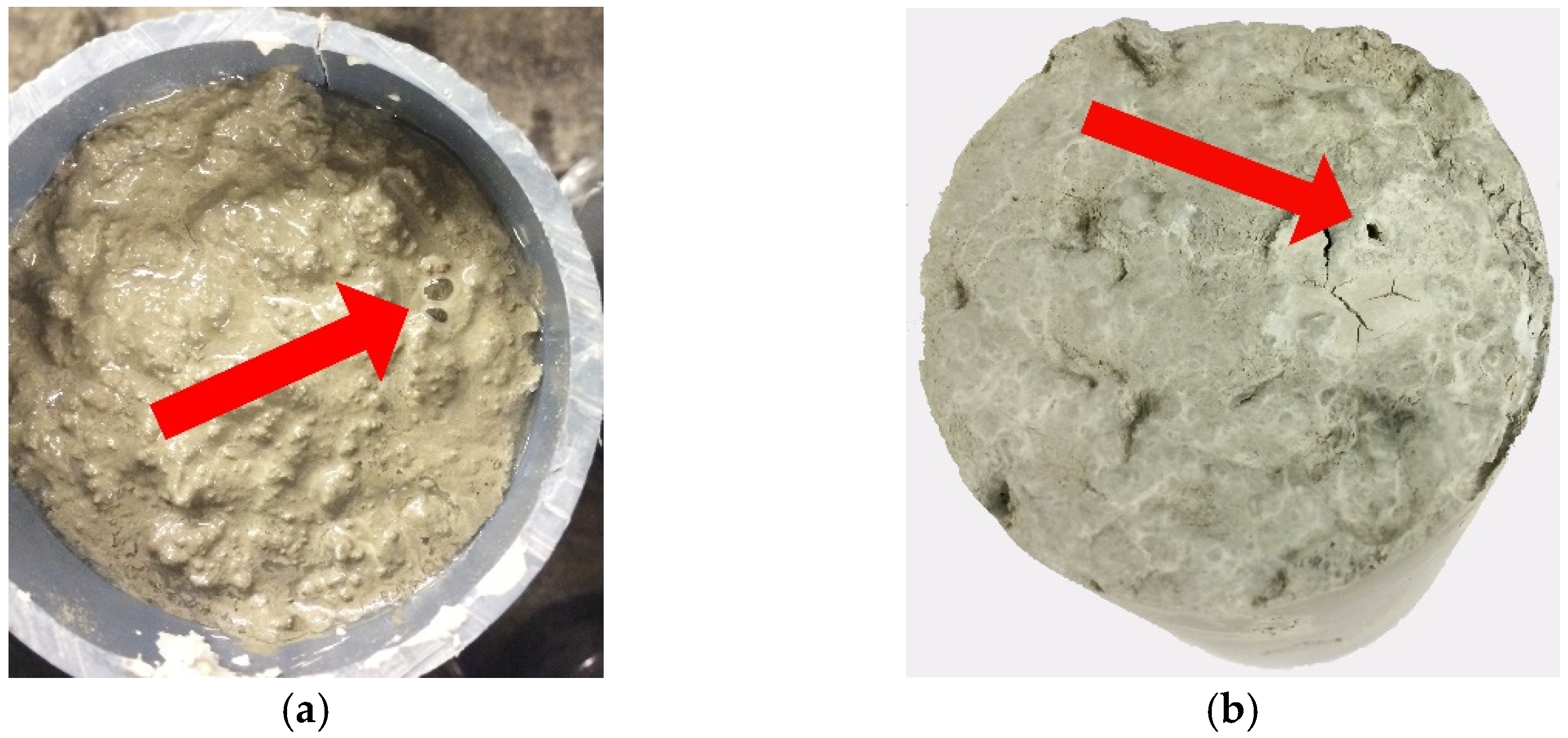
Bubbles were observed on the surface of the Al containing concrete cylinders within minutes after casting the last layer of concrete, Figure 2a. The effect was also evident after curing for 20 h, Figure 2b.
All concrete cylinders were, after removal from the AGW, visually inspected for the presence of cracks which are indicative of internal stresses caused by gas evolution from the corrosion process or by expanding volumes of evolved corrosion products. Independent on the material embedded inside the concrete, no cracks were observed in any of the cylinders exposed for either 2, 4, 12, 24 or 52 weeks, as seen in Figure 3a. However, two of the five cylinders with embedded Al revealed after 104 weeks of exposure evident cracks originating from the embedded Al sample surfaces all the way to the outside of the cement cylinder, Figure 3b. The width of the cracks, up to 3 mm, indicates that the underlying mechanism is internal pressure caused by gas evolution from the corrosion process and/or expanding corrosion product volumes as naturally formed cracks due to shrinkage or expansion during curing of the concrete would be hairline thick [19]. It is also unlikely that the concrete cylinders would crack from the shrinking process during drying as the cylinders were kept moist during the first 24 h of settling and curing before immediately immersed in AGW. One gas vent leading from the embedded Al samples to the top of the concrete surface was observed for each of the Al-containing cylinders. These vents, marked by the red arrow in Figure 2b, were formed during the curing step. Their presence, which allows the removal of gas formed during the corrosion process, indicates that gas pressure did not have any significant impact on the cracking of the concrete. Rather, these failures were effects of the expanding volume of formed corrosion products. No cracking of the Zn containing cylinders was observed during exposure in AGW and no gas vents were observed either during casting, curing or exposure.
When dismounting the metal samples from the concrete cylinders after the different exposure periods, a majority of the Al-containing cylinders cracked into multiple pieces revealing voids of varying size directly above the exposed metal sample, Figure 4a. These voids had formed by the evolution of hydrogen gas as the Al samples immediately started to corrode in contact with the strongly alkaline (pH 12.5) concrete environment. The rapid initial corrosion also resulted in a large amount of corrosion products causing poor adhesion between the Al samples and the concrete. Consequently, the Al samples were very easy to remove after exposure from the concrete as they essentially were loose and spontaneously detached. Cracking of the cement cylinders also revealed cross sections of the gas vents as the cylinders tended to crack along the vents where the mechanical strength of the concrete was diminished. It was clear that the vents reached all the way through the concrete from the Al sample inside the cylinder to the upper outer surface, as seen in Figure 4b.
The Zn containing concrete cylinders generally broke into two halves when cracked indicating a higher structural integrity of the concrete compared with the Al containing cylinders. Most cylinders contained small voids in connection with the samples. This indicates that some gas evolution occurred initially but was not sufficient to create gas vents to the surface of the concrete, as seen in Figure 5a,b, as no gas vents to the surface were observed. The majority of the exposed Zn samples was firmly attached to the concrete without any significant visually observed formation of corrosion products. The samples had to be carefully chiselled out as not to damage their surfaces.
In all, corrosion of both Al and Zn embedded in concrete will cause gas evolution powerful enough to create voids in the concrete. This effect was more severe for Al as vents formed already during the curing which enabled the gas to exit from the concrete cylinder. These vents can act as routes for transportation of both corrosive species into the concrete cylinder and also allow for transport of potentially radioactive species from the intended containment. The structural integrity of all concrete cylinders containing Zn was intact even after 2 years of exposure in oxygen free AGW and no cracks were visually observed. The integrity of the Al containing concrete cylinders was intact for the first 2–52 weeks of exposure. However, after 2 years (104 weeks) 40% of the concrete cylinders suffered from substantial cracking that could only have been caused by the internal influence from the corrosion process of Al.

3.2. How Fast Will Aluminium and Zinc Objects from Dismantled Nuclear Power Plants Corrode with Time at Anaerobic Conditions When Embedded in Concrete Saturated with Oxygen-Free Groundwater and What Corrosion Products Are Formed?

It is well known that Al rapidly corrodes at pH values exceeding 9 [7]. Reported corrosion rates in alkaline aqueous solutions ranges between 22 and 670 g m−2 year−1 (8.1–248 µm year−1) [6]. As a result, high corrosion rates of Al were expected when exposed in concrete (pH 12.5 ± 0.2). Corrosion rates of 20 µm year−1 have been reported for Zn–Al alloys (12 wt.% Al) exposed at aerobic conditions in concrete [2]. These rates were by far exceeded by the rates measured in concrete in this study (Figure 6 and Table 2). The initial corrosion rate was equal to 2700 g m−2 year−1 after 2 weeks (based on triplicate samples), as seen in Figure 6a, assuming a constant corrosion rate extrapolated to 1 year. The variation in corrosion rates between the triplicate samples was large for the two initial exposure time periods, 2 and 4 weeks, and no significant reduction in corrosion rates was observed until after 12 weeks. After 26 weeks, the corrosion rate was substantially reduced and the variation between the triplicate samples was significantly smaller, 443 g m−2 year−1. A reduction in corrosion rate was expected due to the gradual formation of corrosion products formed on the Al surfaces able to act as a physical barrier slowing down the passage of ions and corrosive species. Interestingly enough, the Al samples exposed within the cracked concrete cylinders exposed for 2 years did not show any different corrosion rates compared with uncracked cylinders (all in the range 309 ± 20 g m−2 year−1). As the test was terminated after this exposure time, and no inspection of the cylinders was performed in-between 1 and 2 years of exposure, the exact time for the fracture is unknown. How long the crack in the concrete had been open for transport of AGW into the embedded poorly adherent Al samples is, hence, unknown. It could be that it fractured shortly before the test was terminated and that an increased transport of AGW into the Al surface was not sufficient to influence the corrosion rate. It could also be that the barrier properties of the corrosion products were sufficient to slow down any effect of corrosive species. It should, thus, be kept in mind that cracking of the cylinders may have an influence on the corrosion rates. However, measured corrosion rates are of the same order of magnitude indicating minor implications of such a scenario.
Zn generally shows lower documented corrosion rates at alkaline conditions compared with Al and can according to simplified systems [2,20] be expected to be in a passive state at pH 12 ± 0.5. However, high initial corrosion rates were determined after 2 weeks (360 g m−2 year−1) (Figure 6b and Table 2), but decreased rapidly to substantially lower rates after 26 weeks (17 g m−2 year−1) and 104 weeks (6 g m−2 year−1). Corrosion rates of 0.2–1.1 µm year-1 have been reported in previous studies of galvanised rebars exposed in concrete for 10 years in marine environments [2], and correlate well with the results obtained in this study. The variation between the triplicate samples exposed for 2 weeks was comparatively large. This is most probably a result of surface reactivity variations between the unexposed freshly abraded sample surfaces that decreased with time as stable corrosion products formed on the surface creating a uniform physical barrier slowing down the corrosion process. Observed differences in initial corrosion rates, for both Al and Zn, are also a consequence of the porosity of the AGW saturated concrete adjacent to the embedded metal forming local corrosion cells, which influence the electrochemical dissolution process [21]. After 12 weeks of exposure in concrete there were only small variations (13%) between triplicate samples, and even smaller for the samples exposed for 26, 52 and 104 weeks (≈2%). The observation of uniformly corroded samples without any observation of locally corroded areas supports the conclusion that the initial large variation between triplicate samples predominantly was caused by variations in surface characteristics of the freshly prepared unexposed surfaces.
The morphology of the corrosion products on the concrete-embedded Al and Zn surfaces after 1 year of exposure is illustrated in Figure 7. Elemental analysis by means of EDS revealed the predominance of Al and O for the Al sample, and of Zn and O for the Zn sample. Both metals revealed the presence of C and Ca. These results are in accordance with findings with XRD that resulted in diffractograms that revealed significant peak overlap, especially for Zn, which complicated a detailed identification of corrosion products, Figure 7.
Al(OH)3 was the predominant corrosion product on the Al samples. No crystalline phases that directly could be related to the concrete constituents were observed. This was most probably a result of the rapid corrosion process and gas evolution taking place when the Al samples were inserted into the wet concrete. The gas created a narrow space between the concrete and the Al samples preventing incorporation of concrete into the corrosion products. The formation of thick corrosion products and continued evolution of gas further caused porous and partially non-adherent corrosion products that were left at the concrete interface when cracked open. FTIR analysis performed after the shorter exposure periods supported the findings of Al(OH)3 and implied the presence of both amorphous Al2O3 and CaCO3 (Figure 8a).
Since the investigations were performed on samples after exposure without any treatment or attempt to remove any residues from the concrete on the surface, concrete was still present on the surfaces of the samples. The incorporation of concrete constituents into the corrosion products on the Zn samples was therefore impossible to avoid without risking removing, changing or destroying the corrosion products. Both XRD and FTIR findings revealed spectra with overlapping peaks, which hampered their interpretation. The incorporation of concrete constituents into the corrosion products was evident. XRD revealed the presence of two crystalline compounds that could be related to the corrosion process, i.e., Zn(OH)2 and Ca(Zn(OH)3)2·2H2O. The FTIR results (Figure 8b) supported the presence of both Zn(OH)2 as well as CaCO3 and indicated the presence of amorphous Zn5(CO3)2(OH)6.
In all, the initial corrosion rates determined for Al embedded in concrete at the anaerobic AGW conditions were significantly higher compared with reported corrosion rates for Al exposed in alkaline aerated aqueous solutions, but decreased with time to similar levels. No significant differences in corrosion rates were observed for the embedded Al samples exposed in the intact and cracked concrete cylinders. This implies that the corrosion rate limiting step is controlled by the barrier properties of the corrosion products formed on the Al surface and not by the transport/diffusion of corrosive species through the concrete.
The embedded Zn samples in concrete displayed similar corrosion rates as rates of galvanised reinforcement bars reported in the literature.
Hydroxides and to some extent carbonates were the main corrosion products found on both Al and Zn after exposure in concrete.

3.3. Given the Case That Concrete Cracking Occurs in the Repository for Short Lived Radioactive Waste—How Fast Will Al- and Zn-Based Objects Corrode in Oxygen-Free Artificial Ground Water?

With the fracturing of the concrete cylinders and the subsequent possibility of free transport of AGW, ions and corrosive species to and from the embedded metal surfaces, it was considered important to investigate differences between the corrosion of the Al and Zn metals in concrete and in AGW only. As discussed in the previous section, no significant difference in corrosion rates between the intact and cracked cylinders could be distinguished after 2 years of exposure of the Al samples. In addition, it was not possible to determine when the cylinders cracked and for how long the cracks allowed for free transport of AGW into the metal surfaces. However, these results suggest that the corrosion rate determining step was the barrier effect of formed corrosion products rather than direct surface contact with AGW. This hypothesis was supported by the corrosion rates determined for Al exposed in AGW only (Figure 9a and Table 3).
The initial corrosion rates of the Al samples in AGW were after 2 weeks (8326 g m−2 year−1) and 4 weeks (3856 g m−2 year−1), substantially higher (≈68 and 47%, respectively) compared with corresponding rates when exposed embedded in concrete, Figure 5a,b and Table 3. However, after 12 weeks of exposure, the corrosion rates were very similar and remained almost the same as in concrete after 24, 52 and 104 weeks of exposure (146 g m−2 year−1 after 2 years) (Figure 5a and Figure 9a and Table 2 and Table 3). The similarity between the two different exposure conditions (concrete immersed in AGW and AGW only) strongly implies that the formation and barrier properties of corrosion products formed on the surface of the Al samples govern the rate limiting steps. It can also be concluded that exposures in AGW could, at least for the longer exposure times, be used to predict corrosion rates of Al in concrete at given conditions, and that cracks forming in the concrete should not speed up the corrosion process.
Albeit, the concrete cylinders containing the Zn samples did not crack during the 2-year exposure, investigations of the corrosion behaviour of Zn in AGW only is of importance. If the corrosion rates are comparable, testing in AGW is a simpler procedure in order to evaluate long-term corrosion rates compared with testing of embedded samples in concrete. Zn corroded at a rate of 172 g m−2 y−1 after 2 weeks (Figure 9b and Table 3), that is about half the corrosion rate determined when embedded in concrete, Figure 5b and Table 2. However, after longer exposure time periods the corrosion rates were similar. This suggests that the testing in AGW for the given exposure conditions can be used to predict corrosion rates of Zn embedded in concrete. The variation between the triplicate samples was initially (after 2 weeks) very small (Figure 9b and Table 3). Larger variations (41–84%) were observed after 12, 52 and 104 weeks. Observed differences in corrosion rates between the exposures in concrete and in AGW may be caused by deficiencies in the experimental set up for the AGW investigation. Exposures in the latter tests were made with the cylindrical samples lying down in the test vessel, a condition that created a rather large contact area between the Zn sample and the test vessel and hence suitable conditions for crevice corrosion. It would have been desirable to use of a different vessel that ensured a small contact area between the sample and the vessel. However, in order to achieve identical exposure conditions for Al and Zn it was necessary to use vessels capable of withstanding the high pressure that was induced by the initially extensive gas evolution taking place during the corrosion of Al. Several types of vessels were tested and only one met the requirements as most vessels were not gas tight and allowed for spontaneous removal of the AGW as it was pushed out of the vessels by the over-pressure created by the gas formed by the corrosion process. The disadvantage of the selected vessels was that they required the cylindrical samples to lie down at the bottom of the vessel. However, this parameter was considered less critical than the removal of the AGW from the vessels.
The Zn samples exposed in AGW were initially (2–4 weeks) visually very similarly corroded to the samples exposed in concrete with no signs of localised corrosion. For the longer exposure times, the area of the Zn samples in contact with the bottom of the vessel was partly covered by white corrosion products (Figure 10a). After the pickling procedure it was evident that local corrosion processes had been progressing in these areas (Figure 10b). These results explain the slightly higher corrosion rates in AGW compared with concrete. The surfaces only in contact with AGW did not show any signs of localised corrosion.
As the entire surfaces of the Al samples were heavily corroded and covered with thick corrosion products no specific areas could be connected with localised corrosion or be determined to have been in contact with the bottom of the vessel.
No identification of the corrosion products formed on any of the samples exposed in AGW was conducted within the framework of this study. The composition is though anticipated to be the same, or at least similar, as observed when the metals were exposed in concrete.
In all, Al and Zn displayed similar corrosion rates when exposed in AGW compared to when embedded in concrete, immersed in AGW at deaerated conditions. This suggests that crack formation of concrete, that potentially can take place during final repository conditions, is not expected to speed up the corrosion process. The results elucidate further that long-term corrosion rates of Zn and Al embedded in concrete can be estimated from exposures in AGW only.

4. Summary

The repository for short-lived radioactive waste, SFR, from nuclear power plants is required to last for at least 10,000 years. In Sweden, the waste is embedded in concrete to create a barrier preventing environmental dispersion of potentially harmful species. Such dispersion may be enabled if the structural integrity of the concrete is compromised. Corrosion of Al and Zn embedded in concrete cylinders immersed in oxygen free artificial groundwater (AGW) was therefore investigated up to 104 weeks (2 years) to determine corrosion rates and evaluate the risk for gas evolution as the formation of expanding gas within the concrete during storage in the repository may cause severe cracking of the concrete. It was discovered that gas vents leading from the embedded Al samples to the surface of the concrete cylinders were already formed during curing of the concrete, conditions that enabled the possibility for transport of species to and from the metallic surfaces. Two out of five Al containing concrete cylinders were completely cracked after 2 years of exposure compromising the structural integrity. The Zn containing concrete cylinders did not show any signs of lost integrity, either during curing or as a result of the exposure conditions.
Corrosion rates of both Al and Zn in concrete were initially higher but decreased with time and reached near steady state rates after approximately 26 weeks. Determined corrosion rates of Al in cracked concrete cylinders did not show any significant difference compared with non-cracked cylinders. This suggests the barrier properties of corrosion products formed on the Al surface to be the rate limiting mechanism rather than transport of corrosive species through the concrete barrier. This hypothesis was supported by results from Al and Zn directly exposed in AGW under oxygen free conditions for which the corrosion rates were of the same magnitude after 26 weeks as the rates obtained during exposure in concrete. Similar corrosion rates were obtained after 104 weeks (2 years). The results elucidate that exposures in AGW hence can be used to predict long-term corrosion rates of Al and Zn exposed in concrete at the given exposure conditions.
Even though the corrosion rates of Al did not increase as a result of cracking of the concrete, the effects of cracking on the corrosion processes and other effects induced by the loss of structural integrity and barrier properties during the final repository should be investigated.

Author Contributions

Conceptualization, G.H. and I.O.; methodology, G.H and I.O.; validation, G.H. and I.O.; formal analysis, G.H.; investigation, G.H.; resources, G.H.; data curation, G.H.; writing—original draft preparation, G.H.; writing—review and editing, G.H. and I.O.; visualization, G.H.; supervision, G.H. and I.O.; project administration, G.H and I.O.; funding acquisition, G.H. and I.O. Both authors have read and agreed to the published version of the manuscript.

Funding

Faculty funding and financial support from SKB (Swedish Nuclear Fuel and Waste Management Co.).

Institutional Review Board Statement

Not applicable.

Informed Consent Statement

Not applicable.

Data Availability Statement

All data is included in this paper.

Acknowledgments

M-E Karlsson at KTH is highly appreciated for help with the experimental work and method development. Alexander Eriksson-Brandels, Patrik Rogers and Mariusz Kalinowski at RISE, Stockholm are greatly acknowledged for help and support with concrete development, mixing and cracking. Susanna Wold, for valuable discussions, and Annika Maier, KTH, for support and supervision of the glovebox exposure, are highly appreciated.

Conflicts of Interest

The authors declare no conflict of interest. The funders had no role in the design of the study; in the collection, analyses, or interpretation of data; in the writing of the manuscript, or in the decision to publish the results.

References

  1. Safety Analysis for SFR Long-Term Safety; Main Report for the Safety Assessment SR-PSU; TR-14-01; Svensk Kärnbränslehantering AB: Stockholm, Sweden, 2015.
  2. Zhang, X.G. Corrosion and Electrochemistry of Zinc, 11th ed.; Plenum Press: New York, NY, USA, 1996. [Google Scholar]
  3. Hansson, C.M.; Poursaee, A.; Jaffer, S.J. Corrosion of Reinforcing Bars in Concrete. R&D Ser. 2007, 3013. Available online: https://ceramrtr.ceramika.agh.edu.pl/~szyszkin/eis/Corrosion%20Of%20Reinforcing%20Bars%20In%20Concrete.pdf (accessed on 15 April 2021).
  4. Rodrigues, R.; Gaboreau, S.; Gance, J.; Ignatiadis, I.; Betelu, S. Reinforced concrete structures: A review of corrosion mechanisms and advances in electrical methods for corrosion monitoring. Constr. Build. Mater. 2021, 269, 121240. [Google Scholar] [CrossRef]
  5. Pyun, S.-I.; Moon, S.-M. Corrosion mechanism of pure aluminium in aqueous alkaline solution. J. Solid State Electrochem. 2000, 4, 267–272. [Google Scholar] [CrossRef]
  6. Tabrizi, M.R.; Lyon, S.B.; Thompson, G.E.; Ferguson, J.M. The long-term corrosion of aluminium in alkaline media. Corros. Sci. 1991, 32, 733–742. [Google Scholar] [CrossRef]
  7. Zhang, J.; Klasky, M.; Letellier, B.C. The aluminum chemistry and corrosion in alkaline solutions. J. Nuclear Mater. 2009, 384, 175–189. [Google Scholar] [CrossRef]
  8. Armstrong, R.D.; Braham, V.J. The mechanism of aluminium corrosion in alkaline solutions. Corros. Sci. 1996, 38, 1463–1471. [Google Scholar] [CrossRef]
  9. Chen, D.; Howe, K.J.; Dallman, J.; Letellier, B.C. Corrosion of aluminium in the aqueous chemical environment of a loss-of-coolant accident at a nuclear power plant. Corros. Sci. 2008, 50, 1046–1057. [Google Scholar] [CrossRef]
  10. Wang, D.; Wu, M.; Ming, J.; Shi, J. Inhibitive effect of sodium molybdate on corrosion behaviour of AA6061 aluminium alloy in simulated concrete pore solutions. Constr. Build. Mater. 2021, 270, 121463. [Google Scholar] [CrossRef]
  11. Kinoshita, H.; Swift, P.; Utton, C.; Carro-Mateo, B.; Marchand, G.; Collier, N.; Milestone, N. Corrosion of aluminium metal in OPC- and CAC-based cement matrices. Cem. Concr. Res. 2013, 50, 11–18. [Google Scholar] [CrossRef] [Green Version]
  12. Jana, D.; Tepke, D.G. Corrosion of Aluminium Metal in Concrete—A Case Study. In Proceedings of the 32nd International Conference on Cement Microscopy 2010, New Orleans, LA, USA, 28–31 March 2010; pp. 33–65. [Google Scholar]
  13. Pitts, J.W. Final Report on Corrosion of Aluminum Embedded in Concrete; 9521; U.S. Department of Commerce, National Bureau of Standards: Boulder, CO, USA; Springfield, IL, USA, 1967.
  14. Methods of Testing Cement-Part 1: Determination of Strength, EN 196-1:2016; European Committee for Standardization: Brussels, Belgium, 2016.
  15. Berg, P. F-PSAR SFR Första Preliminär Säkerhetsredovisning för ett Utbyggt SFR; Svensk Kärnbränslehantering AB: Stockholm, Sweden, 2014. [Google Scholar]
  16. Herting, G.; Karlsson, M.-E.; Odnevall Wallinder, I. A novel method to assess mass loss of aluminium in concrete. Mater. Corros. 2018, 69, 1811–1814. [Google Scholar] [CrossRef] [Green Version]
  17. Standard Practice for Preparing, Cleaning, and Evaluating Corrosion Test Specimens; ASTM-G1-03(2011); ASTM International: West Conshohocken, PA, USA, 2011.
  18. Corrosion of Metals and Alloys—Removal of Corrosion Products from Corrosion Test Specimens; ISO-8407(2009); ISO: Geneva, Switzerland, 2009.
  19. Safiuddin, M.; Kaish, A.; Woon, C.-O.; Raman, S. Early-Age Cracking in Concrete: Causes, Consequences, Remedial Measures, and Recommendations. Appl. Sci. 2018, 8, 1730. [Google Scholar] [CrossRef] [Green Version]
  20. Wranglen, G. An Introduction to Corrosion and Protection of Metals; London Chapman and Hall: London, UK, 1985. [Google Scholar]
  21. Stefanoni, M.; Angst, U.M.; Elsener, B. Kinetics of electrochemical dissolution of metals in porous media. Nat. Mater. 2019, 18, 942–947. [Google Scholar] [CrossRef] [PubMed] [Green Version]
Figure 1. Schematic of the concrete cylinder casting procedure.
Cmd 02 00009 g001
Figure 2. (a) Gas bubbles on the surface of wet concrete containing Al samples minutes after finished pouring the concrete into moulds; (b) Gas vent outlet on the upper surface of concrete cured for 20 h.
Cmd 02 00009 g002
Figure 3. (a) Concrete cylinder representative for all samples and time periods except two Al containing cylinders (out of five) exposed for two years and (b) Concrete cylinder containing Al that cracked after two years of exposure.
Cmd 02 00009 g003
Figure 4. (a) Voids formed at the top end of the Al sample embedded in concrete and (b) Gas vent leading from the top of the void to the outer upper surface of the concrete cylinder.
Cmd 02 00009 g004
Figure 5. (a) Small voids formed at the top end of some of the embedded Zn samples and (b) Some voids penetrated deeper into the concrete without puncturing the outer concrete cylinder surface.
Cmd 02 00009 g005
Figure 6. Corrosion rates of Al (a) and Zn (b) embedded in concrete immersed in artificial ground water (AGW) at anaerobic conditions for 2, 4, 12, 24, 52 and 104 weeks.
Cmd 02 00009 g006
Figure 7. Corrosion product morphology by means of XRD diffractograms and SEM images for Al (top) and Zn (bottom) embedded in concrete immersed in AGW at anaerobic conditions for 1 year.
Cmd 02 00009 g007
Figure 8. FTIR spectra generated for (a) Al and (b) Zn embedded in concrete immersed in AGW at anaerobic conditions for 2, 4, 12 and 26 weeks.
Cmd 02 00009 g008
Figure 9. Corrosion rates of Al (a) and Zn (b) exposed in artificial ground water (AGW) at anaerobic conditions for 2, 4, 12, 24, 52 and 104 weeks.
Cmd 02 00009 g009
Figure 10. Zn sample exposed in oxygen free AGW for 12 weeks (a) before and (b) after pickling.
Cmd 02 00009 g010
Table 1. Composition of artificial groundwater [g/L].
KClCaCl2Na2SO4MgCl2NaClNaHCO3FeSO4·7H2OpH
0.0421.660.570.593.680.120.0178.1 ± 0.2
Table 2. Corrosion rates of Al and Zn embedded in concrete immersed in AGW at anaerobic conditions for 2, 4, 12, 24, 52 and 104 weeks.
Exposure Time
(weeks)
Corrosion Rate
Al
(g m−2 y−1)
Corrosion Rate
Al
(µm y−1)
Corrosion Rate
Zn
(g m−2 y−1)
Corrosion Rate
Zn
(µm y−1)
22639 ± 805977 ± 298360 ± 3650 ± 5
42044 ± 899757 ± 333191 ± 1427 ± 2
121472 ± 270545 ± 10043 ± 66.0 ± 0.8
26443 ± 73164 ± 2717 ± 32.3 ± 0.4
52189 ± 2970 ± 118.3 ± 21.2 ± 0.2
104309 ± 20114 ± 76.1 ± 0.10.9 ± 0.02
Table 3. Corrosion rates of Al and Zn immersed in oxygen free artificial groundwater for 2, 4, 12, 24, 52 and 104 weeks.
Exposure Time
(weeks)
Corrosion Rate
Al
(g m−2 y−1)
Corrosion Rate
Al
(µm y−1)
Corrosion Rate
Zn
(g m−2 y−1)
Corrosion Rate
Zn
(µm y−1)
28326 ± 16813084 ± 623172 ± 1025 ± 1
43856 ± 4801428 ± 17884 ± 712 ± 1
121340 ± 36496 ± 1373 ± 3110 ± 4
26577 ± 114214 ± 4227 ± 54 ± 1
52277 ± 47103 ± 1762 ± 329 ± 5
104146 ± 4654 ± 1719 ± 163 ± 2
Publisher’s Note: MDPI stays neutral with regard to jurisdictional claims in published maps and institutional affiliations.

