Article

Influence of Mg2+ Ions on the Formation of Green Rust Compounds in Simulated Marine Environments

Laboratoire des Sciences de l’Ingénieur pour l’Environnement (LaSIE), UMR 7356 CNRS-La Rochelle Université, Av. Michel Crépeau, CEDEX 01, F-17042 La Rochelle, France
*
Author to whom correspondence should be addressed.
Corros. Mater. Degrad. 2021, 2(1), 46-60; https://doi.org/10.3390/cmd2010003
Submission received: 18 December 2020 / Revised: 21 January 2021 / Accepted: 26 January 2021 / Published: 31 January 2021

Abstract

:
Green rust compounds (GR), i.e., Fe(II-III) layered double hydroxides, are important transient compounds resulting from the corrosion of steel in seawater. The sulfated variety, GR(SO42−), was reported as one of the main components of the corrosion product layer, while the chloride variety, GR(Cl), was more rarely observed. The carbonate variety, GR(CO32−), is favored by an increase in pH and forms preferentially in the cathodic areas of the metal surface. Since Mg(II) is abundant in seawater, it may have a strong influence on the formation of GR compounds, in particular as it can be incorporated in the hydroxide sheets of the GR crystal structure. In the present work, the influence of Mg2+ on the precipitation reaction of GR(SO42−) was investigated. For that purpose, Mg2+ was substituted, partially or entirely, for Fe2+. The GR was then prepared by mixing a solution of FeCl3·6H2O, Na2SO4·10H2O, NaCl, FeCl2·4H2O and/or MgCl2·4H2O with a solution of NaOH. The precipitation of the GR was followed or not by a 1-week aging period. The obtained precipitate was characterized by X-ray diffraction. It was observed that Mg(II) favored the formation of chloride green rust GR(Cl) and magnetite Fe3O4 at the detriment of GR(SO42−). The proportion of GR(Cl) and Fe3O4 increased with the Mg(II):Fe(II) substitution ratio. Without Fe(II), the precipitation reaction led to iowaite, i.e., the Mg(II)-Fe(III) compound structurally similar to GR(Cl). It is forwarded that the presence of Mg2+ cations in the hydroxide sheets of the GR crystal structure is detrimental for the stability of the crystal structure of GR(SO42−) and favors the formation of other mixed valence Fe(II,III) compounds.

1. Introduction

Green rust compounds (GR) are common and important corrosion products of steel exposed to marine environments [1]. They are mixed valence Fe(II,III) hydroxysalts and a particular case of layered double hydroxide (LDH). LDH compounds can be based on various divalent and trivalent cations, for instance, Mg(II), Ni(II), Zn(II), Al(III), Cr(III), etc., and can incorporate various monovalent and divalent anions, e.g., Cl, SO42−, and CO32−. Actually, when carbon steel is immersed in seawater, the sulfated green rust GR(SO42−) with composition FeII4FeIII2(OH)12SO4⋅8H2O is the first corrosion product that forms [2]. As it contains mainly Fe(II) cations, GR(SO42−) is readily oxidized by dissolved O2, a process that leads to Fe(III)-oxyhydroxides and/or magnetite (Fe3O4) [3,4]. This process explains why the corrosion product layer formed on carbon steel permanently immersed in seawater is mainly composed of (at least) two strata. First, an inner dark stratum is present at the metal surface. It contains the Fe(II)-based corrosion products (e.g., the sulfated green rust) forming from the dissolution of the metal. Second, an orange-brown outer stratum is present on top of the dark inner stratum. It contains mainly Fe(III)-oxyhydroxides resulting from the oxidation of Fe(II)-based corrosion products [2,5,6,7].
The formation of the carbonated green rust GR(CO32−), i.e., FeII4FeIII2(OH)12CO3⋅2H2O, is favored when a cathodic polarization is applied to steel [8]. As a result, pyroaurite was observed at the surface of steel structures under cathodic protection [9]. This compound is similar to GR(CO32−), with Mg2+ cations substituted for Fe2+ cations. The formation of pyroaurite is the consequence of the presence of Mg2+ ions in seawater ([Mg2+] ~ 0.053 mol/kg, the second most abundant cation after Na+ [10]). This finding suggests that, even at the open circuit potential (OCP), some Mg2+ cations could be incorporated in the crystal structure of green rust compounds, thus influencing more or less importantly the nature and properties of various components of the corrosion product layer. The main aim of the present study was to determine whether Mg2+ ions could indeed have an important role on the formation of GRs, and in particular GR(SO42−), a question that has not yet been addressed.
In the present study, GR(SO42−) was formed by precipitation from dissolved Fe(II) and Fe(III) species, i.e., no metal (Fe0) was used. The GR was then prepared by mixing a solution of Fe(III), Fe(II), and/or Mg(II) salts (chlorides and/or sulfates) with a solution of NaOH. This precipitation reaction is assumed to mimic the process leading from the dissolved species produced by the corrosion of steel to the GR compound. It corresponds to the first step of the formation of the corrosion product layer that covers steel surfaces immersed in seawater [1,2]. The aim of the study was then to determine the effects of dissolved Mg(II) species on the precipitation reaction. For that purpose, Mg2+ cations were partially or totally substituted for Fe2+. The solid phases obtained for various Mg(II):Fe(II) substitution ratios were characterized by X-ray diffraction (XRD), immediately after precipitation or after one week of ageing. To simulate a marine environment, the overall chloride and sulfate concentrations were adjusted at values typical of seawater.

2. Materials and Methods

2.1. Synthesis of (Fe,Mg)II-FeIII LDH

Five precipitates, called M0-M4 were precipitated by mixing a solution (100 mL) of FeCl3·6H2O, FeCl2·4H2O and/or MgCl2·4H2O, NaCl and Na2SO4·10H2O with a solution (100 mL) of NaOH. All the chemicals had a purity higher or equal than 99%. The experiments were performed at room temperature (RT = 22 ± 1 °C).
The considered concentrations are given in Table 1. They are expressed with respect to the overall amount of the solution, i.e., 200 mL, and are based on previous work [11]. The overall chloride concentration is 0.55 mol/L, whereas the sulfate concentration is 0.03 mol L−1. They are both similar to the Cl and SO42− concentrations characteristic of seawater [10]. M0 is the reference experiment performed without Mg(II). M1-M3 are experiments performed with increasing Mg(II):Fe(II) concentration ratios, i.e., 1:3 for M1, 1:1 for M2, and 3:1 for M3. M4 is the experiment performed without Fe(II).
M4s is an additional experiment performed without Fe(II) and Cl ions, i.e., using Mg(II) and Fe(III) sulfates and omitting NaCl.
The precipitation reaction of GR(SO42−) can be written as follows:
4Fe2+ + 2Fe3+ + 12OH + SO42− + 8H2O → FeII4 FeIII2 (OH)12 SO4·8H2O
According to this reaction, stoichiometric conditions correspond to [FeII]/[OH] = 1/3, [FeII]/[FeIII] = 2, and [FeII]/[SO42−] = 4. The experimental conditions considered to precipitate M0 correspond to [FeII]/[OH] = 1/2, [FeII]/[FeIII] = 3, and [FeII]/[SO42−] = 4, i.e., to an excess of Fe(II) with respect to Fe(III) and OH. As observed in [11], this situation leads to an excess of dissolved Fe(II) (and SO42−) species in the solution and hinders the formation of magnetite Fe3O4. The precipitation reaction is then, for the experimental conditions considered in the present study (omitting Cl and Na+ ions that do not participate in the reaction though present in the solution):
6 Fe 2 +   +   2 Fe 3 +   +   12 OH   +   3 2 SO 4 2   +   8 H 2 O     Fe II 4 Fe III 2 ( OH ) 12 SO 4 · 8 H 2 O   +   2 Fe 2 +   +   1 2 SO 4 2
The suspensions were stirred for 1 min and aged 1 week at RT in a flask filled to the rim. The flask was then hermetically sealed to avoid any oxidation by air of the precipitates. The aged precipitates were finally filtered for analysis by XRD. They were sheltered from air with a plastic membrane during filtration to avoid the oxidation of the obtained GR compounds. The pH of the suspensions after ageing was measured close to neutrality (6.5 to 7.3). The pH of the solution has an influence on the evolution of the precipitate during the ageing procedure. The experimental conditions of the present study were chosen to avoid the transformation of GR to magnetite [11].
Additional experiments were performed similarly to analyze the unaged precipitate. In this case, the suspension was filtered immediately after the 1 min-stirring.

2.2. XRD Analysis

The solid phases obtained with various Mg(II):Fe(II) ratios were analyzed by X-ray diffraction (XRD), a method suitable for distinguishing between the various types of green rusts [7,8,9]. The other method usually used to characterize the corrosion products of steel, often coupled to XRD for that purpose, is µ-Raman spectroscopy [2,5,7,8,9]. However, the Raman spectra of the various GR compounds are similar and this method is not adequate to identify unambiguously a given type of GR [12]. Fourier transform infrared (FTIR) spectroscopy was also considered but the few tests we performed revealed that the small amounts of magnetite identified via XRD in some samples were difficult to detect.
X-ray diffraction (XRD) analysis was achieved with an Inel EQUINOX 6000 diffractometer (Thermo Fisher Scientific, Waltham, MA, USA) using the Co-Kα radiation (λ = 0.17903 nm) at 40 kV and 40 mA. The diffractometer is equipped with a CPS 590 detector that detects the diffracted photons simultaneously on a 2θ range of 90°. To prevent the oxidation of Fe(II)-based compounds during preparation and analysis, the samples were mixed with a few drops of glycerol in a mortar before being crushed until a homogenous oily paste was obtained. With this procedure, the various particles that constitute the sample are coated with glycerol and thus, sheltered from the oxidizing action of O2 [13]. Glycerol may only give rise to a very broad “hump” visible on the XRD pattern between 2θ~25° and 2θ~35°.
Mg(II)-Fe(III) compounds (M4 and M4s experiments), that cannot be further oxidized by O2, were analyzed whether as a wet paste immediately after filtration or as a dry powder after drying in air. In this last case, sodium salts such as NaCl are present together with the Mg-Fe compounds.
The analysis was performed in any case at RT with a constant angle of incidence (5°) during 45 min.
The various obtained solid phases were identified via the ICDD-JCPDS (International Center for Diffraction Data—Joint Committee on Powder Diffraction Standards) database, and the peaks indexed according to the corresponding file. Moreover, the parameters, i.e., interplanar distance, intensity and full width at half maximum, of the diffraction peaks, were determined via a computer fitting of the experimental diffraction patterns. The diffraction peaks were fitted in any case with pseudo-Voigt functions to take into account the evolution of the peak profile with increasing diffraction angle. The fitting procedure was achieved using the OriginPro 2016 software (OriginLab).

3. Results

3.1. XRD Analysis of Aged Precipitates

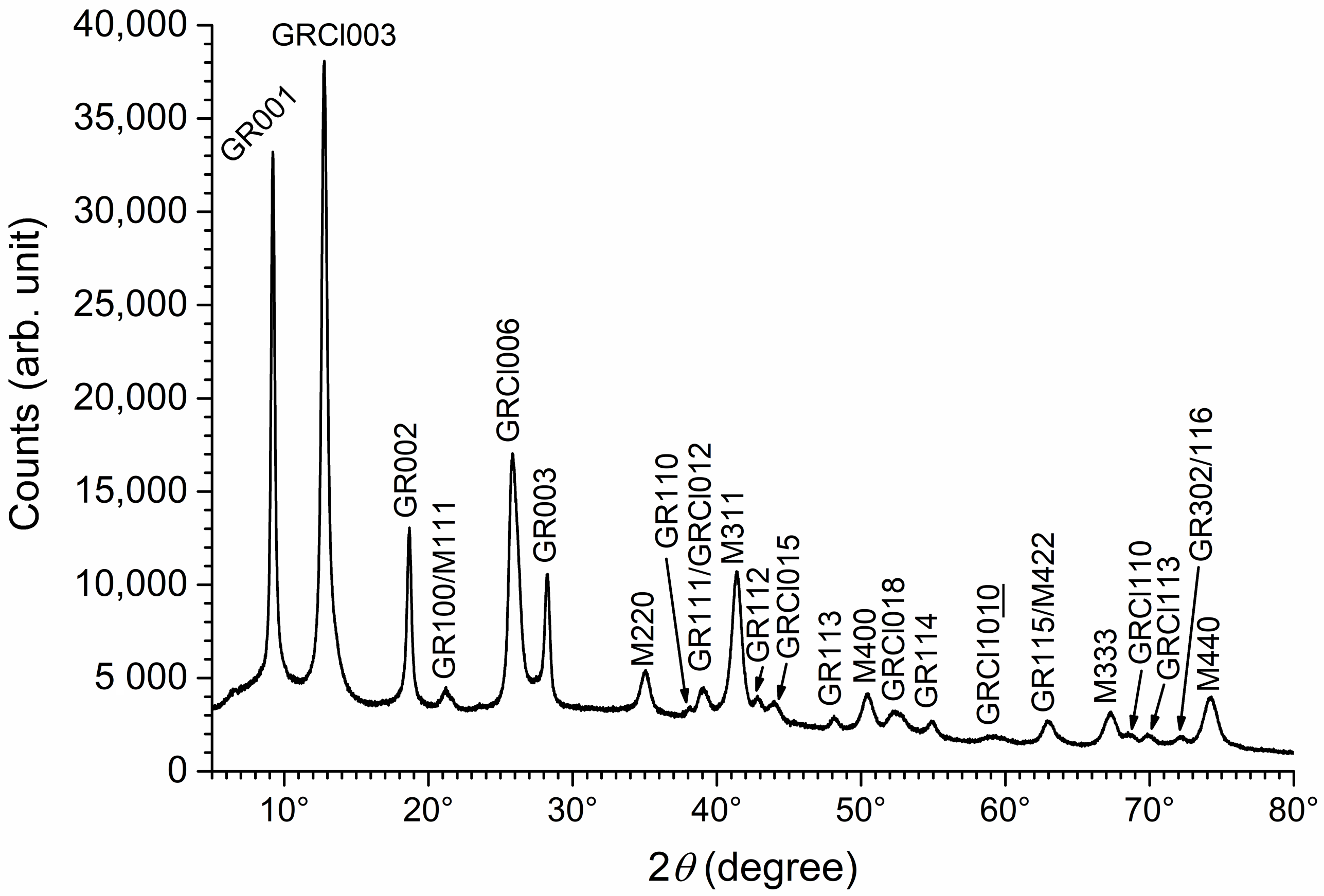
Figure 1 displays the XRD pattern of precipitate M0 after 1 week of ageing. In this first case, Mg(II) cations were not present and the obtained compound is then a Fe(II)-Fe(III) LDH.
In agreement with the previous work [11], the XRD pattern reveals that the solid phase is mainly composed of GR(SO42−), i.e., the Fe(II)-Fe(III) SO4-LDH. The two main peaks of the chloride green rust are seen together with those of GR(SO42−), but their intensity is very low. Using the fitting procedure described in Section 2.2, the intensity ratio between the main peak of GR(SO42−) (GR001, at 2θ = 9.2°) and the main peak of GR(Cl) (GRCl003, at 2θ = 12.9°) is determined at 93:1.
Figure 2 displays the XRD pattern of precipitate M4 after 1 week of ageing. This second case corresponds to the situation where Fe(II) cations are not present. The obtained compound is consequently a Mg(II)-Fe(III) LDH. Strikingly, its XRD pattern drastically differs from that of GR(SO42−). The main diffraction peak, which corresponds to the distance between two consecutive Fe planes in the LDH structure, is located at about 2θ = 13°. This leads to an interplanar distance of 8 Å, rather typical of GR(Cl). By comparison, the main diffraction peak of GR(SO42−) is found at 9.2° (Figure 1), which corresponds to an interplanar distance of 11.15 Å. The diffraction peaks of the obtained Mg(II)-Fe(III) LDH actually correspond to the mineral iowaite, that is the Mg(II)-Fe(III) Cl-LDH similar to GR(Cl) [14,15] with the chemical formula Mg6Fe2(OH)16Cl2·4H2O [15]. In the experimental conditions considered here, when Mg(II) is substituted for Fe(II), a Cl-LDH is formed rather than a SO4-LDH. Note that the solid phase was analyzed as a dry powder so that the diffraction lines of NaCl are also seen.
It can finally be observed that the diffraction peaks of the obtained iowaite are much broader than those of the sulfated GR obtained in the absence of Mg(II) (Figure 1). This shows that the average crystal size, or more exactly the mean coherent domain size, of the Mg(II)-Fe(III) Cl-LDH is much smaller than that of GR(SO42−), i.e., the Fe(II)-Fe(III) SO4-LDH.
The XRD pattern of the precipitate obtained with equal amounts of Fe(II) and Mg(II), i.e., precipitate M2, is displayed in Figure 3. Both GR(SO42−) and GR(Cl) are identified, and found in similar proportions according to the respective intensity of their main peaks. Note that both compounds are likely to comprise not only Fe(II) cations, but Mg(II) cations too. Consequently, they may not be green rust compounds sensu stricto. However, for clarity, this terminology will be used in the following to designate the FeII-(MgII)-FeIII SO4-LDH and Cl-LDH.
Magnetite, the Fe(II-III) mixed valence oxide with chemical formula Fe3O4, is also identified. This shows that the presence of Mg(II) cations has induced in this case the formation of both GR(Cl) and Fe3O4.
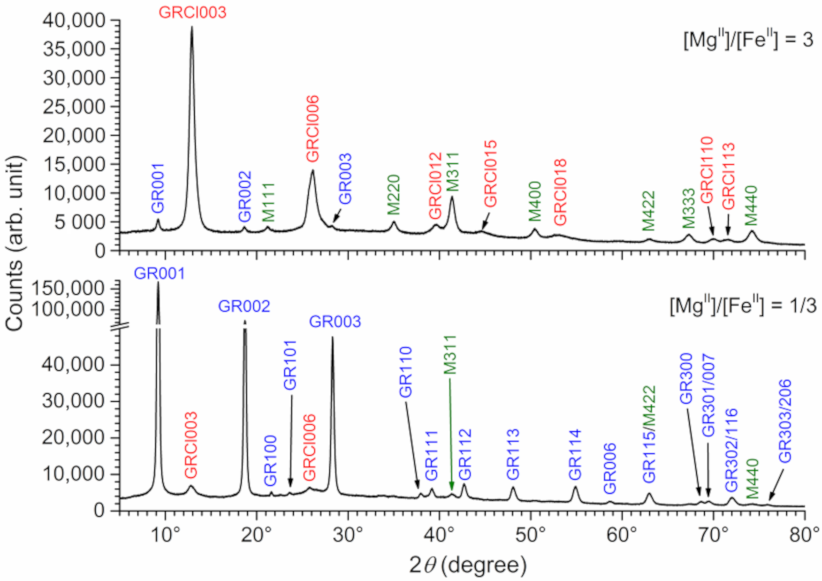
Figure 4 displays the XRD patterns of precipitates M1 and M3 after 1 week of ageing. These data confirm that Mg(II) favors the formation of GR(Cl) and magnetite. Actually, for the high substitution ratio [MgII]/[FeII] = 3 (precipitate M3), the main obtained LDH is GR(Cl). The intensity of the diffraction peaks of GR(SO42−) is very weak, even with respect to that of the main peak of magnetite (M311, at 2θ = 41.3°). The intensity ratio between the main peak of GR(SO42−) and the main peak of GR(Cl) is now determined at 1:32. Conversely, for the low substitution ratio [MgII]/[FeII] = 1/3 (precipitate M1), the diffraction peaks of both GR(Cl) and magnetite remain very small. However, the intensity ratio between the main peak of GR(SO42−) and the main peak of GR(Cl) is equal to 22:1 in this case, while it was 93:1 in the absence of Mg(II) cations. The influence of Mg(II) is small but nonetheless detectable.
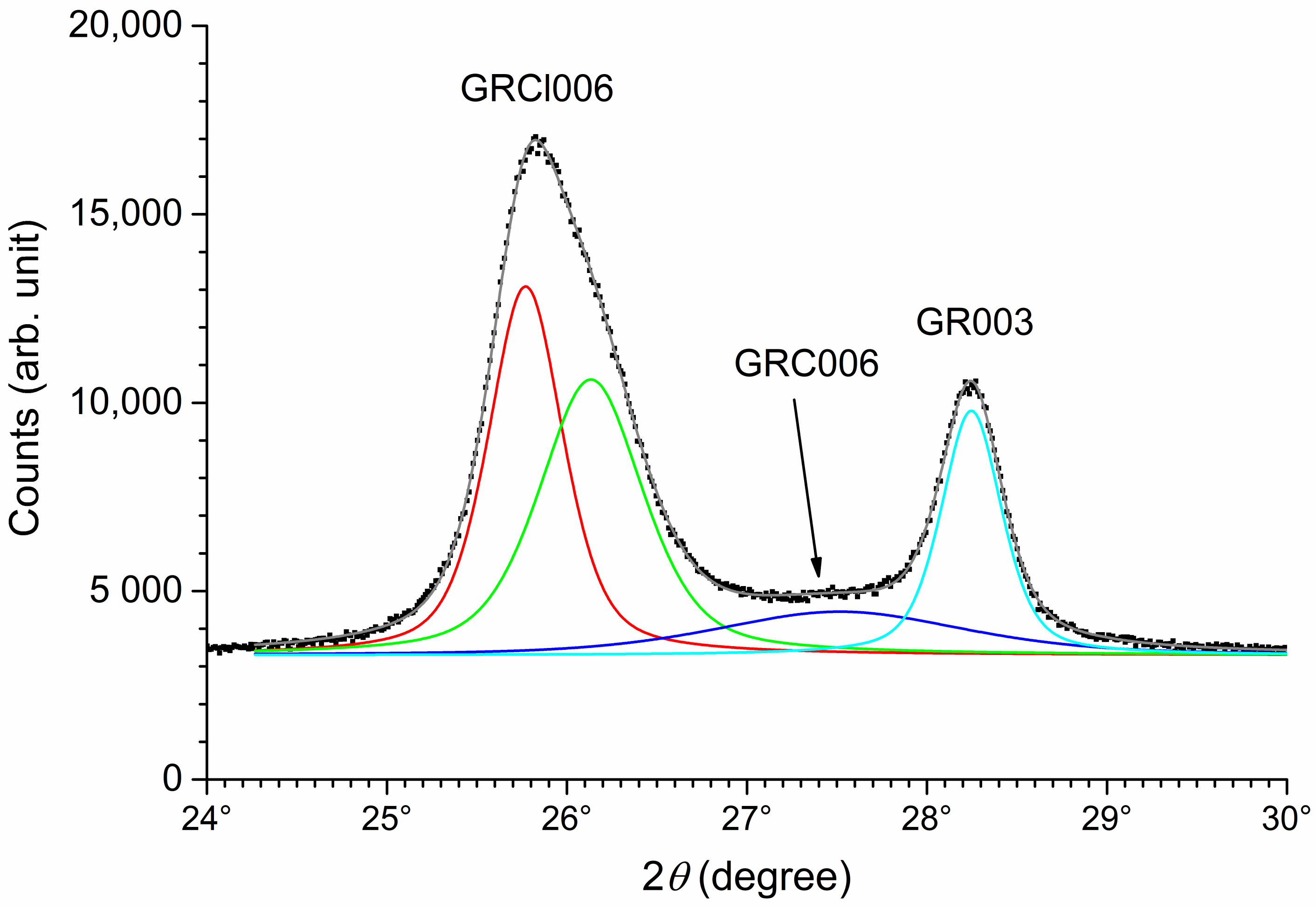
A detailed analysis of the XRD data was achieved to obtain further information, in particular about a possible variation of the GR lattice parameters with the Mg(II):Fe(II) concentration ratio. For that purpose, the angular regions where the two main peaks of GR(SO42−) and GR(Cl) are present were computer fitted (see Section 2.2). The result obtained for precipitate M2 in the 24–30° 2θ region of the GRCl006 peak is displayed in Figure 5 as an example.
Since the GRCl006 peak overlaps slightly with the GR003 peak, both peaks were taken into account. However, the experimental curve could not be adequately fitted and an additional broad peak had to be added. The position of this peak was determined through the fitting procedure at 2θ = 27.52°, a diffraction angle associated with an interplanar distance of 3.76 Å. It corresponds exactly to the 006 diffraction peak of the carbonated green rust GR(CO32−) [13,16]. This finding actually shows that a very small amount of GR(CO32−) has formed together with GR(SO42−), GR(Cl), and magnetite, although carbonate species were not added specifically to the system. These carbonate species could originate in (i) the dissolution of CO2 in the solution and (ii) some impurities present in the chemicals used. It happened that the NaOH pellets used for this study contained a small proportion of Na2CO3.
However, the presence of the weak GRC006 peak cannot explain the important asymmetry of the 006 diffraction peak of GR(Cl). As it can be seen in Figure 5, the computer fitting procedure had to be achieved with two pseudo-Voigt functions in the case of the GRCl006 diffraction peak. Such an asymmetry was not observed for the diffraction peaks of GR(SO42−), as illustrated by the GR003 peak in Figure 5.
All the results obtained with the fitting of the XRD patterns are listed in Table 2. The data corresponding to the traces of carbonate GR, identified in each case, are omitted as they are only the consequence of the presence of carbonate traces (CO2 and impurities) in the system.
First, these results show that the 001 and 002 interplanar distances of GR(SO42−), linked to the c parameter of the hexagonal cell, are not influenced by the [MgII]/[FeII] substitution ratio. They vary slightly around an average of 11.16 ± 0.02 Å for d001 and 5.52 ± 0.01 Å for d002 with no apparent link with [MgII]/[FeII]. However, a clear trend is observed for the width of those peaks. FWHM increases significantly with the proportion of Mg(II), which shows that the growth of the GR(SO42−) crystals, and/or the increase of crystallinity of GR(SO42−), is hindered by the presence of the Mg(II) cations.
In contrast, more important changes are observed for the diffraction peaks of GR(Cl). The data obtained for precipitate M4, that is for the Mg(II)-Fe(III) Cl-LDH, are indeed characteristic of iowaite [14]. It can then be noted that the lattice parameters of iowaite differ from those of GR(Cl). The d003 and d006 interplanar distances are linked to the c parameter of the conventional hexagonal cell. They lead to an average c/3 value of 8.11 ± 0.03 Å (average of d003 and 2 × d006) comparable to the values reported in previous works for iowaite, which are between 8.04 [14] and 8.11 Å [15]. The c/3 parameter of GR(Cl) is smaller, about 7.95 Å [17].
The main peak GRCl003 of the chloride GR, though slightly asymmetric, could be fitted in any case with only one pseudo-Voigt function. However, the corresponding interplanar distance was observed between 7.96 Å for M3 and 8.04 Å for M2, and up to 8.14 Å for M4. The two extreme values are typical of GR(Cl) and iowaite [14,15,17]. The important asymmetry of the GRCl006 diffraction peak implied the use of two pseudo-Voigt functions. Actually, variations of dhkl are associated with larger variations of 2θhkl in the angular region corresponding to the GRCl006 peak, which may explain that the asymmetry of the GRCl003 peak was smaller. The phenomenon was more pronounced in the case of precipitate M2 (Figure 5) and led to two peaks with a similar intensity (Table 2). The corresponding d006 distances were determined at 4.01–4.02 and 3.95–3.96 Å. They lead to values of 8.03 ± 0.01 and 7.91 ± 0.01 Å, respectively. Though the asymmetry of the GRCl006 peak may have various origins, a heterogeneous Mg(II) content could lead to a variation of the c lattice parameter of the conventional hexagonal cell, this parameter increasing with the Mg(II) content, as illustrated by the difference between the c lattice parameter of GR(Cl) and that of iowaite.
The width of the GRCl peaks also varies with the [MgII]/[FeII] substitution ratio. As already noted, FWHM is very high in the absence of Fe(II), that is for iowaite. The influence of Mg(II) is also illustrated by the increase of FWHM from M2 to M3. However, the width of the GR(Cl) peaks is larger for M1 even though the [MgII]/[FeII] ratio is smaller.

3.2. XRD Analysis of Unaged Precipitates

Some solid phases may result from the precipitation reactions, while other phases may form during ageing via the transformation of initially precipitated compounds. The evolution with time of precipitate M0, previously studied [11], showed, for instance, that the amount of GR(Cl) decreased upon ageing, which implied that part of the initially formed GR(Cl) transformed to GR(SO42−). Consequently, only traces of GR(Cl) remained after 1 week (as seen in Figure 1). Similarly, it was observed that, in the absence of excess dissolved Fe(II) species, part of the initially precipitated GR(SO42−) could transform into magnetite [11].
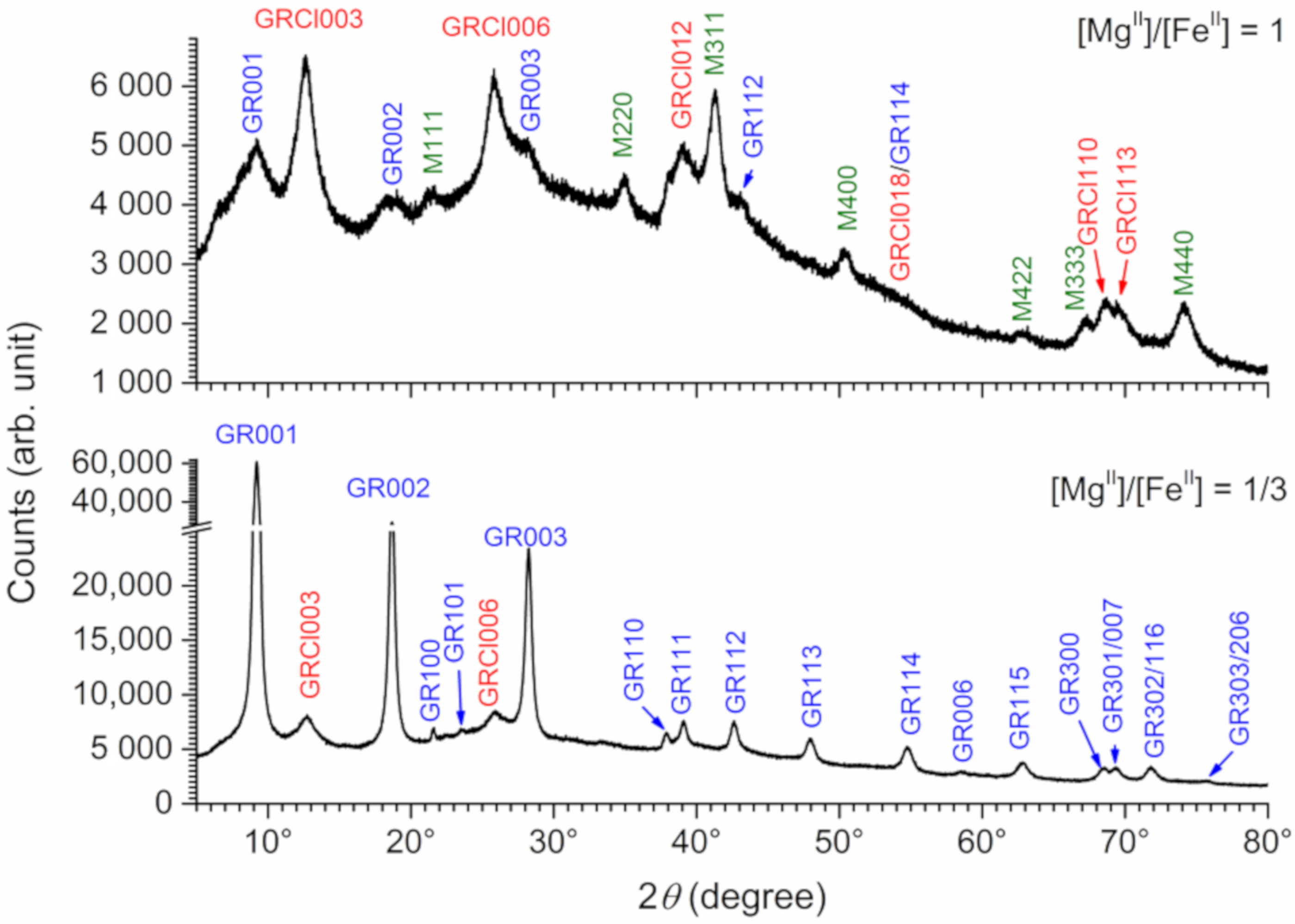
Figure 6 displays the XRD patterns of unaged precipitates M1 and M2. In both cases, the diffraction peaks are clearly broader than those of the aged compounds (Figure 3 and Figure 4). This illustrates a well-known effect of ageing, i.e., the increase of crystallinity and crystal size with time. In the case of M1, only two phases are detected, namely GR(SO42−) and GR(Cl). After 1 week of ageing, magnetite was present. This result shows that magnetite results in this case from the ageing procedure. The intensity ratio between the main peak of GR(SO42−) and the main peak of GR(Cl) is determined before ageing at 5.5:1. It was determined (see previous Section 3.1) at 22:1 after 1 week of ageing. This shows that the proportion of GR(Cl) decreased significantly during ageing, as observed for M0 [11], i.e., in the absence of Mg(II) cations. For the lowest [MgII]/[FeII] ratio of 1/3, GR(Cl) may then have also transformed to GR(SO42−).
In the case of M2, magnetite is already present among the solid phases that compose the unaged precipitate. Consequently, the three phases observed after ageing, i.e., GR(SO42−), GR(Cl), and Fe3O4, result from the precipitation process. The intensity ratio between the main peak of GR(SO42−) and the main peak of GR(Cl) is determined at 1:1.5 for the unaged precipitate and 1:1.8 for the aged precipitate (Figure 3). The variation is slight and may not be significant. In any case, it shows that the proportion of GR(Cl) remained constant or increased slightly upon ageing, in contrast with what was observed without Mg(II) (precipitate M0, [11]) or with the lowest [MgII]/[FeII] substitution ratio (precipitate M1). This shows that the presence of Mg(II) not only favors the precipitation of the Cl-LDH, but also increases its stability with respect to the SO4-LDH.

3.3. Analysis of the Mg(II)-Fe(III) Solid Phases Obtained in the Absence of Chloride

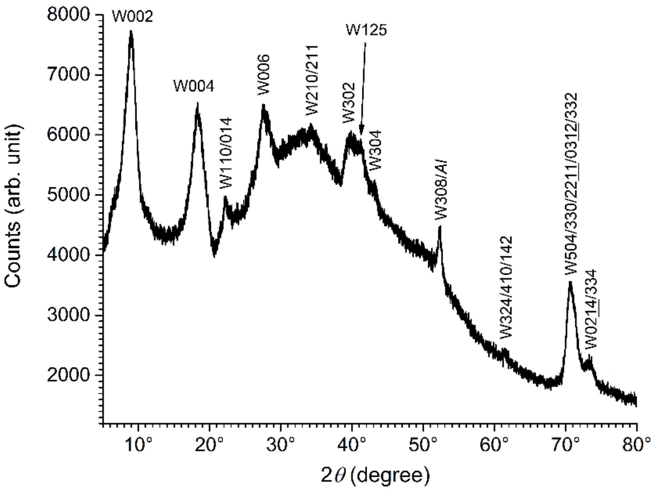
The first XRD pattern, shown in Figure 7, is that of precipitate M4s aged 1 week and analyzed immediately after filtration as a wet paste. The obtained Mg(II)-Fe(III) compound is poorly crystallized and its pattern is similar to that of GR(SO42−), i.e., the main diffraction peak is located at 9.0°. This pattern was indexed according to the ICCD-JCPDS file of wermlandite Mg7Al1,14Fe0,86(OH)18Ca0,6Mg0,4(SO4)2(H2O)12, a mineral structurally similar to GR(SO42−) [18]. Wermlandite includes Al3+ and Ca2+ ions and not only Mg2+ and Fe3+ cations. In our experiment, Al3+ and Ca2+ ions were not present and the obtained compound is then a Mg(II)-Fe(III) SO4-LDH. Other SO4-LDH are also characterized by this type of structure, where two consecutive metal cations planes are separated by ~11 Å. An example is hydrohonnessite, where the cations present in the hydroxide layers are Ni2+ and Fe3+ [19].
This result clearly shows that a Mg(II)-Fe(III) SO4-LDH similar to GR(SO42−) can be obtained if Cl ions are not available for the formation of a Cl-LDH. The distance between two consecutive planes of metal cations is determined at 11.56 Å, which shows that, as for the Cl-LDH, the substitution of Fe(II) by Mg(II) cations leads to an increase of the c lattice parameter of the hexagonal cell. Actually, the ionic radius of Mg(II) is smaller than that of Fe(II) [20], which induces a decrease of the a lattice parameter of Mg(II)-Fe(III) LDHs with respect to Fe(II)-Fe(III) LDHs [21]. However, the c lattice parameter is nonetheless higher with Mg(II) [21]. This illustrates how the cationic composition of the hydroxide layer influences the electrostatic interactions that bind together the hydroxide sheets and the interlayers and ensures the stability of the crystal structure [21]. This crucial point is further discussed in Section 4.
The second XRD pattern, shown in Figure 8, was obtained with the same aged M4s precipitate. However, the wet paste obtained after filtration was dried in air and the solid phase was analyzed as a dry powder 10 days later. The result of the drying is a change in the structure of the Mg(II)-Fe(III) SO4-LDH. This new compound can be considered as a second form of SO4-LDH and will be called in the following the Mg(II)-Fe(III) hydroxysulfate-b. Its new structure seems similar to that of GR(Cl) and iowaite and was then indexed similarly. The main peak of the Mg(II)-Fe(III) hydroxysulfate-b is then the 003 peak. Actually, this second type of SO4-LDH was already reported [19]. Honessite, a Ni(II)-Fe(III) SO4-LDH, for example, is characterized by a distance between two consecutive planes of metal cations of 8.7 Å [19].
The main diffraction peak of the Mg(II)-Fe(III) hydroxysulfate-b obtained here is located at a position 2θ = 11.74°. This corresponds to a c/3 distance of 8.75 Å, very similar to that of honessite. The transformation from one type of structure to the other, associated with the drying of the solid phase, is due to the release of water molecules initially present in the interlayers [22].

4. Discussion

In the considered experimental conditions, SO42− and Cl were the only anions available for the formation of LDH compounds. Consequently, the only Fe(II)-Fe(III) mixed valence compounds that could possibly form were GR(SO42−), GR(Cl), and Fe3O4. The traces of GR(CO32−) detected in each case are due to CO2 and/or chemical impurities and the formation of this phase will not be further discussed. These experimental conditions were chosen so that in the absence of Mg(II) cations, the Fe(II)-Fe(III) SO4-LDH, i.e., GR(SO42−), was obtained, only accompanied by traces of the Fe(II)-Fe(III) Cl-LDH, i.e., GR(Cl). The aim was to reproduce the first stage of the corrosion process of carbon steel in seawater, which leads to GR(SO42−) [1,2], via a precipitation reaction involving dissolved Fe(II) and Fe(III) species, OH- ions, and the main anionic species of seawater, i.e., Cl and SO42−.
The first and more important effect of Mg(II) cations is to favor the formation of a Cl-LDH at the detriment of the SO4-LDH obtained with Fe(II) and Fe(III). This is clearly illustrated by the increase of the proportion of GR(Cl) with the increase of the [MgII]/[FeII] substitution ratio and the formation of iowaite, the Mg(II)-Fe(III) Cl-LDH, when [FeII] = 0.
A Mg(II)-Fe(III) SO4-LDH could be obtained when Cl ions were removed from the system. However, the solid phase identified in an aqueous suspension, structurally similar to GR(SO42−), underwent a transformation upon drying, which led to a SO4-LDH structurally closer to GR(Cl).
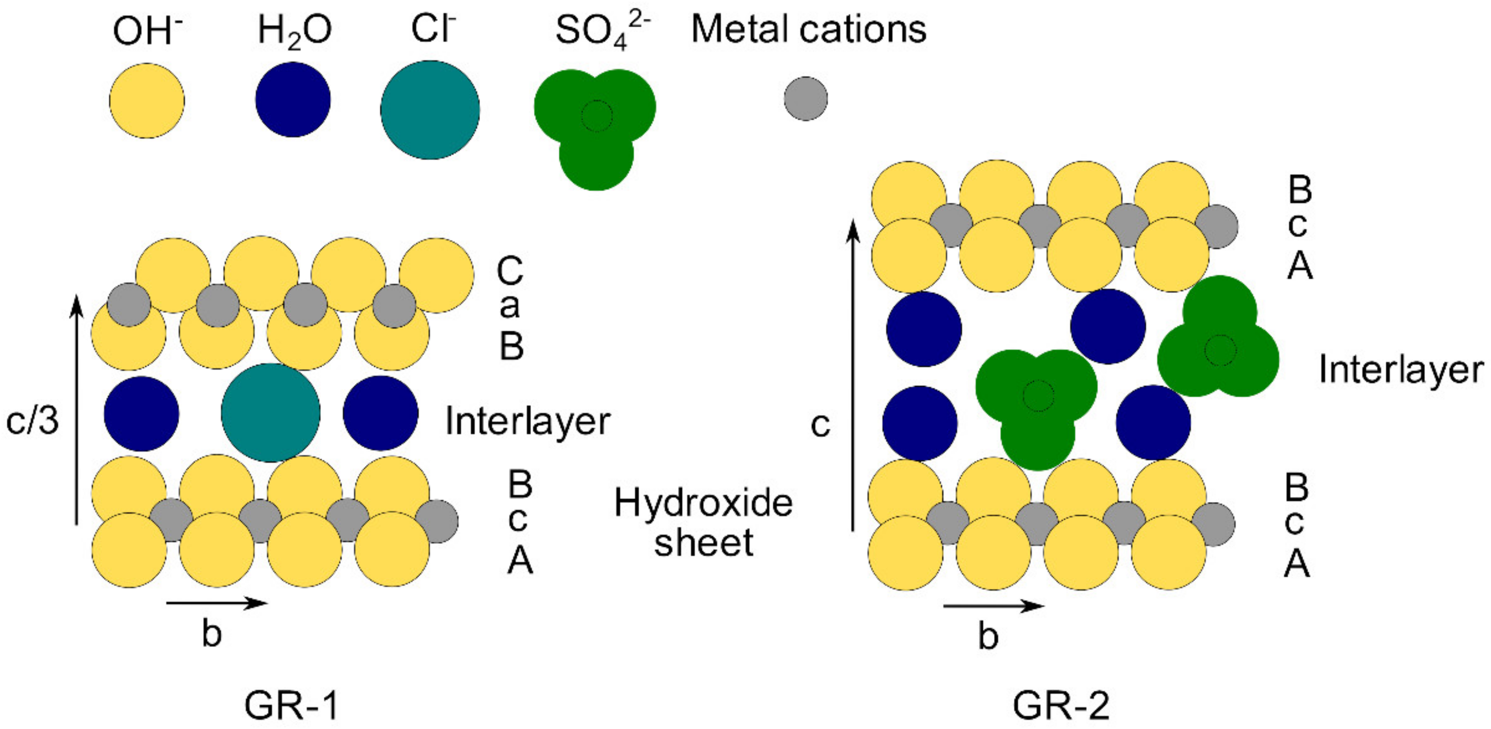
The main difference between the two GR structures is the organization of the interlayers, that involve two planes of anions and water molecules in GR(SO42−) [23] and only one plane in GR(Cl) [17] (and in GR(CO32−), as well). Figure 9 displays a schematic representation of these structures. GR(Cl) and GR(SO42−) were initially called GR-1 and GR-2 [24] and a similar terminology can be retained to distinguish the structure of GR(Cl) and GR(CO32−) from that of GR(SO42−). It must be noted that for the GR-1 rhombohedral R 3 ¯ m structure of GR(Cl) [17], the stacking sequence is AcB i BaC i CbA i, where A, B, C are planes of OH ions, a, b, c planes of Fe atoms, and i corresponds to the interlayers. In the case of the P 3 ¯ m1 trigonal structure of GR(SO42−) [23], i.e., GR-2, the stacking sequence is AcB i AcB.
The results obtained here show that Mg(II) cations favor the GR-1 structure. From a fundamental point of view, the cohesion of a LDH structure is due to (i) the water molecules of the interlayers that interact with the adjacent hydroxide layers and the intercalated anions via hydrogen bonds and (ii) the intercalated anions that interact with the hydroxide layers via electrostatic interactions and hydrogen bonds [21,25]. Changes in the hydroxide layers necessarily have an influence on the bonds linking these layers and the species (anions and water molecules) present in the interlayers. They have thus an influence on the cohesion of the LDH structure. The dependence between the cationic composition of the hydroxide layer and the structural stability has been studied and modelled in [21]. This study demonstrated how important the nature of cations for the stability of the crystal structure was.
The thorough analysis of the diffraction data showed that the c lattice parameter of GR(SO42−) did not vary with the [MgII]/[FeII] substitution ratio. However, the distance between two planes of metal cations is higher for the Mg(II)-Fe(III) SO4-LDH, with 11.56 Å vs. 11.16 Å for GR(SO42−) (Table 2). In contrast, the diffraction peaks of GR(Cl) proved to be influenced by the [MgII]/[FeII] ratio. This suggests that the Mg(II) cations are not present, or only in a small amount, in the hydroxide layers of GR(SO42−). Consequently, they would be preferentially incorporated in the GR(Cl) structure or left in the solution. The small amount of Mg(II) possibly present in the hydroxide layers of GR(SO42−) would explain the decrease of crystal/mean coherent domain size observed with the increasing Mg(II)/Fe(II) concentration ratio (Table 2).
An interesting first case is the [MgII]/[FeII] ratio of 1/3. With this Mg(II) amount, only a minor proportion of GR(Cl) is present after 1 week of ageing, while 25% of Fe(II) is substituted by Mg(II). According to the initial amounts of reactants, the precipitation reaction could be written as:
9 2 Fe 2 +   +   3 2 Mg 2 +   +   2 Fe 3 +   +   12 OH   +   SO 4 2   +   8 H 2 O     Fe II 4 Fe III 2 ( OH ) 12 SO 4 · 8 H 2 O   +   1 2 Fe 2 +   +   3 2 Mg 2 +
This writing shows that for this [MgII]/[FeII] ratio, all the Mg2+ ions could be released into the solution, more likely during the ageing procedure where GR(Cl) transforms to GR(SO42−). It can then be forwarded that in this first case, the SO4-LDH is close to GR(SO42−) and contains a very small proportion of Mg(II). The GR-2 structure is obtained since Mg(II) cations are preferentially found in the solution and in the small amount of the remaining GR(Cl) (or more exactly Cl-LDH).
In contrast, for the higher [MgII]/[FeII] ratios of 1 and 3, an important amount of Mg(II) is necessarily incorporated in the solid phase, which implies that the GR-1 structure is favored leading to the predominance of the Cl-LDH similar to GR(Cl). Both GR(Cl) and iowaite are characterized by a (Fe,Mg)(II) to Fe(III) cation ratio of 3:1 [14,16], which implies that all divalent cations should be incorporated into the solid phase in the considered experimental conditions. For instance, for the highest [MgII]/[FeII] ratio considered here, the precipitation reaction of the Cl-LDH can be written, neglecting the small amount of GR(SO42−) that forms, as:
3 2 Fe 2 +   +   9 2 Mg 2 +   +   2 Fe 3 +   +   16 OH   +   2 Cl   +   4 H 2 O     Fe II 1.5 Mg II 4.5 Fe III 2 ( OH ) 16 Cl 2 · 4 H 2 O
However, Mg(II) cations also promoted the formation of magnetite. Looking to reaction (4), it is seen that in the considered experimental conditions, which correspond to a (Fe,Mg)(II) to Fe(III) cation ratio of 3:1, the precipitation of a Cl-LDH having the same (Fe,Mg)(II) to Fe(III) cation ratio of 3:1 does not leave any divalent cations in the solution. In a previous study [11], it was demonstrated that in this case, the ageing of the suspension led to the formation of magnetite. Moreover, it must be noted that the experimental conditions considered here correspond to an [OH] to [FeII+MgII+FeIII] ratio of 3 to 2. Reaction (4) requires an [OH] to [FeII+MgII+FeIII] ratio of 4 to 2. Consequently, both divalent and trivalent cations are in excess with respect to the OH ions available. It can then be forwarded that the excess Fe(II) and Fe(III) cations react with water molecules to form a small proportion of magnetite, according to the following reaction:
Fe2+ + 2Fe3+ + 4H2O → FeIIFeIII2 O4 + 8H+
The present findings can be connected with more applied aspects of marine corrosion and cathodic protection of steel structures. Actually, the concentration of Mg2+ in seawater is important, about 0.053 mol/kg [10]. Therefore, the smallest [MgII]/[FeII] ratio of 1/3 considered here would correspond to a Fe2+ concentration of 0.16 mol/kg in the bulk seawater, which is rather high. However, GR(SO42−) is the main GR compound identified in the corrosion product layers formed on steel immersed in seawater [1,2,5,6,7]. At the vicinity of the steel/seawater interface, where the Fe2+ cations are produced, the [MgII]/[FeII] ratio is necessarily lower than in the bulk seawater and it can be forwarded that the formation of GR(SO42−) only takes place close to the steel surface.
Our results also explain more clearly why an anodic polarization favors the formation of GR(SO42−) with respect to any other Fe(II,III) mixed valence compounds [1,7]. An anodic polarization decreases the interfacial [MgII]/[FeII] ratio and thus prevents the influence of Mg2+ cations.
In contrast, pyroaurite, the Mg(II)-Fe(III) CO3-LDH was observed on a steel surface under cathodic protection [9]. In this case, due to the low dissolution rate of iron, the [MgII]/[FeII] ratio is necessarily higher, even at the steel/seawater interface. The increase of the interfacial pH associated with the cathodic polarization tends to favor GR(CO32−) with respect to GR(SO42−) [8] even if Mg2+ cations are not present. However, the formation of the Mg(II)-Fe(III) LDH rather than the Fe(II,III) LDH confirms that Mg(II) cations can favor the formation of LDH phases characterized by the GR1-structure, i.e., Cl-LDH and CO3-LDH.

5. Conclusions

  • For [MgII]/[FeII] ratios higher than 1, the influence of Mg(II) is strong and induces the formation of GR(Cl) and magnetite. In the absence of Fe(II), the Mg(II)-Fe(III) Cl-LDH, i.e., iowaite, is the only solid phase obtained.
  • The influence of Mg2+ cations on the formation of the sulfated GR is not significant up to a [MgII]/[FeII] ratio of 1/3, where only a slight increase of the proportion of GR(Cl) is observed. In the absence of Mg(II), only GR(SO42−) is obtained, with only traces of GR(Cl), in agreement with the previous work [11].
  • It is forwarded that the presence of Mg2+ cations in the hydroxide layers of the LDH structure of GR compounds favors the Cl- and CO3-GR-1 structure, thus hindering the formation of the SO4-GR-2 structure.

Author Contributions

Conceptualization, P.R., M.J., and R.S.; methodology, P.R., M.J., and R.S.; validation, P.R, J.D., K.A., R.S., and M.J.; formal analysis, P.R, J.D., K.A., R.S., and M.J.; investigation, P.R, J.D., K.A., R.S., and M.J.; writing—original draft preparation, P.R.; writing—review and editing, P.R., M.J., and R.S.; visualization, P.R. and J.D.; supervision, P.R., M.J., and R.S.; project administration, P.R., M.J., and R.S.; funding acquisition, P.R. All authors have read and agreed to the published version of the manuscript.

Funding

European Regional Development Fund (ERDF) and the CDA of La Rochelle through the DYPOMAR research project and the thesis of Julien Duboscq.

Data Availability Statement

The data presented in this study are available on request from the corresponding author. The data are not publicly available because work is still in progress on the subject.

Conflicts of Interest

The authors declare no conflict of interest.

References

  1. Refait, P.; Grolleau, A.-M.; Jeannin, M.; Rémazeilles, C.; Sabot, R. Corrosion of carbon steel in marine environments: Role of the corrosion product layer. Corros. Mater. Degrad. 2020, 1, 198–218. [Google Scholar] [CrossRef]
  2. Lanneluc, I.; Langumier, M.; Sabot, R.; Jeannin, M.; Refait, P.; Sablé, S. On the bacterial communities associated with the corrosion product layer during the early stages of marine corrosion of carbon steel. Int. Biodeterior. Biodegrad. 2015, 99, 55–65. [Google Scholar] [CrossRef]
  3. Detournay, J.; De Miranda, L.; Dérie, R.; Ghodsi, M. The region of stability of green rust II in the electrochemical potential-pH equilibrium diagram of iron in sulphate medium. Corros. Sci. 1975, 15, 295–306. [Google Scholar] [CrossRef]
  4. Olowe, A.; Génin, J. The mechanism of oxidation of ferrous hydroxide in sulphated aqueous media: Importance of the initial ratio of the reactants. Corros. Sci. 1991, 32, 965–984. [Google Scholar] [CrossRef]
  5. Pineau, S.; Sabot, R.; Quillet, L.; Jeannin, M.; Caplat, C.; Dupont-Morral, I.; Refait, P. Formation of the Fe(II-III) hydroxy-sulphate green rust during marine corrosion of steel associated to molecular detection of dissimilatory sulphite-reductase. Corros. Sci. 2008, 50, 1099–1111. [Google Scholar] [CrossRef]
  6. Duan, J.; Wu, S.; Zhang, X.; Huang, G.; Du, M.; Hou, B. Corrosion of carbon steel influenced by anaerobic biofilm in natural seawater. Electrochim. Acta 2008, 54, 22–28. [Google Scholar] [CrossRef]
  7. Refait, P.; Grolleau, A.-M.; Jeannin, M.; François, E.; Sabot, R. Localized corrosion of carbon steel in marine media: Galvanic coupling and heterogeneity of the corrosion product layer. Corros. Sci. 2016, 111, 583–595. [Google Scholar] [CrossRef]
  8. Refait, P.; Jeannin, M.; Sabot, R.; Antony, H.; Pineau, S. Electrochemical formation and transformation of corrosion products on carbon steel under cathodic protection in seawater. Corros. Sci. 2013, 71, 32–36. [Google Scholar] [CrossRef]
  9. Refait, P.; Jeannin, M.; Sabot, R.; Antony, H.; Pineau, S. Corrosion and cathodic protection of carbon steel in the tidal zone: Products, mechanisms and kinetics. Corros. Sci. 2015, 90, 375–382. [Google Scholar] [CrossRef]
  10. Riley, J.P.; Chester, R. Introduction to Marine Chemistry; Academic Press: London, UK, 1971. [Google Scholar]
  11. Refait, P.; Sabot, R.; Jeannin, M. Role of Al(III) and Cr(III) on the formation and oxidation of the Fe(II-III) hydroxysulfate green rust. Colloids Surf. A Phys. Eng. Asp. 2017, 531, 203–212. [Google Scholar] [CrossRef]
  12. Boucherit, M.N.; Goff, A.H.-L.; Joiret, S. Raman studies of corrosion films grown on Fe and Fe-6Mo in pitting conditions. Corros. Sci. 1991, 32, 497–507. [Google Scholar] [CrossRef]
  13. Hansen, H.C.B. Composition, stabilisation, and light absorption of Fe(II)-Fe(III) hydroxycarbonate (green rust). Clay Miner. 1989, 24, 663–669. [Google Scholar] [CrossRef]
  14. Braithwaite, R.S.W.; Dunn, P.J.; Pritchard, R.G.; Paar, W.H. Iowiate, a re-investigation. Miner. Mag. 1994, 58, 79–85. [Google Scholar] [CrossRef]
  15. Kohls, D.W.; Rodda, J.L. Iowaite, a new hydrous magnesium hydroxide-ferric oxychloride from the precambrian of iowa. Am. Miner. 1967, 52, 1261–1271. [Google Scholar]
  16. McGill, I.R.; McEnaney, B.; Smith, D.C. Crystal structure of green rust formed by corrosion of cast iron. Nat. Cell Biol. 1976, 259, 200–201. [Google Scholar] [CrossRef]
  17. Refait, P.; Abdelmoula, M.; Génin, J.-M. Mechanisms of formation and structure of green rust one in aqueous corrosion of iron in the presence of chloride ions. Corros. Sci. 1998, 40, 1547–1560. [Google Scholar] [CrossRef]
  18. Rius, J.; Allmann, R. The superstructure of the double layer mineral wermlandite [Mg7(Al0.57, Fe3+0.43) (OH)18]2+ [(Ca0.6, Mg0.4) (SO4)2(H2O)12]2−. Z. Für Krist. Cryst. Mater. 2015, 168, 133–144. [Google Scholar]
  19. Bookin, A.S.; Cherkashin, V.I.; Drits, V.A. Polytype diversity of the hydrotalcite-like minerals II: Determination of the polytypes of experimentally studied varieties. Clays Clay Miner. 1993, 41, 558–564. [Google Scholar] [CrossRef]
  20. Shannon, R.D. Revised effective ionic radii and systematic studies of interatomic distances in halides and chalcogenides. Acta Cryst. 1976, 32, 751–767. [Google Scholar] [CrossRef]
  21. Grégoire, B.; Ruby, C.; Carteret, C. Structural cohesion of MII-MIII layered double hydroxides crystals: Electrostatic forces and cationic polarizing power. Cryst. Growth Des. 2012, 12, 4324–4333. [Google Scholar] [CrossRef]
  22. Khaldi, M.; De Roy, A.; Chaouch, M.; Besse, J. New varieties of zinc–chromium–sulfate lamellar double hydroxides. J. Solid State Chem. 1997, 130, 66–73. [Google Scholar] [CrossRef]
  23. Simon, L.; François, M.; Refait, P.; Renaudin, G.; Lelaurain, L.; Génin, J.M. Structure of the Fe(II-III) layered double hydroxysulphate green rust two from Rietveld analysis. Solid State Sci. 2003, 5, 327–334. [Google Scholar] [CrossRef]
  24. Bernal, J.D.; Dasgupta, D.R.; Mackay, A.L. The oxides and hydroxides of iron and their structural inter-relationships. Clay Min. Bull. 1959, 4, 15–30. [Google Scholar] [CrossRef]
  25. Galvão, T.L.P.; Neves, C.S.; Caetano, A.P.F.; Maia, F.; Mata, D.; Malheiro, E.; Ferreira, M.J.; Bastos, A.C.; Salak, A.N.; Gomes, J.R.B.; et al. Control of crystallite and particle size in the synthesis of layered double hydroxides: Macromolecular insights and a complementary modeling tool. J. Colloid Interface Sci. 2016, 468, 86–94. [Google Scholar] [CrossRef] [PubMed]
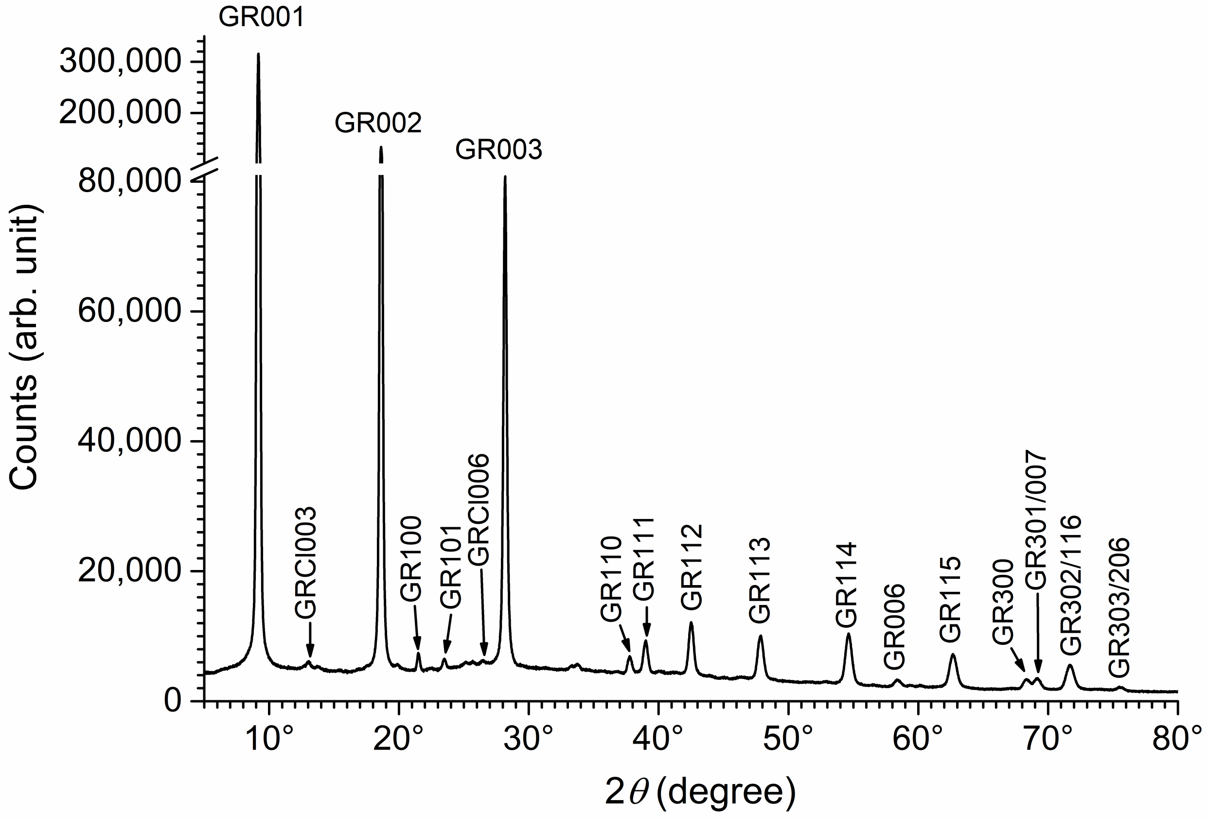
Figure 1. XRD pattern of reference precipitate M0 ([MgII] = 0) after 1 week of ageing at room temperature (RT). GR = GR(SO42−), GRCl = GR(Cl), with the corresponding Miller index.
Cmd 02 00003 g001
Figure 2. XRD pattern of precipitate M4 ([FeII] = 0) after 1 week of ageing at RT. The precipitate was analyzed as a dry powder. Io: Iowaite, H: Halite NaCl, with the corresponding Miller index.
Cmd 02 00003 g002
Figure 3. XRD pattern of precipitate M2 ([MgII]/[FeII] = 1) after 1 week of ageing at RT. GR = GR(SO42−), GRCl = GR(Cl), M = Fe3O4, with the corresponding Miller index.
Cmd 02 00003 g003
Figure 4. XRD pattern of precipitates M1 ([MgII]/[FeII] = 1/3) and M3 ([MgII]/[FeII] = 3) after 1 week of ageing at RT. GR = GR(SO42−), GRCl = GR(Cl), M = Fe3O4, with the corresponding Miller index.
Cmd 02 00003 g004
Figure 5. Fitting of the XRD pattern of precipitate M2 ([MgII]/[FeII] = 1) after 1 week of ageing at RT: Detail of the 24–30° angular region. GR = GR(SO42−), GRCl = GR(Cl), GRC = GR(CO32−), with the corresponding Miller index.
Cmd 02 00003 g005
Figure 6. XRD pattern of unaged precipitates M1 ([MgII]/[FeII] = 1/3) and M2 (MgII]/[FeII] = 1). GR = GR(SO42−), GRCl = GR(Cl), M = Fe3O4, with the corresponding Miller index.
Cmd 02 00003 g006
Figure 7. XRD pattern of precipitate M4s ([FeII] = 0 and [Cl] = 0) after 1 week of ageing at RT. W = Mg(II)-Fe(III) hydroxysulfate similar to wermlandite, with the corresponding Miller index.
Cmd 02 00003 g007
Figure 8. XRD pattern of precipitate M4s ([FeII] = 0 and [Cl] = 0) after 1 week of ageing at RT, filtration, and drying in air (10 days). HSb = Mg(II)-Fe(III) hydroxysulfate-b (see text) with the corresponding Miller index.
Cmd 02 00003 g008
Figure 9. Schematic representations of the GR-1 and GR-2 structures, drawn according to the crystal structures of GR(Cl) given in [17] and GR(SO42−) given in [23].
Cmd 02 00003 g009
Table 1. Concentrations of reactants (mol L−1) used for the various experiments M0–M4.
ReactantsConcentrations (mol L−1)
M0M1M2M3M4M4s 1
NaOH0.240.240.240.240.240.24
NaCl0.190.190.190.190.190
Na2SO4·10H2O0.030.030.030.030.030
FeCl2·4H2O0.120.090.060.0300
MgCl2·4H2O00.030.060.090.120
FeCl3·6H2O0.040.040.040.040.040
MgSO4·7H2O000000.12
Fe2(SO4)3·5H2O000000.12
1 M4s: Specific experiment without Fe(II) and Cl.
Table 2. Characteristics of the two main diffraction peaks of GR(SO42−) and GR(Cl)/iowiate for the aged M0-M4 precipitates; d: Interplanar distance (Å), I: Peak intensity, with I = 100 for the most intense peak of the considered compound, and FWHM: Full width at half maximum, in degrees. GR = GR(SO42−) and GRCl = GR(Cl)/iowaite.
Diffraction PeakParameterM0M1M2M3M4
d11.18 Å11.14 Å11.13 Å11.16 Å-
GR001I100100100100-
FWHM0.21°0.24°0.34°0.35°-
d5.53 Å5.51 Å5.52 Å5.52 Å-
GR002I51514052-
FWHM0.25°0.28°0.36°0.41°-
d-8.01 Å8.04 Å7.96 Å8.14 Å
GRCl003I-100100100100
FWHM-0.80°0.46°0.64°1.53°
d1-4.01 Å4.01 Å4.02 Å4.04 Å
I1-8227757
GRCl006FWHM1-0.80°0.49°0.53°1.79°
d2--3.96 Å3.95 Å-
I2--2835-
FWHM2--0.68°0.81°-
Publisher’s Note: MDPI stays neutral with regard to jurisdictional claims in published maps and institutional affiliations.