Article

Continuous Preparation of Carbon Nanotubes/Carbon Fiber Reinforcement Using Fe-Ni Bimetallic Catalyst

1
Key Laboratory for Liquid-Solid Structural Evolution and Processing of Materials (Ministry of Education), Shandong University, Jinan 250061, China
2
Shandong North Modern Chemical Industry Co., Ltd., Jinan 250061, China
*
Author to whom correspondence should be addressed.
Surfaces 2025, 8(3), 60; https://doi.org/10.3390/surfaces8030060
Submission received: 14 July 2025 / Revised: 20 August 2025 / Accepted: 22 August 2025 / Published: 24 August 2025
(This article belongs to the Special Issue In Situ and Operando Catalyst Characterization)

Abstract

Surface modification of carbon fibers (CFs) is a critical step in preparing carbon fiber-reinforced composites. This study developed a continuous experimental process that integrates electrochemical anodic oxidation and chemical vapor deposition to fabricate carbon nanotubes/carbon fiber (CNTs/CF) reinforcements. The effects of temperature and hydrogen flow rate during CNT growth on the resulting reinforcements were systematically investigated. The surface morphology and mechanical properties of the modified materials were characterized using scanning electron microscopy, Raman spectroscopy, and single-fiber tensile testing. Employing an Fe0.5Ni0.5 bimetallic catalyst under optimized conditions (550 °C, H2 flow rate: 0.45 mol/min, C2H2 flow rate: 0.30 mol/min), the resulting reinforcement exhibited an 8.7% increase in tensile strength compared to as-received CF.

1. Introduction

CFs are widely employed as reinforcing materials in lightweight composites due to their exceptional properties, including high specific modulus, high specific strength, excellent thermal stability, corrosion resistance, and low density [1,2]. As a reinforcement phase, the intrinsic properties of carbon fibers and their interfacial performance with the polymer matrix are the primary factors governing the overall performance of the resulting composites [3]. However, the highly crystalline graphite basal planes on the carbon fiber surface exhibit smooth morphology and are chemically inert, which hinders effective physical adsorption and desired chemical interactions. This leads to poor wettability by the polymer matrix and consequently weak interfacial bonding in unmodified composites [4]. To address this limitation, surface modification of carbon fibers has emerged as an essential processing step to establish a continuous and efficient interfacial structure, thereby enabling the practical application of carbon fiber-reinforced composites (CFRCs) in industrial production [5].
CNTs have demonstrated exceptional potential as reinforcements in carbon fiber composites due to their superior interfacial compatibility with polymer matrices. The synergistic combination of microscale carbon fibers and nanoscale CNTs creates a hierarchical architecture that significantly enhances interfacial characteristics through multiscale mechanical interlocking and chemical interactions [6]. Various surface modification approaches incorporating CNTs have been developed to enhance interfacial bonding characteristics in carbon fiber-reinforced composites. Lee et al. [7] prepared vertically aligned CNT/CF materials via electrophoretic deposition (EPD) under mild conditions and investigated the optimal EPD conditions influencing CNT alignment. Ultimately, they achieved a carbon fiber-reinforced composite with a 58.1% improvement in interlaminar shear strength (ILSS) compared to desized CF. Yang et al. [8] employed poly(amido amine) (PAMAM) dendrimers as coupling agents in N,N-dimethylformamide (DMF) solution to chemically graft CNTs onto CFs. This process bridged carboxyl groups (-COOH) on both CFs and CNTs through amide bond formation, achieving uniform CNT anchoring on CF surfaces. The introduced CNTs not only increased the CF surface roughness to enhance mechanical interlocking but also facilitated efficient load transfer and energy absorption. Consequently, the multiscale CNTs/CF reinforcement improved interfacial adhesion by 182.8% compared to desized CF. Quan et al. [9] constructed a biomimetic spider silk-like rigid–flexible synergistic network on the CF surface using polydopamine (PDA), cellulose nanofibers (CNFs), polyvinyl alcohol (PVA), and aminated carbon nanotubes, significantly enhancing the interfacial properties of the resulting composite. Compared to untreated CF/epoxy composites, the modified material exhibited remarkable improvements in flexural strength, flexural modulus, ILSS, tensile strength, and interfacial shear strength (IFSS), with increases of 47.8%, 75.2%, 54.3%, 55.6%, and 51.8%, respectively.
Among various methods, catalytic chemical vapor deposition (CVD) has emerged as the predominant approach for CNT synthesis due to its high controllability and scalability, particularly in the field of high-performance composites [10,11]. The CVD process enables in situ CNT growth by decomposing carbon source gases on the surface of carbon fibers under high-temperature conditions with the assistance of catalysts. The key advantage of this technology lies in its ability to precisely control CNT morphology, structure, and alignment by optimizing critical parameters such as catalyst type, reaction temperature, processing time, and gas flow rate [12,13]. However, the high-temperature processing conditions and the use of metal catalysts deposited on CFs can degrade their mechanical properties, as shown in Figure 1. On one hand, metal nanoparticles, serving as catalysts on the CF surface, may diffuse into the graphite lattice of the fibers, causing structural damage. Higher temperatures exacerbate this issue by increasing the activity of these nanoparticles. On the other hand, hydrogen gas, which is essential for reducing catalyst precursors during CVD, can also corrode the CF surface under high-temperature conditions. Interestingly, such processing-induced damage, along with some inherent defects in CFs, can be partially mitigated by carbon deposition, which fills and repairs these imperfections. This dynamic balance between damage and repair directly influences the intrinsic properties of CFs and consequently the performance limits of the resulting composites [14,15,16]. For example, Zhang et al. [17] employed thermal chemical vapor deposition to directly grow high-density multiwalled CNTs on CFs. They found that when CNTs were grown on unsized T650 CFs at 750 °C, the tensile strength was fully preserved. However, elevating the temperature to 800 °C caused the strength to plummet by 46%, which they attributed to high-temperature-induced defects and oxidative damage. Therefore, a thorough understanding of the synergistic mechanisms among CVD parameters and the development of process optimization models are of both theoretical and engineering significance for achieving comprehensive performance enhancement in CNTs/CF composites [18]. Commonly used catalysts in the CVD method include transition metals such as Fe, Co, and Ni, as carbon atoms exhibit high dissolution and diffusion rates in these catalysts at elevated temperatures, and these catalysts remain active over a wide temperature range [19,20,21,22]. However, some studies have also shown that bimetallic catalysts offer unique advantages for CNT growth due to synergistic effects, such as higher growth rates and lower growth temperatures [23,24,25,26]. For example, Yao et al. [27] used an Fe-Co bimetallic catalyst to prepare CNTs on the surface of CFs via CVD, resulting in a uniformly grafted and highly crystalline CNTs/CF material. This significantly improved the wettability between the fibers and the resin, and the reinforced material synthesized at just 430 °C exhibited a monofilament tensile strength of 4.14 GPa.
Electrochemical anodic oxidation (EAO) is an efficient and controllable surface modification technique for CFs. By applying a DC electric field in an electrolyte with CF as the anode, this method directionally introduces oxygen-containing functional groups such as carboxyl (–COOH), hydroxyl (–OH), and carbonyl (–C=O) onto the fiber surface. It can simultaneously achieve both physical micro-etching and chemical activation, significantly enhancing the interfacial bonding performance between fibers and polymer/metal matrices. Advantages including low cost, mild processing conditions, rapid treatment, and compatibility with continuous production make EAO a widely adopted industrial surface treatment technology. In the preparation of CNTs/CF multiscale reinforcements, the activated surface generated by EAO pretreatment efficiently anchors nanoscale catalysts for subsequent CVD growth, improving catalyst loading uniformity and laying the foundation for high-density in situ CNT growth [25,28,29].
This study aims to develop a continuous processing system integrating electrochemical anodic oxidation, catalyst loading, and chemical vapor deposition for carbon nanotube growth. This integrated system enables the surface modification of carbon fibers within a unified production line. An Fe0.5Ni0.5 bimetallic catalyst was employed to catalyze CNT growth via CVD. The effects of two key process parameters—reaction temperature and H2 gas flow rate—were systematically investigated. The modified CFs were characterized using scanning electron microscopy (SEM) for microstructure, Raman spectroscopy for surface graphitization level, and monofilament tensile testing for mechanical properties. The findings demonstrate that optimal CVD process conditions, specifically reaction temperature and furnace atmosphere, are critical for effective CNT growth on carbon fiber surfaces.

2. Materials and Methods

2.1. Materials

The as-received CF of this work is desized polyacrylonitrile-based CF (TZ700S, Weihai Guangwei Composites Co., Ltd., Weihai, China). The electrolyte used for EAO is ammonium dihydrogen phosphate (NH4H2PO4, AR, Sinopharm Chemical Reagent Co., Ltd., Shanghai, China). The precursors of the two catalysts are their corresponding nitrate, namely Fe(NO3)3⋅9H2O, and Ni(NO3)2⋅6H2O (99.99%, Aladdin Reagent Co., Ltd., Shanghai, China). The solvent of these precursor solutions is ethanol (AR, Sinopharm Chemical Reagent Co. Ltd., Shanghai, China). H2, nitrogen (N2), and C2H2 (Jinan Gas Factory, Jinan, China) were purchased to pass into the furnace.

2.2. Continuous Preparation Process of CNTs/CF

The continuous growth of CNTs on the surface of CFs can be achieved by using a continuous experimental line to prepare CNTs/CF reinforcement, as illustrated in Figure 2. The experimental setup incorporates multiple fiber transport and tension control modules to precisely regulate the fiber feed speed and tension during processing [25].
Using CF as the anode and an inert electrode as the cathode, NH4H2PO4 (5wt %) solution prepared with deionized water was served as the electrolyte. The CF surface was electrochemically oxidized under a controlled current intensity of 0.2 A, with a fiber feed speed of 15 cm/min. After electrolysis, the CF was rinsed with water to remove residual electrolyte and then dried in an oven at approximately 70 °C; The obtained sample is denoted as EAO CF (Steps 3–5 in Figure 2). The EAO CF was immersed in a 1:1 ethanol solution of 0.05 mol/L of iron nitrate and nickel nitrate for 10 min. After impregnation, the fibers were dried. Subsequently, CFs impregnated with the catalyst precursor solution are reduced in a reduction furnace under a mixed atmosphere of N2 and H2 for 15 min (Steps 7–11 in Figure 2). The reduced CFs are then transferred to a CNT in situ growth furnace (OD: 60 mm, length: 1400 mm, wall thickness: 3 mm) for 13 min. Within the growth furnace, N2 is initially introduced at a flow rate of 0.3 L/min. Once the temperature reaches the designated value, C2H2 at 0.6 L/min and H2 at a specific flow rate are supplied simultaneously to initiate CNT growth. Upon completion of the growth process, the fibers are collected by winding for subsequent characterization (Steps 12–14 in Figure 2).

2.3. Characterizations and Testing

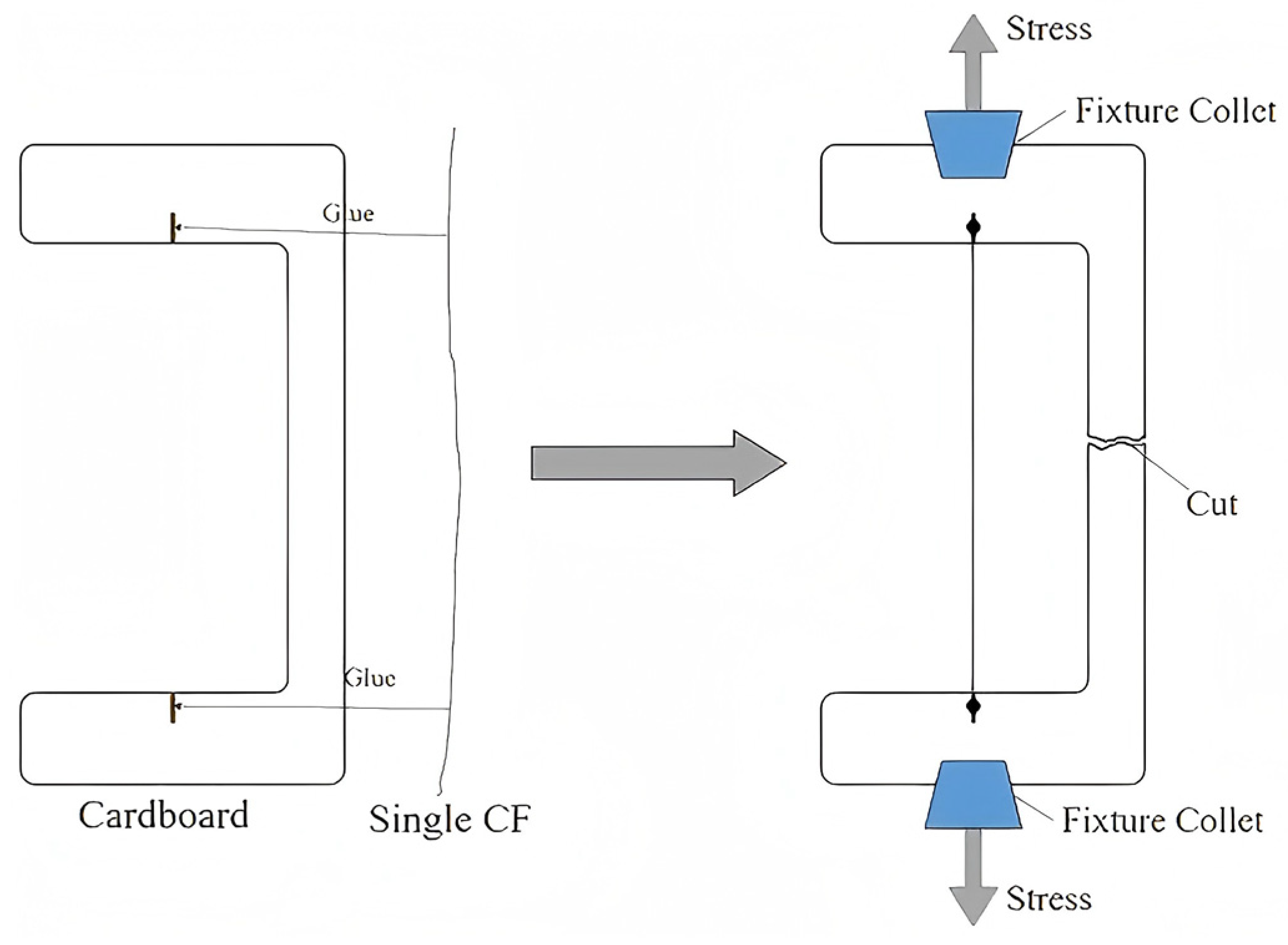
The surface morphology of the CNTs/CF reinforcement was observed using an SEM (SU-70, Hitachi Ltd. Tokyo, Japan) to investigate the growth status of CNTs on the CF surface under different process parameters. Prior to SEM characterization, the samples were sputter-coated with gold for 15 s to enhance their conductivity. The scanning voltage was set at 15 kV. The structural ordering on carbon fiber surfaces before and after EAO treatment, as well as under different CNT growth process conditions, was analyzed using Raman spectroscopy (LabRAM HR-800, HORIBA Jobin Yvon Co., Longjumeau, France). The spectra of CNTs/CF exhibit their characteristic D and G bands. The intensity ratio (D/G, denoted as R value) between the D peak (~1360 cm−1, representing defects in the graphite lattice) and the G peak (~1580 cm−1, corresponding to the ideal graphite lattice) serves as an indicator of the graphitization degree of the carbon material. A He-Ne laser with a wavelength of 633 nm was employed as the excitation source, and three measurement points were collected for each sample. The monofilament tensile strength was measured on an XQ-1C fiber tensile testing machine in accordance with the ASTM D3822-07 standard. Figure 3 shows a schematic diagram of the monofilament tensile strength test specimen preparation. CF monofilaments of specified length were cut and fixed onto test paper using strong adhesive, followed by natural air-drying and curing before testing with the fiber tensile strength tester. For each sample group, 40 filaments were tested, and the average value was calculated. The monofilament tensile strength was determined using Equation (1):
σ = 4 F π d 2
In this equation, σ represents the monofilament tensile strength (GPa), F denotes the tensile load applied to the filament (N), and d is the diameter of the carbon fiber monofilament (m).

3. Results and Discussion

3.1. Influence of Temperature on the Continuous Preparation of CNTs/CF

3.1.1. Morphological Properties

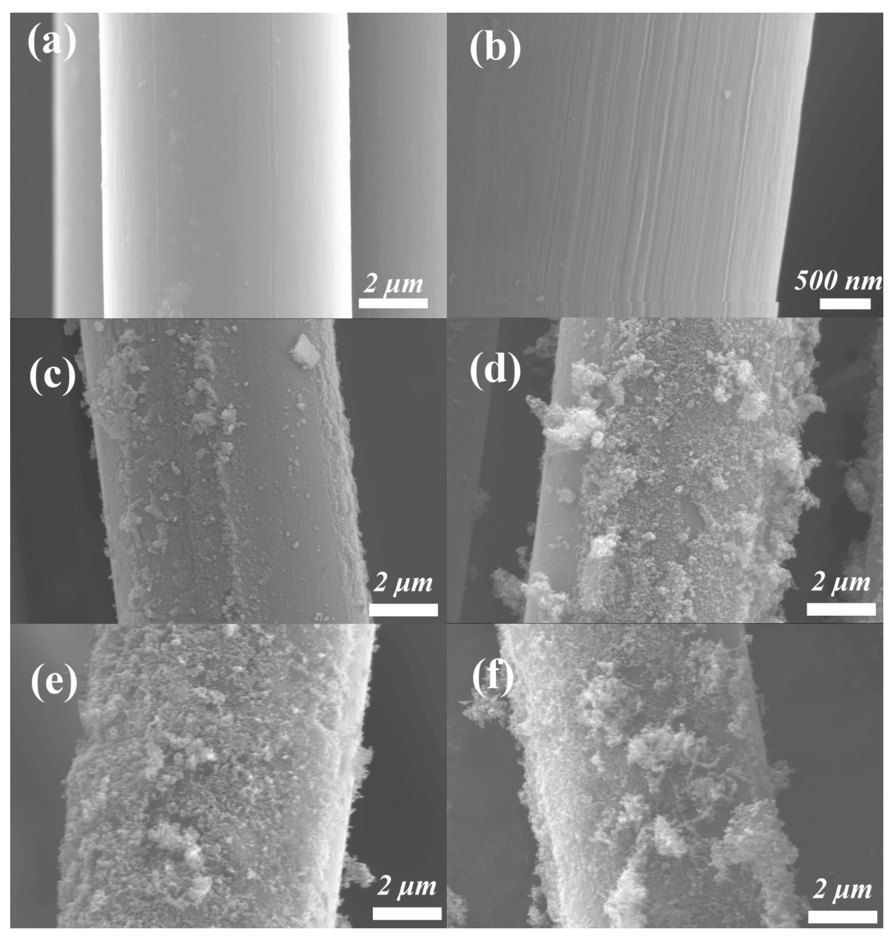
Figure 4 presents SEM images of desized CF, EAO CF, and CNTs/CF reinforcements prepared at different temperatures. Compared with the smooth surface of desized CF, the EAO CF exhibits elongated grooves formed by surface etching, which provides favorable conditions for the attachment of catalytic metal nanoparticles. CNTs/CF reinforcements are shown in the panels c-f of Figure 4. In Figure 4c, only sparse and underdeveloped CNTs are observed on the CF surface at 450 °C, making them barely detectable. When the temperature increases to 500 °C, thin and short CNTs grow on the fiber surface shown in Figure 4d, though their distribution remains non-uniform. At 550 °C (Figure 4e), the CF surface demonstrates significantly enhanced CNT growth—the nanotubes become more numerous and uniformly cover the fiber surface, indicating high catalytic activity and markedly accelerated CNT formation. However, with further temperature increase, excessive CNT growth occurs in Figure 4f, leading to aggregation phenomena where thick CNTs cluster into bundles.

3.1.2. Raman Measurements at Different Growth Temperatures

Figure 5 shows the Raman spectra of desized CF, EAO CF, and CNTs/CF reinforcements prepared at different temperatures, along with their corresponding R-values. The R-value in Raman spectroscopy is the intensity ratio of the D peak (reflecting lattice disorder) to the G peak (representing graphitic ordering), serving as a key quantitative indicator for structural defects and ordering in carbon materials. A lower R-value signifies higher graphitization degree and fewer defects. The R-value of the desized CF was 0.897. After EAO treatment, the R-value decreased to 0.839, indicating that the EAO treatment etched away some disordered carbon structures from the surface of the desized CF, thereby improving the surface structural ordering. With changes in growth temperature, the R-value first decreased and then increased. It can be observed that the R-values at 350 °C and 400 °C were almost identical and both relatively high, suggesting almost no CNT growth at these temperatures. As the temperature increased further, the R-value decreased, reaching its lowest value at 500 °C, where the graphitization degree was optimal. This indicates that the number of CNTs grown on the CF surface increased with temperature, and the graphitization degree also improved with rising temperature. At 550 °C and 600 °C, the R-values gradually increased again. The formation of CNTs can be explained as follows: After acetylene decomposes on the catalyst surface, the generated carbon atoms diffuse from the surface into the interior of the catalyst particles and ultimately reach the particle edges to participate in CNT nucleation and growth [30]. At lower temperatures, carbon diffusion through the catalyst and surface carbon impurity layer formation compete as dominant processes. Higher temperatures favor carbon diffusion, promoting CNT growth. However, when the temperature becomes excessively high, gas-phase reactions of acetylene intensify (e.g., dimerization to form C4H4). The resulting byproducts deposit as a carbon impurity layer, covering the catalyst’s active sites and causing catalyst deactivation, thus reducing CNT yield [31].

3.1.3. Test of Monofilament Tensile Strength at Different Growth Temperatures

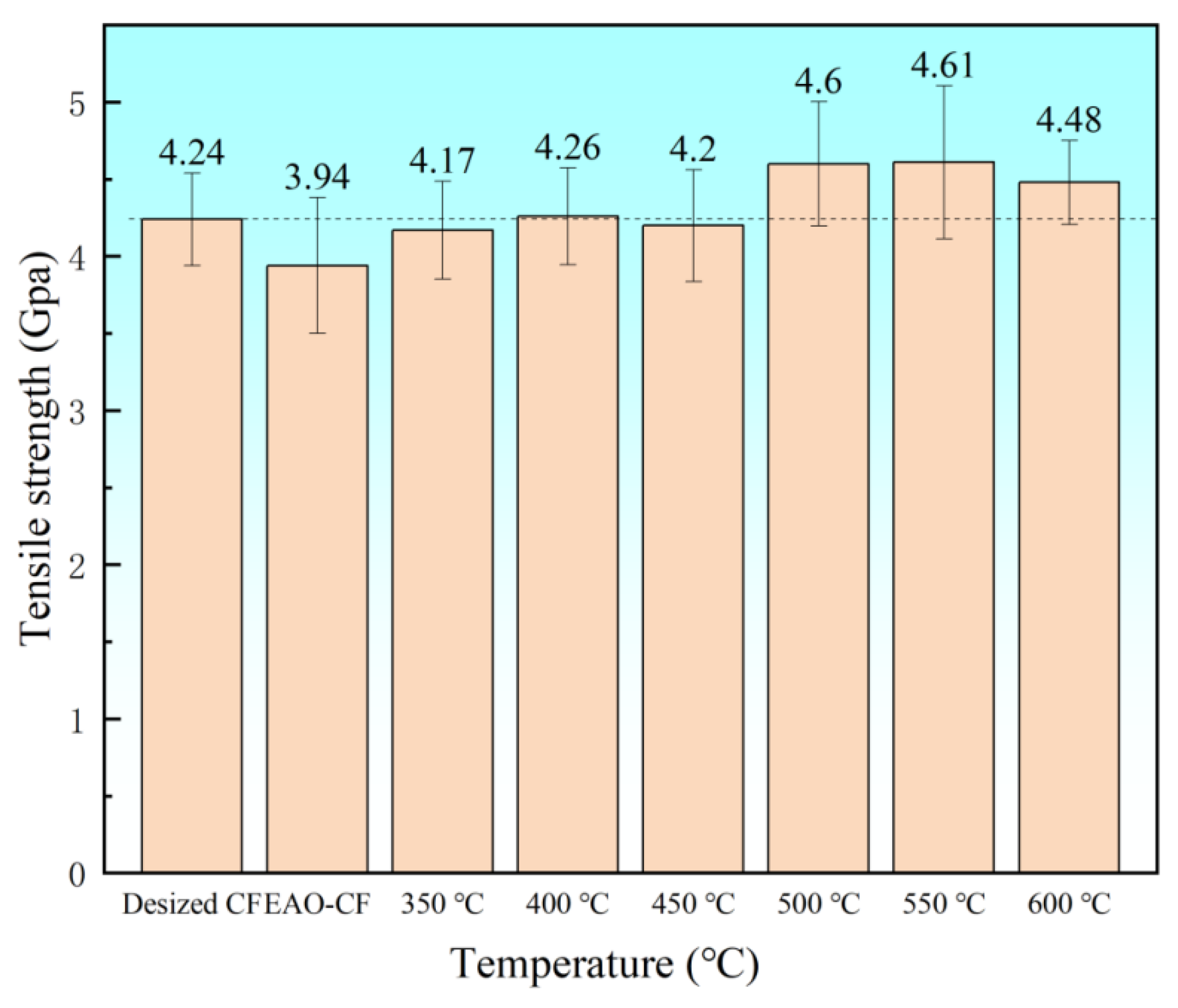
The monofilament tensile strength tests were conducted on CNTs/CF reinforcement samples prepared at different growth temperatures, with the results shown in Figure 6. It can be observed that the monofilament tensile strength of EAO CF significantly decreased. The monofilament tensile strength of CNTs/CF reinforcements grown at 350 °C, 400 °C, and 450 °C showed little variation, though all were higher than that of EAO CF. This indicates that CNTs generated during the CVD process can repair surface defects of CF, but at lower temperatures, insufficient catalyst activity and slow carbon source decomposition result in limited CNT growth, leading to minimal changes in the monofilament tensile strength of CNTs/CF reinforcements. At 500 °C and 550 °C, the monofilament tensile strength of the reinforcements increased significantly, reaching a maximum value of 4.61 ± 0.50 GPa (mean ± standard deviation, n = 40) at 550 °C, an 8.7% increase compared to desized CF (4.24 ± 0.30 GPa). This demonstrates that at this temperature, CNTs grew well on the CF surface, effectively enhancing the mechanical properties of the CF. When the temperature reached 600 °C, the monofilament tensile strength of CNTs/CF reinforcements decreased slightly. This is attributed to excessive temperature, which intensifies the etching effect of catalyst particles and H2 on the CF surface, leading to reduced tensile strength. Moreover, excessively high temperatures cause the carbon source gas to undergo side reactions and deposit carbon impurities, which can coat the surface of the catalyst, adversely affecting the growth of carbon nanotubes [31].

3.2. Influence of H2 Flow Rate on the Continuous Preparation of CNTs/CF

3.2.1. Raman Measurements at Different H2 Flow

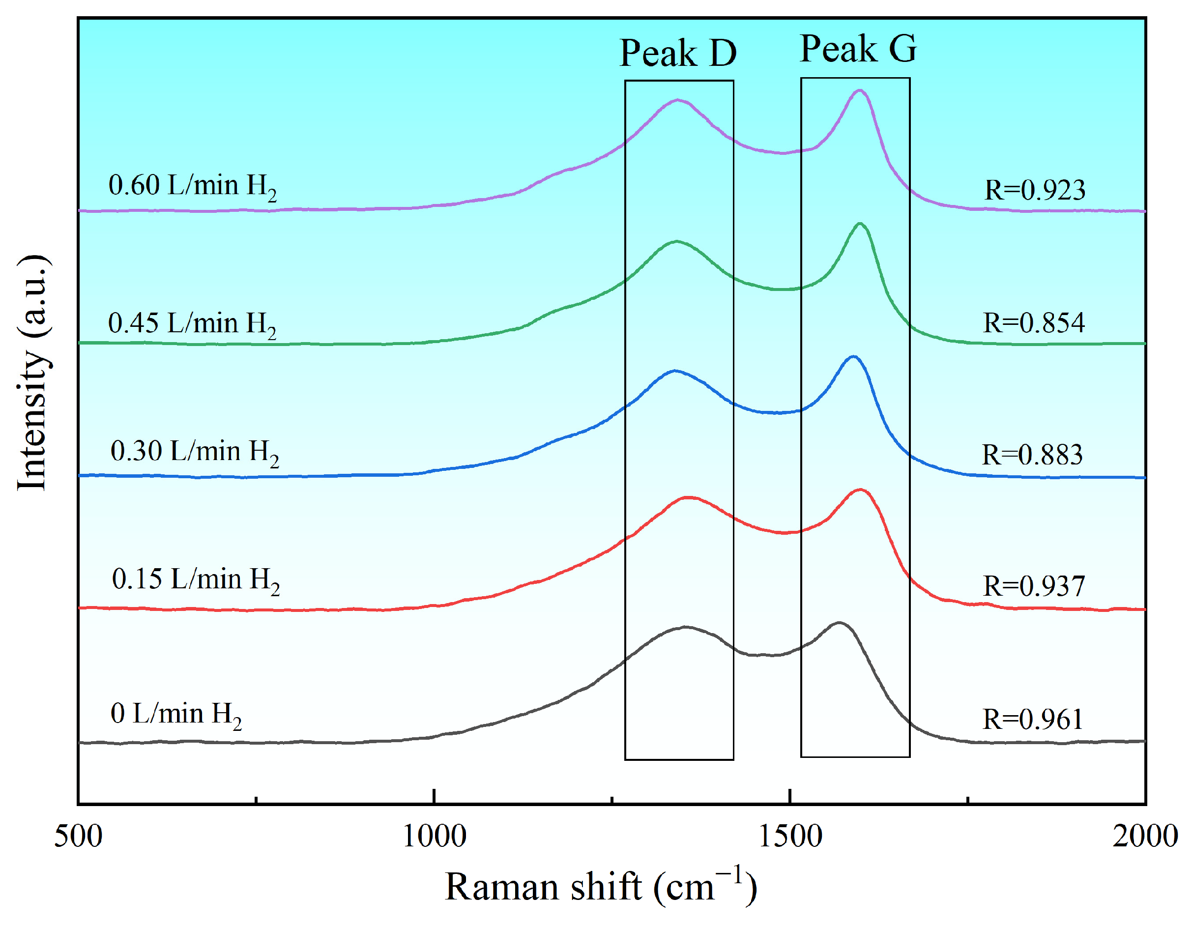
Figure 7 presents the Raman spectra and corresponding R-values of CNTs/CF reinforcements prepared under different hydrogen flow rates. When no H2 was introduced, the sample exhibited a high R-value, indicating insufficient reduction of the catalyst precursor, which hindered effective CNT growth. This resulted in substantial amorphous carbon deposition on the CF surface, leading to low structural ordering. As the hydrogen flow rate increased, the R-values progressively decreased. This demonstrates that higher H2 concentrations enhanced the reduction degree of catalyst precursors and improved catalytic efficiency, promoting abundant CNT growth on the carbon fiber surface and consequently strengthening surface graphitization. However, at a H2 flow rate of 0.6 L/min, the R-value showed a significant increase. Because excessive hydrogen flow rates induce catalytic hydrogenation of carbon (forming CH4) and etching of nanotubes, leading to reduced carbon yield, increased amorphous carbon deposits, and degraded crystallinity [32].

3.2.2. Test of Monofilament Tensile Strength at Different H2 Flow

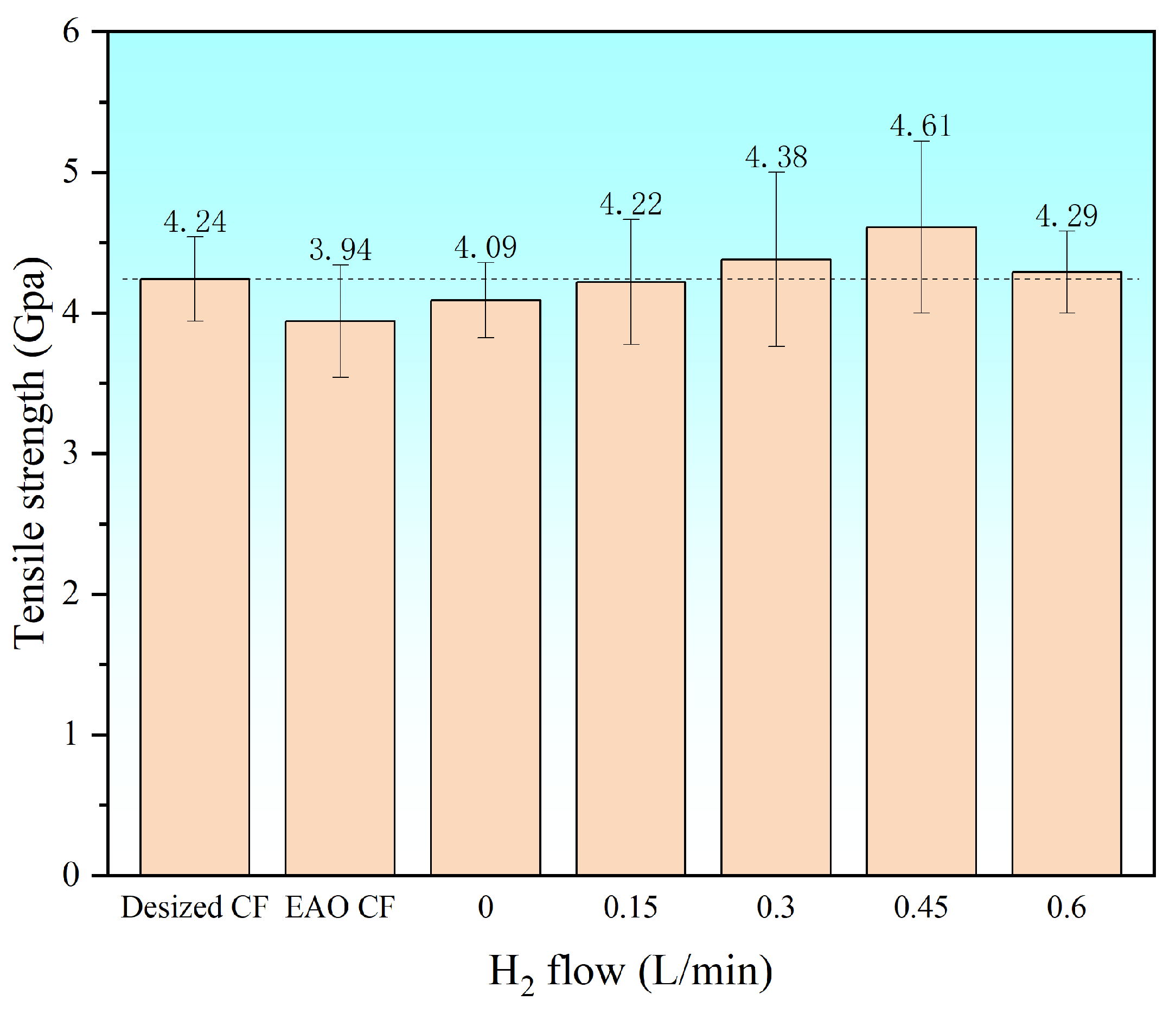
Figure 8 displays the monofilament tensile strength of samples prepared under different H2 flow rates. The results clearly demonstrate that as the H2 flow rate increases, the tensile strength of the CNTs/CF reinforcement continuously improves. This indicates that higher H2 flow rates lead to more complete reduction of the catalyst, resulting in greater CNT growth and consequently higher tensile strength of the obtained samples. The maximum tensile strength of 4.61 ± 0.61 GPa (mean ± standard deviation, n = 40) GPa (an 8.7% increase compared to desized CF) was achieved at a H2 flow rate of 0.45 L/min. However, when the H2 flow rate reached 0.6 L/min, the tensile strength decreased due to catalytic hydrogenation of carbon (forming CH4) and etching of nanotubes. This reduced the quantity of grown CNTs, thereby diminishing their reinforcing and surface-repairing effects on the CFs.

4. Conclusions

CVD process parameters significantly influence the growth characteristics of CNTs and the resulting mechanical properties of CNTs/CF composites. Through systematic investigation using a continuous process with Fe-Ni bimetallic catalyst, we established that an optimal balance between CVD temperature and hydrogen flow rate is crucial for achieving high-performance reinforcements. The experimental results reveal that 550 °C represents the optimal growth temperature, where the catalyst activity reaches its peak to promote dense CNT growth while maintaining good graphitization, resulting in a maximum tensile strength improvement of 8.7% compared to desized CF. Regarding the growth atmosphere, the hydrogen flow rate of 0.45 L/min with fixed C2H2 at 0.3 L/min produces composites with optimal graphitization and mechanical properties, while excessive hydrogen flow leads to reduced CNT growth efficiency. The developed continuous process proves particularly effective when combining the Fe-Ni catalyst system with these optimized parameters (550 °C, H2: C2H2 = 0.45 L/min: 0.3 L/min), yielding CNTs/CF reinforcements with superior CNT growth morphology and significantly enhanced mechanical performance. These findings provide important insights into the scalable production of high-quality CNT-reinforced composites through precise control of CVD conditions, establishing clear process–property relationships that can guide future optimization efforts in CF-reinforced composites development.

Author Contributions

Conceptualization, Y.Z. and Y.W.; formal analysis, Y.Z., S.X. and D.Z.; investigation, Y.Z., Z.X. and Y.Y.; methodology, Y.Z., Y.W. and J.Z.; validation, Y.Z., J.G. and Y.L.; writing—original draft, Y.Z.; writing—review and editing, Y.Z., Y.W. and J.Z. All authors have read and agreed to the published version of the manuscript.

Funding

The authors thank the editor and the anonymous reviewers for their valuable comments on this manuscript. This research was funded by Key R&D Program of Shandong Province, China (2025CXGC010407).

Data Availability Statement

Dataset available on request from the authors.

Conflicts of Interest

Author Jianwei Zhang was employed by the company Shandong North Modern Chemical Industry Co., Ltd. The remaining authors declare that the research was conducted in the absence of any commercial or financial relationships that could be construed as a potential conflicts of interest.

References

  1. Shi, L.; Song, G.; Li, P.; Li, X.; Pan, D.; Huang, Y.; Ma, L.; Guo, Z. Enhancing interfacial performance of epoxy resin composites via in-situ nucleophilic addition polymerization modification of carbon fibers with hyperbranched polyimidazole. Compos. Sci. Technol. 2021, 201, 108522. [Google Scholar] [CrossRef]
  2. Wu, D.; Yao, Z.; Sun, X.; Liu, X.; Liu, L.; Zhang, R.; Wang, C. Mussel-tailored carbon fiber/carbon nanotubes interface for elevated interfacial properties of carbon fiber/epoxy composites. Chem. Eng. J. 2022, 429, 132449. [Google Scholar] [CrossRef]
  3. Zheng, H.; Zhang, W.; Li, B.; Zhu, J.; Wang, C.; Song, G.; Wu, G.; Yang, X.; Huang, Y.; Ma, L. Recent advances of interphases in carbon fiber-reinforced polymer composites: A review. Compos. Part B Eng. 2022, 233, 109639. [Google Scholar] [CrossRef]
  4. He, M.; Xu, P.; Zhang, Y.; Liu, K.; Yang, X. Phthalocyanine nanowires@GO/carbon fiber composites with enhanced interfacial properties and electromagnetic interference shielding performance. Chem. Eng. J. 2020, 388, 124255. [Google Scholar] [CrossRef]
  5. Ma, L.; Zhu, Y.; Feng, P.; Song, G.; Huang, Y.; Liu, H.; Zhang, J.; Fan, J.; Hou, H.; Guo, Z. Reinforcing carbon fiber epoxy composites with triazine derivatives functionalized graphene oxide modified sizing agent. Compos. Part B Eng. 2019, 176, 107078. [Google Scholar] [CrossRef]
  6. Zhao, M.; Meng, L.; Ma, L.; Ma, L.; Yang, X.; Huang, Y.; Ryu, J.E.; Shankar, A.; Li, T.; Yan, C.; et al. Layer-by-layer grafting CNTs onto carbon fibers surface for enhancing the interfacial properties of epoxy resin composites. Compos. Sci. Technol. 2018, 154, 28–36. [Google Scholar] [CrossRef]
  7. Lee, S.-B.; Choi, O.; Lee, W.; Yi, J.-W.; Kim, B.-S.; Byun, J.-H.; Yoon, M.-K.; Fong, H.; Thostenson, E.T.; Chou, T.-W. Processing and characterization of multi-scale hybrid composites reinforced with nanoscale carbon reinforcements and carbon fibers. Compos. Part A Appl. Sci. Manuf. 2011, 42, 337–344. [Google Scholar] [CrossRef]
  8. Yang, X.; Zhang, Y.; Liu, J.; Huang, J.; Ji, J.; Wang, T.; Li, T. Enhancing Mechanical Properties of CF/Al Composites through Multi-scale Interfacial Strengthening by Introducing Carbon Nanotube-grafted Carbon Fibers. Surf. Interfaces 2025, 64, 106440. [Google Scholar] [CrossRef]
  9. Quan, G.; Wu, Y.; Li, W.; Li, D.; Liu, X.; Wang, K.; Dai, S.; Xiao, L.; Ao, Y. Construction of cellulose nanofiber/carbon nanotube synergistic network on carbon fiber surface to enhance mechanical properties and thermal conductivity of composites. Compos. Sci. Technol. 2024, 248, 110454. [Google Scholar] [CrossRef]
  10. Jourdain, V.; Bichara, C. Current understanding of the growth of carbon nanotubes in catalytic chemical vapour deposition. Carbon 2013, 58, 2–39. [Google Scholar] [CrossRef]
  11. Mathur, R.B.; Chatterjee, S.; Singh, B.P. Growth of carbon nanotubes on carbon fibre substrates to produce hybrid/phenolic composites with improved mechanical properties. Compos. Sci. Technol. 2008, 68, 1608–1615. [Google Scholar] [CrossRef]
  12. Tomie, T.; Inoue, S.; Kohno, M.; Matsumura, Y. Prospective growth region for chemical vapor deposition synthesis of carbon nanotube on C-H-O ternary diagram. Diam. Relat. Mater. 2010, 19, 1401–1404. [Google Scholar] [CrossRef]
  13. Zheng, L.; Wang, Y.; Qin, J.; Wang, X.; Lu, R.; Qu, C.; Wang, C. Scalable manufacturing of carbon nanotubes on continuous carbon fibers surface from chemical vapor deposition. Vacuum 2018, 152, 84–90. [Google Scholar] [CrossRef]
  14. De Greef, N.; Zhang, L.; Magrez, A.; Forro, L.; Locquet, J.-P.; Verpoest, I.; Seo, J.W. Direct growth of carbon nanotubes on carbon fibers: Effect of the CVD parameters on the degradation of mechanical properties of carbon fibers. Diam. Relat. Mater. 2015, 51, 39–48. [Google Scholar] [CrossRef]
  15. Kim, K.J.; Yu, W.-R.; Youk, J.H.; Lee, J. Degradation and Healing Mechanisms of Carbon Fibers during the Catalytic Growth of Carbon Nanotubes on Their Surfaces. ACS Appl. Mater. Interfaces 2012, 4, 2250–2258. [Google Scholar] [CrossRef] [PubMed]
  16. Qin, J.; Wang, C.; Yao, Z.; Ma, Z.; Cui, X.; Gao, Q.; Wang, Y.; Wang, Q.; Wei, H. Mechanical property deterioration and defect repair factors of carbon fibers during the continuous growth of carbon nanotubes by chemical vapor deposition. Ceram. Int. 2021, 47, 19213–19219. [Google Scholar] [CrossRef]
  17. Zhang, Q.; Liu, J.; Sager, R.; Dai, L.; Baur, J. Hierarchical composites of carbon nanotubes on carbon fiber: Influence of growth condition on fiber tensile properties. Compos. Sci. Technol. 2009, 69, 594–601. [Google Scholar] [CrossRef]
  18. Liu, L.; Jia, C.; He, J.; Zhao, F.; Fan, D.; Xing, L.; Wang, M.; Wang, F.; Jiang, Z.; Huang, Y. Interfacial characterization, control and modification of carbon fiber reinforced polymer composites. Compos. Sci. Technol. 2015, 121, 56–72. [Google Scholar] [CrossRef]
  19. Khavrus, V.O.; Lemesh, N.V.; Gordijchuk, S.V.; Tripolsky, A.I.; Ivashchenko, T.S.; Biliy, M.M.; Strizhak, P.E. Chemical catalytic vapor deposition (CCVD) synthesis of carbon nanotubes by decomposition of ethylene on metal (Ni, Co, Fe) nanoparticles. React. Kinet. Catal. Lett. 2008, 93, 295–303. [Google Scholar] [CrossRef]
  20. Cui, B.; Wang, C.; Wang, Y.; Wang, C.; Jiang, H.; Li, M.; Xu, Z. In-situ growth of bamboo-like carbon nanotubes from Cu catalyst on continuous carbon fibre for interfacial enhancement. Compos. Sci. Technol. 2023, 234, 109933. [Google Scholar] [CrossRef]
  21. Chen, Y.; Ciuparu, D.; Lim, S.Y.; Yang, Y.H.; Haller, G.L.; Pfefferle, L. Synthesis of uniform diameter single-wall carbon nanotubes in Co-MCM-41: Effects of the catalyst prereduction and nanotube growth temperatures. J. Catal. 2004, 225, 453–465. [Google Scholar] [CrossRef]
  22. Saputri, D.D.; Jan’ah, A.M.; Saraswati, T.E. Synthesis of Carbon Nanotubes (CNT) by Chemical Vapor Deposition (CVD) Using a Biogas-Based Carbon Precursor: A Review, Proceedings of the 15th Joint Conference on Chemistry (JCC), Salatiga, Indonesia, 9 September 2020; IOP Publishing: Bristol, UK, 2020. [Google Scholar]
  23. Chiang, W.-H.; Sakr, M.; Gao, X.P.A.; Sankaran, R.M. Nanoengineering NixFe1−x Catalysts for Gas-Phase, Selective Synthesis of Semiconducting Single-Walled Carbon Nanotubes. ACS Nano 2009, 3, 4023–4032. [Google Scholar] [CrossRef] [PubMed]
  24. Ahmad, S.; Liao, Y.; Hussain, A.; Zhang, Q.; Ding, E.-X.; Jiang, H.; Kauppinen, E.I. Systematic investigation of the catalyst composition effects on single-walled carbon nanotubes synthesis in floating-catalyst CVD. Carbon 2019, 149, 318–327. [Google Scholar] [CrossRef]
  25. Cui, B.; Wang, C.; Wang, Y.; Wang, C.; Jiang, H.; Li, M.; Tan, H.; Xu, Z. One-step scheme in continuous carbon nanofilament-carbon fiber multi-scale reinforcement fabrication at ultra-low temperature with simultaneous tensile and interfacial improvement. Chem. Eng. J. 2023, 478, 147447. [Google Scholar] [CrossRef]
  26. Lee, G.; Youk, J.H.; Lee, J.; Sul, I.H.; Yu, W.-R. Low-temperature grafting of carbon nanotubes on carbon fibers using a bimetallic floating catalyst. Diam. Relat. Mater. 2016, 68, 118–126. [Google Scholar] [CrossRef]
  27. Yao, Z.; Wang, C.; Qin, J.; Su, S.; Wang, Y.; Wang, Q.; Yu, M.; Wei, H. Interfacial improvement of carbon fiber/epoxy composites using one-step method for grafting carbon nanotubes on the fibers at ultra-low temperatures. Carbon 2020, 164, 133–142. [Google Scholar] [CrossRef]
  28. Shi, P.; Zhu, Y.; Yan, C.; Liu, D.; Xu, H. Electrochemically oxidized carbon fiber surfaces: Mechanism-driven models for enhanced surface engineering. Mater. Today Chem. 2025, 46, 102708. [Google Scholar] [CrossRef]
  29. Huang, C.; Zhang, P.; Liu, Z.; Sun, M.; Liu, H.; Sun, J.; Li, B.; Zhao, Y.; Bao, J. Effect of electrochemical anodic oxidation modification on the interfacial properties of carbon fiber reinforced polyimide composites. Polym. Compos. 2025, 46, 2390–2403. [Google Scholar] [CrossRef]
  30. Gakis, G.P.; Termine, S.; Trompeta, A.-F.A.; Aviziotis, I.G.; Charitidis, C.A. Unraveling the mechanisms of carbon nanotube growth by chemical vapor deposition. Chem. Eng. J. 2022, 445, 136807. [Google Scholar] [CrossRef]
  31. Puretzky, A.A.; Geohegan, D.B.; Jesse, S.; Ivanov, I.N.; Eres, G. In situ measurements and modeling of carbon nanotube array growth kinetics during chemical vapor deposition. Appl. Phys. A Mater. Sci. Process. 2005, 81, 223–240. [Google Scholar] [CrossRef]
  32. Ma, Y.; Dichiara, A.B.; He, D.; Zimmer, L.; Bai, J. Control of product nature and morphology by adjusting the hydrogen content in a continuous chemical vapor deposition process for carbon nanotube synthesis. Carbon 2016, 107, 171–179. [Google Scholar] [CrossRef]
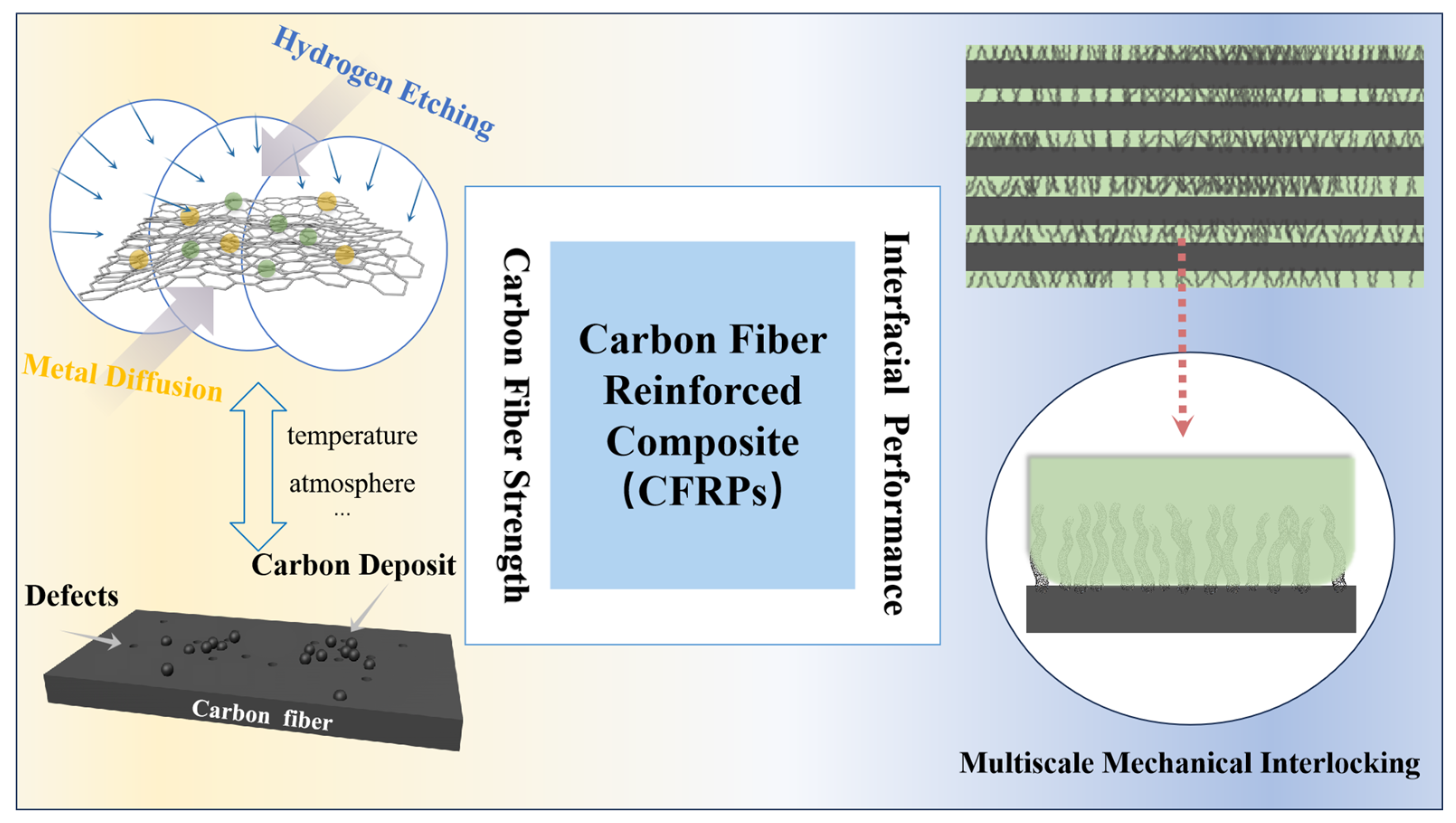
Figure 1. Illustration of the critical factors that determine the mechanical performance of CFRPs.
Surfaces 08 00060 g001
Figure 2. Diagram of continuous CNTs/CF production line: 1—Wire feeder; 2, 6, 9, 13—Fiber transfer and tension control components; 3—Electrochemical anodizing tank; 4—Cleaning tank; 5, 8—Drying equipment; 7—Catalyst precursor impregnation tank; 10—Gas-sealed device; 11—Catalyst particle reduction furnace; 12—CNT in situ growth furnace; 14—Winder.
Surfaces 08 00060 g002
Figure 3. Monofilament tensile test specimen.
Surfaces 08 00060 g003
Figure 4. SEM of CNTs/CF prepared at different growth temperatures. (a) Desized CF. (b) EAO CF. (c) 450 °C. (d) 500 °C. (e) 550 °C. (f) 600 °C.
Surfaces 08 00060 g004
Figure 5. Raman spectra of CNTs/CF prepared at different growth temperatures.
Surfaces 08 00060 g005
Figure 6. Tensile strength of CF monofilament prepared at different growth temperature.
Surfaces 08 00060 g006
Figure 7. Raman spectra of CNTs/CF prepared at different H2 flow.
Surfaces 08 00060 g007
Figure 8. Tensile strength of CF monofilament prepared at different H2 flow.
Surfaces 08 00060 g008
Disclaimer/Publisher’s Note: The statements, opinions and data contained in all publications are solely those of the individual author(s) and contributor(s) and not of MDPI and/or the editor(s). MDPI and/or the editor(s) disclaim responsibility for any injury to people or property resulting from any ideas, methods, instructions or products referred to in the content.