Article

Drying and Film Formation Processes of Graphene Oxide Suspension on Nonwoven Fibrous Membranes with Varying Wettability

1
School of Energy and Power Engineering, Dalian University of Technology, Dalian 116024, China
2
Guangdong Provincial Key Laboratory of Green Chemical Product Technology, School of Chemistry and Chemical Engineering, South China University of Technology, Guangzhou 510640, China
*
Author to whom correspondence should be addressed.
Surfaces 2025, 8(2), 39; https://doi.org/10.3390/surfaces8020039
Submission received: 26 May 2025 / Revised: 15 June 2025 / Accepted: 16 June 2025 / Published: 18 June 2025
(This article belongs to the Special Issue Surface Engineering of Thin Films)

Abstract

:
Graphene oxide (GO) films have attracted significant attention due to their potential in separation and filtration applications. Based on their unique lamellar structure and ultrathin nature, GO films are difficult to maintain in a free-standing form and typically require substrate support. Consequently, understanding their film formation behavior and mechanisms on substrates is of paramount importance. This work employs commonly used nonwoven fibrous membranes as substrates and guided by the coffee-ring theory, systematically investigates the film formation behaviors, film morphology, and underlying mechanisms of GO films on fibrous membranes with varying wettability. Fibrous membranes with different wetting properties—hydrophilic, hydrophobic, and superhydrophobic—were prepared via electrospinning and initiated chemical vapor deposition (iCVD) surface modification techniques. The spreading behaviors, deposition dynamics, capillary effects, and evaporation-induced film formation mechanisms of GO suspensions on these substrates were thoroughly examined. The results showed that GO formed belt-like, ring-like, and circular patterns on the three fibrous membranes, respectively. GO films encapsulated more than the upper half, approximately the upper half, and the top portion of fibers, respectively. Pronounced wrinkling of GO films was observed except for those on the hydrophilic fibrous membrane. This work demonstrates that tuning the wettability of fibrous substrates enables precise control over GO film morphology, including fiber encapsulation, wrinkling, and coverage area. Furthermore, it deepens the understanding of the interactions between 1D nanofibers and 2D GO sheets at low-dimensional scales, laying a foundational basis for the optimized design of membrane engineering.

Graphical Abstract

1. Introduction

The evaporation of particle-containing solutions often results in ring-like deposition patterns. This phenomenon, commonly known as the “coffee-ring effect”, is caused by capillary flows during the drying process [1]. Graphene oxide (GO) has attracted significant attention owing to its unique mechanical properties [2], high specific surface area [3], corrosion resistance [4], electrical conductivity [5], optical properties [6], thermal conductivity [7], and reducibility into reduced GO (rGO) [8,9]. Unlike spherical particles, GO possesses a unique two-dimensional sheet-like structure. Therefore, the evaporation behavior of GO suspensions is worth studying. He et al. demonstrated that depending on the surface chemistry and wettability of the substrate, GO can form various deposition patterns, including the coffee-ring [10].
Due to their unique layer structure [11] and the existence of oxygen-containing functional groups [12], GO films have been widely used for the separation of substances such as dyes [13,14], salts [13,15,16], and gas [17,18]. However, since these processes are often accompanied by pressure, GO films are usually supported by porous substrates to enhance their mechanical stability [17,19]. GO film preparation methods can be broadly classified into two categories: (1) pressure-assisted techniques, such as vacuum filtration [20,21], and pressure-driven filtration [22,23]; and (2) evaporation-induced assembly methods, such as spray coating [19], drop casting [24], dip coating [25], and layer-by-layer (LBL) assembly [26]. Filtration-based techniques often involve applied pressure, which may affect film morphology and structure. Evaporation-driven self-assembly methods have gained widespread attention due to their simplicity and time efficiency [27]. Among them, the drop-casting method is particularly attractive because it is easy to operate [28]. It requires no specialized equipment, only a fixed volume and concentration of GO suspension deposited on the substrate, followed by evaporation. Because no external force is involved in this process, film formation is solely governed by the properties of the suspension and the substrate. Different mechanisms of film formation can lead to various film morphologies [29], which may further influence the separation and filtration performance [30]. Therefore, understanding the evaporation behavior of GO on porous substrates is important.
GO film formation on porous anodic aluminum oxide (AAO) membranes has been investigated. Kim et al. found that the pores in AAO suppressed capillary flow and consequently inhibited the coffee-ring effect [31]. The AAO membrane provides well-defined and uniform pores. However, it breaks easily and is relatively expensive [32]. To fully utilize GO films, porous substrates with higher mechanical strength are necessary.
The electrospun fibrous membranes exhibit high porosity, large specific surface area, and highly interconnected pore structures [33,34], offering excellent permeability and separation performance [35,36]. Moreover, they have good mechanical strength [37]. Furthermore, by tuning the electrospinning conditions—such as polymer concentration, spinning time, and receiving area—the fiber diameter, membrane area, and thickness can be precisely controlled. Surface modification can also be performed to modify the wettability. These features make them promising substrate candidates for GO films; GO films on electrospun fibrous membranes have already been applied in nanofiltration [13,16], forward osmosis (FO) [38], and pervaporation [39]. Moreover, the study of GO films on fibrous membranes could provide significant insights into the interfacial integration of 1D and 2D materials at low-dimensional scales. Due to the nanoscale fiber diameter, the fibers can be considered one-dimensional (1D) materials, while GO sheets, with their atomic-scale thickness, can be considered as two-dimensional (2D) materials [40].
In this work, fibrous membranes with identical fiber diameters but varying surface wettability (hydrophilic, hydrophobic, and superhydrophobic) were fabricated and used as substrates. The spreading behaviors and mechanisms of evaporation-induced GO film formation on fibrous membranes with varying wettability were investigated.

2. Materials and Methods

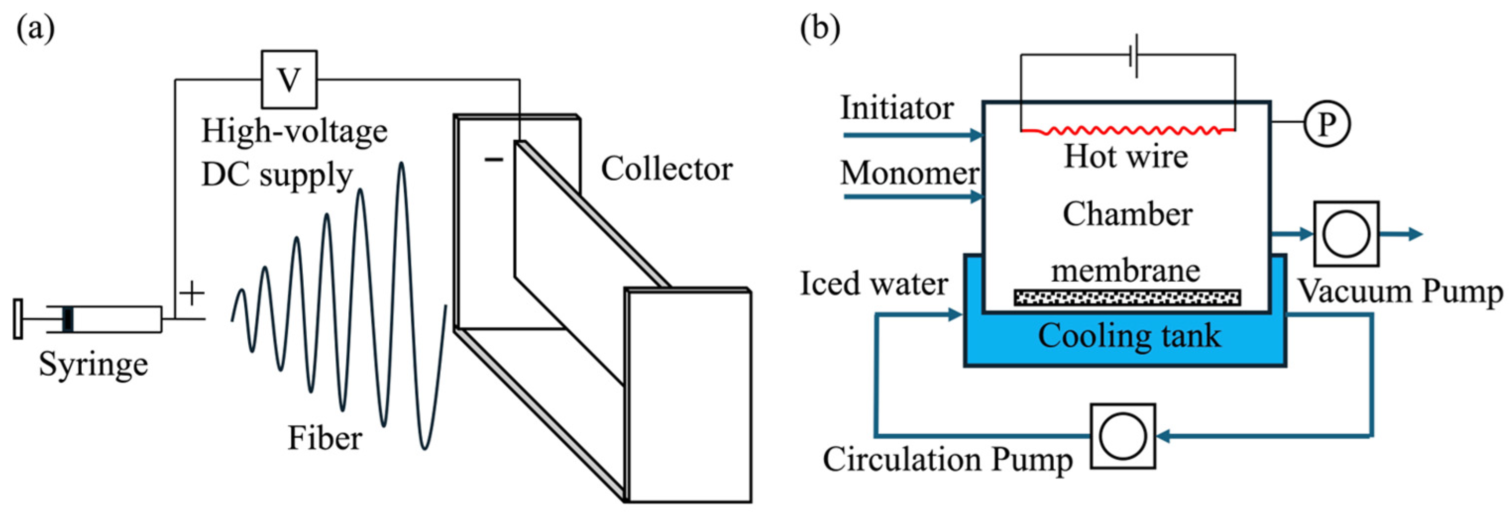
2.1. Electrospinning

As shown in Figure 1a, fibrous membranes were fabricated by electrospinning. Polyacrylonitrile (PAN) (DOW Inc., Midland, MI, USA) and polyvinylidene fluoride (PVDF) (Arkema, Paris, France) solutions were prepared with N,N-dimethylformamide (DMF) (Shanghai Aladdin Bio-Chem Technology Co., Ltd., Shanghai, China, AR > 99.5%) and acetone (Tianjin Kemiou Chemical Reagent Co., Ltd., Tianjin, China, AR > 99.5%) as solvents (95/5, wt./wt.). A PAN solution of 13 wt% and PVDF solution of 16 wt% concentration were selected for the membrane preparation. A magnetic stirrer was used to heat and stir the solutions in a 60 °C water bath for more than 6 h. Then, the solutions were cooled down to 25 °C. A plate was used to collect fibers. The environmental temperature of electrospinning was 25 °C. The humidity was 20%. The positive and negative voltage was 15 kV and 4 kV, respectively. The distance between the plate and jet was 20 cm. The flow rate was 0.015 mL/min. The fibrous membranes were placed in a fume hood for one day to desiccate. The parameters of electrospinning are shown in Table 1.

2.2. Surface Fluorination Treatment

As shown in Figure 1b, the surface fluorination treatment was carried out in a custom-built initiated chemical vapor deposition (iCVD) reactor (280 mm × 180 mm × 65 mm). The fibrous membrane was placed on the bottom plate (240 mm × 140 mm) of the reaction chamber. The filaments (80% Ni and 20% Cr) were placed 42 mm away from the bottom plate. A DC power supply was used to heat the filaments. A cooling water circulation system was set up under the bottom plate. Two thermocouple thermometers were used to measure the temperature of the filaments and the bottom plate, respectively. The temperatures were controlled at 220 ± 5 °C and 30 ± 5 °C, respectively. A mechanical pump (2XZ-44, Linhai Tan Vacuum Equipment Co., Ltd., Linhai, China) was applied to maintain the pressure inside the reaction chamber at 2800 ± 100 Pa. A pressure sensor (CYYZ11-HK-67-RS-16-B-G, Beijing Star Sensor Technology Co., Ltd., Beijing, China) connected to the computer was used to measure the pressure. A mass rotor flowmeter (LZB-3WB Changzhou Chengfeng Flowmeter Co., Ltd., Changzhou, China) was used to control the flow rate of the t-butyl peroxide initiator (Shanghai Aladdin Bio-Chem Technology Co., Ltd., Shanghai, China), which was maintained at 1 ± 0.1 mL/min. The perfluorodecanoic acid (PFDA) monomer (Sigma-Aldrich Co. LLC., St. Louis, MO, USA) was heated and vaporized in a water bath and then delivered into the reaction chamber through a steel capillary tube. An electric heating wire was wrapped around the tube to avoid condensation. The coating time was 60 min.

2.3. Contact Angle

The contact angle measurement was conducted to confirm the wettability of the membrane. The membrane was placed on the angle-measuring equipment (360A, Chengde Yike Experimental Instrument Co., Ltd., Chengde, China). Either 2.5 μL of DI water or a 1 mg/mL GO suspension (Shandong LeaderNano Tech Co., Ltd., Linyi, China) was drop-cast onto the membrane. Photographs of the droplets were taken, and the contact angles were measured. The test was repeated five times. The average value of the results was used as the contact angle of the membrane. The measured value corresponded to the apparent contact angle of the membrane, which was typically greater than the intrinsic contact angle of the membrane material. For the fibrous membrane, the intrinsic contact angle can be estimated using the Cassie–Baxter equation:
c o s θ * = r s c o s θ 1 + 1 s c o s θ 2
where θ* is the contact angle of the membrane, ∅s is the areal fraction of the air–liquid interface in contact with the fibrous membrane, and θ1 and θ2 are the intrinsic contact angle of the material and the air (θ2 = 180°), respectively. r is the roughness of the wet area. According to the previous study, the average pore size is approximately four times the fiber diameter [41]. Therefore, ∅ can be estimated using the following equation:
1 D D + S 2 0.36
where D and S are the fiber diameter and the spacing between adjacent fibers, respectively.
For the fibrous membrane, r can be estimated using the following equation:
r = L C = π 180 360 ° 2 θ 1 2 sin 360 ° 2 θ 1
where L and C are the actual wetted area and the projected area of the wetted region, respectively.

2.4. GO Film Preparation

2.4.1. Spreading Behaviors of GO Droplets on Fibrous Membranes with Varying Wettability

To better understand the mechanisms of GO film formation, the spreading behavior of GO droplets on fibrous membranes with varying wettability was investigated. Fibrous membranes were first cleaned with ethanol (Tianjin Fuyu Fine Chemical Co., Ltd., Tianjin, China) and then dried in an oven (Shanghai Lichen Instrument Technology Co., Ltd., Shanghai, China) at 60 °C for 1 h. GO suspension was carefully dropped onto each membrane using a micropipette (Dragon Laboratory Instruments Co., Ltd., Beijing, China) via a drop-casting method and manually spread. All spreading experiments were performed under ambient conditions (25 °C, ~40% relative humidity). The spreading behavior of the GO suspension was observed and recorded from the top view using a digital camera.
The movement of a droplet on the fibrous membrane is governed by its advancing contact angle θ*adv and receding contact angle θ*rec. When the droplet is spread, its front contact angle θ*front will increase. When θ*front exceeds θ*adv, the front edge of the droplet moves forward. Similarly, the rear contact angle θ*rear will decrease. When θ*rear falls below θ*rec, the rear edge recedes. The droplet can be successfully spread if the rear edge is pinned, which means θ*rec should be sufficiently small.
θ*rec on a porous interface can be estimated using the following equation:
c o s θ r e c * = r d , r e c c o s θ 1 + 1 d , r e c c o s θ 2
where ∅d,rec is a differential parameter, which depends on the fibrous membrane structure and can be represented by ∅s. In this work, all fibrous membranes had a nonwoven structure. According to the previous study [42], they could be considered as an inverse hoodoo structure. For the fibrous membrane with a relatively low intrinsic contact angle, a thin liquid film tends to remain between the fibers during droplet receding, resulting in θ2 being taken as the intrinsic contact angle of the water (θ2 = 0°). In this case, ∅d,rec can be calculated using the following equation:
d , r e c = 1 1 s
In contrast, for membranes with relatively high intrinsic contact angles, the droplet tends to detach rapidly from the fiber during receding. In this case, ∅d,rec can be calculated using the following equation:
d , r e c = 1

2.4.2. GO Film Preparation on Fibrous Membranes with Varying Wettability

As mentioned in Section 2.4.1, the fibrous membranes were first cleaned and dried. Each membrane was then mounted onto a glass tube with an approximate diameter of 15 mm to define the casting area. A 640 μL GO suspension was deposited onto the membrane surface using a micropipette via the drop-casting method. The droplet was manually spread to ensure uniform coverage across the membrane. All experiments were conducted under ambient conditions. The droplet and the resulting evaporated GO film were observed and recorded from a top-view perspective using a digital camera. The thickness of the dried GO film was estimated using the following equation:
h = c V A ρ
where h is the thickness of the film, c is the concentration of the GO suspension, V is the volume of the suspension, A is the spreading area, and ρ is the density of GO, which is typically taken as 1.8 g/cm3 [43]. Scanning electron microscopy (SEM) (Quanta 450, FEI Company, Hillsboro, OR, USA) was employed to characterize the microstructure of GO films. Prior to imaging, a thin layer of gold was deposited on the samples using a sputter coater (Polaron Q150T, Quorum Technologies Ltd., Lewes, UK) for 90 s to enhance imaging quality.

3. Results and Discussion

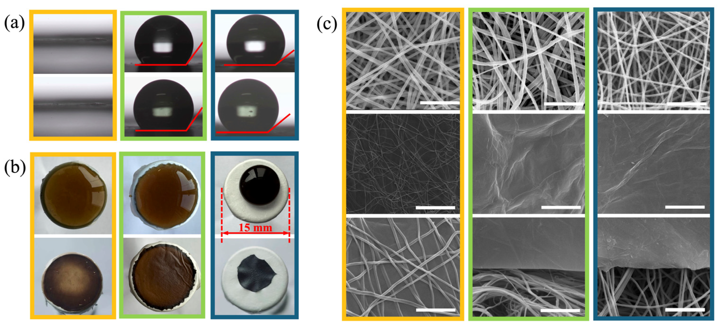
3.1. Preparation of Fibrous Membranes and GO Films

As shown in Figure 2, PAN and PVDF fibrous membranes were successfully fabricated via electrospinning, with an average fiber diameter of approximately 300 nm. To enhance hydrophobicity, a section of the PAN membrane was subjected to a surface fluorination treatment. As shown in Figure 2c, the change in fiber diameter after the treatment was negligible. The fiber diameters of fibrous membranes are summarized in Table 2.
For the PAN membrane, the droplet rapidly penetrated the membrane, leaving an insufficient volume on the membrane for contact angle measurement and demonstrating a hydrophilic membrane. The PVDF membrane had contact angles of 120°–144° for DI water and 129°–143° for GO suspension, demonstrating a hydrophobic membrane. The surface-fluorinated PAN membrane had contact angles of 152°–157° for DI water and 151°–154° for GO suspension, demonstrating a superhydrophobic membrane. No significant difference in contact angle was observed between DI water and GO suspension in any of the membranes. The wettability of fibrous membranes is summarized in Table 3.

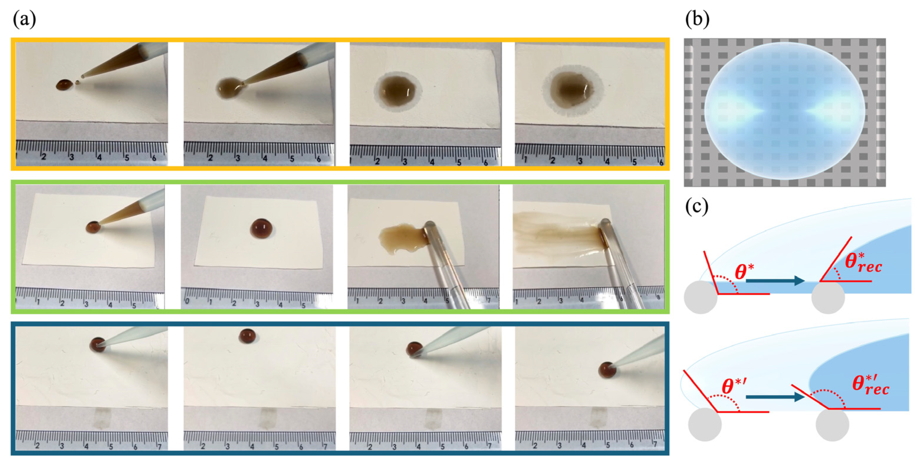
3.2. Spreading Behaviors of GO Droplets on Fibrous Membranes with Varying Wettability

The spreading behaviors of GO droplets on fibrous membranes with varying wettability are shown in Figure 3. The droplet partially penetrated the hydrophilic fibrous membrane, similar to the behavior of DI water in the previous study [44]. The lateral size of GO sheets was measured using a Zetasizer Nano ZS (Malvern Instruments, Malvern, UK). The sizes ranged from 3600 to 5600 nm, with a relatively narrow distribution centered around 4800 nm. As mentioned above, a fiber diameter of 300 nm corresponded to an estimated pore size of 1400 nm. This suggested that the fibrous membrane acted as a filter, allowing the penetration of GO sheets with relatively small lateral sizes.
On the hydrophobic fibrous membrane, the droplet could be spread into a defined area. On the superhydrophobic fibrous membrane, the droplet remained spherical and rolled on the surface without spreading. As mentioned above, these two distinct behaviors were attributed to different receding contact angles.
To estimate the receding contact angles, the intrinsic contact angles of the hydrophobic and superhydrophobic fibrous membranes θ,h and θ,s were calculated to be 98.84° and 126.11° using Equations (1)–(3), respectively. As shown in Figure 3c, we assumed that a thin liquid film remained between fibers of the hydrophobic fibrous membrane during droplet receding, whereas no liquid film remained on the superhydrophobic fibrous membrane. Based on these assumptions and using Equations (4), (5) and (4), (6), the receding contact angles θ*rec,h and θ*rec,s were calculated to be approximately 40.89° and 133.33°, respectively. These values indicated that the receding contact angle of the hydrophobic fibrous membrane was much smaller than that of the superhydrophobic fibrous membrane, which was consistent with the spreading behavior observed in Figure 3.

3.3. Morphologies of GO Films

For the hydrophilic and hydrophobic fibrous membranes, 640 μL of GO suspension was deposited onto the fibrous membrane and manually spread into a circular area approximately 15 cm in diameter, forming a GO film with an estimated thickness of ~20 nm after evaporation. For the superhydrophobic membrane, the suspension could not be manually spread but remained spherical.
As shown in Figure 2, the GO film morphology varied significantly depending on the wettability of the fibrous membrane. On the hydrophilic fibrous membrane, the droplet evaporated and formed a belt-like pattern. It largely encapsulated the fibers without pronounced wrinkling. On the hydrophobic fibrous membrane, the droplet evaporated and formed a distinct ring-like pattern with an additional inner film. It encapsulated approximately the upper half of the fibers and showed pronounced wrinkling. On the superhydrophobic fibrous membrane, the droplet evaporated and formed a circular pattern. It encapsulated the top portion of the fibers and showed pronounced wrinkling. These observations indicated the different film formation mechanisms. In addition, due to the uneven deposition patterns observed on the hydrophilic and hydrophobic membranes, as well as the inability to spread the droplet on the superhydrophobic membrane, the actual GO film thickness deviated from the previously estimated value.

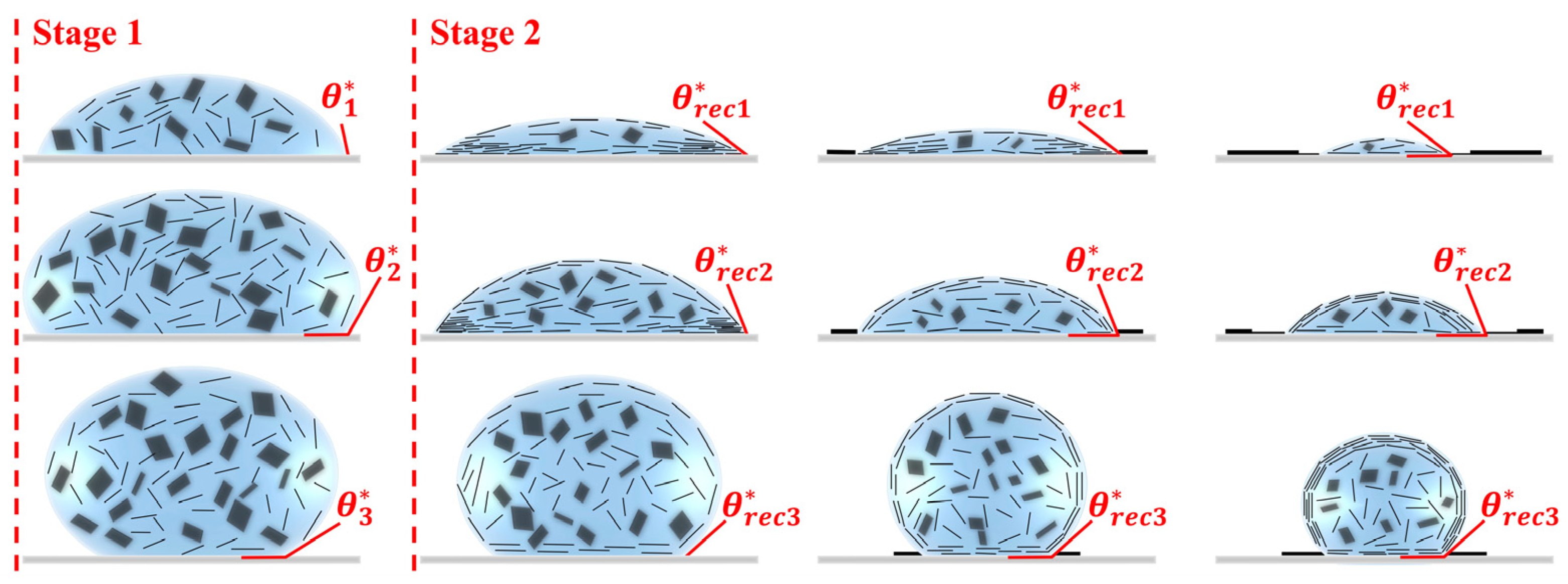
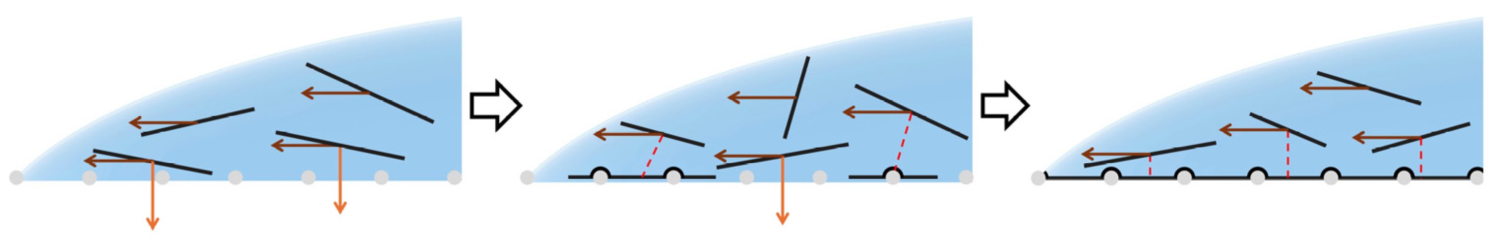
3.4. Mechanisms of GO Film Formation

The process of evaporation-induced GO film formation on fibrous membranes was as follows. As shown in Figure 4, the evaporation process could be divided into two stages: Stage 1, where θ* > θ*rec, and Stage 2, where θ* < θ*rec.
In Stage 1, the droplet contact line was pinned, a phenomenon known as the pinning effect. Evaporation occurred more rapidly at the edge than at the center of the droplet. To compensate for the water loss, a capillary flow developed from the center toward the edge. GO sheets were transported by this flow and subsequently accumulated at the edge, resulting in the coffee-ring effect.
Due to their amphiphilic nature, GO sheets could act as surfactants and reduce the surface tension [45]. As they accumulated near the droplet edge, the local surface tension decreased relative to the central region, resulting in a surface tension gradient. This gradient induced a Marangoni flow [46], which drove some GO sheets from the edge toward the center of the interface. Meanwhile, GO sheets spontaneously migrated to the air–liquid interface [29,45,47] and aligned parallel to it based on the amphiphilic nature and the principle of energy minimization [48]. As evaporation proceeded, the shrinking interface captured additional GO sheets from the droplet interior, forming a compact interfacial GO layer [48].
Concurrently, the contact angle θ* gradually decreased. When θ* became smaller than the receding contact angle θ*rec, Stage 2 was initiated. The droplet began to recede. GO sheets that had accumulated and deposited at the edge gradually evaporated with the solvent and formed a ring-like pattern. Meanwhile, the interfacial GO layer continued to capture suspended GO sheets and eventually contacted the fibrous membrane. As the liquid evaporated, the GO layer deposited on the membrane and formed a continuous film.
In summary, the evaporation-induced film formation of GO droplets on fibrous membranes involved two dominant mechanisms: the coffee-ring effect and interfacial GO layer deposition. In the following section, how the wettability of the fibrous membrane influenced the film formation mechanism is analyzed in detail.

3.4.1. Hydrophilic Fibrous Membrane

For the hydrophilic fibrous membrane, a portion of the droplet penetrated the membrane driven by gravity and capillary forces. This included GO sheets with relatively small lateral size and a portion of the water. Once the driving forces were balanced by the internal resistance of the fibrous membrane, the remaining droplet stayed on the surface and began to evaporate. Unlike the typical ring-like pattern, a belt-like GO film was formed. This was attributed to a partially suppressed coffee-ring effect.
Several factors contributed to this suppression. Due to the partial permeation, the total evaporation time was shortened, and the droplet concentration increased. There was insufficient time for a significant portion of the GO sheets to be transported to the droplet edge, and the high local concentration could hinder the generation of outward capillary flow [45]. Moreover, as shown in Figure 5, the hydrophilic nature and small pore size of the fibrous membrane induced a downward capillary flow, which hindered the outward capillary flow and captured GO sheets, resulting in fiber encapsulation and pore blockage. Furthermore, due to intersheet interactions, GO sheets transported later via capillary flow could be captured by those already encapsulating the fibers. As evaporation progressed, additional GO sheets were immobilized, eventually covering the entire region of the fibrous membrane near the droplet edge. Subsequently, intersheet interactions played a dominant role in capturing additional GO sheets.
Due to the belt-like pattern, it was inferred that only a small number of GO sheets were transported to the air–liquid interface through diffusion and Marangoni flow, and there were few GO sheets inside the droplet. This meant the partially suppressed coffee-ring effect captured most GO sheets, and interfacial GO layer deposition had only a minor effect. For the hydrophilic fibrous membrane, GO film formation was governed primarily by the partially suppressed coffee-ring effect.

3.4.2. Hydrophobic Fibrous Membrane

For the hydrophobic fibrous membrane, the droplet evaporated and formed a ring-like pattern. The pronounced coffee-ring effect was attributed to several factors. First, since no liquid penetrated the fibrous membrane, the evaporation time was longer, and the concentration was lower compared to that of the hydrophilic fibrous membrane. Moreover, due to the hydrophobicity of the fibrous membrane, no downward capillary flow was generated inside the pores, thus the outward transport of GO sheets was not hindered. Furthermore, according to the previous study, the deposition of particles at the edge could further enhance the pinning effect [49], due to the change of roughness or chemical heterogeneities [50]. When GO sheets deposited at the droplet edge, they could alter the local surface morphology and chemical properties. Therefore, it was inferred to be similar in the case of GO sheets. The GO film also formed inside the ring, suggesting interfacial GO layer deposition. The degree of fiber encapsulation by the GO film depended on the intrinsic contact angle of the fibrous membrane material. As mentioned above, the intrinsic contact angle was 98.84°, indicating that approximately the upper half of the fibers was encapsulated, which was consistent with the film morphology shown in Figure 2c.
The color of the inner GO film darkened gradually from the edge to the center. This was attributed to the fact that the GO layer contacting the fibrous membrane later could capture more GO sheets. Moreover, the dragging effect of the droplet might also contribute to this phenomenon. After the interfacial GO layer contacted the fibrous membrane, a portion of the layer was dragged inward by the receding droplet front, thereby increasing the local GO concentration and subsequently leading to the formation of a thicker GO film. For the hydrophobic fibrous membrane, GO film formation was governed by both the coffee-ring effect and interfacial GO layer deposition.

3.4.3. Superhydrophobic Fibrous Membrane
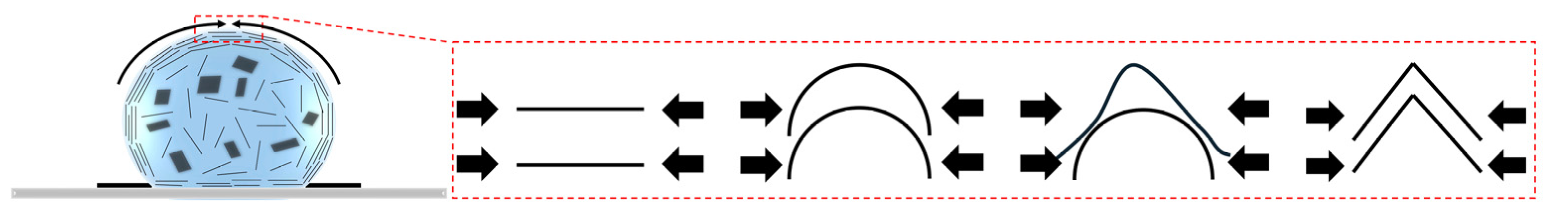
For the superhydrophobic fibrous membrane, the droplet evaporated and formed a circular pattern. For the same evaporation rate and initial volume, the pinning time depended on the difference between θ* and θ*rec. The estimated values of angular difference were 95.11° and 19.17°, respectively, indicating that the pinning time on the superhydrophobic fibrous membrane was much shorter. Only a small number of GO sheets were transported toward the edge by the outward capillary flow. Therefore, the coffee-ring effect was considered negligible during evaporation. Moreover, it could be inferred that when the droplet began to recede, only a small number of GO sheets migrated to the air–liquid interface. However, since a large number of GO sheets remained within the droplet, the interfacial GO layer grew rapidly as the air–liquid interface shrank and deposited to form a GO film. Since the intrinsic contact angle was 126.11°, only the top portion of the fibers was encapsulated by the GO layer. This was consistent with the film morphology shown in Figure 2c. Furthermore, both the fibers and the majority of GO sheets were hydrophobic, resulting in strong adhesion between them. Therefore, the GO layer was not easily dragged inward during droplet receding but remained firmly anchored to the fibrous membrane. In addition, the inability of the droplet to spread resulted in a relatively thicker GO film. These factors contributed to the formation of a circular pattern. However, sharp angles were observed for the GO film. This phenomenon is likely due to the surface irregularity of the membrane. In certain regions, unevenly distributed fibers may trap the droplet, resulting in prolonged pinning at those sites. Consequently, the retraction of the droplet contact line became nonuniform, leading to the formation of sharp angles in the GO film.
Given the large amount of GO sheets in the droplet, we further considered whether the film formation might have been driven by precipitation due to high concentration. The initial concentration used in this work was 1 mg/mL, whereas according to Fei et al. [48], GO suspensions only exhibited colloid-like behavior at concentrations around 10 mg/mL. Therefore, it could be inferred that the concentration did not play a dominant role in GO film formation. For the superhydrophobic fibrous membrane, GO film formation was governed primarily by interfacial GO layer deposition.

3.5. Wrinkling

There have been several studies on wrinkling in GO films [47,48,51,52]. As shown in Figure 6, surface tension at the air–liquid interface during evaporation has been commonly regarded as the primary driving force for wrinkle formation. During the shrinkage process, since the majority of the GO layer still consisted mainly of water, GO sheets were able to slide past one another. Consequently, the outer GO sheets were first compressed and buckled due to surface tension, followed by the inner sheets [48]. This marks the initial point of wrinkle formation [52]. In contrast, once the receding of the water front began, the increased density of GO near the contact line might have restricted interlayer slippage, resulting in collective buckling of the entire GO layer [47]. This further contributed to the formation and amplification of wrinkles.
As shown in Figure 2c, pronounced wrinkling was observed on GO films for both hydrophobic and superhydrophobic fibrous membranes. Even macroscale wrinkles were clearly visible, as shown in Figure 2b. In contrast, pronounced wrinkling was not observed on the GO film for the hydrophilic fibrous membrane. This phenomenon is discussed in detail in the following section.

3.6. Suppression of Wrinkling

As mentioned above, for the hydrophilic fibrous membrane, most GO sheets were captured and subsequently encapsulated the fibers. The influence of surface tension was minimal. This further supported the notion that the evaporation-induced GO film formation on the hydrophilic fibrous membrane was governed by the partially suppressed coffee-ring effect. Moreover, a liquid film remained when the droplet receded. According to the previous study [39], during the evaporation of the liquid film between fibers, shrinkage occurred from the center. In this process, the GO layer was stretched by the surface tension, which might eliminate potential wrinkles. Due to the high porosity of the fibrous membrane, the GO layer experienced extensive stretching across most of its surface. For the hydrophobic fibrous membrane, less liquid film remained, resulting in weaker stretching effects. For the superhydrophobic fibrous membrane, since the liquid film could be negligible, there was no stretching effect. These factors contributed to the suppression of wrinkling on the GO film formed on the hydrophilic fibrous membrane.

4. Conclusions

The spreading experiments demonstrated the distinct spreading behaviors of GO droplets on fibrous membranes with varying wettability. On the hydrophilic fibrous membrane, the droplet partially penetrated the membrane. On the hydrophobic fibrous membrane, the droplet was manually spread into a defined area. On the superhydrophobic fibrous membrane, the droplet maintained a spherical shape and rolled across the surface. These behaviors were strongly correlated with θ*rec (θ*rec,h = 40.89° for the hydrophobic fibrous membrane and θ*rec,s = 133.33° for the superhydrophobic fibrous membrane).
The evaporation-induced GO film formation was primarily governed by two mechanisms: the coffee-ring effect and interfacial GO layer deposition. Their relative contributions varied with membrane wettability. On the hydrophilic fibrous membrane, due to droplet penetration and capillary absorption, GO film formation was governed by the suppressed coffee-ring effect. The droplet formed a belt-like pattern and largely encapsulated the fibers. On the hydrophobic fibrous membrane, due to the large contact angle hysteresis (Δθh = 95.11°) and the absence of liquid loss, GO film formation was governed by both the coffee-ring effect and interfacial GO layer deposition. The droplet formed a ring-shaped pattern with an additional inner film, encapsulating approximately the upper half of the fibers. On the superhydrophobic fibrous membrane, due to a much smaller contact angle hysteresis (Δθs = 19.17°), GO film formation was governed by interfacial GO layer deposition. The droplet formed a circular pattern, encapsulating the top portion of the fibers. The film formation on nonwoven fibrous membranes with varying wettability is summarized in Table 4. During evaporation, surface tension compressed the GO sheets and induced wrinkling. However, for the hydrophilic fibrous membrane, the influence of surface tension was minimal, and the presence of the remaining liquid film between fibers during droplet receding resulted in stretching of the GO layer. Therefore, pronounced wrinkling was not observed on the GO film supported by the hydrophilic membrane.
This work demonstrated that GO film morphology, including fiber encapsulation, wrinkling, and coverage area can be effectively controlled by selecting fibrous membranes with different wettability. The stability and separation performance of GO films on various fibrous membranes should be investigated in future studies.

Author Contributions

Conceptualization, F.G.; Methodology, F.G. and Z.L.; Formal analysis, Z.L.; Investigation, Z.L., J.F., J.X., F.G.; Writing—original draft preparation, Z.L.; Writing—review and editing, F.G. and J.X.; Supervision, F.G. All authors have read and agreed to the published version of the manuscript.

Funding

This research received no external funding.

Data Availability Statement

The raw data supporting the conclusions of this article will be made available by the authors on request.

Conflicts of Interest

The authors declare no conflict of interest.

References

  1. Deegan, R.D.; Bakajin, O.; Dupont, T.F.; Huber, G.; Nagel, S.R.; Witten, T.A. Capillary Flow as the Cause of Ring Stains from Dried Liquid Drops. Nature 1997, 389, 827–829. [Google Scholar] [CrossRef]
  2. Suk, J.W.; Piner, R.D.; An, J.; Ruoff, R.S. Mechanical Properties of Monolayer Graphene Oxide. ACS Nano 2010, 4, 6557–6564. [Google Scholar] [CrossRef] [PubMed]
  3. Asghar, F.; Shakoor, B.; Fatima, S.; Munir, S.; Razzaq, H.; Naheed, S.; Butler, I.S. Fabrication and Prospective Applications of Graphene Oxide-Modified Nanocomposites for Wastewater Remediation. RSC Adv. 2022, 12, 11750–11768. [Google Scholar] [CrossRef] [PubMed]
  4. Kong, Y.; Zhang, X.; Wang, Q.; Liu, Y.; Liu, G.; Wang, K. Enhancing Helium Separation by Ionic-Liquid-Modulated Nanoporous Graphene Oxide Membrane. J. Membr. Sci. 2025, 722, 123861. [Google Scholar] [CrossRef]
  5. Voiry, D.; Yang, J.; Kupferberg, J.; Fullon, R.; Lee, C.; Jeong, H.Y.; Shin, H.S.; Chhowalla, M. High-Quality Graphene via Microwave Reduction of Solution-Exfoliated Graphene Oxide. Science 2016, 353, 1413–1416. [Google Scholar] [CrossRef]
  6. Liu, Z.-B.; Xu, Y.-F.; Zhang, X.-Y.; Zhang, X.-L.; Chen, Y.-S.; Tian, J.-G. Porphyrin and Fullerene Covalently Functionalized Graphene Hybrid Materials with Large Nonlinear Optical Properties. J. Phys. Chem. B 2009, 113, 9681–9686. [Google Scholar] [CrossRef]
  7. Renteria, J.D.; Ramirez, S.; Malekpour, H.; Alonso, B.; Centeno, A.; Zurutuza, A.; Cocemasov, A.I.; Nika, D.L.; Balandin, A.A. Strongly Anisotropic Thermal Conductivity of Free-Standing Reduced Graphene Oxide Films Annealed at High Temperature. Adv. Funct. Mater. 2015, 25, 4664–4672. [Google Scholar] [CrossRef]
  8. Hu, X.; Zhou, J.; Mu, X.; Qiu, C.; Kang, M.; Zhang, Z.; Gao, J.; Liu, J.; Miao, L. Photo-Fenton Catalyst Embedded in Photothermal Aerogel for Efficient Solar Interfacial Water Evaporation and Purification. Green Carbon 2024, S2950155524000843, in press. [Google Scholar] [CrossRef]
  9. Wei, W.; Wei, Z.; Li, R.; Yuan, H.; Chen, J.; Lv, J.; Ouyang, S. Fine-Tuning N-Doped Species of C Catalysts for 98% Current Efficiency of Electrocatalytic Decarboxylation into Hindered Ether. Green Carbon 2024, 2, 291–299. [Google Scholar] [CrossRef]
  10. He, P.; Derby, B. Controlling Coffee Ring Formation during Drying of Inkjet Printed 2D Inks. Adv. Mater. Interfaces 2017, 4, 1700944. [Google Scholar] [CrossRef]
  11. Zhang, Q.; Qian, X.; Thebo, K.H.; Cheng, H.-M.; Ren, W. Controlling Reduction Degree of Graphene Oxide Membranes for Improved Water Permeance. Sci. Bull. 2018, 63, 788–794. [Google Scholar] [CrossRef] [PubMed]
  12. Liu, T.; Huang, S.; Xin, W.; He, X.; Wan, S.; Yang, C.; Zhao, J.; Shi, L.; Yan, H.; Zhou, T.; et al. High-Performance Graphene Oxide / Sodium Alginate Composite Membrane for Marine Osmotic Energy Conversion. J. Membr. Sci. 2025, 724, 123987. [Google Scholar] [CrossRef]
  13. Xing, C.; Liu, C.-Y.; Lai, C.; Zhang, S.-Q. Tuning D-Spacing of Graphene Oxide Nanofiltration Membrane for Effective Dye/Salt Separation. Rare Met. 2023, 42, 418–429. [Google Scholar] [CrossRef]
  14. Mazlan, N.A.; Lewis, A.; Chen, Z.; Butt, F.S.; Han, J.; Radacsi, N.; Yang, S.; Huang, Y. Photocatalytic Self-Cleaning Graphene Oxide/ZnO Hybrid Membrane for Ultrafast Cyclic Small Organic Molecule Separation. J. Membr. Sci. 2024, 697, 122539. [Google Scholar] [CrossRef]
  15. Kim, J.P.; Go, C.Y.; Kang, J.; Choi, Y.; Kim, J.Y.; Kim, J.; Kwon, O.; Kim, K.C.; Kim, D.W. Nanoporous Multilayer Graphene Oxide Membrane for Forward Osmosis Metal Ion Recovery from Spent Li-Ion Batteries. J. Membr. Sci. 2023, 676, 121590. [Google Scholar] [CrossRef]
  16. Wang, J.; Zhang, P.; Liang, B.; Liu, Y.; Xu, T.; Wang, L.; Cao, B.; Pan, K. Graphene Oxide as an Effective Barrier on a Porous Nanofibrous Membrane for Water Treatment. ACS Appl. Mater. Interfaces 2016, 8, 6211–6218. [Google Scholar] [CrossRef]
  17. Guan, K.; Shen, J.; Liu, G.; Zhao, J.; Zhou, H.; Jin, W. Spray-Evaporation Assembled Graphene Oxide Membranes for Selective Hydrogen Transport. Sep. Purif. Technol. 2017, 174, 126–135. [Google Scholar] [CrossRef]
  18. Li, Z.; Li, Z.; Zhang, N.; Bao, J.; Zhang, X.; He, G.; Chen, C.; Song, Y. Ultra-Thin Size-Sieving Gas Separation Membrane by Precisely Contra-Diffusion-Match Growth of ZIF-67 among GO Laminates. J. Membr. Sci. 2024, 694, 122428. [Google Scholar] [CrossRef]
  19. Chong, J.; Wang, B.; Li, K. Graphene Oxide Membranes in Fluid Separations. Curr. Opin. Chem. Eng. 2016, 12, 98–105. [Google Scholar] [CrossRef]
  20. Kong, F.; Liu, Q.; Dong, L.; Zhang, T.; Wei, Y.; Chen, J.; Wang, Y.; Guo, C. Rejection of Pharmaceuticals by Graphene Oxide Membranes: Role of Crosslinker and Rejection Mechanism. J. Membr. Sci. 2020, 612, 118338. [Google Scholar] [CrossRef]
  21. Wu, D.; He, Y.; Wu, J.; He, Y.; Peng, W. Photocatalytic Self-Cleaning Holey Graphene Oxide Membranes by a Synergistic Strategy of Etching and Intercalation for Efficient Dye Separation. J. Membr. Sci. 2025, 716, 123514. [Google Scholar] [CrossRef]
  22. Zhang, N.; Yu, H.; Cui, H.; Xiao, H.; Jiang, X.; Dai, Y.; Zhang, X.; Bao, J.; He, G. Bio-Inspired Molecular Bridge Anchoring GO Laminates onto PAN Substrate for Molecular Separation. Adv. Membr. 2022, 2, 100034. [Google Scholar] [CrossRef]
  23. Wang, Z.; Li, N.; He, X.; Yi, C.; Xie, Z. Super-Crosslinked Graphene Oxide Membranes with Enhanced Stability and Selectivity for Efficient Alcohol/Water Separation via Pervaporation. J. Membr. Sci. 2025, 720, 123776. [Google Scholar] [CrossRef]
  24. Xu, Z.; Yan, X.; Du, Z.; Li, J.; Cheng, F. Effect of Oxygenic Groups on Desalination Performance Improvement of Graphene Oxide-Based Membrane in Membrane Distillation. Sep. Purif. Technol. 2020, 251, 117304. [Google Scholar] [CrossRef]
  25. Zeynali, R.; Ghasemzadeh, K.; Sarand, A.B.; Kheiri, F.; Basile, A. Performance Evaluation of Graphene Oxide (GO) Nanocomposite Membrane for Hydrogen Separation: Effect of Dip Coating Sol Concentration. Sep. Purif. Technol. 2018, 200, 169–176. [Google Scholar] [CrossRef]
  26. Hu, M.; Mi, B. Layer-by-Layer Assembly of Graphene Oxide Membranes via Electrostatic Interaction. J. Membr. Sci. 2014, 469, 80–87. [Google Scholar] [CrossRef]
  27. Tsou, C.-H.; An, Q.-F.; Lo, S.-C.; De Guzman, M.; Hung, W.-S.; Hu, C.-C.; Lee, K.-R.; Lai, J.-Y. Effect of Microstructure of Graphene Oxide Fabricated through Different Self-Assembly Techniques on 1-Butanol Dehydration. J. Membr. Sci. 2015, 477, 93–100. [Google Scholar] [CrossRef]
  28. Chong, W.S.; Gan, S.X.; Al-Tuwirit, H.M.; Chong, W.Y.; Lim, C.S.; Ahmad, H. Nanolitre Solution Drop-Casting for Selective Area Graphene Oxide Coating on Planar Surfaces. Mater. Chem. Phys. 2020, 249, 122970. [Google Scholar] [CrossRef]
  29. Zhao, C.; Xing, L.; Xiang, J.; Cui, L.; Jiao, J.; Sai, H.; Li, Z.; Li, F. Formation of Uniform Reduced Graphene Oxide Films on Modified PET Substrates Using Drop-Casting Method. Particuology 2014, 17, 66–73. [Google Scholar] [CrossRef]
  30. Zhang, M.; Sun, J.; Mao, Y.; Liu, G.; Jin, W. Effect of Substrate on Formation and Nanofiltration Performance of Graphene Oxide Membranes. J. Membr. Sci. 2019, 574, 196–204. [Google Scholar] [CrossRef]
  31. Kim, T.; Cho, H.; Choi, S.T.; Nam, W.; Lee, S.; Liang, H.; Kim, S. Controlled Deposition of Graphene Oxide on an Anodic Aluminum Oxide Substrate via Coffee-Ring Effect. J. Alloys Compd. 2023, 958, 170464. [Google Scholar] [CrossRef]
  32. Burton, N.D.; Zarshenas, K.; Somvanshi, C.; Chekini, M.; Grishkewich, N.; Ghanbari, S.; Abdala, A.; Gostick, J.T.; Pope, M.A. Unleashing the Potential of Scalable, High-Water Vapor Permeance Graphene Oxide Membranes Using Electrospun Supports. J. Membr. Sci. 2024, 690, 122142. [Google Scholar] [CrossRef]
  33. Gopal, R.; Kaur, S.; Feng, C.Y.; Chan, C.; Ramakrishna, S.; Tabe, S.; Matsuura, T. Electrospun Nanofibrous Polysulfone Membranes as Pre-Filters: Particulate Removal. J. Membr. Sci. 2007, 289, 210–219. [Google Scholar] [CrossRef]
  34. Feng, C.; Khulbe, K.C.; Matsuura, T.; Tabe, S.; Ismail, A.F. Preparation and Characterization of Electro-Spun Nanofiber Membranes and Their Possible Applications in Water Treatment. Sep. Purif. Technol. 2013, 102, 118–135. [Google Scholar] [CrossRef]
  35. Burger, C.; Hsiao, B.S.; Chu, B. Nanofibrous Materials and Their Applications. Annu. Rev. Mater. Res. 2006, 36, 333–368. [Google Scholar] [CrossRef]
  36. Yoon, K.; Hsiao, B.S.; Chu, B. Functional Nanofibers for Environmental Applications. J. Mater. Chem. 2008, 18, 5326. [Google Scholar] [CrossRef]
  37. Rashid, T.U.; Gorga, R.E.; Krause, W.E. Mechanical Properties of Electrospun Fibers—A Critical Review. Adv. Eng. Mater. 2021, 23, 2100153. [Google Scholar] [CrossRef]
  38. Wu, W.; Yu, L.; Li, L.; Li, Z.; Kang, J.; Pu, S.; Chen, D.; Ma, R.; An, K.; Liu, G.; et al. Electrospun Nanofiber Based Forward Osmosis Membrane Using Graphene Oxide as Substrate Modifier for Enhanced Water Flux and Rejection Performance. Desalination 2021, 518, 115283. [Google Scholar] [CrossRef]
  39. Cheng, C.; Shen, L.; Yu, X.; Yang, Y.; Li, X.; Wang, X. Robust Construction of a Graphene Oxide Barrier Layer on a Nanofibrous Substrate Assisted by the Flexible Poly(Vinylalcohol) for Efficient Pervaporation Desalination. J. Mater. Chem. A 2017, 5, 3558–3568. [Google Scholar] [CrossRef]
  40. Krishnamoorthi, R.; Butt, F.S.; Mazlan, N.A.; Chen, S.; Radacsi, N.; Yang, S.; Yoon, Y.; Huang, Y. Tuning the Interlayer Spacing of Graphene Oxide Membrane via Surfactant Intercalation for Ultrafast Nanofiltration. J. Membr. Sci. 2024, 706, 122942. [Google Scholar] [CrossRef]
  41. Lowery, J.L.; Datta, N.; Rutledge, G.C. Effect of Fiber Diameter, Pore Size and Seeding Method on Growth of Human Dermal Fibroblasts in Electrospun Poly(ɛ-Caprolactone) Fibrous Mats. Biomaterials 2010, 31, 491–504. [Google Scholar] [CrossRef] [PubMed]
  42. Choi, W.; Tuteja, A.; Mabry, J.M.; Cohen, R.E.; McKinley, G.H. A Modified Cassie–Baxter Relationship to Explain Contact Angle Hysteresis and Anisotropy on Non-Wetting Textured Surfaces. J. Colloid Interface Sci. 2009, 339, 208–216. [Google Scholar] [CrossRef] [PubMed]
  43. Dikin, D.A.; Stankovich, S.; Zimney, E.J.; Piner, R.D.; Dommett, G.H.B.; Evmenenko, G.; Nguyen, S.T.; Ruoff, R.S. Preparation and Characterization of Graphene Oxide Paper. Nature 2007, 448, 457–460. [Google Scholar] [CrossRef] [PubMed]
  44. Cai, J.; Liu, X.; Zhao, Y.; Guo, F. Membrane Desalination Using Surface Fluorination Treated Electrospun Polyacrylonitrile Membranes with Nonwoven Structure and Quasi-Parallel Fibrous Structure. Desalination 2018, 429, 70–75. [Google Scholar] [CrossRef]
  45. Kim, J.; Cote, L.J.; Kim, F.; Yuan, W.; Shull, K.R.; Huang, J. Graphene Oxide Sheets at Interfaces. J. Am. Chem. Soc. 2010, 132, 8180–8186. [Google Scholar] [CrossRef]
  46. Soltman, D.; Subramanian, V. Inkjet-Printed Line Morphologies and Temperature Control of the Coffee Ring Effect. Langmuir 2008, 24, 2224–2231. [Google Scholar] [CrossRef]
  47. Hong, S.-H.; Shen, T.-Z.; Song, J.-K. Water Front Recession and the Formation of Various Types of Wrinkles in Dried Graphene Oxide Droplets. Carbon 2016, 105, 297–304. [Google Scholar] [CrossRef]
  48. Guo, F.; Kim, F.; Han, T.H.; Shenoy, V.B.; Huang, J.; Hurt, R.H. Hydration-Responsive Folding and Unfolding in Graphene Oxide Liquid Crystal Phases. ACS Nano 2011, 5, 8019–8025. [Google Scholar] [CrossRef]
  49. McBride, S.A.; Atis, S.; Pahlavan, A.A.; Varanasi, K.K. Crystal Patterning from Aqueous Solutions via Solutal Instabilities. ACS Appl. Mater. Interfaces 2024, 16, 70980–70990. [Google Scholar] [CrossRef]
  50. Deegan, R.D.; Bakajin, O.; Dupont, T.F.; Huber, G.; Nagel, S.R.; Witten, T.A. Contact Line Deposits in an Evaporating Drop. Phys. Rev. E 2000, 62, 756–765. [Google Scholar] [CrossRef]
  51. Shen, X.; Lin, X.; Yousefi, N.; Jia, J.; Kim, J.-K. Wrinkling in Graphene Sheets and Graphene Oxide Papers. Carbon 2014, 66, 84–92. [Google Scholar] [CrossRef]
  52. Luo, Y.; Braggin, G.A.; Olson, G.T.; Stevenson, A.R.; Ruan, W.L.; Zhang, S. Nematic Order Drives Macroscopic Patterns of Graphene Oxide in Drying Drops. Langmuir 2014, 30, 14631–14637. [Google Scholar] [CrossRef]
Figure 1. (a) A lab-scale electrospinning setup and (b) a custom-built iCVD reactor.
Surfaces 08 00039 g001
Figure 2. (a) Contact angle measurements of hydrophilic (orange), hydrophobic (green), and superhydrophobic (blue) fibrous membranes with DI water (top) and GO suspension (bottom). (b) The GO film preparations via the drop-casting method on hydrophilic (orange), hydrophobic (green), and superhydrophobic (blue) fibrous membranes. (c) SEM images of hydrophilic (orange), hydrophobic (green), and superhydrophobic (blue) fibrous membranes, as well as GO films. Scale bars: 20 μm (middle), 5 μm (top and bottom).
Surfaces 08 00039 g002
Figure 3. (a) Spreading behavior of GO droplets on hydrophilic (orange), hydrophobic (green), and superhydrophobic (blue) fibrous membranes. (b) Contact between the droplet and the fibrous membrane. (c) Receding behavior of the droplet on hydrophobic (top) and superhydrophobic (bottom) fibrous membranes.
Surfaces 08 00039 g003
Figure 4. GO film formation on hydrophilic, hydrophobic, and superhydrophobic fibrous membranes.
Surfaces 08 00039 g004
Figure 5. Suppression of the coffee-ring effect on the hydrophilic fibrous membrane. The arrows show the stepwise suppression process from left to right.
Surfaces 08 00039 g005
Figure 6. Wrinkling during GO film formation. The arrows indicate the direction of surface tension.
Surfaces 08 00039 g006
Table 1. Electrospinning processing parameters.
MaterialConcentration (wt%)Temperature (°C)Humidity (%)Distance (cm)Flow Rate (mL/min) Positive
Voltage (kV)
Negative Voltage (kV)
PAN132520200.015154
PVDF162520200.015154
Table 2. Fiber diameters of fibrous membranes.
MaterialFiber Distribution (nm)AmountAverage (nm)
PAN200–30014300
300–40016
PVDF 100–200320
200–300
300–400
400–500
500–600
Surface fluorinated PAN200–30020290
300–4008
400–5002
Table 3. Wettability of fibrous membranes.
MaterialContact Angle (°)Wettability
PANUnmeasuredHydrophilic
PVDF120–144 (DI water)Hydrophobic
129–143 (GO suspension)
Surface-fluorinated PAN152–157 (DI water)Superhydrophobic
151–154 (GO suspension)
Table 4. Morphologies and formation mechanisms of GO films on nonwoven fibrous membranes with varying wettability.
WettabilityPatternFiber EncapsulationWrinkleMechanism
HydrophilicBeltMore than the upper halfNegligibleSuppressed coffee-ring effect
HydrophobicRingApproximately the upper halfPronouncedCoffee-ring effect +
interfacial GO layer deposition
SuperhydrophobicCircularThe top portionPronouncedInterfacial GO layer deposition
Disclaimer/Publisher’s Note: The statements, opinions and data contained in all publications are solely those of the individual author(s) and contributor(s) and not of MDPI and/or the editor(s). MDPI and/or the editor(s) disclaim responsibility for any injury to people or property resulting from any ideas, methods, instructions or products referred to in the content.

