Review

A Brief Insight to the Electrophoretic Deposition of PEEK-, Chitosan-, Gelatin-, and Zein-Based Composite Coatings for Biomedical Applications: Recent Developments and Challenges

by
Syeda Ammara Batool
,
Abdul Wadood
,
Syed Wilayat Hussain
,
Muhammad Yasir
and
Muhammad Atiq Ur Rehman
*
Department of Materials Science and Engineering, Institute of Space Technology Islamabad, Islamabad 44000, Pakistan
*
Author to whom correspondence should be addressed.
Surfaces 2021, 4(3), 205-239; https://doi.org/10.3390/surfaces4030018
Submission received: 20 June 2021 / Revised: 20 July 2021 / Accepted: 21 July 2021 / Published: 4 August 2021

Abstract

:
Electrophoretic deposition (EPD) is a powerful technique to assemble metals, polymer, ceramics, and composite materials into 2D, 3D, and intricately shaped implants. Polymers, proteins, and peptides can be deposited via EPD at room temperature without affecting their chemical structures. Furthermore, EPD is being used to deposit multifunctional coatings (i.e., bioactive, antibacterial, and biocompatible coatings). Recently, EPD was used to architect multi-structured coatings to improve mechanical and biological properties along with the controlled release of drugs/metallic ions. The key characteristics of EPD coatings in terms of inorganic bioactivity and their angiogenic potential coupled with antibacterial properties are the key elements enabling advanced applications of EPD in orthopedic applications. In the emerging field of EPD coatings for hard tissue and soft tissue engineering, an overview of such applications will be presented. The progress in the development of EPD-based polymeric or composite coatings, including their application in orthopedic and targeted drug delivery approaches, will be discussed, with a focus on the effect of different biologically active ions/drugs released from EPD deposits. The literature under discussion involves EPD coatings consisting of chitosan (Chi), zein, polyetheretherketone (PEEK), and their composites. Moreover, in vitro and in vivo investigations of EPD coatings will be discussed in relation to the current main challenge of orthopedic implants, namely that the biomaterial must provide good bone-binding ability and mechanical compatibility.

1. Introduction

Electrophoretic deposition (EPD) is a versatile technique for depositing metals, metal oxides, polymers, ceramics, and their complex combinations. Various applications of EPD include production of dye-sensitized solar cells, solid oxide fuel cells, batteries, capacitors, fiber-reinforced composites, sensors, corrosion-resistant coatings, deposition of nanotubes, and biomedical materials [1,2,3,4,5,6,7].
EPD is a commonly applied method in the field of biomaterials, especially for producing bioactive coatings [8,9,10,11,12,13]. EPD is helpful in processing micro- and nanostructured biomaterials in simple as well as complex form [14,15,16,17]. EPD provides a simple setup consisting of two electrodes. Two kinds of power sources, alternating current (AC) and direct current (DC), can be applied for EPD [18,19]. The freedom to manipulate nanoparticles in the suspension has brought a lot of new interest to the process. The adjustable shape of the substrates, deposition of materials at room temperature, and the possibility to adjust the thickness as well as the morphology of the coatings by optimizing process parameters, such as applied voltage, the concentration of suspension, and deposition time, make EPD a potential processing method for depositing biopolymers for research purposes and also at large scale [20,21].
In the biomedical field, deposition of thin films or coatings on porous structures, such as on scaffolds, is of great interest, and has become an essential part of tissue engineering and regenerative medicine [22,23,24,25,26]. EPD allows a homogeneous coating consisting of bioactive layers and biological entities (proteins, polymers, enzymes, cells, etc.) with therapeutic metallic ions or drugs on various substrates [27,28]. The development of hydroxyapatite (HA) coatings on Ti substrate, confirming the induced bioactivity of the substrate, gained a lot of attention and initiated further investigations in 1986 [29].
Biomaterial coatings should possess some important properties for their effective utilization in the implant devices, such as biocompatibility, bioactivity, antibacterial effect, surface wettability, adhesion strength, corrosion, wear resistance, and so on. The interaction of coating surface and cells is of crucial consideration when designing the coating material. In some cases, there is a need to modify the surface properties of the base material by depositing an appropriate coating. For example, graphene oxide (GO) was applied on Al substrate to enhance the anticorrosive properties of Al [30]. Similarly, sometimes the surfaces are not responsive to the environment of their application, and we know that in case of biomaterials, wettability is an important factor. Again, EPD can alter the wetting behavior of the base materials [31]. The biomedical coatings are characterized on the basis of various investigative methods for the above-mentioned properties, for example, the formation of HA on coated samples in simulated body fluid (SBF) or phosphate buffer saline (PBS) solution for bioactivity, using cell-line studies for biocompatibility and cell attachment and growth, minimum inhibition zone tests for antibacterial effect, water contact angle measurement for wettability, pencil hardness and scratch tests for adhesion strength, and so on. The characterization of biomaterial coatings are further discussed in detail in the sections of chitosan, zein, and PEEK EPD coatings [32,33,34,35].
Now, EPD is gaining more and more attention due to its applicability for depositing different materials and their complex combinations. Materials deposited via EPD include metals, polymers, ceramics, glasses, and their composites [36,37,38,39,40]. It is also a cost-effective technique, requiring a simple assembly of readily available equipment. Moreover, it is a good technique for depositing large surface areas (from micrometers to meters) and different component shapes.
In this review paper, we will discuss the fundamentals and working of the EPD process, classification of EPD, the key factors, and kinetics on which the performance of EPD is dependent. In the next sections, a detailed discussion on the EPD of biopolymers (chi, zein, PEEK) and their composite coatings with ceramic inclusions and various metallic ions will be presented. The literature and results presented here focus on the last two decades of in vitro and in vivo evaluation of biomaterials for biomedical applications. We focused on the EPD for biostable coatings, suitable for aged patients, and biodegradable coatings, which are suitable for younger patients who can regenerate bones. Among other biopolymers, research is focused on zein, chitosan, and PEEK, due to their biocompatible nature and ease of availability. Thus, we have emphasized EPD of the selected biopolymers in this review.

2. Electrophoretic Deposition

EPD is a technique for processing suspensions in which deposition occurs on the oppositely charged substrate as the result of migration of charged particles in the suspension when subjected to an electric field. It is a flexible technique, well-suited to the processing of polymers, ceramics, and composites. The EPD process occurs in two stages. The first stage is the generation of positive or negative charge on the suspension/colloidal species, followed by their movement towards oppositely charged electrode due to applied current, known as electrophoresis. Some materials inherently have charge on their surface due to some functional groups, or the charge on the species can be generated by adding an acid or a base to the suspension. The second stage involves the deposition of the charged species on the surface of the oppositely charged electrodes due to the coagulation of particles [7,41,42]. The basic setup of EPD consists of two electrodes adjusted in parallel, dipped in the charged suspension, and connected with a power source, as shown in Figure 1. The power source enables the unification and deposition of charged particles, in the form of thick or thin coatings, onto substrates of any shape and any size.

2.1. Classification of EPD

The EPD process is generally divided in two main types, that is, cathodic EPD and anodic EPD. Cathodic EPD is defined as the deposition of positive charges on the cathode (i.e., negative electrode) (Figure 1) and anodic EPD is the deposition of negative charges on the anode (i.e., positive electrode).
EPD is also categorized based on the type of supplied electric signal. The electric field is either provided as DC or AC. DC and AC signals are divided into constant DC (CDC) and pulsed DC (PDC), and symmetrical AC and asymmetrical AC (without and with DC component), respectively [43]. Figure 2 represents various types of electric signals supplied to the process.
Although the choice of the electric signal depends on the required physical and chemical properties of the deposited film, in general, AC-EPD has few advantages over DC-EPD. In DC-EPD, the electrolysis of water takes place in the aqueous suspensions at a low voltage as well, which causes hydrogen and oxygen gases to evolve at the cathode and anode, respectively. The bubble formation on the depositing electrode results in the porosity of coating generating poor mechanical properties. This problem can be overcome by applying AC signals instead of DC signals in aqueous electrolytes. The application of AC prevents or minimizes the electrolysis of water molecules and produces denser coatings of good quality [44]. This phenomenon is especially important in the EPD of sensitive biological and biochemical species such as cells, enzymes, and proteins, where consolidation of said entities depends on the electrophoresis mobility [45,46].

2.2. Key Parameters Affecting EPD

Several factors influence the deposition process and deposition yield in EPD. The first and foremost requirement for the process is to form a stable suspension of positively or negatively charged particles. These particles move towards anode or cathode depending upon their charge and get deposited on the respective electrodes. The parameters influencing the EPD process can be divided into two categories: parameters associated with suspension stability and parameters associated with the deposition process [41,47].
Electrophoresis is the migration of charged particles or molecules in a suspension when an electric field is applied. Various factors affecting the mobility of charged particles are mainly related to the characteristics of the suspension. Equation (1) [48] mathematically relates the prominent factors influencing electrophoretic mobility (EM).
µ = 2εζ/3η f(ka)
where:
  • µ, EM;
  • ε, dielectric constant;
  • ζ, zeta-potential;
  • η, viscosity;
  • f(ka), Henry’s function.
According to Equation (1), µ increases with increasing dielectric constant and zeta potential values, whereas it decreases for high viscosity values. It is imperative to optimize all the factors involved in the process to produce high-quality films or coatings [49]. These factors are discussed one by one.

2.2.1. Parameters Related to Suspension Stability

(a) Zeta potential
Electrokinetic potential, or zeta potential, is the charge that develops at the boundary of a solid and a liquid medium. Almost all the particles coming in contact with a liquid medium attain an electronic charge on their surface. This potential is measured in millivolts (mV) [50]. As shown in Figure 3, a layer of positively charged ions is accumulated over the surface of the negatively charged particle. The total charge on the particle surface decides the nearby ionic distribution, forming an electric double layer (EDL) in the region of the solid–liquid interface. The inner side of the EDL (i.e., the stern layer) contains ions firmly adherent to the surface of the particle, and at the outer side of the EDL (i.e., the slipping plane), the ions gather as a result of electrostatic forces. Zeta potential is the sum of surface charge generated initially and the charge of accumulated layers [51].
The overall stability of the suspension depends on the zeta potential value of particles. It helps determine the intensity of repulsive forces between particles of similar charge, which directly influences suspension stability. Highly charged particles are required to produce a considerable electrostatic repulsion, preventing the flocculation and settling of the weakly charged particles. In addition, particles with high surface charge will have more energy to move through the electrolyte. Thus, a high zeta potential is required for good EM.
Zeta potential calculations exhibit surface functionality, stability of the dispersed particles in suspension, and the interaction of dissolved compounds with the surface of the solid [53]. Zeta potential reflects the electrostatic repulsion of particles among themselves. In general consideration, zeta potential values above +30 mV and below −30 mV indicate stable dispersion of particles [54,55], as depicted in the plot of Figure 3. The magnitude of zeta potential indicates the stability of the suspension, whereas the sign of zeta potential shows the dominancy of positive or negative charge at the surface. Outside the limit of ± 30 mV, particles are likely to aggregate and settle down in the container.
(b) pH of suspension
Zeta potential is a function of pH, as we can induce the required charge in the suspension by adding weak acids, bases, and ions from metallic salts. A lower pH value indicates a lower ionization rate of the acid and a higher pH value indicates a high ionization rate of the added acid; thus, pH determines the degree of ionization [55]. At elevated ionization rates, the acid or base will produce more charged particles in the suspension, which will elevate the electrophoretic mobility.
(c) Viscosity of solvents
Viscosity of solvents indirectly relates to the EM. The higher the viscosity, the lower will be the EM [56]. Solvents having low viscosity values tend to achieve higher mobility, resulting in good deposition.
(d) Dielectric constant of liquid
Generally, EM tends to increase with the dielectric constant of the liquid [57]. At low dielectric constant value, EM is very slow due to insufficient dissociative energy required by the particles for good deposition [41]. At high values of dielectric constant, the size of the double layer decreases due to high ionic concentration, which, in turn, reduces the rate of EM.
(e) Conductivity of suspension
There exist an inverse relation between EM and conduction of the suspension [58]. Low ionic conduction favors the EM, and high conductivity values impose resistance to the particle motion. The conductivity of the suspension differs from that of the pure liquid. The impurities/solute forming the suspension greatly affect its properties, and EM is also one of them. When a suspension is highly conductive, particles move at a slow rate, and when a suspension is highly resistive, the stability of the charged particles gets lost due to electronic charging. Therefore, there is a narrow range of conductivity values over which a good deposition of particles is achieved.
(f) Particle size
Particle size and morphology directly affects the zeta potential of suspension [50]. It is important that the particles in suspension remain stable and uniformly dispersed. If the particle size is too large, they will settle down under the gravitational effect. The mobility of particles under applied electric field should be more than that of particles mobility under the effect of gravitational field. EM is large for small-sized particles, as particles less than 1µm in size remain in the suspension and do not settle down owing to their natural Brownian motion, thus providing thick and uniform coating with enhanced properties [59]. For large-sized particles to have effective mobility, a strong electric field is needed.

2.2.2. Parameters Related to Processing

(a) Effect of deposition time
As time passes, the deposition rate at a certain applied electric field decreases. During the initial stage of the EPD process, the deposition increases linearly with time, but after some time, a level is attained after which no further deposition is achieved. The reason for this is the formation of a deposit on the surface of the electrode which acts as an insulator, inhibiting further attachment of the particles [60,61].
(b) Effect of applied voltage
The force responsible for the EPD process is applied voltage or electric field. There are also free ions present in the suspension that take up some of the electric energy. The ample amount of applied field is necessary to trigger the process of EPD. At low fields, the particles do not even get to move in the suspension. The deposition rate increases with the amount of applied voltage. An optimum range of applied field should be selected for the EPD process to run, because the high electric field affects the quality of deposited film too. With high voltage, particles move rapidly and do not get enough time to deposit uniformly on the substrate [62].
(c) Conductivity of substrate
The substrate conductivity holds an important place in the quality of deposit. Substrates having low conductivity values leads to low deposition yield, even after long periods of time [63]. The deposited film is also non-uniform in thickness.
(d) Concentration of material
The concentration of a specific material in the suspension plays a significant role in the EPD process, especially in the case of multi-component systems [64]. The particles in the suspension have the same charge on the surface, so their deposition rate should be same. However, the volume fraction of particles in the suspension affects the rate of deposition. A high volume fraction attains uniform deposition at elevated rates. As for a low volume fraction, the deposition rate is determined by the individual EM.

2.3. EPD Kinetics

As discussed above, a lot of factors involving suspension properties and processing conditions affect the outcome of EPD; this is why it is important to optimize the parameters to produce high quality products [65]. Various theories to explain the mechanism behind the EPD process have been proposed over the years. Hamaker et al. [66] correlated the EPD processing parameters with the deposition kinetics. According to Hamaker’s law, deposition yield (w) is directly related to the strength of applied electric field (E), electrophoresis (µ), surface area of the electrode (A), and concentration of particles in suspension (C). The expression relating all the parameters is given below as Equation (2) [66].
w = t 1 t 2   µ · E · A · C · dt
The expression shows a linear behavior of deposition yield and applied voltage. However, there is a deviation from this model due to the interactive forces between charged particles [67]. To overcome the repulsive interaction of same charges, a low-strength electric field is required. The particles need to coagulate to get deposit over the electrode, but the repulsive interaction among them inhibits the coagulation, thus resulting in poor deposition yield. Hamaker’s law is also inapplicable for prolonged deposition times and at higher voltages, because with the passage of time, the film deposited over the surface of electrode starts to shield further deposition of the particles. Furthermore, the amount of particles in the suspension decreases with time, which leads to multiple modifications of the law.
Sarkar et al. [68] presented the EPD kinetics in terms of four different graphs. The deposition time (along x-axis) vs. deposition weight (along y-axis) graphs were plotted under fixed current and voltage conditions, with fixed and decreasing concentration of particles in the suspension, as shown in Figure 4. The curves A and C were plotted under constant current and constant voltage conditions, respectively, keeping constant concentration of suspension, whereas curves B and D were plotted for decreasing suspension concentration under constant current and constant voltage, respectively. They concluded that with the passage of time, deposited mass acts as a barrier to further deposition and attains higher electrical resistance. Thus, the driving force (i.e., electric force) required for the movement of particles decreases with time. The study done by Biesheuvel and Verweij et al. [69] also strengthens this conclusion. They also concluded that with time, the deposit on the electrode thickens, causing a shielding effect against the particles still present in the suspension. For the constant deposition of particles, constant mobility of particles is necessary.
Most of the models explaining EPD kinetics are based on the Derjaguin–Landau-Verwy–Overbeek (DLVO) theory and the distortion effect of EDL. In recent years, more attention has been given to mathematically relate the deposition parameters with deposition yield [6,70,71].
Nevertheless, there are several theories on how a deposit in EPD is formed, and the exact mechanism still remains unknown. The more challenging task is to optimize the EPD parameters to obtain the high-quality deposit. Trial-Error or one variable at time (OVAT) are commonly applied approaches to choosing working parameters, but the unnecessary investment of time, material, and efforts can be avoided by adopting a more efficient statistical tool, the Taguchi design of experiment (DoE) approach. [72,73]. This approach is based on selecting working parameters by focusing on their cause-and-effect behavior. It helps reduce the number of experiments performed for the process optimization.
EPD of chi, zein, and PEEK for various applications are discussed in upcoming sections. Table 1 represents the suspension details and processing conditions for all the coatings mentioned in these sections.

2.4. EPD of Chitosan-Based Coatings

A natural biopolymer, chi is obtained from the exo-skeletons of crustaceans (crab, lobster, shellfish, crayfish, shrimp, etc.). It is a cationic polysaccharide widely used for biomedical applications owing to its non-toxicity and high compatibility with biological entities. Prominent features of chi include biodegradability [110], antibacterial activity [111], cytocompatibility [112], wound healing [113,114], and appreciable mechanical properties [115].
Extensive research is available on the deposition of chi-based coatings through the EPD process [116,117,118,119]. The literature on EPD of chi goes back quite a few decades. Although chi was successfully synthesized in 1859 by a French professor, C. Rouget [120], via deacetylation of its natural extract, chitin, only in the 1980s were its application in skin and wound healing proposed by Domard and Rinaudo [121].
A detailed review article was published in 2019 by Avcu et al. [122] based on the EPD of chi composite coatings. The review presented information on how chitosan can be applied as an individual polymeric film on various substrates, but due to fast drug release, higher degradation rates, and poor mechanical properties resulting in wear and corrosion of implants, some other biopolymers (BG, HA, gelatin, silica gel, etc.), along with some metallic ions (Ag, Sr, Zn; zinc, Mn, etc.), for enhanced bioactivity were incorporated in the coatings. Atiq et al. [74] demonstrated the EPD of chitosan incorporated with BG and lawsone (a component of the natural herb henna) on 316L-SS substrate. A coating of uniform thickness with uniformly dispersed BG particles was obtained, as shown in the SEM (scanning electron microscopy) images given in Figure 5. A drug release study was also done for a chi/BG/lawsone coating, which indicated burst release of the drug, especially in region II, as shown in the graph in Figure 6.
For biomaterials, carrying the drug to the site of infection and releasing it through controlled degradation of applied coating is desired; it should release the drug at a slow rate over a longer period of time. Gelatin is a biopolymer with good mechanical properties. It also controls the degradation kinetics of the coating. Therefore, it is a good idea to incorporate gelatin in EPD coating of chi for sustained drug release. Aqib et al. [75] incorporated gelatin in chi coating on SS for orthopedic implants. The FTIR analysis showed the transfer of feature peaks of chi and gelatin in the FTIR plot, indicating the molecular interaction of the functional groups present in chi (NH3+) and gelatin (-COO), as shown in Figure 7. The cross-linking between chi and gelatin at the molecular level is able to control the degradation rate of the composite coating, thus resulting in sustained release of the drug. These results are also supported by Aydemir et al. [76] in chi/gelatin/silica-gentamicin coatings via EPD.
SS and Ti implants are commonly used for implantation in orthopedics and dentistry. These metallic implants provide better mechanical properties but do not adhere well to the natural tissues and show deficiency in bioactivity. Sometimes they release toxic metallic ions. In addition, the suitability of biomedical implants is determined by the surface roughness and wettability characteristics. All these properties can be improved simultaneously by adding bio-ceramic particles, including HA, BG, CaP, tri-calcium phosphate, phosphate-based glasses, and so on. Osama et al. [77] deposited chi/HA coatings on SS incorporated with Ag and Sr. The wettability test was performed to determine the hydrophilic character of the composite coating. It was observed that the contact angle decreased after the addition of HA, which indicated the increased hydrophilic nature of the composite coating. Furthermore, the mean surface roughness value for 316L-SS was calculated as 0.2 ± 0.1 μm, and for the Ag-Sr/HA/chi composite coating, it was 1.2 ± 0.2 μm. These results were favorable for enhanced cell attachment and proliferation. As Ag can produce toxic effects in the body if released above a safe limit, the addition of Sr can mitigate the release of Ag-ion, Osama et al. concluded as well. Nawaz et al. [78] produced a chi/gelatin composite coating with MBGNs on SS via EPD. Positive results were obtained by Halo test, which was performed to study the antibacterial effect of the chi-based composite coating against Gram-positive and Gram-negative bacteria.
Related results were reported by Pishbin et al. [79] for a chi/BG coating loaded with gentamicin through EPD. Bactericidal effect was analyzed using the disc method immersed in PBS, by measuring the zone of inhibition after various time intervals up to 10 days, as shown in Figure 8A. The bar chart shows up to 13 mm diameter of inhibition zone in the first two days. This enhanced antibacterial effect was produced due to the burst release of the antibiotic gentamicin in that time interval. After two days, the zone of inhibition decreased, ranging between 6 and 8 mm diameter. An in vitro bioactivity test performed using SBF demonstrated the formation of an HA layer over the coating surface, increasing sticking and proliferation of MG-63 osteoblast-like cells. Figure 8B display energy-dispersive X-ray spectroscopy (EDX) spectra of chi/BG/gentamicin after 14 days soaking in SBF. Characteristic peaks of Ca and P are prominent, showing the formation of an apatite layer. The cellular response of MG-63 cell line was administered after seven days of tissue culture. The plot given in Figure 8C clearly shows the increased cell number for chi/BG/gentamicin composite coating.
Most orthopedic implants use Ti and SS as the substrate material, as perceived from all the mentioned research. Though metals provide a mechanical advantage, they are not stable in the presence of physiological fluids and become corrosive in the long run, especially SS implants [123]. Ion release from these metals can result in cytotoxicity and serious allergenic problems [124,125,126]. One such case was reported by Lieberman et al. [127] after persisting knee pain and effusion complaints from the patient who went through total knee anthroplasty (TKA). The study was conducted to investigate the complications. Radiographs and lymphocyte transformation testing (LTT) confirmed the femoral loosening and nickel (Ni) sensitivity, respectively, which led to revisionary surgery using an Ni-free implant. The radiograph shown in Figure 9 represents the state of the femoral implant in the left knee post-op (dated: 14 March 2017) and at 2-years follow-up (dated: 5 February 2019), clearly displaying loosening of implant.
Considering the painful fact that many individuals have to go through this around the globe, researchers are investigating how to enhance the corrosion resistance of metal implants [128,129,130]. Gebhardt et al. [80] characterized the EPD of chitosan on 316L-SS substrate. Corrosion analysis was conducted in SBF at 37 °C for coated and uncoated samples. EPD was done on two values of electric field (i.e., 2 V/cm and 5 V/cm) for 7 min. Electrochemical impedance spectroscopy (EIS) results (Figure 10) showed better corrosion resistance of chi-coated SS as compared to uncoated SS.
Agata et al. [81] conducted a study on the corrosion resistance of Ti substrate coated with chi/BG via EPD. It was noted by him that production of H2O2 as a result of inflammation after implantation is the main cause of the accelerated corrosion rate of Ti implants. Therefore, it is imperative to control the dissolution of Ti by generating a protective layer in the presence of H2O2. The EIS spectra and charge transfer resistance chart confirmed the enhanced corrosion protection of chi/BG-coated Ti samples as compared to bare Ti, as shown in Figure 11A,B.
Another factor hampering the biomedical applications of metallic implants is the wear problem associated with metals. To improve the surface properties, these metals are coated with various biopolymers (e.g., chi, gelatin, zein, etc). As discussed before, deposition of a polymeric substance alone results in poor mechanical strength of implants, so to avoid this, we incorporate some bio-ceramic particles to the polymer (e.g., BG, silica, HA, h-BN, etc.) [131]. These ceramic particles have their own issues of wear and brittleness. This leads to the concept of composite coatings based on biopolymers acting as binders and bio-ceramics as a source of mechanical strength.
To assess the wear mechanism of chi coating on Ti15Mo alloy surface, Szklarska et al. [82] conducted tribological analysis. Coatings were deposited at different voltages for different time periods, as shown in Figure 12A–D. The coating deposited at a high voltage of 10 V and for 300 s gave the best results for the abrasion test. The results were recorded in the form of a friction co-efficient (µ) vs. friction distance (m) plot. The wear track monitored by SEM for best coating deposited at 10 V for 300 s (Chi/300/10) is shown in Figure 12E.

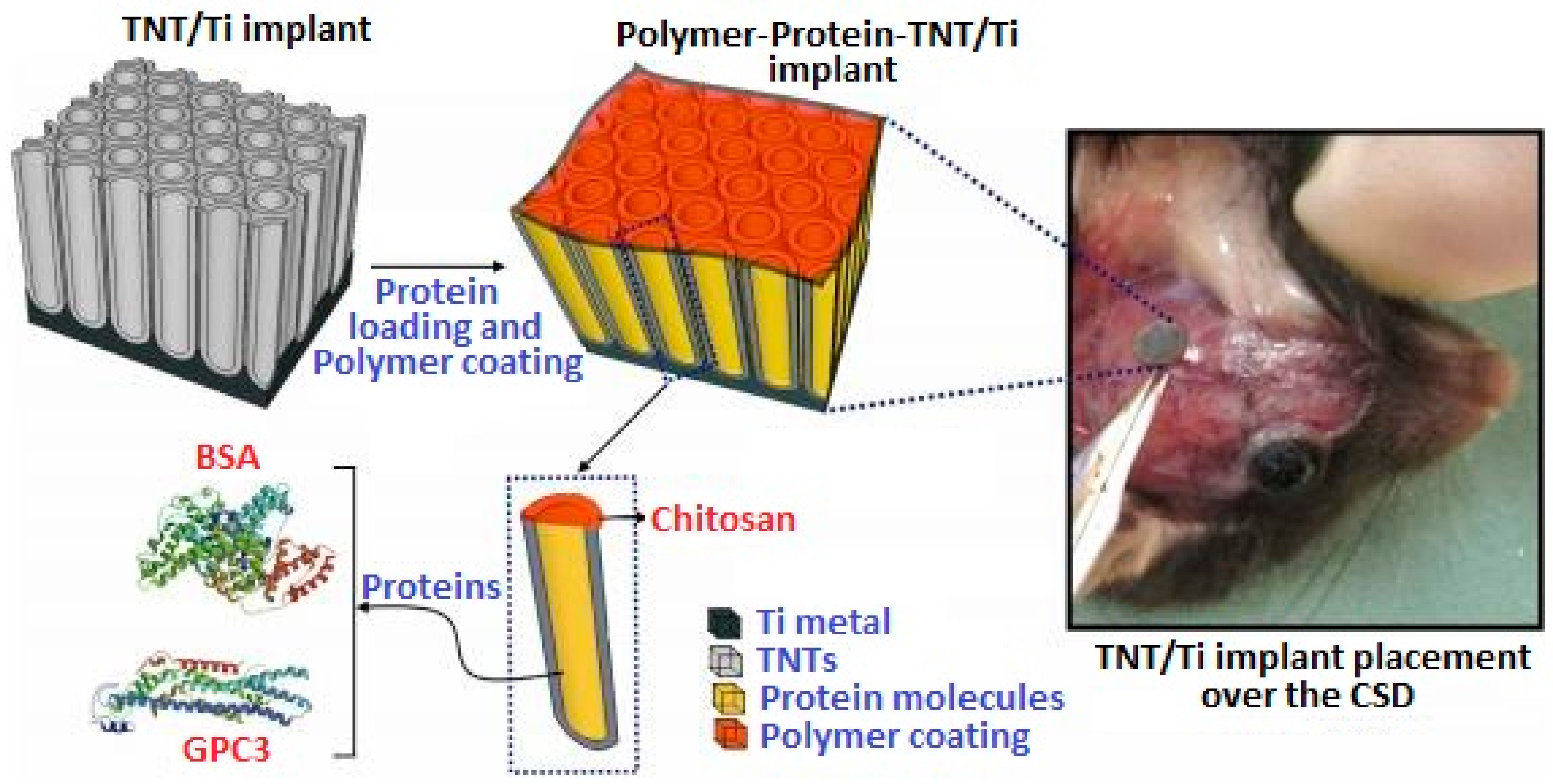
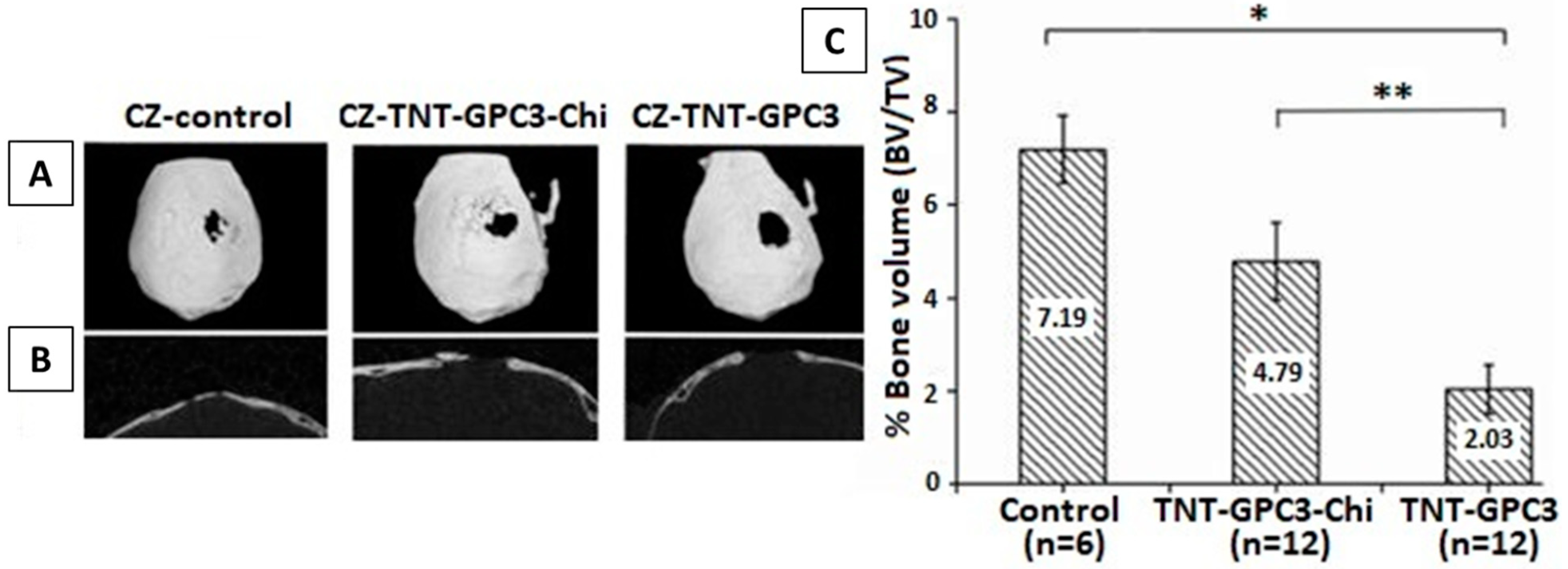
In Vivo Testing of Chi-Based Coatings

After satisfactory results obtained from in vitro testing, in vivo testing is very important to perceive the actual response of the living body towards coated implant materials. For in vivo testing, animals (preferably mice) are used, because they exhibit a close resemblance to humans in terms of genetic, biological, and social behavior. Furthermore, the mice for medical trials are usually inbred (not taken from streets), so their genetic material closely matches humans’ [132]. Other advantages include small size, availability, low cost, and easy handling.
Bariana et al. [133] performed an in vivo rat study to inhibit cranial bone regeneration in rats as a result of developmental disorder during infancy. In this work, Ti with electrochemically grown titania nanotubes (TNTs) was used as a substrate, which was further coated with chi for sustained drug release after loading TNTs with GPC3 drug. Figure 13 represents the schematic of the adopted methodology for the Ti/TNT/chi/GPC3 coating.
Two study models were adopted in this research: a wildtype model (as proof of principle) and Crouzon (CZ) model (as study aim). We will only discuss the CZ model here. In this model, Ti/TNT/GPC3 samples were analyzed in vivo, with and without chi coating. Figure 14A,B shows the top and side view of the cranium with critical-sized defects (CSDs) created surgically, and Figure 14C shows bone volume % around CSDs. Ti/TNT/GPC3 samples displayed significant control over bone regeneration as compared to Ti/TNT/chitosan/GPC3. Still, as compared to the control, both samples with and without chi were able to inhibit the abnormal bone growth.
The above discussion gives a general idea of how chi is being employed in the biomedical field and how it is benefiting society. The main purpose in analyzing biopolymers like chi is to impart beneficial properties (bioactive and antibacterial) to such materials in metallic implants. As EPD is a facile and cost-effective method, and it can be tuned easily by adjusting suspension and process parameters to obtain desired coatings. The recent trend of co-substitution of bioceramics and metallic ion doping has greatly improved the bioactivity and antimicrobial effect of chitosan composite coatings. Still, there are challenges we need to face in terms of mechanical aspects and application of these composite coatings in real-life conditions.

2.5. EPD of Zein Based Coatings

Zein is another natural polymer obtained from plants (specifically from maize/corn). It is a hydrophobic protein, soluble in alcohol, widely used in the food industry and biomedical field [134]. Zein is a hard but flexible material with excellent antibacterial and antioxidant properties [135,136]. As the interest of scientific community has shifted towards finding suitable materials for controlled drug delivery in vivo, zein has emerged as a potential candidate due to its biocompatibility and biodegradability [137]. Extensive research has been carried out on zein and zein-based composites for targeted drug delivery and tissue engineering [138,139]. The amino acids present in zein, such as leucine and proline, are helpful in regulating muscle protein metabolism and enhanced bioactivity of osteoclasts, making it suitable for bone healing applications [83]. Zein is a relatively new polymer to be deposited by EPD as compared to chitosan.
Different zein-based coatings are being developed. In the field of orthopedics, zein is used as coating on SS, Ti, and Mg implants, and as a fixation device [140,141,142]. As discussed in Section 2.4 in case of problems associated with metallic implants (e.g., toxic ion release, corrosion, etc.) and the poor mechanical aspects of zein (being a polymer), it is often mixed with some other components, such as bioceramics (HA, Silica, BG) and antibacterial metal ions (Ag, Sr, Mn, Zn, Cu). The resulting composite not only possesses augmented bioactivity but also provides a very good barrier layer against corrosion and wear for medical devices [143,144,145].
EPD is the most facile and economical coating technique adopted for this purpose [131]. Ramos et al. [83] performed experiments with zein/BG coating on 316L-SS in binary solutions of water and ethanol with varying proportions of both solutes and solvents. The effect of varying voltage and deposition time was also recorded to optimize the process parameters. In conclusion, equal amounts of zein/BG at low voltages were found to result in good-quality coatings.
The mechanism behind the EPD of zein coatings was first investigated by Kaya et al. [84] at various voltages and deposition times on 316L-SS substrate. The EPD mechanism suggested in this work was based on the chemical reactions occurring in acidic environment during deposition. Smooth and homogeneous coatings were obtained, with the highest deposition yield at 10 V for 10 min. The coating was detached from the substrate to infer the self-standing status of the zein coating. The SEM micrograph showing film like coating (A) and digital image of detached film (B) is shown in the Figure 15. As shown, the zein film had no scratch or crack after detaching from substrate.
The drug-carrying ability of biopolymers is a much-explored feature at present. Conventional oral drug administration is not as effective as local drug delivery, which is more efficient and safer [146]. Zein shows capacity as a drug carrier in the particulate form. A study conducted by Muller et al. [147] concluded that the microspheres of zein alone, and also in zein/chi composite form, have ample space for drug loading. The zein/chitosan microparticles were found to be more porous than zein. SEM images of microparticles of zein and zein/chi are shown in Figure 16A,B, along with the Fourier transform infrared (FTIR) spectra of zein, chi, and zein/chi (Figure 16C). The FTIR plot confirms the occurrence of hydrogen bonding between amino groups of zein and chi. Although the authors did not further explore the actual drug loading and subsequent drug release from the microparticles, the mentioned results did confirm the ability of the zein/chi particles to be used for drug carrying applications. This study provides a good direction for future investigations on zein microparticles with other polymers (chi, alginate, gelatin) along with bioceramic particles (BG, HA, silica, CaP glasses). This could add significant knowledge for the scientific community working with biopolymers. These particles can be deposited by EPD over various biocompatible substrates for further research.
For biological applications, it is necessary to analyze the surface of the coating, because it is the surface that comes in contact with the body environment and not the bulk material. Wettability and surface roughness are basic tests conducted to evaluate cellular interaction with coating. As the rough surface provides more sites for cell attachment and proliferation, the wettability study is also important to check how the surface will interact with physiological fluids, because after implantation, fluid is the first thing that comes in contact with the implanted device. Generally, a. contact angle ranging between 35 and 80° is considered suitable [148]. Relevant results for the contact angle were found by Ahmed et al. [85]. The contact angle for zein/HA coating with DI water was measured as 50 ± 2°, which is in the ideal range, as mentioned above. HA incorporated in zein also augmented the hydrophilic capacity of zein coating. The average value for surface roughness was 1 ± 0.1 µm, which is considered good for appropriate interaction with osteoblast-like cells [149].
The bioactivity of zein coating is characterized by its tendency to form an apatite layer on its surface. The apatite formed on the implant has the same chemical composition as naturally found apatite, which is good for enhanced osteoconductivity. This helps to produce strong bonding between the implant surface and living tissues. HA incorporation in zein polymer not only enhances bioactivity but also improves mechanical aspects of the coating [150]. An in vitro bioactivity test in SBF performed by Ahmed et al. [86] for zein/HA coating revealed the formation of HA crystals in the form of cauliflower-like structures on the surface of the coating.
Bioactive coatings impart good antibacterial effects in living bodies. To comprehend the response of zein coatings towards biofilm growth on the surface of the implant, Arango et al. [151] applied a combination of manuka honey (herbal medicine) and zein on 45S5 BG scaffold. Application of honey is an ancient remedy for healing wounds. The antimicrobial and antioxidant effect of honey was imparted to the BG scaffolds along with zein, and the in vitro effect of coated and uncoated samples was tested against Gram-positive S. aureus bacteria. The enhanced antibacterial effect was noted for its coated scaffold. The plot given in Figure 17 exhibits the colony forming unit (CFU) of bacteria vs. time. As seen, significantly lower numbers of bacterial colonies are formed for 20 MH (manuka honey) and zein coating.
Other than SS and Ti, Mg is also a candidate for orthopedic implants due to its high biocompatibility and close elastic modulus to the natural bone [152]. The degradation rate of Mg is high in physiological environment making Mg suitable for temporary implantation devices [119,153]. Biodegradable materials like Mg dissolve in the body under the effect of corrosion with the passage of time and there is no need for second surgery to remove them. But fast degradation rate can result in premature dissolution of implant without fulfilling its purpose. Zein and zein based composite coatings are said to decrease the degradation rate of Mg by forming a protective layer over the metal surface. Atiq et al. [87] deposited zein incorporated with BG particles over pre-treated Mg substrate. EIS was performed to investigate the improved corrosion resistance of Mg substrate after coating with zein/BG. The polarization curves for pure Mg, and coated samples are shown in Figure 18. As the corrosion resistance is inversely related to the current density [154], the plot show that Icorr decreased for zein coating and it was further reduced for zein/BG composite coating. Hence, zein coating was found effective against corrosion of Mg.

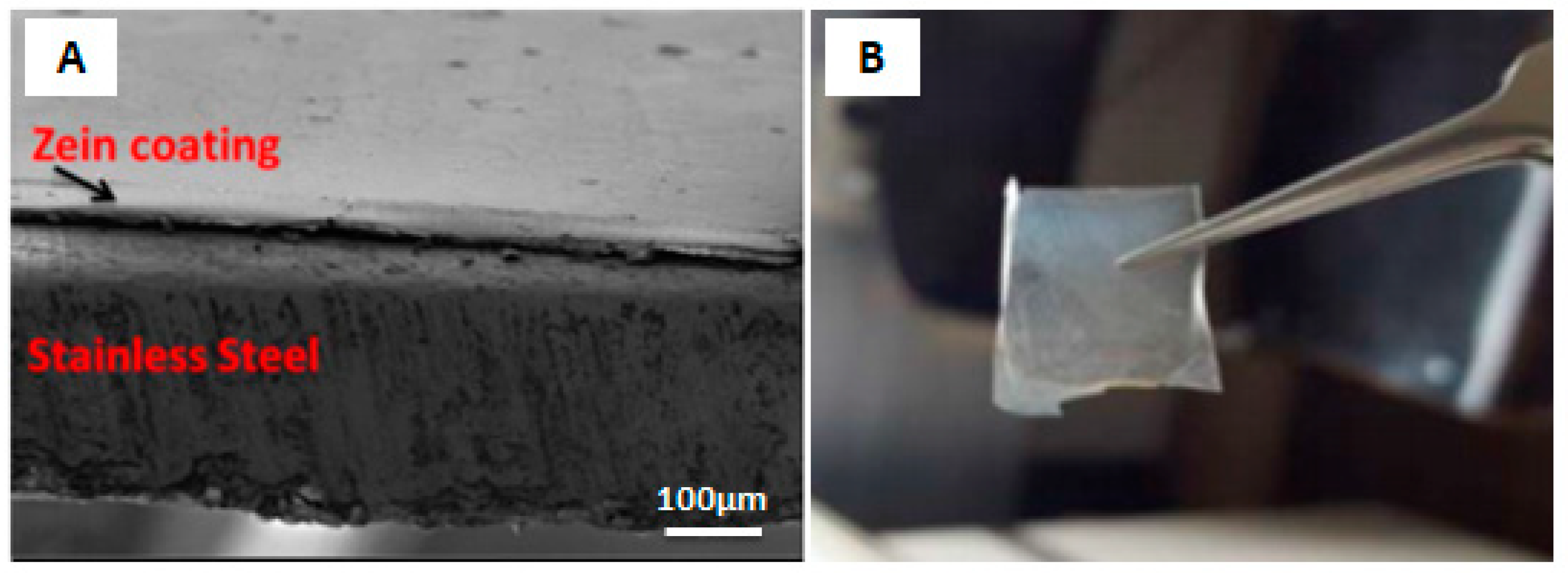
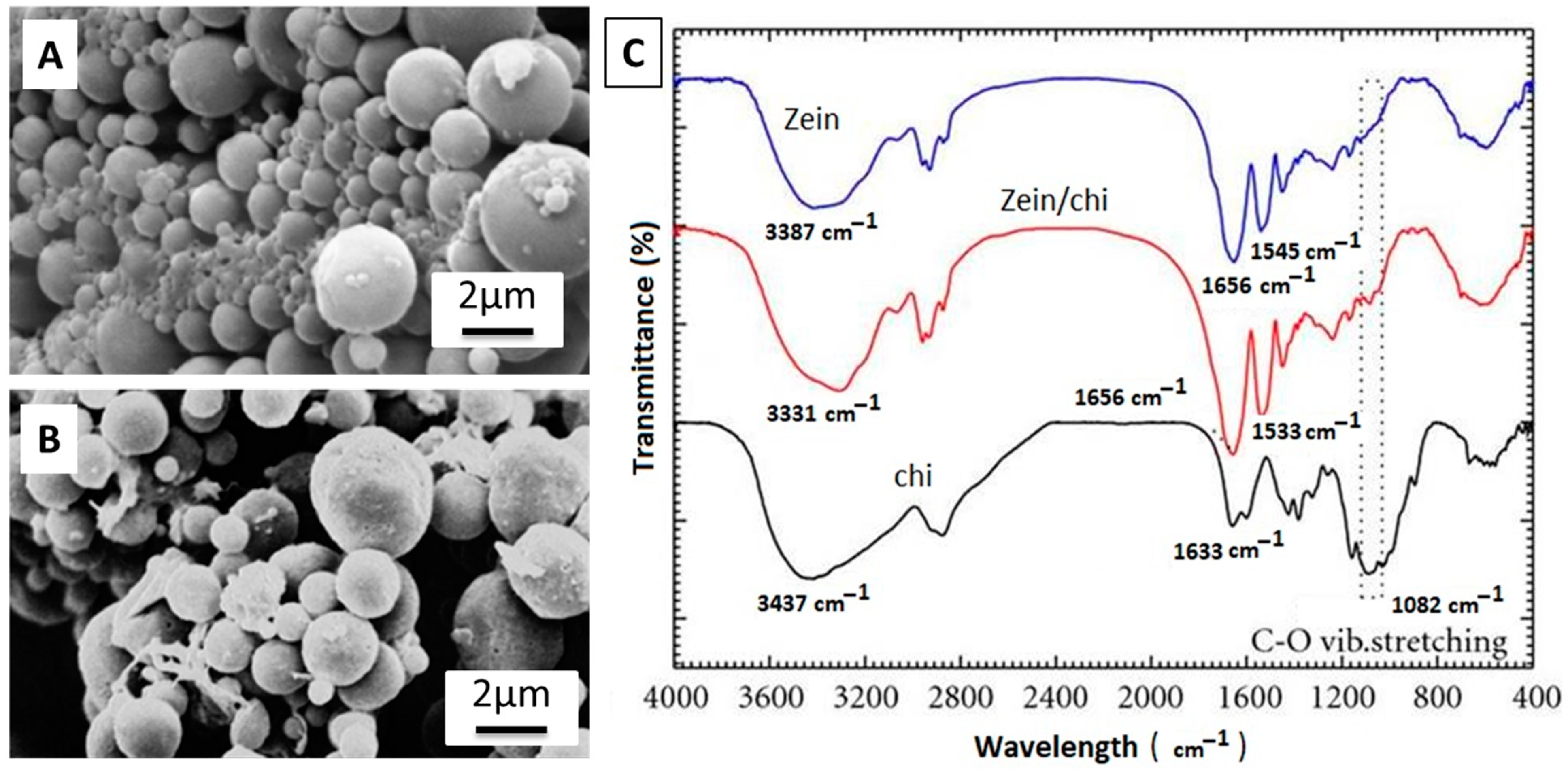
In Vivo Testing of Zein-Based Coating

The in vivo efficiency of zein coatings is a vital aspect to analyze before implementing them in the living environment. An in vivo study performed in a mouse model was put forward by Ramos et al. [88], in which zein/BG/Cu-based coating on 316L-SS was tested for bone healing. At first, in vitro testing was done, which presented satisfactory results for cytocompatibility, osteogenesis, and antibacterial activity. Figure 19 summarizes the in vivo test results. In part A, it was observed that the induced infection in mice was controlled due to Cu incorporation in zein/BG. In Figure 19B, we can see the CFU for zein, zein/BG, and zein/CuBG coatings. In the case of the zein/CuBG coating, no bacterial colonies were present, and for zein and zein/BG coatings, no significant control in bacterial growth was observed. In terms of angiogenesis, zein (Figure 19C–E), zein/BG (Figure 19F–H), and zein/CuBG (Figure 19I–K) coatings all showed the formation of tissues, whereas vessels of about 50–55 μm were formed only in the case of zein/CuBG. Therefore, the results showed that the enhanced angiogenic and antibacterial effect was due to the Cu incorporation and not zein/BG.

2.6. EPD of PEEK Based Coatings

PEEK is a man-made thermoplastic polymer, widely used as biomaterial for orthopedic, trauma, and spinal implants. PEEK comes from the class of polyetherketones, consisting of benzene rings linked by one ketone and two ether functional groups [155]. The stability of PEEK comes from its chemical structure, due to delocalization of its valence electrons through the polymer chain, providing high resistance to all types of degradation mechanisms (i.e., chemical, physical, and thermal) [89]. Owing to these properties, PEEK becomes useful in the insulation of wires and as coating on industrial heat exchangers. PEEK is also compatible with reinforcing agents including ceramics, glasses, and carbon fibers (CFs). The incorporation of the reinforcement particles improves the specific strength and Young’s modulus of PEEK composite materials. PEEK individually has a Young’s modulus of 3–4 GPa, which can be increased up to >18 GPa after incorporating various ceramics and glasses. The improvement in mechanical aspects of PEEK composite materials render it suitable for orthopedic implants [72,156].
One important aspect of PEEK is its degree of crystallinity, which determines its mechanical integrity [90]. PEEK is a semi-crystalline polymer consisting of two phases (i.e., amorphous and crystalline). The degree of crystallinity in PEEK is related to the provided cooling rate after melting. Generally, in slow cooling, the molecular chains get enough time to rotate and reorganize into an ordered structure [91,157,158]. Amorphous PEEK gets crystallized at a glass transition temperature (Tg) of 143 °C. This temperature is well below the melting temperature of PEEK, which is 345 °C [156,159].
The inherent drawbacks related to metallic implants fueled investigations of alternate materials with more biocompatible natures. In the late 1990s, PEEK emerged as a potential replacement for metals, especially in spinal and orthopedic implants [156]. Commercialization of PEEK only started after recognizing its resistance to degradation in various biological environments [156,160]. Moreover, sterilization of PEEK-based implants is possible in a number of environments (UV radiations, gamma radiations) without imparting significant influence on its mechanical integrity [161,162,163].
PEEK is a highly bio-inert polymer; thus, it cannot form a bond with the natural tissues. Nevertheless, PEEK is considered as a safe implant material because it does not react with the human tissues, nor induce any toxic biochemical reaction. The mechanical properties of PEEK are favorable for orthopedic and spinal implants [92]. Here, we present a brief overview of how PEEK and PEEK-based composites have been deposited via EPD for biomedical applications. PEEK alone is a bio-inert material; thus, in order to tune the biological properties, it is important to mix PEEK with bioceramics such as HA, BG, calcium phosphate cements, and so on [93,164]. Furthermore, PEEK is also mixed with alumina, titania, zirconia, graphene (G), carbon nanotubes (CNTs), and h-BN to improve the mechanical integrity of the coatings [89,96,97,98,99,100,101,155,165].
PEEK was first deposited via EPD by Wang et al. [102]. It was observed that uniform films of PEEK can be deposited by varying the deposition voltage and deposition time. However, the challenge is to develop a stable suspension containing PEEK particles. The PEEK-containing suspensions were prepared by using different solvents, for example, ethanol, propanol, and mixture of ethanol and water. One of the best strategies was to disperse PEEK in ethanol at a pH of 6.5.
The preparation of a stable suspension containing multiple particles is a challenging task. The task becomes even more complicated in the presence of PEEK. Thus, forming a uniform deposit from a single suspension containing multiple particles was difficult. However, the scientific community has run a series of experiments to develop stable suspensions for PEEK-based composites, leading to stable suspensions [165,166]. Recently Ur Rehman et al. [94] employed the Taguchi DoE approach to deposited PEEK/BG coatings. It was observed that the PEEK/BG coatings were uniformly deposited by following the deposition parameters and suspension composition suggested by the DoE approach. Figure 20 show that the PEEK/BG particles are uniformly dispersed when applying a deposition voltage of 100–110 V for 120 s of deposition time. Inter-electrode spacing was kept at 5 mm. The results of morphological analysis were found be in good agreement with the DoE results, thus confirming the applicability of the DoE approach in optimizing complex processes.
Similarly, PEEK/GO composite coatings were uniformly deposited via EPD. The solvent was a mixture of propanol and ethanol. The relatively strong ultrasonication allowed a uniform dispersion of PEEK and GO, which resulted in uniform coatings. Figure 21 shows that PEEK was stabilized in the mixture of ethanol and isopropanol by using a tip sonicator. The controlled sonication parameters allowed the deagglomeration of PEEK particles. Afterwards, GO was added to the stabilized PEEK suspension. Uniform coatings were deposited via DC-EPD. The coatings were subsequently dried at 150 °C, and sintered at 380 °C. It was shown that uniform coatings can be obtained by following the scheme presented in Figure 21 [103].
Although the challenge of the deposition of PEEK-based composite coatings was solved through the choice of relevant solvent and tuning deposition parameters, PEEK-based composite coatings require sintering to achieve the appropriate adhesion strength and wettability. The choice of the right sintering temperature requires lot of experimentation (e.g., sintering temperature, sintering time, ramp rate). For example, a recent study has shown that PEEK/BG coatings sintered at 400 °C presented good adhesive strength and bioactivity [93].
PEEK-based composite coatings are mechanically robust while showing improved adhesion strength with the substrate, and better wear and corrosion resistance [167]. For example, PEEK/BG coatings applied on 316L-SS showed an adhesion strength of ~15 N, which is suitable for orthopedic applications [95,104]. The adhesion strength of PEEK composite coatings are attributed to the selection of appropriate sintering temperature and deposition parameters. If the sintering temperature is appropriate (i.e., it allows the molten PEEK pool to cover the substrate completely), this will lead to strong adhesion with the substrate. If the sintering temperature is low and the degree of superheating is not enough to cover the metallic substrate (less fluidity of molten PEEK upon sintering), the embedded ceramic particles will be loosely packed, resulting in poor adhesion with the metallic substrate. In another study, PEEK/graphite coatings showed an adhesion strength of ~23 N. Furthermore, adhesion strength of PEEK coatings was observed to be reduced upon adding graphite. Thus, the second phase must be full covered by PEEK in order to achieve good adhesion with the substrate [105]. PEEK/Si3N4 composite coatings were deposited on Ti alloy, and it was observed that adhesion strength of PEEK (only) coating was better compared to that of the PEEK/Si3N4 composite coatings, as shown in Figure 22 [106]. PEEK/Si3N4 composite coatings showed ~30N adhesion strength, which is very good in terms of biomedical applications. The possible reason for the better adhesion strength achieved may be due the different quality of PEEK used (i.e., PEEK 708X was used in study and many other studies used 704X) [106]. Thus, the particle size of PEEK is important in determining the adhesion strength of the coatings.
A strong barrier is also produced by layers of PEEK-based composite coatings in between the implant surface and physiological environment. As discussed earlier, the selection of appropriate sintering temperature governs the adhesion strength; the case is similar for wear and corrosion resistance, where PEEK-based composite coatings perform as a compliant layer between the substrate and coatings. For example, the corrosion resistance of steel was improved 10-fold through PEEK/BG coating. Figure 23 shows the strong decrease in the current density of the composite coatings in comparison to the bare 316L-SS [93]. This indicates the strong corrosion-resistance behavior of PEEK/BG composite coatings. In another study, it was shown that the PEEK/alumina coatings deposited on Ti alloy also improved the corrosion resistance of substrate material. A possible reason is that the PEEK covers the substrate completely (in the case of optimized sintering and deposition parameters) and acts as a barrier between the physiological environment and substrate. It is important to improve the corrosion resistance of the substrate material in order to inhibit the uncontrolled release of toxic metal ions, which may cause allergy, thus leading to implant loosening and the eventual failure of the implant [89].
In addition to adhesive strength and wear of the coatings, wear resistance of the coating is also important. It is important that the coatings should provide suitable wear resistance when in contact with the natural tissues. Poor wear resistance of the coatings leads to the release of wear debris in the body, which is often very painful for the patients. The combination of PEEK with various ceramic materials is being studied in the literature. It has been reported that PEEK-based composite coatings can improve the wear resistance of the coatings [89,97,107,165]. For example, Virk et al. [107] showed that PEEK/BG composite coatings showed better wear resistance. More interestingly, it was shown that the incorporation of h-BN in the PEEK/BG matrix further improves wear resistance. Furthermore, PEEK also provided the lubrication effect required in the orthopedic joints, which further confirms the suitability of PEEK and PEEK-based composites for biomedical applications.
PEEK and PEEK-based composites are widely employed as biomaterials for various applications, which itself is evidence of the biocompatibility of PEEK-based materials [168]. PEEK, PEEK/OPTIMA (commercialized PEEK polymer), PEEK/BG, and PEEK/CFs have undergone extensive biocompatibility studies, meeting the food and drug administration (FDA)’s criteria [156,168]. No cytotoxic effect of PEEK was indicated in animal studies. However, PEEK exhibits a lack of cellular interaction (inert behavior) in the physiological environment. This effect could be attributed to the high chemical stability of PEEK [168,169]. Furthermore, cell culture studies using fibroblast cells (mouse-derived), osteogenic sarcoma (rat-derived osteoblast cells), and osteoblast cells (human-derived) showed no cytotoxicity of PEEK and PEEK-based composite coatings [162,163,170,171].
As compared to other biopolymers, PEEK is inert in the biological environment, which results in weak bonding between the implant surface and natural tissues or bone [172]. Therefore, extensive research is being conducted to overcome the inertness of PEEK [156,173]. To stimulate bone apposition, PEEK-based bioactive coatings are studied for load-bearing orthopedic applications. PEEK-based bioactive composites were developed by the combination of PEEK with HA, BG, and CaP cements [72,156,174]. Encouraging results were shown by PEEK-based bioactive composites in terms of bioactivity [95,99]. Figure 24 shows that the PEEK-based composite coatings developed needle-like apatite crystals upon immersion in SBF. Furthermore, strong peaks of Ca and P were observed in the EDX analysis, indicating the formation of a new phase on the surface of the coatings. X-ray diffraction (XRD) analysis also confirmed the newly developed phase, which is similar to the HA and FTIR, and confirmed the chemical composition of the newly developed phase, also similar to the HA crystals. Moreover, the PEEK-based bioactive composites have displayed significant improvement in the Young’s modulus [175,176].
Surface modification of PEEK is another strategy to improve the interface of bone and implant. It can be done by wet chemistry or plasma treatment [156]. PEEK coatings with various bioactive incorporations are investigated to achieve the desired bioactivity [177]. Moreover, the controlled level of porosity and surface texture of the implants also improves bone-implant fixation [178].
In order to improve the antibacterial properties of the coatings, various antibacterial agents have been incorporated in the coatings. For example, Seuss et al. [99] added Ag particles in the PEEK/BG composite coatings. In another study, STAC was incorporated in the PEEK/HA composite coatings, and it was observed that the composite coatings can provide a strong antibacterial effect against S. aureus and E. coli [92]. Recently, PEEK-based composite coatings have been further coated with the biodegradable antibacterial layer. The biodegradable layer provided the controlled release of drug/natural herb/metallic ions, thus providing a strong antibacterial effect [78,108,109]. In another strategy, PEEK-based composite coatings were further coated with a silver–silica composite via radio frequency sputtering. The topography of the PEEK-based composite layer allows the antibacterial agent to be stored in the deeper pores of the PEE-based composite. This allows the sustained release of drugs for longer time points and the eventual antibacterial effect. PEEK-based composite coatings are an attractive formulation for targeted drug delivery systems, along with the controlled release of antibacterial agents, owing to the favorable topography of the PEEK-based composite coatings [95,104].

In Vivo Testing of PEEK-Based Coatings

To comprehend the in vivo response of PEEK-based coatings, He et al. [92] prepared a PEEK/G nanocomposite via EPD. The effectiveness of the PEEK/G composite against the growth of tumor cells was analyzed in a mouse model. In this research, the photothermal conversion efficiency of G was utilized for eradication of cancerous cells. The photothermal therapy was conducted for 14 days on a nude mouse. Results suggested that the daily laser treatment based on the PEEK/G composite system effectively inhibited the growth of cancer cells, and the tumor volume was recorded to decrease day by day as shown in Figure 25.

3. Conclusions

In this paper, the fundamental concepts of EPD, including classification, working, key processing parameters, and EPD kinetics and their role in the biomedical field, especially in orthopedics, are discussed. The role of EPD in the polymer coating of chitosan, zein, PEEK, and their respective composite coatings with ceramics (HA, BG, GO, etc.) and metallic ions (Cu, Ag, Sr, Mn, etc.) have been discussed in light of the available literature. The in vitro and in vivo response of these polymer and composite coatings related to biocompatibility, bioactivity, and antibacterial effect, along with their mechanical properties, are addressed in this review. Here, we summarize the conclusive comments and future perspectives for EPD of polymer composite coatings.
EPD is a facile and economical coating technique to process a variety of suspension combinations on a variety of simple and complex substrates. EPD is environmentally friendly. It also provides the ease of manufacturing and high control over the quality of the final product. A deep understanding of the EPD process kinetics and working conditions leads to the efficient fabrication of the intended product.
The biopolymers have good biocompatibility, and they impart bioactiveness to various substrate materials—for example, Ti, which is a biocompatible material, but not bioactive. The polymeric coating on Ti substrate enhances its bioactivity as an implant material, as discussed in Section 2.4 of this review. In light of above discussion, it is evident that not only do the biopolymers render a surface bioactive, but they can also control the degradation rate of a substrate (i.e., in the case of Mg substrate, discussed in Section 2.5.
The challenges still facing the EPD of biopolymers are mostly related to the mechanical aspects of the coatings. Although the incorporation of various metallic ions and ceramics like HA, BG, silicates, and carbon-based materials (CNTs, GO) improve the wear and corrosion resistance of coatings and the recent trend of co-ion doping in MBGNs have augmented the behavior of coatings in real physiological conditions. Still, the adhesion and quality of coatings are not up to the mark, and a lot of research needs to be carried out to optimize the concentration of various elements in the coatings and EPD processing parameters to obtain high-quality coatings for orthopedic implants.

Author Contributions

Conceptualization, S.A.B. and A.W.; methodology, S.W.H.; software, M.Y.; validation, M.A.U.R., S.A.B. and S.W.H.; formal analysis, S.A.B.; investigation, M.A.U.R.; resources, A.W.; data curation, S.A.B.; writing—original draft preparation, S.W.H., A.W., M.A.U.R.; writing—review and editing, A.W.; visualization, M.A.U.R.; supervision, S.W.H.; project administration. All authors have read and agreed to the published version of the manuscript.

Funding

This research received no external funding.

Informed Consent Statement

This is a review article based on previous studies. There is no animal or human experimentation involved in this study.

Conflicts of Interest

The authors declare no conflict of interest.

Abbreviations and Acronyms

2Dtwo-dimensional
3Dthree-dimensional
ACalternating current
BGbioactive glass
CaPcalcium phosphates
CDCconstant direct current
CFscarbon fibers
CFUcolony forming unit
Chichitosan
CNTscarbon nanotubes
CSDscritical sized defects
CTABcetyltrimethyl ammonium bromide
CZCrouzon
DCdirect current
DoEdesign of experiment
DIdeionized
DLVODerjaguin–Landau–Verwy–Overbeek
DMEMDulbecco’s modified eagles medium
EDLelectric double layer
EDXenergy-dispersive X-ray spectroscopy
EISelectrochemical impedance spectroscopy
EMelectrophoretic mobility
EPDelectrophoretic deposition
FDAfood and drug administration
FTIRFourier transform infrared spectroscopy
Ggraphene
GOgraphene oxide
HAhydroxyapatite
h-BNhexagonal boron nitride
LTTlymphocyte transformation testing
MBGNsmesoporous bioactive glass nanoparticles
MHmanuka honey
NPsnanoparticles
OPTIMAcommercialized PEEK polymer
OVATone variable at time
PBSphosphate buffer saline
PDCpulsed direct current
PEEKpolyetheretherketone
SBFsimulated body fluid
SEMscanning electron microscopy
SSstainless steel
STACstearyl-trimethyl-ammonium chloride
TCPtissue culture plate
Tgglass transition temperature
TNTstitania nanotubes
XRDX-ray diffractometry
TKAtotal knee anthroplasty

References

  1. Chiu, W.-H.; Lee, K.-M.; Hsieh, W.-F. High Efficiency Flexible Dye-Sensitized Solar Cells by Multiple Electrophoretic Depositions. J. Power Sources 2011, 196, 3683–3687. [Google Scholar] [CrossRef]
  2. Ferrari, B.; Moreno, R.; Hernán, L.; Melero, M.; Morales, J.; Caballero, A. EPD of Thick Films for Their Application in Lithium Batteries. J. Eur. Ceram. Soc. 2007, 27, 3823–3827. [Google Scholar] [CrossRef]
  3. Ishihara, T.; Sato, K.; Takita, Y. Electrophoretic Deposition of Y2O3-Stabilized ZrO2 Electrolyte Films in Solid Oxide Fuel Cells. J. Am. Ceram. Soc. 1996, 79, 913–919. [Google Scholar] [CrossRef]
  4. Castro, Y.; Ferrari, B.; Moreno, R.; Durán, A. Corrosion Behaviour of Silica Hybrid Coatings Produced from Basic Catalysed Particulate Sols by Dipping and EPD. Surf. Coat. Technol. 2005, 191, 228–235. [Google Scholar] [CrossRef]
  5. Du, C.; Pan, N. Supercapacitors Using Carbon Nanotubes Films by Electrophoretic Deposition. J. Power Sources 2006, 160, 1487–1494. [Google Scholar] [CrossRef]
  6. Farrokhi-Rad, M.; Ghorbani, M. Electrophoretic Deposition of Titania Nanoparticles in Different Alcohols: Kinetics of Deposition. J. Am. Ceram. Soc. 2011, 94, 2354–2361. [Google Scholar] [CrossRef]
  7. Rahighi, R.; Panahi, M.; Akhavan, O.; Mansoorianfar, M. Pressure-Engineered Electrophoretic Deposition for Gentamicin Loading within Osteoblast-Specific Cellulose Nanofiber Scaffolds. Mater. Chem. Phys. 2021, 272, 125018. [Google Scholar] [CrossRef]
  8. Bakhshandeh, S.; Amin Yavari, S. Electrophoretic Deposition: A Versatile Tool against Biomaterial Associated Infections. J. Mater. Chem. B 2018, 6, 1128–1148. [Google Scholar] [CrossRef]
  9. Taale, M.; Krüger, D.; Ossei-Wusu, E.; Schütt, F.; Rehman, M.A.U.; Mishra, Y.K.; Marx, J.; Stock, N.; Fiedler, B.; Boccaccini, A.R. Systematically Designed Periodic Electrophoretic Deposition for Decorating 3D Carbon-Based Scaffolds with Bioactive Nanoparticles. ACS Biomater. Sci. Eng. 2019, 5, 4393–4404. [Google Scholar] [CrossRef]
  10. Arora, D.; Pant, P.; Sharma, P.K. Trends in Functional Biomaterials in Tissue Engineering and Regenerative Medicine BT-Biomaterials in Tissue Engineering and Regenerative Medicine: From Basic Concepts to State of the Art Approaches; Bhaskar, B., Sreenivasa Rao, P., Kasoju, N., Nagarjuna, V., Baadhe, R.R., Eds.; Springer: Singapore, 2021; pp. 215–269. ISBN 978-981-16-0002-9. [Google Scholar]
  11. Li, P.H.; Chu, P.K. 1-Thin Film Deposition Technologies and Processing of Biomaterials; Woodhead Publishing: Sawston, UK, 2016; pp. 3–28. ISBN 978-1-78242-453-6. [Google Scholar]
  12. Singh, S.; Singh, G.; Bala, N. Electrophoretic Deposition of Bioactive Glass Composite Coating on Biomaterials and Electrochemical Behavior Study: A Review. Mater. Today Proc. 2018, 5, 20160–20169. [Google Scholar] [CrossRef]
  13. Hayashi, T.; Takasu, A. Design of Electrophoretic and Biocompatible Poly(2-Oxazoline)s Initiated by Perfluoroalkanesulfoneimides and Electrophoretic Deposition with Bioactive Glass. Biomacromolecules 2015, 16, 1259–1266. [Google Scholar] [CrossRef] [PubMed]
  14. Anné, G.; Vanmeensel, K.; Vleugels, J.; Van der Biest, O. Electrophoretic Deposition as a Novel Near Net Shaping Technique for Functionally Graded Biomaterials. Mater. Sci. Forum 2005, 492–493, 213–218. [Google Scholar] [CrossRef]
  15. Atiq Ur Rehman, M.; Chen, Q.; Braem, A.; Shaffer, M.S.P.; Boccaccini, A.R. Electrophoretic Deposition of Carbon Nanotubes: Recent Progress and Remaining Challenges. Int. Mater. Rev. 2020, 1–30. [Google Scholar] [CrossRef]
  16. Terzyk, A.P.; Zięba, M.; Koter, S.; Korczeniewski, E.; Zięba, W.; Kowalczyk, P.; Kujawa, J. Recent Developments in the Electrophoretic Deposition of Carbon Nanomaterials BT-Porous Materials: Theory and Its Application for Environmental Remediation; Moreno-Piraján, J.C., Giraldo-Gutierrez, L., Gómez-Granados, F., Eds.; Springer International Publishing: Cham, Switzerland, 2021; pp. 113–137. ISBN 978-3-030-65991-2. [Google Scholar]
  17. Hussain, M.; Askari Rizvi, S.H.; Abbas, N.; Sajjad, U.; Shad, M.R.; Badshah, M.A.; Malik, A.I. Recent Developments in Coatings for Orthopedic Metallic Implants. Coatings 2021, 11, 791. [Google Scholar] [CrossRef]
  18. Chen, Q.; Cordero-Arias, L.; Roether, J.A.; Cabanas-Polo, S.; Virtanen, S.; Boccaccini, A.R. Alginate/Bioglass® Composite Coatings on Stainless Steel Deposited by Direct Current and Alternating Current Electrophoretic Deposition. Surf. Coat. Technol. 2013, 233, 49–56. [Google Scholar] [CrossRef]
  19. Neirinck, B.; Fransaer, J.; Van der Biest, O.; Vleugels, J. Aqueous Electrophoretic Deposition in Asymmetric AC Electric Fields (AC–EPD). Electrochem. Commun. 2009, 11, 57–60. [Google Scholar] [CrossRef]
  20. Nawrotek, K.; Grams, J. Understanding Electrodeposition of Chitosan–Hydroxyapatite Structures for Regeneration of Tubular-Shaped Tissues and Organs. Materials 2021, 14, 1288. [Google Scholar] [CrossRef]
  21. Neirinck, B.; Mellaert, L.; Fransaer, J.; Van der Biest, O.; Anné, J.; Vleugels, J. Electrophoretic Deposition of Bacterial Cells. Electrochem. Commun. 2009, 11, 1842–1845. [Google Scholar] [CrossRef]
  22. Altomare, L.; Bonetti, L.; Campiglio, C.E.; De Nardo, L.; Draghi, L.; Tana, F.; Farè, S. Biopolymer-Based Strategies in the Design of Smart Medical Devices and Artificial Organs. Int. J. Artif. Organs 2018, 41, 337–359. [Google Scholar] [CrossRef] [Green Version]
  23. Miola, M.; Verné, E.; Ciraldo, F.E.; Cordero-Arias, L.; Boccaccini, A.R. Electrophoretic Deposition of Chitosan/45S5 Bioactive Glass Composite Coatings Doped with Zn and Sr. Front. Bioeng. Biotechnol. 2015, 3, 159. [Google Scholar] [CrossRef] [Green Version]
  24. Seuss, S.; Boccaccini, A.R. Electrophoretic Deposition of Biological Macromolecules, Drugs, and Cells. Biomacromolecules 2013, 14, 3355–3369. [Google Scholar] [CrossRef] [PubMed]
  25. Shadjou, N.; Hasanzadeh, M. Silica-Based Mesoporous Nanobiomaterials as Promoter of Bone Regeneration Process. J. Biomed. Mater. Res. Part A 2015, 103, 3703–3716. [Google Scholar] [CrossRef] [PubMed]
  26. Deraine, A.; Rebelo Calejo, M.T.; Agniel, R.; Kellomäki, M.; Pauthe, E.; Boissière, M.; Massera, J. Polymer-Based Honeycomb Films on Bioactive Glass: Toward a Biphasic Material for Bone Tissue Engineering Applications. ACS Appl. Mater. Interfaces 2021, 13, 29984–29995. [Google Scholar] [CrossRef]
  27. Sikkema, R.; Baker, K.; Zhitomirsky, I. Electrophoretic Deposition of Polymers and Proteins for Biomedical Applications. Adv. Colloid Interface Sci. 2020, 284, 102272. [Google Scholar] [CrossRef] [PubMed]
  28. Moskalewicz, T.; Warcaba, M.; Cieniek, Ł.; Sitarz, M.; Gajewska, M.; Boccaccini, A.R. Hydroxyapatite/Sodium Alginate Coatings Electrophoretically Deposited on Titanium Substrates: Microstructure and Properties. Appl. Surf. Sci. 2021, 540, 148353. [Google Scholar] [CrossRef]
  29. Ducheyne, P.; Van Raemdonck, W.; Heughebaert, J.C.; Heughebaert, M. Structural Analysis of Hydroxyapatite Coatings on Titanium. Biomaterials 1986, 7, 97–103. [Google Scholar] [CrossRef]
  30. Naghdi, S.; Jaleh, B.; Ehsani, A. Electrophoretic Deposition of Graphene Oxide on Aluminum: Characterization, Low Thermal Annealing, Surface and Anticorrosive Properties. Bull. Chem. Soc. Jpn. 2015, 88, 722–728. [Google Scholar] [CrossRef]
  31. Naghdi, S.; Jaleh, B.; Shahbazi, N. Reversible Wettability Conversion of Electrodeposited Graphene Oxide/Titania Nanocomposite Coating: Investigation of Surface Structures. Appl. Surf. Sci. 2016, 368, 409–416. [Google Scholar] [CrossRef]
  32. Omidi, M.; Fatehinya, A.; Farahani, M.; Akbari, Z.; Shahmoradi, S.; Yazdian, F.; Tahriri, M.; Moharamzadeh, K.; Tayebi, L.; Vashaee, D. Characterization of biomaterials. In Biomaterials for Oral and Dental Tissue Engineering; Woodhead Publishing: Sawston, UK, 2017; pp. 97–115. ISBN 9780081009611. [Google Scholar]
  33. Sampath Kumar, T.S. Chapter 2-Physical and Chemical Characterization of Biomaterials; Bandyopadhyay, A., Bose, S., Eds.; Academic Press: Oxford, UK, 2013; pp. 11–47. ISBN 978-0-12-415800-9. [Google Scholar]
  34. Roeder, R.K. Chapter 3-Mechanical Characterization of Biomaterials; Bandyopadhyay, A., Bose, S., Eds.; Academic Press: Oxford, UK, 2013; pp. 49–104. ISBN 978-0-12-415800-9. [Google Scholar]
  35. Thasneem, Y.M.; Sharma, C.P. Chapter 5.1-In Vitro Characterization of Cell–Biomaterials Interactions; Academic Press: Oxford, UK, 2013; pp. 175–205. ISBN 978-0-12-415800-9. [Google Scholar]
  36. Jahanmard, F.; Dijkmans, F.M.; Majed, A.; Vogely, H.C.; van der Wal, B.C.H.; Stapels, D.A.C.; Ahmadi, S.M.; Vermonden, T.; Amin Yavari, S. Toward Antibacterial Coatings for Personalized Implants. ACS Biomater. Sci. Eng. 2020, 6, 5486–5492. [Google Scholar] [CrossRef]
  37. Mitra, D.; Kang, E.-T.; Neoh, K.G. Polymer-Based Coatings with Integrated Antifouling and Bactericidal Properties for Targeted Biomedical Applications. ACS Appl. Polym. Mater. 2021, 3, 2233–2263. [Google Scholar] [CrossRef]
  38. Song, J.; Chen, Q.; Zhang, Y.; Diba, M.; Kolwijck, E.; Shao, J.; Jansen, J.A.; Yang, F.; Boccaccini, A.R.; Leeuwenburgh, S.C.G. Electrophoretic Deposition of Chitosan Coatings Modified with Gelatin Nanospheres to Tune the Release of Antibiotics. ACS Appl. Mater. Interfaces 2016, 8, 13785–13792. [Google Scholar] [CrossRef] [PubMed]
  39. Barrett, D.J.; Linley, M.D.; Best, S.M.; Cameron, R.E. Fabrication of Free Standing Collagen Membranes by Pulsed-Electrophoretic Deposition. Biofabrication 2019, 11, 45017. [Google Scholar] [CrossRef] [PubMed]
  40. Clifford, A.; Luo, D.; Zhitomirsky, I. Colloidal Strategies for Electrophoretic Deposition of Organic-Inorganic Composites for Biomedical Applications. Colloids Surf. Physicochem. Eng. Asp. 2017, 516, 219–225. [Google Scholar] [CrossRef]
  41. Besra, L.; Liu, M. A Review on Fundamentals and Applications of Electrophoretic Deposition (EPD). Prog. Mater. Sci. 2007, 52, 1–61. [Google Scholar] [CrossRef]
  42. Boccaccini, A.R.; Keim, S.; Ma, R.; Li, Y.; Zhitomirsky, I. Electrophoretic Deposition of Biomaterials. J. R. Soc. Interface 2010, 7 (Suppl. 5), S581–S613. [Google Scholar] [CrossRef] [Green Version]
  43. Ammam, M. Electrophoretic Deposition under Modulated Electric Fields: A Review. RSC Adv. 2012, 2, 7633–7646. [Google Scholar] [CrossRef]
  44. Chávez-Valdez, A.; Boccaccini, A.R. Innovations in Electrophoretic Deposition: Alternating Current and Pulsed Direct Current Methods. Electrochim. Acta 2012, 65, 70–89. [Google Scholar] [CrossRef]
  45. Hu, X.; Bessette, P.H.; Qian, J.; Meinhart, C.D.; Daugherty, P.S.; Soh, H.T. Marker-Specific Sorting of Rare Cells Using Dielectrophoresis. Proc. Natl. Acad. Sci. USA 2005, 102, 15757–15761. [Google Scholar] [CrossRef] [Green Version]
  46. Novak, S.; Maver, U.; Peternel, Š.; Venturini, P.; Bele, M.; Gaberšček, M. Electrophoretic Deposition as a Tool for Separation of Protein Inclusion Bodies from Host Bacteria in Suspension. Colloids Surf. Physicochem. Eng. Asp. 2009, 340, 155–160. [Google Scholar] [CrossRef]
  47. Aliofkhazraei, M.; Makhlouf, A.S.H. Handbook of Nanoelectrochemistry: Electrochemical Synthesis Methods, Properties, and Characterization Techniques; Springer: New York, NY, USA, 2016; ISBN 9783319152660. [Google Scholar]
  48. Ohshima, H. (Ed.) Chapter 8-Electrokinetic phenomena in a suspension of liquid drops. In Theory of Colloid and Interfacial Electric Phenomena; Elsevier: Amsterdam, The Netherlands, 2006; Volume 12, pp. 182–202. ISBN 1573-4285. [Google Scholar]
  49. Talebi, T.; Ghomashchi, R.; Talemi, P.; Aminorroaya, S. Suspension Characteristics and Electrophoretic Deposition Ofp-Type Bi2Te3Films for Thermoelectric Applications. J. Electrochem. Soc. 2018, 165, D364–D369. [Google Scholar] [CrossRef]
  50. LASKA, A. Parameters of the Electrophoretic Deposition Process and Its Influence on the Morphology of Hydroxyapatite Coatings. Review. Inżynieria Mater. 2020, 1, 20–25. [Google Scholar] [CrossRef]
  51. Kang, H.; Park, Y.; Hong, Y.-K.; Yoon, S.; Lee, M.-H.; Ha, D.-H. Solvent-Induced Charge Formation and Electrophoretic Deposition of Colloidal Iron Oxide Nanoparticles. Surf. Interfaces 2021, 22, 100815. [Google Scholar] [CrossRef]
  52. Malvern Instruments. Zeta Potential: An Introduction in 30 Minutes. Zetasizer Nano Serles Tech. Note MRK654-01 2011, 2, 1–6. [Google Scholar]
  53. Boccaccini, A.R.; Cho, J.; Roether, J.A.; Thomas, B.J.C.; Jane Minay, E.; Shaffer, M.S.P. Electrophoretic Deposition of Carbon Nanotubes. Carbon N. Y. 2006, 44, 3149–3160. [Google Scholar] [CrossRef]
  54. Freitas, C.; Müller, R.H. Effect of Light and Temperature on Zeta Potential and Physical Stability in Solid Lipid Nanoparticle (SLNTM) Dispersions. Int. J. Pharm. 1998, 168, 221–229. [Google Scholar] [CrossRef]
  55. Marín-Suárez, M.; Medina-Rodríguez, S.; Ergeneman, O.; Pané, S.; Fernández-Sánchez, J.F.; Nelson, B.J.; Fernández-Gutiérrez, A. Electrophoretic Deposition as a New Approach to Produce Optical Sensing Films Adaptable to Microdevices. Nanoscale 2014, 6, 263–271. [Google Scholar] [CrossRef] [PubMed] [Green Version]
  56. Sadeghi, A.A.; Ebadzadeh, T.; Raissi, B.; Ghashghaie, S. Electrophoretic Deposition of TiO2 Nanoparticles in Viscous Alcoholic Media. Ceram. Int. 2013, 39, 7433–7438. [Google Scholar] [CrossRef]
  57. Vineetha, P. Fabrication of Dielectric Thick Films by Electrophoretic Deposition and Their Characterization; IntechOpen: Rijeka, Yugoslavia, 2020; ISBN 978-1-78984-687-4. [Google Scholar]
  58. Bintou, O.; Savadogo, O. Electrophoretic Deposition of Alumina and Nickel Oxide Particles. Ournal Sci. Res. Rep. 2013, 2, 190–205. [Google Scholar] [CrossRef]
  59. Kwok, C.T.; Wong, P.K.; Cheng, F.T.; Man, H.C. Characterization and Corrosion Behavior of Hydroxyapatite Coatings on Ti6Al4V Fabricated by Electrophoretic Deposition. Appl. Surf. Sci. 2009, 255, 6736–6744. [Google Scholar] [CrossRef]
  60. Boccaccini, A.R.; Schindler, U.; Krüger, H.-G. Ceramic Coatings on Carbon and Metallic Fibres by Electrophoretic Deposition. Mater. Lett. 2001, 51, 225–230. [Google Scholar] [CrossRef]
  61. Abdeltawab, A.A.; Shoeib, M.A.; Mohamed, S.G. Electrophoretic Deposition of Hydroxyapatite Coatings on Titanium from Dimethylformamide Suspensions. Surf. Coat. Technol. 2011, 206, 43–50. [Google Scholar] [CrossRef]
  62. Albayrak, O.; El-Atwani, O.; Altintas, S. Hydroxyapatite Coating on Titanium Substrate by Electrophoretic Deposition Method: Effects of Titanium Dioxide Inner Layer on Adhesion Strength and Hydroxyapatite Decomposition. Surf. Coat. Technol. 2008, 202, 2482–2487. [Google Scholar] [CrossRef]
  63. Zhao, P.; Lesergent, L.J.; Farnese, J.; Wen, J.Z.; Ren, C.L. Electrochemistry Communications Electrophoretic Deposition of Carbon Nanotubes on Semi-Conducting and Non-Conducting Substrates. Electrochem. Commun. 2019, 108, 106558. [Google Scholar] [CrossRef]
  64. Pishbin, F.; Simchi, A.; Ryan, M.P.; Boccaccini, A.R. Electrophoretic Deposition of Chitosan/45S5 Bioglass® Composite Coatings for Orthopaedic Applications. Surf. Coat. Technol. 2011, 205, 5260–5268. [Google Scholar] [CrossRef]
  65. Mosconi, D.; Giovannini, G.; Maccaferri, N.; Serri, M.; Agnoli, S.; Garoli, D. Electrophoretic Deposition of WS(2) Flakes on Nanoholes Arrays-Role of Used Suspension Medium. Materials 2019, 12, 3286. [Google Scholar] [CrossRef] [Green Version]
  66. Hamaker, H.C. Formation of a Deposit by Electrophoresis. Trans. Faraday Soc. 1940, 35, 279–287. [Google Scholar] [CrossRef]
  67. Ferrari, B.; Moreno, R. EPD Kinetics: A Review. J. Eur. Ceram. Soc. 2010, 30, 1069–1078. [Google Scholar] [CrossRef]
  68. Sarkar, P.; Nicholson, P.P.S. Electrophoretic Deposition (EPD): Mechanisms, Kinetics and Application to Ceramics; Wiley-Blackwell: New York, NY, USA, 1996; Volume 79, pp. 1987–2002. [Google Scholar]
  69. Biesheuvel, P.M.; Verweij, H. Theory of Cast Formation in Electrophoretic Deposition. J. Am. Ceram. Soc. 1999, 82, 1451–1455. [Google Scholar] [CrossRef]
  70. Anné, G.; Vanmeensel, K.; Vleugels, J.; Van der Biest, O. A Mathematical Description of the Kinetics of the Electrophoretic Deposition Process for Al2O3-Based Suspensions. J. Am. Ceram. Soc. 2005, 88, 2036–2039. [Google Scholar] [CrossRef]
  71. Fukada, Y.; Nagarajan, N.; Mekky, W.; Bao, Y.; Kim, H.; Nicholson, P. Electrophoretic Deposition—Mechanisms, Myths and Materials. J. Mater. Sci. 2004, 39, 787–801. [Google Scholar] [CrossRef]
  72. Heise, S.; Virtanen, S.; Boccaccini, A.R. Taguchi Design of Experiments Approach to Determine Process Parameter for the Electrophoretic Deposition of Chitosan / Bioactive Glass on Mg Alloy Substrates. Electrochem. Soc. Tras 2018, 82, 81–87. [Google Scholar] [CrossRef]
  73. Pishbin, F.; Mouriño, V.; Gilchrist, J.B.; McComb, D.W.; Kreppel, S.; Salih, V.; Ryan, M.P.; Boccaccini, A.R. Single-Step Electrochemical Deposition of Antimicrobial Orthopaedic Coatings Based on a Bioactive Glass/Chitosan/Nano-Silver Composite System. Acta Biomater. 2013, 9, 7469–7479. [Google Scholar] [CrossRef] [PubMed]
  74. Rehman, M.A.U.; Bastan, F.E.; Nawaz, Q.; Boccaccini, A.R.; Atiq, M.; Rehman, U.; Bastan, F.E.; Nawaz, Q.; Boccaccini, A.R.; Rehman, M.A.U.; et al. Electrophoretic Deposition of Lawsone Loaded Nanoscale Silicate Glass/Chitosan Composite on PEEK/BG Layers. Electrochem. Soc. Tras 2018, 82, 45–50. [Google Scholar] [CrossRef]
  75. Aqib, R. Ag–Sr Doped Mesoporous Bioactive Glass Nanoparticles Loaded Chitosan/Gelatin Coating for Orthopedic Implants. Int. J. Appl. Ceram. Technol. 2021, 18, 544–562. [Google Scholar] [CrossRef]
  76. Aydemir, T.; Liverani, L.; Pastore, J.I.; Ceré, S.M.; Goldmann, W.H.; Boccaccini, A.R.; Ballarre, J. Functional Behavior of Chitosan/Gelatin/Silica-Gentamicin Coatings by Electrophoretic Deposition on Surgical Grade Stainless Steel. Mater. Sci. Eng. C 2020, 115, 111062. [Google Scholar] [CrossRef]
  77. Saleem, O.; Wahaj, M.; Akhtar, M.A.; Ur Rehman, M.A. Fabrication and Characterization of Ag–Sr-Substituted Hydroxyapatite/Chitosan Coatings Deposited via Electrophoretic Deposition: A Design of Experiment Study. ACS Omega 2020, 5, 22984–22992. [Google Scholar] [CrossRef] [PubMed]
  78. Nawaz, A.; Bano, S.S.S.; Yasir, M.; Wadood, A.; Ur Rehman, M.A.; Rehman, M.A.U. Ag and Mn-Doped Mesoporous Bioactive Glass Nanoparticles Incorporated into the Chitosan/Gelatin Coatings Deposited on PEEK/Bioactive Glass Layers for Favorable Osteogenic Differentiation and Antibacterial Activity. Mater. Adv. 2020, 1, 1273–1284. [Google Scholar] [CrossRef]
  79. Pishbin, F.; Mouriño, V.; Flor, S.; Kreppel, S.; Salih, V.; Ryan, M.P.; Boccaccini, A.R. Electrophoretic Deposition of Gentamicin-Loaded Bioactive Glass/Chitosan Composite Coatings for Orthopaedic Implants. ACS Appl. Mater. Interfaces 2014, 6, 8796–8806. [Google Scholar] [CrossRef]
  80. Gebhardt, F.; Seuss, S.; Turhan, M.C.; Hornberger, H.; Virtanen, S.; Boccaccini, A.R. Characterization of Electrophoretic Chitosan Coatings on Stainless Steel. Mater. Lett. 2012, 66, 302–304. [Google Scholar] [CrossRef]
  81. Agata, S.; Heise, S.; Topolski, K.; Garbacz, H.; Boccaccini, A.R. Chitosan/Bioactive Glass Coatings as a Protective Layer against Corrosion of Nanocrystalline Titanium under Simulated Inflammation. Mater. Lett. 2020, 264, 127284. [Google Scholar] [CrossRef]
  82. Szklarska, M.; Łosiewicz, B.; Dercz, G.; Maszybrocka, J.; Rams-Baron, M.; Stach, S. Electrophoretic Deposition of Chitosan Coatings on the Ti15Mo Biomedical Alloy from a Citric Acid Solution. RSC Adv. 2020, 10, 13386–13393. [Google Scholar] [CrossRef] [Green Version]
  83. Ramos Rivera, L.; Dippel, J.; Boccaccini, A.R. Formation of Zein/Bioactive Glass Layers Using Electrophoretic Deposition Technique. ECS Trans. 2018, 82, 73–80. [Google Scholar] [CrossRef]
  84. Kaya, S.; Boccaccini, A.R. Electrophoretic Deposition of Zein Coatings. J. Coat. Technol. Res. 2017, 14, 683–689. [Google Scholar] [CrossRef]
  85. Ahmed, Y.; Yasir, M.; Ur Rehman, M.A. Fabrication and Characterization of Zein/Hydroxyapatite Composite Coatings for Biomedical Applications. Surfaces 2020, 3, 237–250. [Google Scholar] [CrossRef]
  86. Ahmed, Y.; Rehman, M.A.U. Improvement in the Surface Properties of Stainless Steel via Zein/Hydroxyapatite Composite Coatings for Biomedical Applications. Surf. Interfaces 2020, 20, 100589. [Google Scholar] [CrossRef]
  87. Rehman, U.; Atiq, M. Zein/Bioactive Glass Coatings with Controlled Degradation of Magnesium under Physiological Conditions: Designed for Orthopedic Implants. Prosthesis 2020, 2, 211–224. [Google Scholar] [CrossRef]
  88. Ramos, L.; Cochis, A.; Biser, S.; Canciani, E.; Ferraris, S.; Rimondini, L.; Boccaccini, A.R. Bioactive Materials Copper Based Coatings for Implantable Stainless Steel Aimed at Bone Healing. Bioact. Mater. 2021, 6, 1479–1490. [Google Scholar] [CrossRef]
  89. Moskalewicz, T.; Zimowski, S.; Zych, A.; Łukaszczyk, A.; Reczyńska, K.; Pamuła, E. Electrophoretic Deposition, Microstructure and Selected Properties of Composite Alumina/Polyetheretherketone Coatings on the Ti-13Nb-13Zr Alloy. J. Electrochem. Soc. 2018, 165, D116–D128. [Google Scholar] [CrossRef] [Green Version]
  90. Boccaccini, A.R.; Peters, C.; Roether, J.A.; Eifler, D.; Misra, S.K.; Minay, E.J. Electrophoretic Deposition of Polyetheretherketone (PEEK) and PEEK/Bioglass® Coatings on NiTi Shape Memory Alloy Wires. J. Mater. Sci. 2006, 41, 8152–8159. [Google Scholar] [CrossRef]
  91. Iveković, A.; Novak, S.; Lukek, M.; Kalin, M. Aqueous Electrophoretic Deposition of Bulk Polyether Ether Ketone (PEEK). J. Mater. Process. Technol. 2015, 223, 58–64. [Google Scholar] [CrossRef]
  92. He, M.; Zhu, C.; Xu, H.; Sun, D.; Chen, C.; Feng, G.; Liu, L.; Li, Y.; Zhang, L. Conducting Polyetheretherketone Nanocomposites with an Electrophoretically Deposited Bioactive Coating for Bone Tissue Regeneration and Multimodal Therapeutic Applications. ACS Appl. Mater. Interfaces 2020, 12, 56924–56934. [Google Scholar] [CrossRef]
  93. Ur Rehman, M.A.; Bastan, F.E.; Nawaz, A.; Nawaz, Q.; Wadood, A.; Rehman, M.A.U.; Bastan, F.E.; Nawaz, A.; Nawaz, Q.; Wadood, A. Electrophoretic Deposition of PEEK/Bioactive Glass Composite Coatings on Stainless Steel for Orthopedic Applications: An Optimization for in Vitro Bioactivity and Adhesion Strength. Int. J. Adv. Manuf. Technol. 2020, 108, 1849–1862. [Google Scholar] [CrossRef]
  94. Atiq Ur Rehman, M.; Bastan, F.E.; Haider, B.; Boccaccini, A.R.; Rehman, M.A.U.; Bastan, F.E.; Haider, B.; Boccaccini, A.R. Electrophoretic Deposition of PEEK/Bioactive Glass Composite Coatings for Orthopedic Implants: A Design of Experiments (DoE) Study. Mater. Des. 2017, 130, 223–230. [Google Scholar] [CrossRef]
  95. Ur Rehman, M.A.; Ferraris, S.; Goldmann, W.H.; Perero, S.; Bastan, F.E.; Nawaz, Q.; Di Confiengo, G.G.; Ferraris, M.; Boccaccini, A.R. Antibacterial and Bioactive Coatings Based on Radio Frequency Co-Sputtering of Silver Nanocluster-Silica Coatings on PEEK/Bioactive Glass Layers Obtained by Electrophoretic Deposition. ACS Appl. Mater. Interfaces 2017, 9, 32489–32497. [Google Scholar] [CrossRef] [PubMed]
  96. Moskalewicz, T.; Zimowski, S.; Fiołek, A.; Łukaszczyk, A.; Dubiel, B.; Cieniek, Ł. The Effect of the Polymer Structure in Composite Alumina / Polyetheretherketone Coatings on Corrosion Resistance, Micro-Mechanical and Tribological Properties of the Ti-6Al-4V Alloy. J. Mater. Eng. Perform. 2020, 29, 1426–1438. [Google Scholar] [CrossRef] [Green Version]
  97. Sak, A.; Moskalewicz, T.; Zimowski, S.; Cieniek, Ł.; Dubiel, B.; Radziszewska, A.; Kot, M.; Łukaszczyk, A. Influence of Polyetheretherketone Coatings on the Ti-13Nb-13Zr Titanium Alloy’s Bio-Tribological Properties and Corrosion Resistance. Mater. Sci. Eng. C 2016, 63, 52–61. [Google Scholar] [CrossRef]
  98. Moskalewicz, T.; Zych, A.; Kruk, A.; Kopia, A.; Zimowski, S.; Sitarz, M.; Cieniek, Ł. Electrophoretic Deposition and Microstructure Development of Si3N4/Polyetheretherketone Coatings on Titanium Alloy. Surf. Coat. Technol. 2018, 350, 633–647. [Google Scholar] [CrossRef]
  99. Seuss, S.; Heinloth, M.; Boccaccini, A.R. Development of Bioactive Composite Coatings Based on Combination of PEEK, Bioactive Glass and Ag Nanoparticles with Antibacterial Properties. Surf. Coat. Technol. 2015, 301, 100–105. [Google Scholar] [CrossRef]
  100. Virk, R.S.; Rehman, M.A.U.; Boccaccini, A.R. PEEK Based Biocompatible Coatings Incorporating H-BN and Bioactive Glass by Electrophoretic Deposition. ECS Trans. 2018, 82, 89–95. [Google Scholar] [CrossRef]
  101. Seuss, S.; Subhani, T.; Kang, M.Y.; Okudaira, K.; Aguilar Ventura, I.E.; Boccaccini, A.R. Electrophoretic Deposition of PEEK-TiO2 Composite Coatings on Stainless Steel. Key Eng. Mater. 2012, 507, 127–133. [Google Scholar] [CrossRef]
  102. Wang, C.; Ma, J.; Cheng, W. Formation of Polyetheretherketone Polymer Coating by Electrophoretic Deposition Method. Surf. Coat. Technol. 2003, 173, 271–275. [Google Scholar] [CrossRef]
  103. González-Castillo, E.I.; Costantini, T.; Shaffer, M.S.P.; Boccaccini, A.R. Nanocomposite Coatings Obtained by Electrophoretic Co-Deposition of Poly (Etheretherketone)/Graphene Oxide Suspensions. J. Mater. Sci. 2020, 55, 8881–8899. [Google Scholar] [CrossRef]
  104. Nawaz, Q.; Fastner, S.; Rehman, M.A.U.; Ferraris, S.; Perero, S.; Di Confiengo, G.G.; Yavuz, E.; Ferraris, M.; Boccaccini, A.R. Multifunctional Stratified Composite Coatings by Electrophoretic Deposition and RF Co-Sputtering for Orthopaedic Implants. J. Mater. Sci. 2021, 56, 7920–7935. [Google Scholar] [CrossRef]
  105. Fiołek, A.; Zimowski, S.; Kopia, A.; Łukaszczyk, A.; Moskalewicz, T. Electrophoretic Co-Deposition of Polyetheretherketone and Graphite Particles: Microstructure, Electrochemical Corrosion Resistance, and Coating Adhesion to a Titanium Alloy. Materials 2020, 13, 3251. [Google Scholar] [CrossRef] [PubMed]
  106. Fiołek, A.; Zimowski, S.; Kopia, A.; Moskalewicz, T. The Influence of Electrophoretic Deposition Parameters and Heat Treatment on the Microstructure and Tribological Properties of Nanocomposite Si3N4/PEEK 708 Coatings on Titanium Alloy. Coatings 2019, 9, 530. [Google Scholar] [CrossRef] [Green Version]
  107. Virk, R.S.; Atiq, M.; Rehman, U.; Munawar, M.A.; Schubert, D.W.; Goldmann, W.H.; Dusza, J.; Boccaccini, A.R. Curcumin-Containing Orthopedic Implant Coatings Deposited on Poly-Ether-Ether-Ketone/Bioactive Glass/Hexagonal Boron Nitride Layers by Electrophoretic Deposition. Coatings 2019, 9, 572. [Google Scholar] [CrossRef] [Green Version]
  108. Nawaz, A.; Ur Rehman, M.A. Chitosan/Gelatin-based Bioactive and Antibacterial Coatings Deposited via Electrophoretic Deposition. J. Appl. Polym. Sci. 2021, 138, 50220. [Google Scholar] [CrossRef]
  109. Atiq, M.; Rehman, U.; Bastan, F.E.; Nawaz, Q.; Goldmann, W.H.; Maqbool, M.; Virtanen, S.; Boccaccini, A.R. Electrophoretic Deposition of Lawsone Loaded Bioactive Glass (BG)/Chitosan Composite on Polyetheretherketone (PEEK)/ BG Layers as Antibacterial and Bioactive Coating. J. Biomed. Mater. Res. Part A 2018, 160, 3111–3112. [Google Scholar] [CrossRef]
  110. Freier, T.; Koh, H.S.; Kazazian, K.; Shoichet, M.S. Controlling Cell Adhesion and Degradation of Chitosan Films by N-Acetylation. Biomaterials 2005, 26, 5872–5878. [Google Scholar] [CrossRef]
  111. Aimin, C.; Chunlin, H.; Juliang, B.; Tinyin, Z.; Zhichao, D. Antibiotic Loaded Chitosan Bar. An in Vitro, in Vivo Study of a Possible Treatment for Osteomyelitis. Clin. Orthop. Relat. Res. 1999, 366, 239–247. [Google Scholar] [CrossRef]
  112. Chatelet, C.; Damour, O.; Domard, A. Influence of the Degree of Acetylation on Some Biological Properties of Chitosan Films. Biomaterials 2001, 22, 261–268. [Google Scholar] [CrossRef]
  113. Yanovska, A.A.; Stanislavov, A.S.; Sukhodub, L.B.; Kuznetsov, V.N.; Illiashenko, V.Y.; Danilchenko, S.N.; Sukhodub, L.F. Silver-Doped Hydroxyapatite Coatings Formed on Ti-6Al-4V Substrates and Their Characterization. Mater. Sci. Eng. C 2014, 36, 215–220. [Google Scholar] [CrossRef]
  114. Bennett, B.L.; Littlejohn, L.F.; Kheirabadi, B.S.; Butler, F.K.; Kotwal, R.S.; Dubick, M.A.; Bailey, J.A. Management of External Hemorrhage in Tactical Combat Casualty Care: Chitosan-Based Hemostatic Gauze Dressings--TCCC Guidelines-Change 13-05. J. Spec. Oper. Med. Peer Rev. J. SOF Med. Prof. 2014, 14, 40–57. [Google Scholar]
  115. Mittal, G.; Rhee, K.Y.; Park, S.J.; Hui, D. Generation of the Pores on Graphene Surface and Their Reinforcement Effects on the Thermal and Mechanical Properties of Chitosan-Based Composites. Compos. Part B Eng. 2017, 114, 348–355. [Google Scholar] [CrossRef]
  116. Shi, Y.Y.; Li, M.; Liu, Q.; Jia, Z.J.; Xu, X.C.; Cheng, Y.; Zheng, Y.F. Electrophoretic Deposition of Graphene Oxide Reinforced Chitosan–Hydroxyapatite Nanocomposite Coatings on Ti Substrate. J. Mater. Sci. Mater. Med. 2016, 27, 48. [Google Scholar] [CrossRef]
  117. Molaei, A.; Yousefpour, M. Electrophoretic Deposition of Chitosan–Bioglass®–Hydroxyapatite–Halloysite Nanotube Composite Coating. Rare Met. 2018, 1–8. [Google Scholar] [CrossRef]
  118. Liang, D.; Lu, Z.; Yang, H.; Gao, J.; Chen, R. Novel Asymmetric Wettable AgNPs/Chitosan Wound Dressing: In Vitro and In Vivo Evaluation. ACS Appl. Mater. Interfaces 2016, 8, 3958–3968. [Google Scholar] [CrossRef] [PubMed]
  119. Witecka, A.; Valet, S.; Basista, M.; Boccaccini, A.R. Electrophoretically Deposited High Molecular Weight Chitosan/Bioactive Glass Composite Coatings on WE43 Magnesium Alloy. Surf. Coat. Technol. 2021, 418, 127232. [Google Scholar] [CrossRef]
  120. Ribeiro, J.; Tiritan, M.E.; Pinto, M.M.M.; Fernandes, C. Chiral Stationary Phases for Liquid Chromatography Based on Chitin- and Chitosan-Derived Marine Polysaccharides. Symmetry 2017, 9, 190. [Google Scholar] [CrossRef]
  121. Domard, A.; Rinaudo, M. Preparation and Characterization of Fully Deacetylated Chitosan. Int. J. Biol. Macromol. 1983, 5, 49–52. [Google Scholar] [CrossRef]
  122. Avcu, E.; Baştan, F.E.; Abdullah, H.Z.; Ur Rehman, M.A.; Yıldıran Avcu, Y.; Boccaccini, A.R.; Ba, F.E.; Abdullah, H.Z. Electrophoretic Deposition of Chitosan-Based Composite Coatings for Biomedical Applications: A Review. Prog. Mater. Sci. 2019, 103, 69–108. [Google Scholar] [CrossRef]
  123. Chew, K.-K.; Zein, S.H.S.; Ahmad, A.L. The Corrosion Scenario in Human Body: Stainless Steel 316L Orthopaedic Implants. Nat. Sci. 2012, 4, 184–188. [Google Scholar] [CrossRef] [Green Version]
  124. Li, Y.; Ho, J.; Ooi, C.P. Antibacterial Efficacy and Cytotoxicity Studies of Copper (II) and Titanium (IV) Substituted Hydroxyapatite Nanoparticles. Mater. Sci. Eng. C 2010, 30, 1137–1144. [Google Scholar] [CrossRef]
  125. Song, Y.-H.; Kim, M.-K.; Park, E.-J.; Song, H.-J.; Anusavice, K.J.; Park, Y.-J. Cytotoxicity of Alloying Elements and Experimental Titanium Alloys by WST-1 and Agar Overlay Tests. Dent. Mater. 2014, 30, 977–983. [Google Scholar] [CrossRef] [PubMed]
  126. Kennon, J.C.; Lee, J.; Songy, C.; Shukla, D.; Cofield, R.H.; Sanchez-Sotelo, J.; Sperling, J.W. The Effect of Patient-Reported Metal Allergies on the Outcomes of Shoulder Arthroplasty. J. Shoulder Elb. Surg. 2020, 29, 296–301. [Google Scholar] [CrossRef] [PubMed]
  127. Lieberman, E.G.; Barrack, R.L.; Schmalzried, T.P. Suspected Metal Allergy and Femoral Loosening After Total Knee Arthroplasty: A Diagnostic Dilemma. Arthroplast. Today 2021, 7, 114–119. [Google Scholar] [CrossRef] [PubMed]
  128. Batmanghelich, F.; Ghorbani, M. Effect of PH and Carbon Nanotube Content on the Corrosion Behavior of Electrophoretically Deposited Chitosan–Hydroxyapatite–Carbon Nanotube Composite Coatings. Ceram. Int. 2013, 39, 5393–5402. [Google Scholar] [CrossRef]
  129. Molaei, A.; Amadeh, A.; Yari, M.; Reza Afshar, M. Structure, Apatite Inducing Ability, and Corrosion Behavior of Chitosan/Halloysite Nanotube Coatings Prepared by Electrophoretic Deposition on Titanium Substrate. Mater. Sci. Eng. C 2016, 59, 740–747. [Google Scholar] [CrossRef]
  130. Chew, K.-K.; Zein, S.H.S.; Ahmad, A.L.; McPhail, D.S.; Abdullah, M.F. The Electrochemical Studies of the Corrosion Resistance Behaviour of Hydroxyapatite Coatings on Stainless Steel Fabricated by Electrophoretic Deposition. J. Ind. Eng. Chem. 2013, 19, 1123–1129. [Google Scholar] [CrossRef]
  131. Goldmann, W.H. Biosensitive and Antibacterial Coatings on Metallic Material for Medical Applications. Cell Biol. Int. 2021, 45, 1624–1632. [Google Scholar] [CrossRef] [PubMed]
  132. Ellenbroek, B.; Youn, J. Rodent Models in Neuroscience Research: Is It a Rat Race? Dis. Model. Mech. 2016, 9, 1079–1087. [Google Scholar] [CrossRef] [Green Version]
  133. Bariana, M.; Kaidonis, J.; Losic, D.; Ranjitkar, S.; Anderson, P. Titania Nanotube-Based Protein Delivery System to Inhibit Cranial Bone Regeneration in Crouzon Model of Craniosynostosis. Int. J. Nanomed. 2019, 14, 6313–6324. [Google Scholar] [CrossRef] [Green Version]
  134. Singh, N.; Singh, S.; Kaur, A.; Singh Bakshi, M. CHAPTER 10 Zein: Structure, Production, Film Properties and Applications. In Natural Polymers: Volume 1: Composites; The Royal Society of Chemistry: London, UK, 2012; Volume 1, pp. 204–218. ISBN 978-1-84973-402-8. [Google Scholar]
  135. Fereydouni, N.; Movaffagh, J.; Amiri, N.; Darroudi, S.; Gholoobi, A.; Goodarzi, A.; Hashemzadeh, A.; Darroudi, M. Synthesis of Nano-Fibers Containing Nano-Curcumin in Zein Corn Protein and Its Physicochemical and Biological Characteristics. Sci. Rep. 2021, 11, 1902. [Google Scholar] [CrossRef]
  136. Kong, B.; Xiong, Y.L. Antioxidant Activity of Zein Hydrolysates in a Liposome System and the Possible Mode of Action. J. Agric. Food Chem. 2006, 54, 6059–6068. [Google Scholar] [CrossRef] [PubMed]
  137. Shukla, R.; Cheryan, M. Zein: The Industrial Protein from Corn. Ind. Crop. Prod. 2001, 13, 171–192. [Google Scholar] [CrossRef]
  138. Paliwal, R.; Palakurthi, S. Zein in Controlled Drug Delivery and Tissue Engineering. J. Control. Release 2014, 189, 108–122. [Google Scholar] [CrossRef]
  139. Chen, Y.; Ye, R.; Xu, H. Physicochemical Properties of Zein-Based Films by Electrophoretic Deposition Using Indium Tin Oxide Electrodes: Vertical and Horizontal Electric Fields. Int. J. Food Prop. 2016, 19, 945–957. [Google Scholar] [CrossRef]
  140. Meyer, N.; Rivera, L.R.; Ellis, T.; Qi, J.; Boccaccini, A.R. Bioactive and Antibacterial Coatings Based on Zein/Bioactive Glass Composites by Electrophoretic Deposition. Coatings 2018, 8, 27. [Google Scholar] [CrossRef] [Green Version]
  141. Maci, F.; Moskalewicz, T.; Kowalski, K.; Łukaszczyk, A.; Hadzhieva, Z.; Boccaccini, A.R. The Effect of Electrophoretic Deposition Parameters on the Microstructure and Adhesion of Zein Coatings to Titanium Substrates. Materials 2021, 14, 312. [Google Scholar]
  142. Ahmed, Y.; Nawaz, A.; Singh Virk, R.; Wadood, A.; Ur Rehman, M.A. Fabrication and Characterization of Zein/Bioactive Glass Deposited on Pretreated Magnesium via Electrophoretic Deposition. Int. J. Ceram. Eng. Sci. 2020, 2, 254–263. [Google Scholar] [CrossRef]
  143. Gao, Y.; Zheng, H.; Wang, J.; Wu, J.; Li, X.; Liu, G. Physicochemical Properties of Zein Films Cross-Linked with Glutaraldehyde. Polym. Bull. 2021, 1–19. [Google Scholar] [CrossRef]
  144. Gorji, M.R.; Sanjabi, S.; Edtmaier, C.; Katsich, C. Wear-Resistant Electrophoretic Deposition (EPD) Layer of Titanium Carbide. J. Alloy. Compd. 2019, 806, 1323–1338. [Google Scholar] [CrossRef]
  145. Fereshteh, Z.; Fathi, M.; Bagri, A.; Boccaccini, A.R. Preparation and Characterization of Aligned Porous PCL/Zein Scaffolds as Drug Delivery Systems via Improved Unidirectional Freeze-Drying Method. Mater. Sci. Eng. C 2016, 68, 613–622. [Google Scholar] [CrossRef]
  146. Sur, S.; Rathore, A.; Dave, V.; Reddy, K.R.; Chouhan, R.S.; Sadhu, V. Recent Developments in Functionalized Polymer Nanoparticles for Efficient Drug Delivery System. Nano Struct. Nano Objects 2019, 20, 100397. [Google Scholar] [CrossRef]
  147. Müller, V.; Piai, J.F.; Fajardo, A.R.; Fávaro, S.L.; Rubira, A.F.; Muniz, E.C. Preparation and Characterization of Zein and Zein-Chitosan Microspheres with Great Prospective of Application in Controlled Drug Release. J. Nanomater. 2011, 2011, 928728. [Google Scholar] [CrossRef]
  148. Lee, J.H.; Khang, G.; Lee, J.W.; Lee, H.B. Interaction of Different Types of Cells on Polymer Surfaces with Wettability Gradient. J. Colloid Interface Sci. 1998, 205, 323–330. [Google Scholar] [CrossRef]
  149. Ivanova, A.A.; Surmeneva, M.A.; Surmenev, R.A.; Depla, D. Influence of Deposition Conditions on the Composition, Texture and Microstructure of RF-Magnetron Sputter-Deposited Hydroxyapatite Thin Films. Thin Solid Film. 2015, 591, 368–374. [Google Scholar] [CrossRef]
  150. Corradini, E.; Curti, P.S.; Meniqueti, A.B.; Martins, A.F.; Rubira, A.F.; Muniz, E.C. Recent Advances in Food-Packing, Pharmaceutical and Biomedical Applications of Zein and Zein-Based Materials. Int. J. Mol. Sci. 2014, 15, 22438–22470. [Google Scholar] [CrossRef] [Green Version]
  151. Arango-Ospina, M.; Lasch, K.; Weidinger, J.; Boccaccini, A.R. Manuka Honey and Zein Coatings Impart Bioactive Glass Bone Tissue Scaffolds Antibacterial Properties and Superior Mechanical Properties. Front. Mater. 2021, 7, 449. [Google Scholar] [CrossRef]
  152. Chen, Y.; Dou, J.; Yu, H.; Chen, C. Degradable Magnesium-Based Alloys for Biomedical Applications: The Role of Critical Alloying Elements. J. Biomater. Appl. 2019, 33, 1348–1372. [Google Scholar] [CrossRef] [PubMed]
  153. Kamrani, S.; Fleck, C. Biodegradable Magnesium Alloys as Temporary Orthopaedic Implants: A Review. Biometals Int. J. Role Met. Ions Biol. Biochem. Med. 2019, 32, 185–193. [Google Scholar] [CrossRef] [PubMed]
  154. Amiri, H.; Mohammadi, I.; Afshar, A. Electrophoretic Deposition of Nano-Zirconia Coating on AZ91D Magnesium Alloy for Bio-Corrosion Control Purposes. Surf. Coat. Technol. 2017, 311, 182–190. [Google Scholar] [CrossRef]
  155. Moskalewicz, T.; Seuss, S.; Boccaccini, A.R. Microstructure and Properties of Composite Polyetheretherketone/Bioglass® Coatings Deposited on Ti–6Al–7Nb Alloy for Medical Applications. Appl. Surf. Sci. 2013, 273, 62–67. [Google Scholar] [CrossRef]
  156. Kurtz, S.M.; Devine, J.N. PEEK Biomaterials in Trauma, Orthopedic, and Spinal Implants. Biomaterials 2007, 28, 4845–4869. [Google Scholar] [CrossRef] [Green Version]
  157. Han, C.-M.; Lee, E.-J.; Kim, H.-E.; Koh, Y.-H.; Kim, K.N.; Ha, Y.; Kuh, S.-U. The Electron Beam Deposition of Titanium on Polyetheretherketone (PEEK) and the Resulting Enhanced Biological Properties. Biomaterials 2010, 31, 3465–3470. [Google Scholar] [CrossRef]
  158. Ma, R.; Tang, T. Current Strategies to Improve the Bioactivity of PEEK. Int. J. Mol. Sci. 2014, 15, 5426–5445. [Google Scholar] [CrossRef] [Green Version]
  159. Ouyang, L.; Zhao, Y.; Jin, G.; Lu, T.; Li, J.; Qiao, Y.; Ning, C.; Zhang, X.; Chu, P.K.; Liu, X. Influence of Sulfur Content on Bone Formation and Antibacterial Ability of Sulfonated PEEK. Biomaterials 2016, 83, 115–126. [Google Scholar] [CrossRef] [PubMed]
  160. Lee, J.H.; Jang, H.L.; Lee, K.M.; Baek, H.-R.; Jin, K.; Hong, K.S.; Noh, J.H.; Lee, H.-K. In Vitro and in Vivo Evaluation of the Bioactivity of Hydroxyapatite-Coated Polyetheretherketone Biocomposites Created by Cold Spray Technology. Acta Biomater. 2013, 9, 6177–6187. [Google Scholar] [CrossRef]
  161. Zhitomirsky, D.; Roether, J.A.A.; Boccaccini, A.R.R.; Zhitomirsky, I. Electrophoretic Deposition of Bioactive Glass/Polymer Composite Coatings with and without HA Nanoparticle Inclusions for Biomedical Applications. J. Mater. Process. Technol. 2009, 209, 1853–1860. [Google Scholar] [CrossRef]
  162. Wenz, L.M.; Memitt, K.; Brown, S.A.; Moet, A. In Vitro Biocompatibility of Polyetheretherketone\nand Polysulfone Composites. J. Biomed. Mater. Res. 1990, 24, 207–215. [Google Scholar] [CrossRef] [PubMed]
  163. Hunter, A.; Archer, C.W.; Walker, P.S.; Blunn, G.W. Attachment and Proliferation of Osteoblasts and Fibroblasts on Biomaterials for Orthopaedic Use. Biomaterials 1995, 16, 287–295. [Google Scholar] [CrossRef]
  164. Gu, X.; Sun, X.; Sun, Y.; Wang, J.; Liu, Y.; Yu, K.; Wang, Y.; Zhou, Y. Bioinspired Modifications of PEEK Implants for Bone Tissue Engineering. Front. Bioeng. Biotechnol. 2020, 8, 631616. [Google Scholar] [CrossRef]
  165. Corni, I.; Neumann, N.; Novak, S.; König, K.; Veronesi, P.; Chen, Q.; Ryan, M.P.; Boccaccini, A.R. Electrophoretic Deposition of PEEK-Nano Alumina Composite Coatings on Stainless Steel. Surf. Coat. Technol. 2009, 203, 1349–1359. [Google Scholar] [CrossRef]
  166. Kruk, A.; Zimowski, S.; Łukaszczyk, A.; Cieniek, Ł.; Moskalewicz, T. The Influence of Heat Treatment on the Microstructure, Surface Topography and Selected Properties of PEEK Coatings Electrophoretically Deposited on the Ti-6Al-4V Alloy. Prog. Org. Coat. 2019, 133, 180–190. [Google Scholar] [CrossRef]
  167. Kuśmierczyk, F.; Zimowski, S.; Łukaszczyk, A.; Kopia, A.; Cieniek, Ł.; Moskalewicz, T. Development of Microstructure and Properties of Multicomponent MoS2/HA/PEEK Coatings on a Titanium Alloy Via Electrophoretic Deposition and Heat Treatment. Metall. Mater. Trans. A 2021, 1–16. [Google Scholar] [CrossRef]
  168. Zhang, J.; Wei, W.; Yang, L.; Pan, Y.; Wang, X.; Wang, T.; Tang, S.; Yao, Y.; Hong, H.; Wei, J. Stimulation of Cell Responses and Bone Ingrowth into Macro-Microporous Implants of Nano-Bioglass/Polyetheretherketone Composite and Enhanced Antibacterial Activity by Release of Hinokitiol. Colloids Surf. B Biointerfaces 2018, 164, 347–357. [Google Scholar] [CrossRef] [PubMed]
  169. Williams, D.F.; McNamara, A.; Turner, R.M. Potential of Polyetheretherketone (PEEK) and Carbon-Fibre-Reinforced PEEK in Medical Applications. J. Mater. Sci. Lett. 1987, 6, 188–190. [Google Scholar] [CrossRef]
  170. Katzer, A.; Marquardt, H.; Westendorf, J.; Wening, J.V.; Von Foerster, G. Polyetheretherketone-Cytotoxicity and Mutagenicity in Vitro. Biomaterials 2002, 23, 1749–1759. [Google Scholar] [CrossRef]
  171. Scotchford, C.A.; Garle, M.J.; Batchelor, J.; Bradley, J.; Grant, D.M. Use of a Novel Carbon Fibre Composite Material for the Femoral Stem Component of a THR System: In Vitro Biological Assessment. Biomaterials 2003, 24, 4871–4879. [Google Scholar] [CrossRef] [PubMed]
  172. Hong, W.; Guo, F.; Chen, J.; Wang, X.; Zhao, X.; Xiao, P. Bioactive Glass–Chitosan Composite Coatings on PEEK: Effects of Surface Wettability and Roughness on the Interfacial Fracture Resistance and in Vitro Cell Response. Appl. Surf. Sci. 2018, 440, 514–523. [Google Scholar] [CrossRef] [Green Version]
  173. Zhang, J.; Cai, L.; Wang, T.; Tang, S.; Li, Q.; Tang, T.; Wei, S.; Qian, J.; Wei, J.; Su, J. Lithium Doped Silica Nanospheres/Poly(Dopamine) Composite Coating on Polyetheretherketone to Stimulate Cell Responses, Improve Bone Formation and Osseointegration. Nanomed. Nanotechnol. Biol. Med. 2018, 14, 965–976. [Google Scholar] [CrossRef] [PubMed]
  174. Abu Bakar, M.S.; Cheng, M.H.W.; Tang, S.M.; Yu, S.C.; Liao, K.; Tan, C.T.; Khor, K.A.; Cheang, P. Tensile Properties, Tension-Tension Fatigue and Biological Response of Polyetheretherketone-Hydroxyapatite Composites for Load-Bearing Orthopedic Implants. Biomaterials 2003, 24, 2245–2250. [Google Scholar] [CrossRef]
  175. Abu Bakar, M.S.; Cheang, P.; Khor, K.A. Tensile Properties and Microstructural Analysis of Spheroidized Hydroxyapatite-Poly (Etheretherketone) Biocomposites. Mater. Sci. Eng. A 2003, 345, 55–63. [Google Scholar] [CrossRef]
  176. Abu Bakar, M.S.; Chenag, P.; Khor, K.A. Mechanical Properties of Injection Molded Hydroxyapatite-Polyetheretherketone Biocomposites. Compos. Sci. Technol. 2003, 63, 421–425. [Google Scholar] [CrossRef]
  177. Ha, S.-W.; Mayer, J.; Koch, B.; Wintermantel, E. Plasma-Sprayed Hydroxylapatite Coating on Carbon Fibre Reinforced Thermoplastic Composite Materials. J. Mater. Sci. Mater. Med. 1994, 5, 481–484. [Google Scholar] [CrossRef]
  178. Tan, K.H.; Chua, C.K.; Leong, K.F.; Naing, M.W.; Cheah, C.M. Fabrication and Characterization of Three-Dimensional Poly(Ether-Ether-Ketone)/-Hydroxyapatite Biocomposite Scaffolds Using Laser Sintering. Proc. Inst. Mech. Eng. Part H J. Eng. Med. 2005, 219, 183–194. [Google Scholar] [CrossRef]
Figure 1. General setup of EPD process.
Surfaces 04 00018 g001
Figure 2. Representation of various types of electric signals: (A) DC, (B) PDC, (CE) modulated alternating currents. Reproduced from [43] with the permission from the Royal Society of Chemistry™.
Surfaces 04 00018 g002
Figure 3. (A) Schematic representing Zeta potential, and (B) zeta potential vs. pH plot showing the values of conditions on which stable or unstable suspension will form. Reproduced from [52].
Surfaces 04 00018 g003
Figure 4. Deposition time vs. deposition weight graph under different processing conditions. Reproduced from [68] with permission from Wiley™.
Surfaces 04 00018 g004
Figure 5. SEM of chi/BG/lawsone coating on SS substrate: (A) top view, (B) cross-section. Reproduced from [74].
Surfaces 04 00018 g005
Figure 6. Cumulative release of lawsone from EPD coating of chi/BG/Lawsone on SS. Reproduced from [74].
Surfaces 04 00018 g006
Figure 7. FTIR plot for Ag-Sr-doped MBGNs loaded in chi/gelatin coating. Reproduced from [75].
Surfaces 04 00018 g007
Figure 8. In vitro bioactivity tests performed for chi/BG/gentamicin (GS) composite coating: (A) zone of inhibition produced by composite coating immersed in PBS after 10 days, (B) EDX spectra confirming the presence of Ca and P, (C) cellular response of composite coating (Chi/BG/GS) as compared to tissue culture plate (TCP) (316L-SS substrate, chi), and Chi/BG coating. * is for TCP vs. all other coatings; # is for marked bar vs. 316L SS; + is for marked bar vs. CS/BG. Reproduced from [79] with permission from the American Chemical Society™.
Surfaces 04 00018 g008
Figure 9. Radiograph (lateral view) of left knee post-op and after 2-years follow-up. Reproduced from [127] with the permission from Elsevier™.
Surfaces 04 00018 g009
Figure 10. Impedance spectra of chi coated (at 2 and 5 V/cm) and uncoated SS in SBF at 37 °C. Reproduced from [80] with permission from Elsevier™.
Surfaces 04 00018 g010
Figure 11. (A) EIS spectra of chi/BG-coated and uncoated Ti, (B) charge transfer resistance chart for coated and uncoated Ti. Reproduced from [81] with permission from Elsevier™.
Surfaces 04 00018 g011
Figure 12. (AD) Variation in friction co-efficient of chi coating at different time(s)/voltage(V), (E) SEM of chi deposited at 10V for 300s. Reproduced from [82] with the permission from the Royal Society of Chemistry™.
Surfaces 04 00018 g012
Figure 13. Schematic representation of GPC3 loaded Ti/TNT/chi implant. Reproduced from [133].
Surfaces 04 00018 g013
Figure 14. (A,B) Micro-CT images from top and side, (C) bone volume % plot for regenerated bone in mice. Reproduced from [133], * p < 0.001, ** p < 0.05.
Surfaces 04 00018 g014
Figure 15. (A) SEM image of zein coating on 316L SS. (B) Detached zein film from substrate. Reproduced from [84] with permission from Springer™.
Surfaces 04 00018 g015
Figure 16. (A,B) SEM Images of microparticles of zein and zein/chi, (C) FTIR plot of zein, zein/chi, and chi. Reproduced from [147] with permission from Hindawi™.
Surfaces 04 00018 g016
Figure 17. Antibacterial effect of MH/zein against S. aureus. Reproduced from [151] with permission from Frontiers™.
Surfaces 04 00018 g017
Figure 18. Polarization curves for pure Mg and coated samples. Reproduced from [87].
Surfaces 04 00018 g018
Figure 19. In vivo results. (A) Cu addition (zein/CuBG) caused the inhibition of the induced infection (B) in comparison with zein (control) and zein/BG. All zein (CE), zein/BG (FH), and zein/CuBG (IK) coatings supported similar tissue thickness formation. Vessels count (DJ) confirmed that zein/CuBG coatings recruited the highest number of vessels (indicated by red arrows). Reproduced from [88].
Surfaces 04 00018 g019
Figure 20. Effect of deposition voltage on the morphology of coatings at 120 s of deposition time and 5 mm of inter-electrode spacing. Reproduced from [94].
Surfaces 04 00018 g020
Figure 21. Scheme of the process followed for preparation of co-deposited PEEK/GO coatings. PEEK Suspension is sonicated using a tip sonicator (a) and after GO addition suspension is again stirred magnetically to form a stable suspension of PEEK/GO (b,c). Next, the suspension is set for EPD on 5mm steel substrate and a coating is obtained (d,e). A dense coating of PEEK/GO is obtained after dry and thermal treatment (f,g). Reproduced from [103] with the permission from Springer™.
Surfaces 04 00018 g021
Figure 22. Scratch tracks of the semi-crystalline (a) and amorphous (b) Si3N4/PEEK 708 coatings on the Ti-6Al-4V alloy, as per SEM. Reproduced from [106].
Surfaces 04 00018 g022
Figure 23. Polarization curves obtained by using Dulbecco’s modified eagles medium (DMEM) at 37 °C for bare SS and PEEK/BG coatings sintered at 400 °C. Reproduced from [93].
Surfaces 04 00018 g023
Figure 24. PEEK/BG coatings sintered at 400 °C: (A) SEM image after treatment in SBF for 7 days; (B) EDX analysis after treatment in SBF for 7 day; (C) XRD patterns before and after treatment in SBF for 3, 7, and 14 days; and (D) FTIR spectra before and after treatment in SBF for 3, 7, and 14 days. Reproduced from [107].
Surfaces 04 00018 g024
Figure 25. (A) NIR image showing the photothermal effect of P/G10-HA in vivo; (B) photograph showing tumor-bearing mice in different treatment groups; (C) tumor volume in each treatment group as a function of time; (D) H&E staining of extracted tumor tissues from different treatment groups on day 7. Reproduced from [92] with permission from ACS Publications™.
Surfaces 04 00018 g025
Table 1. EPD parameters for chi (No. 1–9)-, zein (No. 10–14)-, and PEEK (No. 15–33)-based coatings.
No.Suspension CompositionEPD ParametersRef.
Anode MaterialCathode MaterialVoltage (V)Time (min)Interelectrode Spacing (cm)
1.0.5 g/L chi + 20 vol % distilled water + 1 vol % acetic acid + 0.5 g/L BG powder + 0.5 g/L lawsone316L-SS316L-SS11020.5[74]
2.(0.5 g/L chi + 1 vol % acetic acid+ 20 vol % distilled water + 79 vol % ethanol) + (1 g/L gelatin powder + 20 vol % distilled water + 1 vol % acetic acid + 79 vol % ethanol)316L-SS316L-SS15, 30, 453, 5, 71[75]
3.(0.5 g chi + 0.2 L DI water + 10 m L acetic acid + 0.79 L ethanol) + (1 g of gelatin type B + 0.2 L DI water + 10 m L acetic acid + 0.79 L ethanol)final composition: 33 wt % chi + 67 wt % gelatin + 2 g/L SiGe NPs316L-SS316L-SS1851[76]
4.0.5 g/L chi + 20 vol % distilled water + 1 vol % acetic acid + 79 vol % ethanol + AgSr-HA powder316L-SS316L-SS10, 20, 30, 403, 5, 7, 91[77]
5.(0.5 g chi + 0.2 L DI water + 10 m L acetic acid + 0.79 L ethanol) + (1 g of gelatin type B + 0.2 L DI water + 10 m L acetic acid + 0.79 L ethanol) + 2 g/L Ag-Mn MBGNs316L-SS316L-SS3050.5[78]
6.0.5 mg/mL chi + 1 vol % acetic acid in water + 5 mg/mL BG + 1 mL of gentamicin sulfateAu316L-SS107, 131.5[79]
7.0.33 wt % chi solution in DI water and acetic acid-316L-SS2.57varied[80]
8.chi + 1 g/L BG in ethanol and distilled water316L-SSTi10 to 501 to 31[81]
9.1 g dm−3 chi + 4% aqueous citric acidPtTi15Mo2.5, 5, 7.5, 1018 s, 1, 3, 5, 101.5[82]
10.0.05 wt % Zein + 0.05 wt % BG + 74.9 wt % ethanol + 25 wt % DI water316L-SS316L-SS5 to 405 to 251[83]
11.0.15 g/mL zein + 50 mL of 90 vol % aqueous ethanol-glycerol316L-SS316L-SS3, 5, 1030 s, 1, 2, 5, 101[84]
12.6 wt % zein + 74 wt % ethanol + 20 wt % distilled water + acetic acid + (1.25 g/L and 5 g/L) HA powder316L-SS316L-SS3, 5, 7, 96, 9, 12, 151[85,86]
13.6 wt % zein + 20 wt % distilled water + 74 wt % ethanol + 5 g/L BG316L-SSMg14.5 V/cm (electric field)5-[87]
14.2.5 wt % CuO + 75 wt % zein solution in ethanol, glycerol, DI water + 10 g/L BG-316L-SS1051[88]
15.(0.1, 0.2, 0.3) g Al2O3 + 1.5 g of PEEK powder + 50 mL ethanol316L-SSTi-13Nb-13Zr30, 40, 50, 60, 70(10, 20, 30, 40, 50) s, 11[89]
16.1–6 wt % PEEK + 0.5 wt % HCl + NaOHSSNiTi3–502–202[90]
17.5–50 wt % PEEK + CTAB + anionic surfactants + distilled waterC/CuC/Cu2–60102–5[91]
18.STAC + HACPEEK/G105590-[92]
19.2 wt % PEEK and 6.67 wt % BG + 13.34 wt % citric acid + ethanol316L-SS316L-SS11020.5[93,94,95]
20.0.2 g Al2O3 +1.5 g PEEK +50 mL ethanolTi-6Al-4V316L-SS20, 40, 60, 70, 80, 10040 s1[96]
21.1.5 g PEEK + 50 mL ethanol316L-SSTi-13Nb-13Zr70–11511[97]
22.(0.02, 0.05, 0.1)Si3N4 + 1.5 g PEEK + 50 mL ethanol, and(0.02, 0.05, 0.1)Si3N4 + 1.5 g PEEK + 50 mL colloidal solution of chi316L-SSTi-13Nb-13Zr30, 40, 50, 60, 70, 80(20, 30, 40, 50, 60, 70, 80) s1[98]
23.2 wt % PEEK + 3.3 wt % BG + Ag NPs316L-SS316L-SS200 V/cm
(electric field)
2-[99]
24.3.3 wt % BG + 2 wt % PEEK + 0.5 wt % h-BN + 6.6 wt % citric acid316L-SS316L-SS9020.5[100]
25.Varying conc. Of PEEK/TiO2/PEEK + TiO2 in ethanol316L-SS316L-SS8–561–101.5[101]
26.10–30 g/L PEEK + ethanolC316L-SS0.167 mA/cm2-2[102]
27.3 wt % PEEK + 95 vol % ethanol + 5 vol % isopropanol + (0.5, 1, 3) wt % GO 316L-SS316L-SS10, 301–51[103]
28.5 g/L (MBGNs/Ag-MBGNs + BG) + 20 g/L PEEK in ethanol316L-SS316L-SS100 V/cm
(electric field)
0.5-[104]
29.(1, 2, 4)g/L G + 30 g/L of PEEK in ethanolTi-6Al-4VSS10–10040 s1[105]
30.0.5 g/L Chi + 0.02 g Si3N4 +1.5 g PEEK in ethanol316L-SSTi-6Al-4V10–1101.51.5[106]
31.3.3 wt % BG + 6.6 wt % citric acid in ethanol + 2 wt % PEEK + 0.5 wt % h-BN316L-SS316L-SS901.51[107]
32.1st layer (6.67 wt % BG + 13.34 wt % citric acid in ethanol + 2 wt % PEEK) + 2nd layer (chi/gelatin/2 g/L Ag-Mn MBGNs)316L-SS316L-SS80 (1st)
30 (2nd)
1.5 (1st)
5 (2nd)
0.5[78,108]
33.1st layer (6.67 wt % BG + 13.34 wt % citric acid in ethanol + 2 wt % PEEK) + 2nd layer 0.5 g/L (chi/BG/lawsone)316L-SS316L-SS110 (1st)
50 (2nd)
2 (1st)
5 (2nd)
0.5 (1st)
1 (2nd)
[109]
Note: Some of the abbreviations and acronyms given in the table are described here. BG—bioactive glass, DI—deionized, MBGNs—mesoporous bioactive glass nanoparticles, SS—stainless steel, CTAB—cetyltrimethyl ammonium bromide, STAC—stearyl-trimethyl-ammonium chloride, h-BN—hexagonal boron nitride.
Publisher’s Note: MDPI stays neutral with regard to jurisdictional claims in published maps and institutional affiliations.

