Abstract
This study presents a finite element-based numerical simulation of a shipwreck scenario at the 4th-century BC underwater archaeological site near the island of Žirje, integrating engineering analysis with archaeological interpretation. The site is notable for the wide scattering of amphorae across the seafloor. A scaled model, based on the well-documented Kyrenia shipwreck, found off the coast of Cyprus, was developed to approximate the estimated parameters of the Žirje vessel, incorporating reduced dimensions, an adjusted freeboard, and a total deadweight of approximately six tons. The finite element model of the ship, its cargo, and the seabed was developed using LS-DYNA R11.1. software. Instead of fluid modelling, the study employed explicit dynamic analysis with a rigid seabed, gravitational loading, and automatic contact to reduce computational cost. A series of parametric simulations explored the effects of roll, yaw, and varying gravitational forces on the sinking behaviour and cargo dispersion. Results indicate that only certain non-uniform sinking conditions, combined with seabed currents, accurately replicate the archaeological distribution of the amphorae. This approach underscores the value of integrating finite element analysis (FEA) with archaeological data to generate digitally supported hypotheses, demonstrating how numerical reconstruction can enhance the interpretation of complex underwater archaeological sites.
1. Introduction
The study of ancient shipwrecks provides invaluable insights into shipbuilding, seafaring practices, and maritime trade across the Mediterranean. While traditional archaeological methods laid the foundation for interpreting these sites, the integration of digital tools, particularly engineering methods such as finite element analysis (FEA), has expanded the possibilities for reconstructing how ancient ships may have behaved under stress, sunk, and settled on the seabed, as highlighted in a recent review that summarised the latest simulation-based studies [1].
Several case studies have demonstrated the potential of numerical modelling in maritime archaeology. Rudan and Radić Rossi presented a simulation of shipwreck dynamics based on archaeological site parameters, exploring how cargo-induced instability and environmental conditions may influence sinking behaviour [2]. A full-scale finite element analysis of the Vasa warship was also conducted to evaluate its structural integrity and assess the ship’s response to both current and proposed support systems [3]. This study involved the development of a detailed CAD model derived from onboard measurements, followed by the creation of a comprehensive FE model using Ansys Mechanical APDL 18.2 software. These approaches illustrate how numerical simulation can effectively test hypotheses related to vessel stability, cargo behaviour during sinking, and interactions between ship structures and the surrounding marine environment.
Building on this, a number of studies have explored ship hydrodynamics, stability, and sinking scenarios using Computational Fluid Dynamics (CFD) and time-domain simulations. Palmer [4] examined the limitations of windward sailing among ancient vessels, while Lasher and Flaherty [5] applied CFD to assess the survivability of a square-rigged ship, validated through wind tunnel tests and full-scale experiments. Ciortan and Fonseca [6] simulated the aerodynamic performance of a reconstructed 16th-century Portuguese Nau using Star-CCM+. Stettler and Thomas [7] analysed the sinking of RMS Titanic through a combination of hydrostatic flooding modelling and structural failure analysis, employing GHS and MAESTRO software. Kery [8] developed a methodological framework for simulating ship responses to severe weather using Orcaflex and SESAM. Subbaiah et al. [9] examined resistance characteristics of traditional Indian vessels using SHIPWLOF, while Fawsitt and Hobberstad [10] demonstrated the applicability of CFD tools to maritime archaeology through a case study of the Barcode 02 ship. These case studies reinforce the utility of numerical simulations in reconstructing ship performance, damage progression, and cargo behaviour, especially when direct archaeological evidence is incomplete or difficult to interpret.
The shipwreck under investigation carried primarily Corinthian B-type amphorae, typically used for transporting wine or oil during the late Classical to Early Hellenistic period. Archaeometric analyses have provided key insights into their provenance and ceramic composition, supporting interpretations of production origin and typological classification. Studies by Miše [11], Barone et al. [12], and Barilaro et al. [13] have contributed comparative material from the Žirje site and similar Mediterranean contexts, helping to inform reconstructions of cargo configuration and amphora characteristics in maritime archaeology. Typological characteristics of the Corinthian B amphorae, such as their average height, diameter, and capacity, informed the geometric parameters of the finite element model. Estimates of liquid content based on their traditional use for wine or oil were applied to calculate the assigned mass and density. Their robust morphology and suitability for dense stacking further guided the initial cargo arrangement in the simulation setup.
With the increasing availability of computational power and advanced solvers, finite element methods have become an effective tool in analysing shipwreck dynamics. LS-DYNA, in particular, has been successfully applied in shipbuilding and maritime archaeology to simulate nonlinear, high-speed events such as structural collapse, impact, and sinking [14]. Its explicit solver formulation allows for the modelling of complex mechanical responses over short time intervals, making it particularly suitable for capturing interactions between ship structures, cargo, and the seabed.
Instead of resorting to fully coupled fluid–structure simulations, several studies have demonstrated the utility of simplified approaches, where fluid effects are approximated through modified acceleration inputs or gravitational loads [15]. This enables efficient analysis of sinking scenarios while keeping computational costs manageable.
Integration of site-specific terrain data further enhances simulation realism. High-resolution seabed topography, such as that obtained through photogrammetry at the Žirje shipwreck site, can be directly imported into the modelling workflow, to reflect actual underwater features [16]. This digital elevation input, when combined with appropriate contact definitions and loading assumptions, allows for plausible reconstructions of cargo dispersal and hull-terrain interaction during the final sinking stages.
The structure of the paper is as follows:
- Section 2—Materials and methods outlines the selection and scaling of the ship model, the reconstruction of amphora and seabed geometry, and the finite element modelling strategy applied using LS-DYNA.
- Section 3—The shipwreck site presents the characteristics of the Žirje site, including amphora typology, distribution patterns, and supporting photogrammetric documentation.
- Section 4—Numerical model describes the mesh configuration, material properties, boundary conditions, and applied loading parameters used in the simulation.
- Section 5—Results presents the outcomes of parametric simulations, focusing on the effects of initial ship orientation, gravity differentiation, and seabed interaction on the dispersal of amphorae.
- Section 6—Discussion examines the correspondence between simulated amphora dispersal and the archaeological record, addressing modelling assumptions, limitations, and implications for interpreting shipwreck site formation.
- Section 7—Conclusion summarises the key findings and outlines potential directions for future research.
2. Materials and Methods
2.1. Ship Model Selection and Scaling
The ship used in the simulation is a scaled model of a Kyrenia-type merchant vessel from the 4th century BC. This type was selected due to its well-documented hull geometry and its frequent use in maritime archaeological studies [17]. The original virtual model of the Kyrenia ship, measuring 14.621 m in length with a displacement of 22 tons (comprising a 9-ton lightship and 13 tons of deadweight, including crew and cargo, was developed by Rudan et al. [17]. For the purposes of this analysis, the model is uniformly scaled in all dimensions, using a linear scaling factor of 0.83 to reflect the smaller capacity of the Žirje shipwreck. As a result of this transformation, the simulated ship measures 12.125 m in length. Its deadweight is estimated at 6 tons. The freeboard is adjusted from the Kyrenia’s original 0.8 m to 0.65 m, based on proportional reduction and archaeological assumptions regarding the ship’s size and loading conditions [18]. No internal reinforcements or compartments are modelled at this stage, focusing on overall hull behaviour under hydrostatic and dynamic loading conditions.
The CAD model of the vessel was created using Rhinoceros 6 version of software [19], replicating the characteristic features of ancient shipbuilding with attention to structural detail. As shown in Figure 1, the hull geometry includes an open cargo area, elevated bow and stern, and distinct structural framing along the deck. The midship section is modelled with particular precision, as this area was expected to accommodate the amphorae and experience the most significant structural interaction. The mast and yard are included as simplified cylindrical components to capture their spatial and visual relevance, while deck supports and railings were modelled in a reduced form to maintain geometric consistency without excessive complexity.
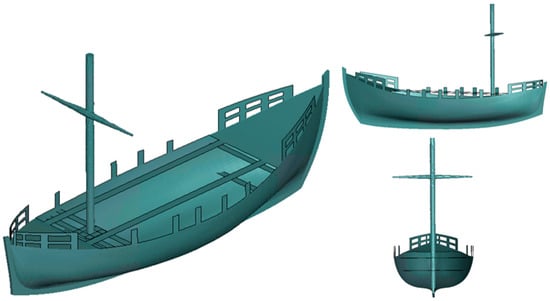
Figure 1.
CAD reconstruction of the Kyrenia ship, used as a benchmark case for structural modelling of small wooden merchant vessels.
2.2. Amphora Typology and Cargo Modelling
The presence of Corinthian B-type amphorae, Figure 2a, is inferred based on typological and chronological consistency with the Classical period. Similar amphorae from archaeological contexts in the central Mediterranean have shown chemical traces of wine and oil, supporting their interpretation as containers for bulk transport of such commodities [20]. These amphorae, typically measuring around 65 cm in height and 35 cm in width, are characterised by their robust shape and suitability for dense stacking in ship cargo holds. While direct evidence for Corinthian B amphorae on the original Kyrenia shipwreck site has not been confirmed, their dating corresponds to the period of Kyrenia’s activity, and their morphology aligns with cargo configurations typical of such merchant vessels. The inclusion of amphorae in the model is based on common archaeological methodology. When direct material evidence is incomplete or missing, researchers often rely on the typology of amphorae, such as their shape, dimensions, and origin, to reconstruct the likely cargo composition and arrangement. This approach is widely accepted in maritime archaeology and allows for a plausible reconstruction of cargo even when only fragmentary physical remains are available [21]. The amphora model was constructed based on the real exhibit, Figure 2a, using solid tetrahedral elements, as shown in Figure 2b, to capture the complex curved geometry of the Corinthian B-type vessel. However, to optimise computational performance and focus on ship–cargo interaction rather than amphora deformation, the amphorae were assigned rigid material properties. This assumption allows for faster simulations while maintaining realistic mass and volume, as the objective is not to evaluate amphora cracking or fracture behaviour, but to study how the cargo contributes to the shipwreck dynamics. This approach aligns with archaeological interpretations, where most of the amphorae recovered from the site were found intact or with minimal damage, suggesting the ship structure failed rather than the cargo itself.
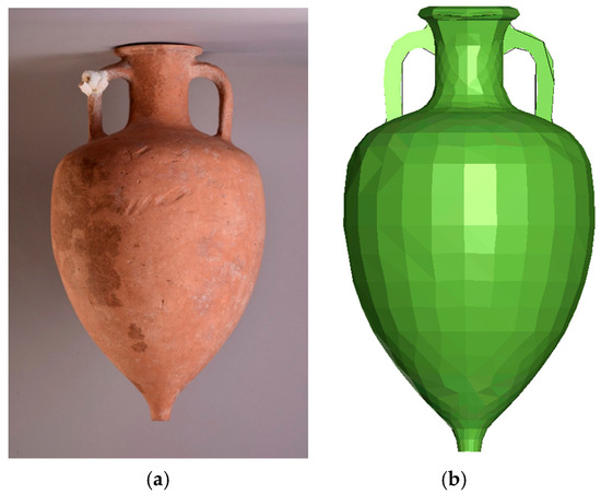
Figure 2.
Corinthian B amphora: (a) photograph, (b) CAD model.
2.3. Seabed Topography and Environmental Representation
The seabed topography used in the simulation was reconstructed from photogrammetric data collected during the 2017 archaeological survey of the Žirje site, Figure 3. Orthophotos and digital elevation models were processed to generate a surface of the local bathymetry, preserving key terrain features such as slopes, ridges, and depressions. The photogrammetric model also captured the distribution of artefacts across the site, which are highlighted in the figure to make them visible at this scale. The model has a positional accuracy of 3 mm per 1 m, equivalent to a maximum error of ~18 cm across the 60 m site. Depths were derived from a diving computer with ~10 cm variability, which for the site scale corresponds to a maximum angular error of ~0.1°. The mesh consists of triangular faces 3–4 cm wide, meaning that details smaller than ~4 cm cannot be resolved. This surface was scaled and aligned to match the real-world layout of the wreck, ensuring that hull–seabed interactions during sinking reflected actual site conditions. Including terrain data was essential for assessing the resting position, tilt, and orientation of the vessel relative to the gradient, as well as for evaluating cargo dispersal. While present seabed morphology may not fully replicate conditions from ca. 2400 years ago, geological surveys suggest the location has remained broadly stable, with limited sedimentation or erosion. Therefore, current bathymetric data provide the most reliable basis for approximating the ancient depositional context. The methodology corresponds to recent approaches in submerged cultural heritage documentation combining structure-from-motion photogrammetry with UAV mapping [22].
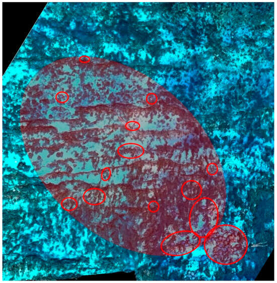
Figure 3.
Photogrammetric reconstruction of the Žirje shipwreck site, with highlighted details indicating the distribution of individual artefacts.
2.4. Finite Element Model and Simulation Setup
Before defining the numerical scheme, material properties and mesh strategy were first established to ensure accurate structural representation. The wooden hull was modelled using isotropic elastic properties, with timber parameters derived from ancient ship reconstructions and supplemented by recent characterisation of archaeological wood [23]. Amphorae were treated as rigid solids due to their brittle ceramic nature and the negligible role of elastic deformation in large-scale dynamics. This assumption is supported by archaeological evidence, as amphorae at the Žirje site (Figure 4b) were mostly recovered intact, indicating that transport and deposition did not cause significant ceramic deformation. Variability in contents was considered by applying averaged density values to account for wine, oil, or partially empty vessels. Mesh density and structural detailing were informed by similar simulation-based studies, such as the full-scale analysis of the Vasa warship [3] and updated best practices in historical vessel modelling [24]. This setup provided a robust structural foundation for subsequent dynamic simulations involving hydrostatic loading, cargo interaction, and shipwreck formation.
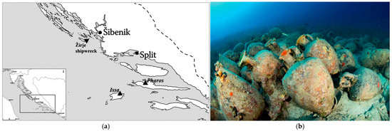
Figure 4.
Žirje shipwreck site: (a) Position of the shipwreck, (b) main concentration of amphorae [16].
The simulation employed LS-DYNA’s explicit solver for dynamic sinking events [25]. Three components were modelled: the wooden hull (shell elements), rigid amphora cargo (solid tetrahedral), and seabed (rigid CAD surface). Contacts used *CONTACT_AUTOMATIC_SINGLE_SURFACE for robust collision detection across all interfaces [26]. The explicit time-step Δt follows:
where Lmin is the smallest element edge length, E the elastic modulus, and ρ density. Mass scaling was avoided to preserve physical accuracy. Gravity was applied uniformly, while material damping was added (critical damping ratio ≈ 0.02) to filter spurious high-frequency responses. The total simulated duration (~3 s) covered sinking onset to seabed impact, capturing both hull dynamics and cargo movement.
3. The Shipwreck Site
In 2015, a non-looted site off the eastern coast of Žirje (Figure 4a) at a depth accessible to sport divers was unexpectedly discovered [16]. The initial expert survey concluded that the site consisted of a group of Corinthian B-type amphorae lying on a rocky slope of the seabed, with associated scattered material covering an area of approximately 20 by 50 m, at depths ranging from 20 to 38 m. The amphorae cargo spanned along a series of submerged rocky terraces. Besides transport containers, the site contained the cargo of small jugs with the so-called Heracles’ knot on the handles, and various kitchenware from the ship’s galley. Obviously, the finds presented the evidence of a shipwreck site, dated to the second half of the 4th century BC. A small merchantman ended at the rocky sea bottom, leaving amphorae and other cargo remains, but no obvious evidence of the hull. Two documentation campaigns performed in 2016 and 2017 produced a precise photogrammetric plan of the site.
The main concentration of the amphorae was recorded at a depth between 23 and 25 m, with a larger group located just below 25 m. Some amphorae were found scattered up to 20 m away from the main concentration, suggesting they were displaced either by the sinking process or subsequent underwater currents. Detailed sketches showing the positions of the main concentrations of amphorae on the seabed, both in horizontal and lateral views, are presented in Figure 5a and b.
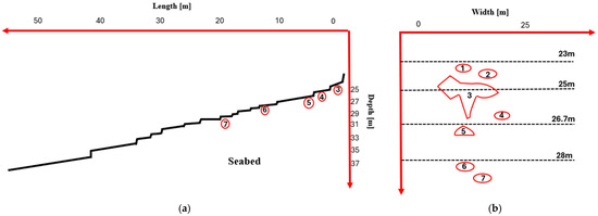
Figure 5.
Amphorae findings from the Žirje site: (a) lateral direction, (b) vertical direction.
4. Numerical Model
4.1. Model Assumptions
The numerical simulation was carried out using LS-DYNA 11.1. finite element software, under the following assumptions:
- Long-term post-depositional effects such as sedimentation, erosion, or biological disturbance were excluded from the simulation scope.
- Amphorae and ship were modelled as rigid, unreformable bodies, without accounting for breakage, fragmentation, or structural damage during impact or contact.
- Bottom impact was modelled as an instantaneous transition to the second phase, with no progressive or dynamic deformation of the seabed
- For the Žirje vessel, only the cargo mass (amphorae and ceramics) is known, which is approximately 6 tons, with the estimated mass of the ship at 6.5 tons, resulting in a combined weight of around 12.5 tons
4.2. Geometry, Materials, and Meshing
The numerical simulation was carried out using LS-DYNA 11.1. finite element software. The vessel was assumed to follow the general form of the Kyrenia ship, a well-documented 4th-century BCE Greek merchant vessel. Its geometry was uniformly scaled to match the estimated deadweight of the Žirje shipwreck. The cargo mass (amphorae and ceramics) is estimated at approximately 6 tons, and the ship mass at 6.5 tons, resulting in a combined displacement of 12.5 tons. The freeboard was scaled from 0.8 m to 0.65 m.
The ship structure was modelled using 20,734 Belytschko-Tsay shell elements, with rigid material properties and adjusted density to reflect 6 tons total mass (Figure 6a). Amphorae were modelled using 10-noded tetrahedral elements, ~1,400 per unit, giving a mass of 40 kg each (Figure 6b). Ceramic jugs (4 kg each) were similarly meshed and grouped into four baskets, twelve per basket (Figure 6c). All components were treated as rigid bodies to reduce computational cost.
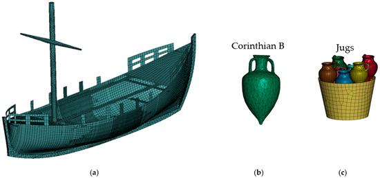
Figure 6.
Numerical model for the Žirje shipwreck scenario: (a) wooden hull, (b) Corinthian B amphorae cargo, (c) jug placed in baskets.
4.3. Contact, Boundary Conditions, and Simulation Parameters
All interactions were handled using AUTOMATIC_SINGLE_SURFACE contact, suitable for dynamic simulations involving multiple discrete parts. Gravity was applied using the LOAD_BODY_PART keyword, with a reduced vertical acceleration of 1.9 m/s2 to account for buoyancy effects:
where Fb is the buoyant force and W is the ship’s weight. The time step was fixed at 4 × 10⁻⁵ s to maintain numerical stability. No surrounding fluid was explicitly modelled. Instead, the seabed was included as a rigid surface. This simplification reduced computational time while preserving realistic structural and cargo behaviour. A 40 s simulation ran in ~4 h, capturing ~8 s of sinking and ~22 s of cargo dispersal. The duration was chosen to represent the physical phase from the loss of buoyancy until the vessel reached the seabed, during which motion was governed by gravity reduced by buoyant force. This efficiency enabled effective parametric studies of ship orientation and amphora movement. To replicate realistic cargo dispersal, gravitational accelerations were decoupled between the ship and the amphorae, assuming partial buoyancy or unsealed cargo, which allowed amphorae to exit the hull, unlike simulations with uniform gravity, where cargo remained trapped. The final configuration and structural layout of the simulation model are illustrated in Figure 7, showing the initial simulation position of the ship on the reconstructed seabed in Figure 7a, and the internal cargo arrangement, specifically the placement and distribution of amphorae prior to sinking, Figure 7b.
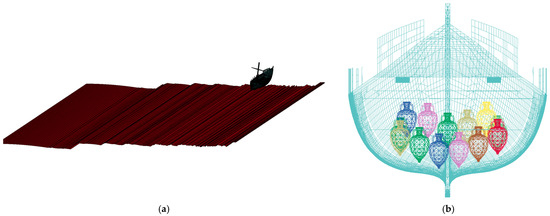
Figure 7.
Final numerical model of the Žirje shipwreck simulation: (a) isometric view, (b) section cu through the hull and cargo.”.
5. Results
The results are presented in two stages. The initial simulations aimed to explore the ship’s orientation before sinking and assess how different roll and yaw angles, along with varying gravitational accelerations, affect cargo dispersion. This analysis of initial orientation was necessary to determine the most plausible starting configuration of the vessel. A key goal was to evaluate whether the observed amphorae distribution could result from the sinking process alone, or if sea currents played a role under the condition that amphorae must first exit the ship to be carried away. These tests helped define realistic boundary conditions for the final full-scale simulation, which attempts to reconstruct the most plausible shipwreck scenario.
5.1. Analysis of Initial Orientation and Sinking Conditions
Initial simulations examined how different combinations of roll and yaw angles affect cargo dispersal. As previously discussed in Section 4, two configurations were considered: one in which the ship and cargo were subjected to the same gravitational acceleration (uniform sinking), and another in which they experienced different accelerations (non-uniform sinking). The latter case is based on the assumption that amphorae may not have been fully sealed or were partially filled with lightweight contents, leading to altered hydrodynamic behaviour. Definition of simulation scenarios is presented in Table 1.

Table 1.
Definition of parametric simulation scenarios.
If only the ship’s external dynamics are considered, Figure 8 shows that non-uniform sinking causes noticeably greater surge displacement, reaching about 0.7 m, compared to minimal movement in the uniform case. Heave displacement also differs, with non-uniform sinking showing a larger downward shift (up to −0.25 m), due to delayed submersion of cargo. Sway displacement stabilises near −16 m in both cases, indicating it is more influenced by initial roll or yaw than by sinking type. These diagrams were generated by post-processing nodal displacements of the ship’s centre of gravity using LS-PrePost 4.8. software. The duration of each simulation was 40 s of real time, capturing the full sequence from initial descent to final stabilisation upon seabed impact. This timeframe reflects the dynamic response of the system rather than the full real-world sinking duration.
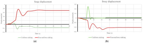
Figure 8.
Comparison of simulated vessel motions for the Žirje shipwreck under uniform and non-uniform sinking: (a) surge (b) sway.
Figure 9 illustrates the results of numerical simulations comparing two scenarios of initial ship roll: 0° and 40°, both subjected to the same effective gravitational acceleration (1.9 m/s2). The panels contrast amphorae dispersal between uniform and non-uniform configurations. In the uniform sinking case, amphorae remain confined within the hull throughout the descent, forming a compact cluster after seabed impact. This results in a maximum spread of only ~1.5 m—insufficient to match the archaeological findings. In non-uniform cases with increased roll, especially at 40°, amphorae exhibit significantly broader scatter, extending up to 2 m along the ship’s longitudinal axis. This irregular pattern aligns more closely with the archaeological observations, where amphorae were recorded up to 20 m away from the main wreck. These findings suggest that a neutral roll angle of 0° prior to sinking does not reproduce the physical evidence on the seabed. A more likely scenario involves pre-submersion inclination- possibly from cargo imbalance, structural failure, or external force. A roll of ~40° emerges as the most plausible initial state for replicating real-world amphora distribution.
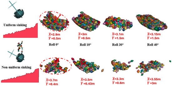
Figure 9.
Comparison of vessel motion for uniform and non-uniform sinking scenarios for roll angle variation.
Following the analysis of roll angles, yaw variation was introduced to reflect a realistic scenario in which the ship descends at an angle relative to the seabed due to external influences such as wind or currents. Two yaw angles, 10° and 20°, were tested without any initial roll, while additional simulations combined roll angles of 20° and 40° with the same yaw values.
As shown in Figure 10, yaw variation had a comparatively minor effect on amphora dispersion in both uniform and non-uniform sinking scenarios. In uniform sinking, even the maximum yaw angle (20°) resulted in negligible cargo scatter. In contrast, when combined with roll angles under non-uniform sinking, the yaw contributed to the widest dispersion patterns. However, in all uniform cases, the amphorae remained confined within the ship, further supporting the importance of asymmetrical sinking dynamics.
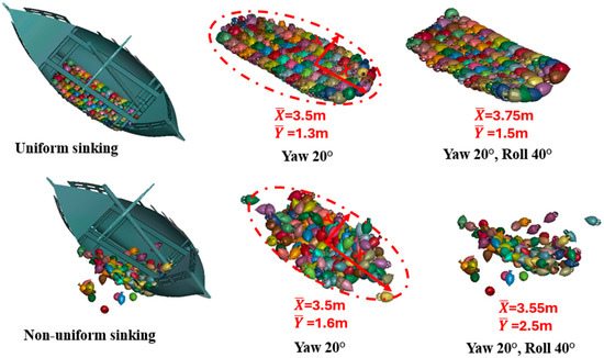
Figure 10.
Simulated amphora dispersal patterns for the Žirje shipwreck under yaw and combined yaw-roll conditions, comparing uniform and non-uniform sinking.
Distinct differences in amphorae dispersion are observed between uniform and non-uniform sinking scenarios, as shown in Figure 11. In the uniform case, the scatter remains narrow and primarily aligned with the ship’s longitudinal axis, with limited variation across different angles. In contrast, non-uniform sinking produces a broader and more irregular distribution, particularly at higher roll and yaw angles, resulting in wider lateral spread and greater overall displacement.
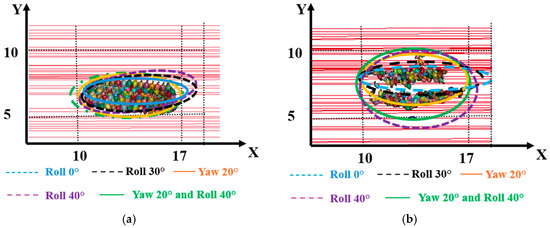
Figure 11.
Amphorae distribution patterns influenced by yaw and roll: (a) uniform sinking, (b) non-uniform sinking.
The conducted simulations clearly demonstrate that the vessel’s initial orientation, particularly roll angle, plays a dominant role in cargo displacement during sinking. While higher roll angles (30–40°) in non-uniform sinking scenarios resulted in broader lateral spread, yaw variation had comparatively minor influence. However, even in the most extreme tested conditions, the level of amphorae dispersion did not match the extent observed on site. This indicates that initial dynamics alone are insufficient to replicate the final distribution and suggests that additional environmental factors, most notably near-bottom sea currents, must be considered to accurately reproduce the conditions that shaped the actual cargo spread.
5.2. Final Shipwreck Scenario
The full shipwreck scenario was developed based on insights gained from the preceding parametric study. Several key assumptions were adopted:
- The only plausible condition is non-uniform sinking, in which the ship and its cargo are subjected to different gravitational accelerations. In contrast, uniform sinking would cause the amphorae to remain trapped within the hull and likely buried in sediment.
- Surge and sway components during the descent are considered negligible due to the high hydrodynamic resistance of the water. As a result, vertical heave motion is assumed to dominate the submersion process.
- Parametric results indicate that only an initial roll of 40°, or a combination of 40° roll and 20° yaw, produces sufficient amphorae dispersion during sinking.
- Even under optimal conditions, the dispersion pattern does not fully replicate the archaeological site. Therefore, additional environmental effects—specifically seabed currents—are considered necessary to explain the extended spread of amphorae.
The applied sea current forces are based on hydrodynamic data from the central Adriatic. While bottom currents in this region can temporarily exceed 0.3 m/s during strong wind events, their short duration and the shape of the amphorae suggest limited but important post-impact influence. In the simulation, these conditions are modelled as transient accelerations ranging from 0.25 to 0.4 m/s2 in the horizontal (X) direction and 0.05 to 0.1 m/s2 in the vertical (Z) direction, Figure 12b. These were applied for up to 20 s following seabed contact, representing the entrainment phase prior to stabilisation due to sediment and friction [27].
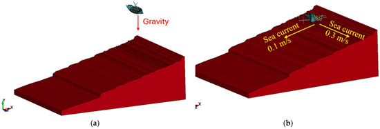
Figure 12.
Final simulation setup for the Žirje shipwreck scenario: (a) vessel dynamics during the sinking phase, (b) cargo dispersal under sea current influence.
The final dispersion of amphorae, recorded at the end of the 35 s full-scale simulation, is shown in Figure 13. The resulting spatial distribution exhibits a strong similarity to the amphorae scatter documented through underwater photogrammetry, both in terms of shape and overall spread. The simulated dispersion reaches a maximum diameter of approximately 20 m, which corresponds closely to the extent of the archaeological findings. This visual and dimensional agreement supports the validity of the combined sinking and bottom current scenario used in the simulation.
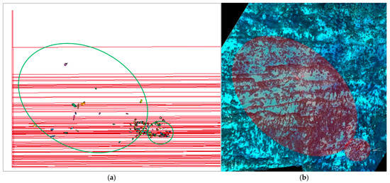
Figure 13.
Amphorae dispersion at the Žirje site: (a) numerical simulation results, (b) archaeological findings documented by photogrammetry.
6. Discussion
The results of this study highlight the potential of simplified numerical simulations in reconstructing plausible shipwreck scenarios. Compared to previous studies utilising fully coupled finite element or CFD structural models [2,3,4,5,6,7], the current approach strikes a balance between computational efficiency and interpretive value. While less detailed than high-fidelity models, it successfully captures the dominant physical processes governing cargo release and dispersion.
A key limitation of this study lies in the exclusion of fluid–structure interaction modelling and the simplified treatment of amphorae as rigid bodies with homogeneous mass. These assumptions overlook the complexity of amphora integrity, content variability, and hydrodynamic behaviour [13,14,17], which may affect dispersion trajectories in real conditions.
In addition, the archaeological interpretation of amphorae distribution remains subject to uncertainty. Post-depositional processes such as sediment movement, bioturbation, and anthropogenic disturbance can significantly alter the spatial configuration of the site over time. Nevertheless, in the case of the Žirje shipwreck, it is also reasonable to assume that many amphorae remained close to their original depositional positions, as they were rapidly embedded in sediment and stabilised by friction, which limited their subsequent displacement. Thus, while secondary modifications cannot be excluded, the present-day configuration likely preserves the main characteristics of the original cargo dispersal. Furthermore, the original cargo loading pattern and the exact contents of individual amphorae are unknown, introducing further variability.
Despite these limitations, the combination of simulation data and archaeological observation provides a coherent explanation for the spatial characteristics of the Žirje shipwreck. Future studies may benefit from incorporating fluid modelling, material heterogeneity, and site-specific sediment dynamics to further improve reconstruction accuracy.
7. Conclusions
This study investigated a plausible sinking scenario of the ancient shipwreck near the island of Žirje by combining numerical simulations with archaeological evidence. The following key insights were obtained:
- Uniform sinking, where both the ship and cargo are subjected to the same gravitational acceleration, did not lead to realistic cargo dispersal. Amphorae remained confined within the hull and would likely have been buried by sedimentation, which contradicts the widespread distribution observed during site investigations.
- Non-uniform sinking, achieved by applying different gravitational accelerations to the ship and the cargo, enabled amphorae to separate from the hull. This configuration better explains how the cargo could have escaped and scattered across the seabed.
- Initial roll angles of 30 to 40 degrees proved essential for producing wider cargo dispersion. Lower roll values and yaw alone did not result in meaningful scatter.
- Final amphorae distribution comparable to that documented at the Žirje site could not be achieved without introducing sea current effects. When transient bottom currents were added, dispersal expanded up to 20 m in diameter, aligning with photogrammetry data.
- Surge and heave motion in the non-uniform case was more pronounced, particularly during cargo release, indicating that cargo behaviour significantly influences the vessel’s external dynamics during sinking.
This model therefore provides a realistic and well-supported scenario for the formation of the Žirje shipwreck site. The results demonstrate how simplified simulations, when combined with archaeological evidence, can serve as a valuable tool for future reconstructions of ancient shipwrecks and cargo dispersal patterns.
Author Contributions
Conceptualization, Š.S., S.R. and I.R.R.; methodology, Š.S., S.R. and I.R.R.; software, Š.S. and S.R.; validation, Š.S.; formal analysis, Š.S.; investigation, Š.S., S.R. and I.R.R.; resources, I.R.R.; data curation, I.R.R.; writing—original draft preparation, Š.S.; writing—review and editing, S.R. and I.R.R.; visualization, Š.S.; supervision, S.R. and I.R.R.; project administration, I.R.R.; funding acquisition, S.R. and I.R.R. All authors have read and agreed to the published version of the manuscript.
Funding
This work was supported by the Croatian Science Foundation within the project NEREAS–Numerical Modelling in the Archaeology of Seafaring, IP-2020-02-3420.
Institutional Review Board Statement
Not applicable.
Informed Consent Statement
Not applicable.
Data Availability Statement
The original contributions presented in the study are included in the article, further inquiries can be directed to the corresponding authors.
Conflicts of Interest
The authors declare that they have no known competing financial interests or personal relationships that could have appeared to influence the work reported in this paper.
References
- Rudan, S.; Sviličić, Š.; Bolf, D.; Radić Rossi, I. Numerical reconstruction in maritime archaeology. J. Mar. Sci. Eng. 2023, 11, 1184. [Google Scholar] [CrossRef]
- Rudan, S.; Radić Rossi, I. Numerical simulation of a sinking ship scenario based on archaeological records. Archaeol. Adriat. 2020, 14, 139–157. [Google Scholar] [CrossRef]
- Afshar, R.; Alavyoon, N.; Ahlgren, A.; Gamstedt, E.K. Full scale finite element modelling and analysis of the 17th-century warship vasa: A methodological approach and preliminary results. Eng. Struct. 2021, 231, 111765. [Google Scholar] [CrossRef]
- Palmer, C. Windward sailing capabilities of ancient vessels. Int. J. Naut. Archaeol. 2009, 38, 314–330. [Google Scholar] [CrossRef]
- Lasher, W.C.; Flaherty, L.S. CFD analysis of the survivability of a square-rigged sailing vessel. Eng. Appl. Comput. Fluid Mech. 2009, 3, 71–83. [Google Scholar] [CrossRef]
- Ciortan, C.; Fonseca, N. Numerical simulations of the sails of a XVIth century Portuguese Nau. In Proceedings of the International Conference on Computational Methods in Marine Engineering (MARINE 2011), Lisbon, Portugal, 28–30 September 2011; pp. 278–289. [Google Scholar]
- Stettler, J.W.; Thomas, B.S. Flooding and structural forensic analysis of the sinking of the RMS titanic. Ships Offshore Struct. 2013, 8, 346–366. [Google Scholar] [CrossRef]
- Kery, S. Marine Forensics: The Art and Science of Simulating Ships in Storm Conditions. In Proceedings of the Interservice/Industry Training, Simulation, and Education Conference (I/ITSEC) 2017, Orlando, FL, USA, 27 November–1 December 2017. [Google Scholar]
- Subbaiah, B.V.; Thampi, S.G.; Rambabu, N.; Mustafa, V.; Akbar, M.A. Characterization and CFD analysis of traditional vessels of Kerala. Int. J. Innov. Technol. Explor. Eng. 2020, 9, 132–149. [Google Scholar] [CrossRef]
- Fawsitt, S.; Hobberstad, L.C. Computational fluid dynamics: Floating a digital barcode 02. Archaeonautica 2021, 21, 325–330. [Google Scholar] [CrossRef]
- Miše, M. Provenance studies of transport amphorae from the Žirje shipwreck. In Where This Ship is Saling To? Shipwreck from the 4th Century BC on the Seabed of the Island of Žirje, Exhibition Catalogue; Miliša, M., Miše, M., Radić Rossi, I., Rogošić, F., Eds.; Art Academy of the University of Split: Split, Croatia, 2022; pp. 27–38. [Google Scholar]
- Barone, G.; Mazzoleni, P.; La Russa, M.F.; Pezzino, A. Archaeometric analyses on ‘Corinthian B’ transport amphorae found at Gela (Sicily, Italy). Archaeometry 2004, 46, 553–568. [Google Scholar] [CrossRef]
- Barilaro, D.; Barone, G.; Crupi, V.; Majolino, D.; Mazzoleni, P.; Triscari, M.; Venuti, V. Characterization of ancient amphorae by spectroscopic techniques. Vib. Spectrosc. 2006, 42, 381–386. [Google Scholar] [CrossRef]
- Le Sourne, H.; Couty, N.; Besnier, F.; Kammerer, C.; Legavre, H. LS-DYNA applications in shipbuilding. In Proceedings of the 4th European LS-DYNA Users Conference, Ulm, Germany, 22–23 May 2003; pp. A-II-01–A-II-16. [Google Scholar]
- Kim, S.J.; Sohn, J.M.; Kujala, P.; Hirdaris, S. A simplified fluid–structure interaction model for the assessment of ship hard grounding. J. Mar. Sci. Eng. 2022, 10, 211. [Google Scholar] [CrossRef]
- Radić Rossi, I.; Grisonic, M.; Batur, K. The newly discovered 4th century BC shipwreck at the island of Žirje. In Where is This Ship Sailing To? Shipwreck from the 4th Century BC in the Seabed of the Island of Žirje; Miliša, M., Miše, M., Eds.; Art Academy of the University of Split: Split, Croatia, 2022; pp. 11–26. [Google Scholar]
- Rudan, S.; Radić Rossi, I.; Jerat, G.; Zamarin, A.; Sviličić, Š.; Lucchini, A. The effect of changing the beam of an ancient ship’s hull on its capacity, stability, and performance. Heritage 2024, 7, 6712–6728. [Google Scholar] [CrossRef]
- Steffy, J.R. Wooden Ship Building and the Interpretation of Shipwrecks; Texas A&M University Press: College Station, TX, USA, 1994. [Google Scholar]
- Robert McNeel & Associates. Rhinoceros 3D, Version 7.0; Robert McNeel & Associates: Seattle, WA, USA, 2020. Available online: https://www.rhino3d.com (accessed on 16 May 2025).
- Semeraro, G.; Notarstefano, F.; Caldariola, R.; Quarta, G.; Calcagnile, L. Investigations on provenance and content of archaic transport amphorae from Castello di Alceste (S. Vito dei Normanni-Br) by chemical analyses through XRF/FP and GC-MS. In Proceedings of the IMEKO TC4 International Conference on Metrology for Archaeology and Cultural Heritage, Lecce, Italy, 23–25 October 2017; pp. 388–392. [Google Scholar]
- Miše, M.; Quinn, P.S. Origins and distribution of Hellenistic and late republican transport amphorae in the dalmatian region and its implications for Adriatic trade and economy. Archaeol. Anthropol. Sci. 2022, 14, 225. [Google Scholar] [CrossRef]
- Mazza, D.; Parente, L.; Cifaldi, D.; Meo, A.; Senatore, M.R.; Guadagno, F.; Revellino, P. Quick bathymetry mapping of a Roman archaeological site using RTK UAS-based photogrammetry. Front. Earth Sci. 2023, 11. [Google Scholar] [CrossRef]
- Wu, M.; Han, X.; Qin, Z.; Zhang, Z.; Xi, G.; Han, L. A quasi-nondestructive evaluation method for physical-mechanical properties of fragile archaeological wood with TMA: A case study of an 800-year-old shipwreck. Forests 2022, 13, 38. [Google Scholar] [CrossRef]
- Helfman, N.; Nishri, B.; Cvikel, D. Finite element analysis of shell-first and longitudinally reinforced frame-based wooden ships. J. Mari. Arch. 2019, 14, 291–309. [Google Scholar] [CrossRef]
- ANSYS, Inc. Technical Guide for Explicit Analyses using ANSYS LS-DYNA; ANSYS: Canonsburg, PA, USA, 2024. [Google Scholar]
- Livermore Software Technology Corp. Contact Modeling in LS-DYNA User’s Guide; LSTC: Livermore, CA, USA, 2023. [Google Scholar]
- Bolaños, R.; Tornfeldt Sørensen, J.V.; Benetazzo, A.; Carniel, S.; Sclavo, M. Modelling ocean currents in the northern Adriatic sea. Cont. Shelf Res. 2014, 87, 54–72. [Google Scholar] [CrossRef]
Disclaimer/Publisher’s Note: The statements, opinions and data contained in all publications are solely those of the individual author(s) and contributor(s) and not of MDPI and/or the editor(s). MDPI and/or the editor(s) disclaim responsibility for any injury to people or property resulting from any ideas, methods, instructions or products referred to in the content. |
© 2025 by the authors. Licensee MDPI, Basel, Switzerland. This article is an open access article distributed under the terms and conditions of the Creative Commons Attribution (CC BY) license (https://creativecommons.org/licenses/by/4.0/).