Abstract
In order to revitalize and preserve the Paimogo Fort, a Portuguese coastline military fortification built in 1674 and classified as of public interest since 1957, several lime-based repair rendering mortars were developed, considering the compatibility requirements with the original ones. In this investigation, the different lime-based mortar compositions proposed are briefly described and their main physical and mechanical characteristics are analyzed at successive ages (28, 90 and 180 days). Furthermore, some applications of the same mortars’ compositions on different porous substrates were carried out and their performances in laboratory and in situ conditions were compared. Finally, the possible degradation mechanisms and the impact of the composition, interaction with the substrate and climatic and environmental conditions on the durability of the mortars are discussed. The main outcomes show that mortars with some content of quicklime result in a balanced solution for the restoration work of the fort; they show an increase of more than 50% of strength compared to slaked air lime mortars, namely when applied on a medium-absorbent substrate. When applied on very absorbent substrates, although improving the compressive strength and porosity, all lime-based mortar compositions suffer a decrease in their modulus of elasticity and adhesion to the substrate. Air lime mortar compositions applied on a very absorbent and porous substrate generally show an increase in their mechanical strength when subjected to the severe marine environment of the fort.
1. Introduction
The renders of historical buildings in coastal areas have been subjected, over the years, to an aggressive environment of salty mist, high relative humidity, hot sun, dry wind and, sometimes, even to waves’ strength. Notwithstanding the severity of the sea environment, ancient lime mortars used for joints and renders of this kind of constructions prove to be very resistant and durable and show essentially superficial degradation, such as biological colonization, dirty stains and heterogeneous surfaces [1]. Although most of these defects could be easily repaired, some of these buildings have, over the last few decades, suffered intrusive repair interventions, often with incompatible solutions, producing severe damage, such as detachments, erosion, loss of cohesion and presence of salt efflorescences and cryptoflorescences.
An accurate choice of the repair mortar is fundamental for successful restoration works: it is expected that the new repair mortar provides resistance to the existing environmental conditions and protects the original substrate, as well as being as durable as possible [2,3]. The new mortars need to be mechanically resistant but should not transmit high stresses to the substrate and restrain its movements; besides, they should not have high contents of soluble salts in order to avoid the increase in salt contamination into the walls, and they need to have the ability to protect the wall against rain, avoiding quick penetration at a high quantity; they are also required to facilitate the evaporation of water as much as possible, in liquid and vapor form, both infiltrated and originated by capillary rising [2,3,4,5]. However, the mortar performance does not depend only on the raw materials and on application but is also related to the characteristics of the substrate [6] and to the environmental exposition [7,8,9], which can create some technical challenges in the mortar formulation for the conservation of these buildings.
In a similar case study, in a fort at the Lisbon costal area, a mixed binder lime–white cement mortar was applied in two thin coats of 1:1:6, as a base coat, and 1:2:9, as the finishing coat (cement/lime/siliceous aggregate, by volume), with acceptable results for the last 30 years [10]; however, it is well known that the use of high percentages of cement, besides presenting lower water vapor permeability than lime-based materials, favors salt damage and induces an excessive mechanical strength and elastic modulus that could compromise the walls’ durability.
The use of different additives has been studied in the literature [11,12,13]; however, there is not yet enough consensus about the advantages of specific advanced formulations, as in the case study of a fortification near Lisbon, applied for 20 years, where an industrial pozzolanic addition, namely metakaolin, was added to the lime in the new repair mortars using 1:0.5:2.5 (lime/metakaolin/siliceous aggregate, by volume). However, it presents high levels of degradation today [14].
The case study of Paimogo Fort, a military structure built in 1674 in the municipality of Lourinhã, approximately 76 km north of Lisbon, reflects some of these difficulties. Abandoned during the first half of the 19th century, it suffered severe damage due to the lack of maintenance in the aggressive maritime environment to which it is exposed. The latest renovation work, carried out on the building in 2006, which involved replacement of the original rendering and plastering mortars with new ones, based on hydraulic lime mortars, demonstrated the difficulty of this task since, only fifteen years later, the repair mortars showed significant signs of deterioration (e.g., loss of cohesion, cracking, erosion) [15].
In this case study, due to the diversity of raw materials used in its construction and the aggressive environmental conditions to which the fort is subjected, it is required that the new mortars present good performance and durability to those conditions, as well as being chemically, mineralogically and physically–mechanically compatible with the original materials. Nevertheless, previously developed studies demonstrate that the performance obtained in the laboratory is not always representative of in situ behavior, particularly in the long term [13]. In this sense, within the scope of the “Coastal Memory Fort” Project, financed by the EEA Grants—Culture Program 2014-2021, promoted by Lourinhã Municipality, the National Laboratory for Civil Engineering (LNEC) was responsible for characterizing the existing renders [15] and formulating repair mortars to be applied to this monument.
Several lime-based mortars with compositions close to the original ones were considered as possible repair mortars. Given that the hygro-mechanical properties of mortars change with the type of substrate (due to different physical properties), in the present investigation, they were applied on substrates with different porosity, and the resulting physical–mechanical performances were characterized. Moreover, some of those compositions were exposed in the fort area to better understand the impact of real exposure conditions on the performance of these mortars. Their behavior and the possible degradation mechanisms were investigated, considering the substrate characteristics. Finally, all the results were considered and discussed to choose the most compatible and durable repair mortar compositions, to be chosen for the rehabilitation of the fort.
2. Case Study and Research Aims
Built on the cliffs of Paimogo beach (Lourinhã) in the XVII century, the Nossa Senhora dos Anjos de Paimogo Fort, better known as Paimogo Fort, is a coastal military structure, classified as of public interest since 1957, which was part of the defensive system of the Lisbon region [16].
The original fort structure (interior and exterior), with one single floor, is composed of masonry walls, made of irregular stone (limestone and sandstone, from local quarries [17]) bonded with air lime mortar. This structure, on its internal and external surfaces, was originally covered also by air lime mortars, applied in several layers. In the interior of the fort, the ceiling vaults were made with porous clay bricks, also originally covered with air lime plasters.
According to the LNEC Report [15], the original mortars analyzed in the laboratory were composed of calcitic air lime and siliceous and limestone sand of coastal origin with crustacean shells (Figure 1).
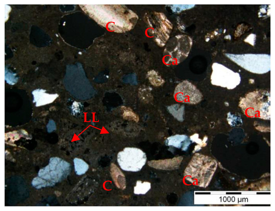
Figure 1.
Photomicrograph under polarized light with x nicols of the original sample, collected at external surfaces of the fort structure [15]. (Notation: LL—lime lumps; C—carbonated shells; Ca—calcareous aggregate).
The investigations carried out by Veiga et al. [15] also showed that the original mortars, rich in lime, had good mechanical properties and deformability and a moderate capacity for water absorption by capillary action (Table 1). However, most of the original air lime renders and plasters were removed in an intervention in 2006 and replaced by new ones, based on hydraulic lime, that showed degradation, especially erosion and loss of cohesion (Figure 2).

Table 1.
Original mortar compositions and main characteristics [15].
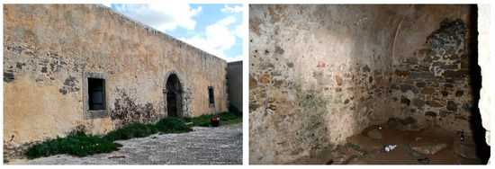
Figure 2.
Paimogo Fort (exterior and interior) in 2021.
Thus, after an extensive characterization of the original mortars, new mortar formulations, with compositions close to the original ones, were proposed and tested by LNEC in order to select the new repair mortar composition [18]. The investigation described in this paper included both laboratory and in situ tests using different types of brick substrates, whose main results aimed to assess the suitability of several repair mortar formulations by characterizing their physical, mechanical and hydric properties when applied on substrates with different absorption characteristics.
Concerning the new repair mortars, the aim is to obtain materials with physical–mechanical characteristics close to the original mortars. However, it is expected for the laboratory results to show slightly lower mechanical strengths and slightly higher water absorption coefficients than the original mortar characteristics (Table 1) because the carbonation process is still in progress, and the applications on brick substrates are made in a single layer. Moreover, relatively low adherence values to the substrate [19] are also expected since the formulations are based on lime and their strengths are expectable to enhance with the curing time.
3. Materials and Methods
3.1. Mortar Materials and Mixes
Concerning the knowledge of the old materials [15] and the previously determined chemical, physical and mechanical compatibility with the background and the pre-existent materials, a set of mortar compositions with different characteristics was selected (Table 2). The requirements were a similar composition to the original ones and simultaneously physical–mechanical characteristics as close as possible to the old mortars.
Table 2.
Mortar compositions (by volume).
An air lime mortar (A), composed of calcitic air lime (CL90-S, according to EN 459-1 [20]) and natural siliceous sand (d = 0/2 mm) from the Tagus River, was used as the base mortar due to being the simplest mortar with a similar composition to the original ones, and thus with a high compatibility with the ancient masonry [21] (Table 2 and Figure 3).
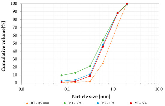
Figure 3.
Grain size distributions of the sand from the several sands used in new formulations.
Further, to respect the authenticity principles, trying to get closer to the composition of the old mortars and also to their mechanical properties, which were higher than the chosen base mortar, quicklime (CL90-Q—R5, P2, according to the EN 459-1 [20]) was added to the hydrated air lime mortar (A) composition [22,23,24] by the substitution of 30% of slaked air lime by volume just before use.
Moreover, since the repair mortars will be applied in a severe marine environment, where additional strength is needed and some hydraulicity may be favorable, slightly hydraulic mortars were used, obtained through the use of mixes of air lime with 25% of white Portland cement (CEM II/B-L 32.5R, according to EN 197-1 [25]). This relatively low content of cement was chosen in order to keep the porosity and moisture transport properties similar to the old mortar [9]. Additionally, a natural hydraulic lime (NHL5, according to the EN 459-1 [20]) was also assessed.
Additionally, to approach the original mortar compositions and improve the mortars’ performance [26], a fine-tuning of the aggregates was performed, substituting part of the siliceous sand with fine limestone sand (d = 0/1 mm) in 30% (M1), 10% (M2) and 5% (M3) by volume.
All the air lime mortars were formulated with a binder/aggregate ratio of 1:2 in volume in order to approach the high lime content of the original mortars, while, for the hydraulic ones, a proportion of 1:3 was used due to the expected higher strength of the binder. All the mortar compositions are described in Table 2 and Figure 3.
The mortars were prepared according to the protocol defined in EN 1015-2 [27], except for mixes incorporating quicklime, for which the method had to be adapted due to their very short hardening time, significantly reducing their workability. The main objective for adding quicklime to the slaked lime, just before application, was to provide the volume stability of the lime mortars, thus reducing cracking, enhancing the mechanical strength and, consequently, durability of the lime mortars [23,24]; however, due to the high temperature developed during hydration and quick setting, it was necessary to adapt the mixing procedure to be able to apply these mortars. The stages involved in the adapted mixing process were as follows: firstly, the dry solid constituents of the mortar (slaked air lime + quicklime + sand) were mixed. Secondly, 90% of the predetermined amount of water (Table 2) was added to the dry solid mix and into the mortar mixer, and all the constituents were mixed for a period of 5 min, with the mixer running at low speed, followed by a rest period of 10 min1. Thirdly, the mortars were mixed for a further 5 min at low speed, adding the remainder of the mix water (10%) to confer good plasticity and workability.
3.2. Substrates Characterization
To evaluate the performance of the mortars when applied on porous substrates, all mortar compositions (Table 2) were prepared and applied, in a single layer with a thickness of 20 ± 2 mm, on common ceramic bricks (30 cm × 20 cm × 11 cm), with the main characteristics defined in Table 3. This substrate was selected since its water absorption is comparable to the external walls of the fort.
Table 3.
Main physical characteristics of the substrate used.
Even if the same initial composition is used, the final pore structure of the hardened mortar differs when applied on substrates with different physical properties, and, consequently, the mortar’s hygro-mechanical properties also vary [6]. Thus, in this investigation, the mortars were additionally applied on a more porous and absorbing substrate—traditional solid calcined bricks (23 cm × 11 cm × 7 cm), which tend to simulate the very absorbent bricks of the internal vaults of the fort (Table 3).
After the application, the mortar surface of each specimen was sprinkled with water every 24 h for three days. Then, the mortars were cured at 20 ± 2 °C and 65 ± 5% RH until the testing dates (28, 90 and 180 days).
3.3. Environmental Exposition
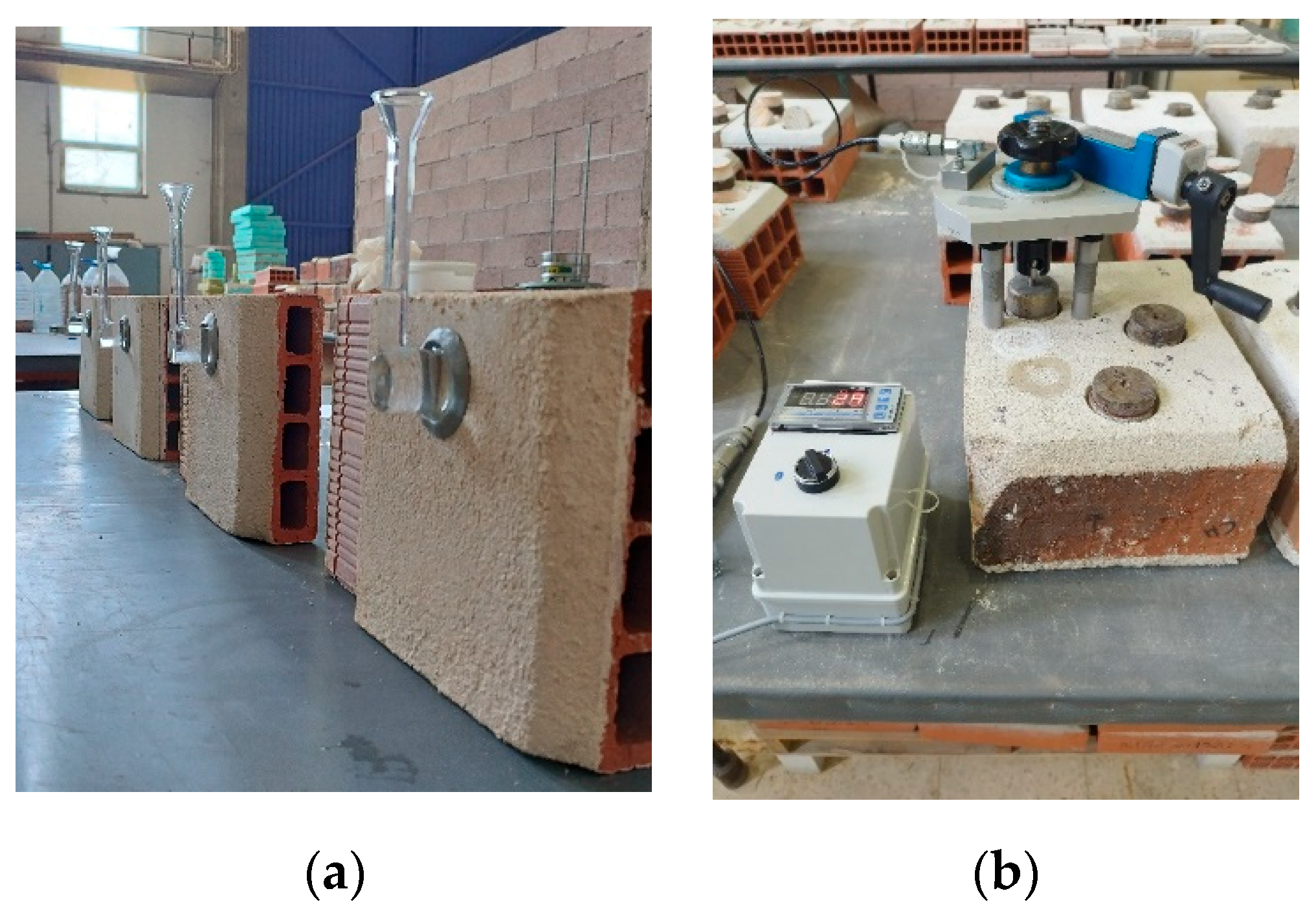
To assess the effect of the climatic and environmental conditions on mortars behavior and durability, the reference mortar compositions (A, A+Q30%, C:A and NHL mortars) were also applied on mini-wallettes composed of three traditional porous bricks with large joints of lime-based mortars with a long period of carbonation (Figure 4a) and subjected to the same laboratory cure conditions for 15 days, followed by exposure to the fort’s maritime environment (Figure 4b) for approximately ten months (September 2021 to July 2022). The period of exposure comprised the most severe conditions, considering both winter and summer climatic parameters. The mortar surface was exposed to the west, since this is the direction of the prevailing winds and faces forward to the ocean.
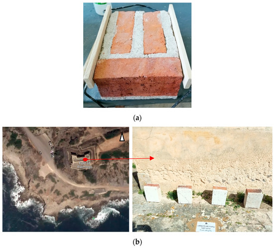
Figure 4.
(a) Applications on mini-wallettes and (b) exposition to the fort environment (on the terrace of the fort, exposed to the west).
During this exposition, interval parameters like temperature, relative humidity and wind speed were registered [31]: the average relative humidity was 75% and was characterized by quick showers during most of the period of exposition. The average daily air temperature ranged between 12 and 20 °C, with a maximum diurnal temperature variation register of 12 °C. In general, the wind registered in the fort was strong (average of 20 km/h), with some wind gusts of more than 50 km/h.
3.4. Methodology
In this research, the search for a suitable formulation for the restoration mortar of the Paimogo Fort was carried out by assessing the behavior and durability of mortars applied to bricks and cured both in the laboratory and in the fort environment.
The research comprised four main tasks:
- Task 1—application of reference mortar compositions (Table 4) on a medium-porous substrate (common ceramic bricks) to characterize the main physical and mechanical properties under laboratory conditions.
Table 4. Types of substrate and exposition conditions carried out in each mortar’s compositions.
- Task 2—application of reference mortar compositions (Table 4) on a very porous substrate (traditional solid bricks) in order to detect any variations in mechanical and physical properties, depending on the type of substrate, under laboratory conditions, since a heterogeneity of materials was found in the fort masonry.
- Task 3—application of the reference mortar compositions on mini-wallettes of very porous traditional solid bricks, and then placing them outdoors in the fort environment for a period of approximately ten months to assess the durability in the fort’s environmental conditions.
- Task 4—modification of mortar compositions evaluated as having better performance at the end of the initial tasks (Task 1, 2 and 3) to approach the original mortar compositions. Thus, part of the siliceous sand was substituted by limestone aggregate at 30% (M1), 10% (M2) and 5% (M3) by volume (Table 2 and Figure 3). The new mortar formulations were applied on medium-porosity common ceramic bricks and the main physical and mechanical properties under laboratory conditions were evaluated.
Table 4 summarizes the substrate types and the exposition conditions used for each formulation of repair mortars.
The properties of the mortars were assessed in the laboratory (Tasks 1, 2 and 4) using non-destructive tests (measurement of ultrasound propagation and surface hardness) at 28, 90 and 180 days to monitor changes in their properties during the carbonation process. At 180 days, destructive tests (flexural and compressive strengths, porosity and adhesion to the substrate) as well as a test of water permeability at low pressure were also performed.
To assess the performance and durability under the fort’s environmental conditions (Task 3), the non-destructive tests mentioned above (measurement of ultrasound propagation and surface hardness) were also carried out regularly throughout the exposition period (September 2021 to July 2022). At the end of the exposure period, destructive tests (flexural and compressive strengths, porosity and adhesion to the substrate), as well as tests of water permeability at low pressure, were also carried out under laboratory conditions.
Furthermore, visual observation of the specimens and presence of anomalies (cracks, discontinuities, loss of cohesion, etc.) were photographically recorded during the entire period of analysis.
3.5. Test Methods
The test methods used are described below:
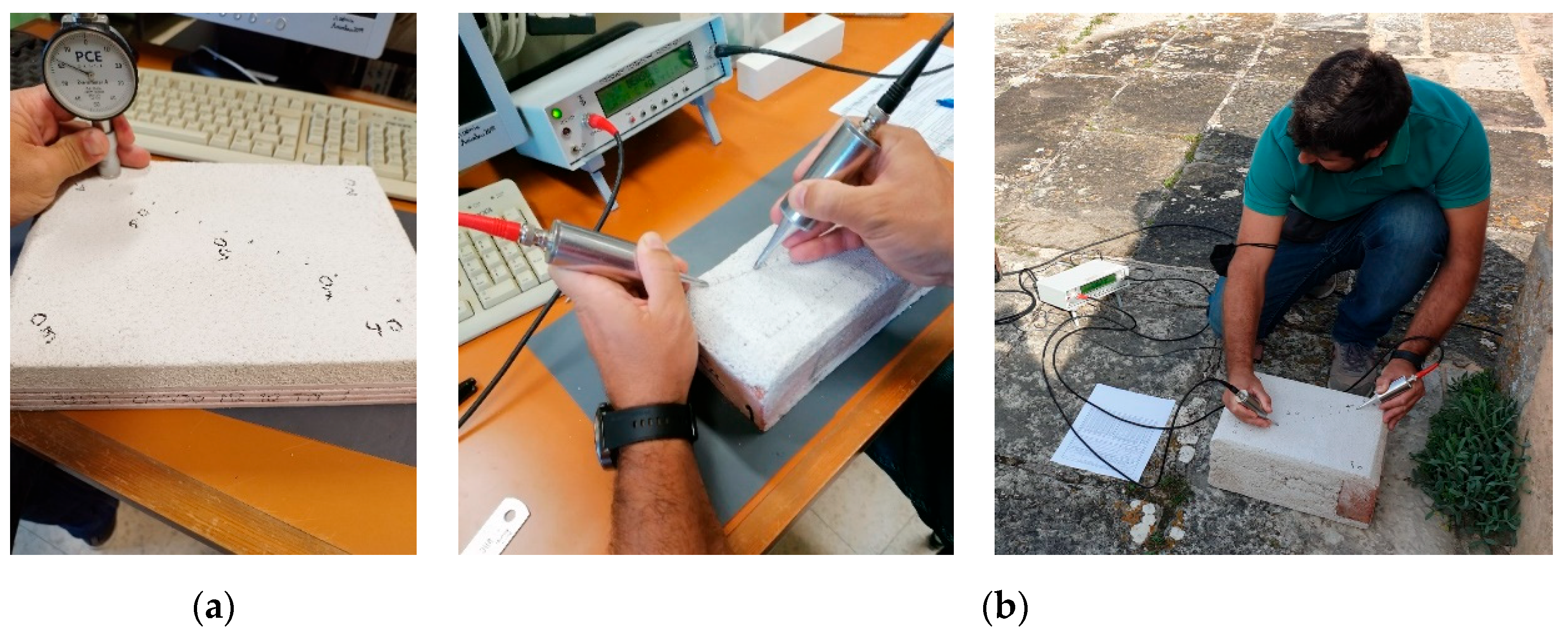
- Shore hardness (with a Shore A durometer) is a non-destructive method used to evaluate the surface hardness and, indirectly, the surface cohesion. In this test, the Shore A durometer, with a point, is pressed against the mortar surface by the action of a spring with a standardized force, giving a measure of the surface hardness on a scale ranging from 0 to 100 (Figure 5a). The greater the measure, the greater the surface hardness and cohesion. The test is based on the ISO 7619 [32] and ASTM D2240 [33] standards. Five measurements were performed at different points of each specimen.
 Figure 5. Non-destructive tests performed at the laboratory and in situ on the mortars applied on the bricks samples: (a) surface hardness measurement; (b) ultrasound test.
 - Ultrasonic pulse velocity test is also a non-destructive method for measuring dynamic properties of the mortars, such as the elastic modulus. Ultrasonic velocity measurements are also useful for detecting levels of deterioration that could cause a decrease in the mechanical properties, even while no visible decay effects are found [34]. This technique was carried out in accordance with standard NP EN 12504-4 [35], which consists of measuring the speed of propagation of longitudinal ultrasonic waves (P-waves), through the mortar specimens, between a transmitter and a receiver placed at a known distance from each other. In this research, a Steinkamp Ultrasonic tester BP-7 device was used to determine the propagation speed of ultrasonic waves with exponential transducers of 45 kHz. The indirect transmission method was used (transducers positioned on the same surface) with a distance of 20 mm between them and successively increasing the distance by displacing one of the transducers (Figure 5b).The RILEM Test Method III.2 [36] provides a simple means for measuring the dynamic modulus of elasticity (E, MPa) of the mortar, using Equation (1):where (kg/m3) is the bulk density of the mortar previously determined in the laboratory, using the hydrostatic weighing method [30], (m/s) is the velocity of the ultrasonic wave, determined as the slope of the linear regression of the distance as a function of time obtained experimentally, and φ (-) is the dynamic Poisson coefficient material, which is assumed to be 0.2 for all mortars tested, according to the literature [37].
- Water permeability at low pressure was tested in accordance with EN 16302 [28], using Karsten tubes to evaluate the waterproof capacity of the mortar. The test technique consists of registering the volume of water absorbed by a surface during chosen time-spans, using pipe-shaped tubes that are fixed to the surface in order to study (Figure 6a). In this work, for each tube, the water level was registered at the following time intervals: each minute until 5 min and then 10, 15, 20 25 and 30 min.
 Figure 6. Tests performed in laboratory on the mortar specimens at 180 days and at the end of the exposure period: (a) low-pressure water permeability measurement; (b) pull-off test.
 - Pull-off test was carried out to assess the adhesion between the mortar and the substrate. The test is based on the EN 1015-12 [38] standard and is performed by fixing, with an epoxy adhesive, a metallic disc to the mortar surface in order to apply a tensile force normal to the surface to be tested. The force is then gradually applied to the disc and the failure occurs along the weakest plan within the system (Figure 6b). The maximum stress is then calculated by dividing the tensile force value obtained by the area of the disc. Three measurements for each mortar composition were made in this investigation using a testing machine for direct pull tensile force: model Controls C 215/D, with a capacity of 0 to 5000 N and resolution of 50 N.
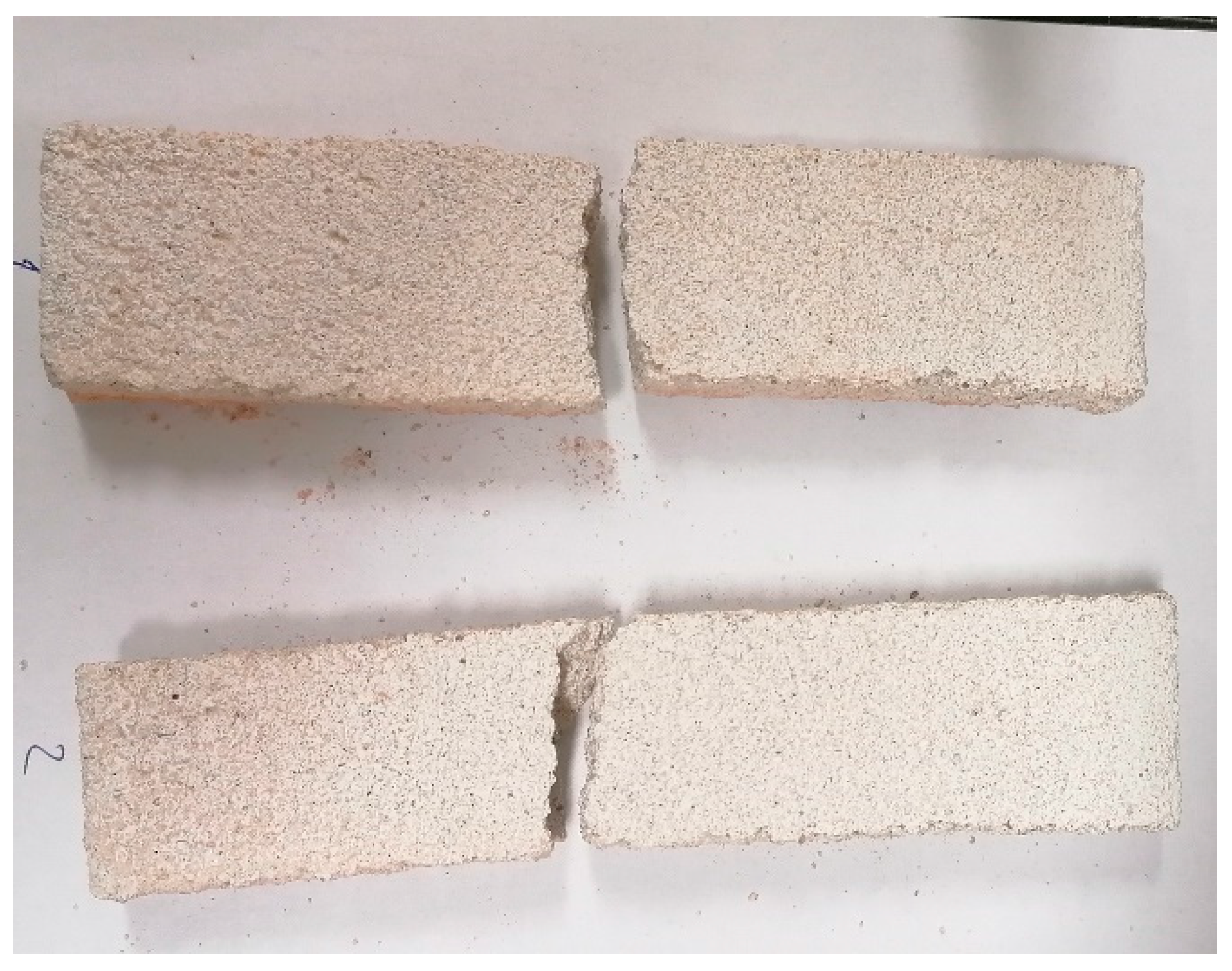
To characterize the mortars applied on the bricks (common ceramic, traditional very porous bricks and very porous mini-wallettes) in some destructive tests (flexural and compressive strengths as well as open porosity), it was necessary to adapt the specimen dimensions to the normalized tests dimensions. Thus, slices of the mortars, of 50 ± 2 mm, were cut and then detached from the substrate (Figure 7).
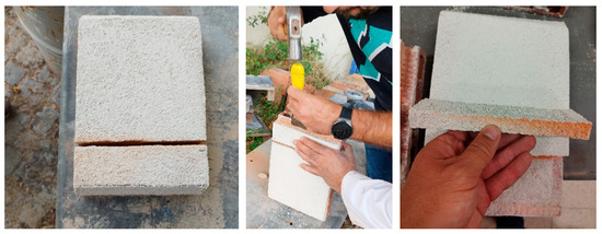
Figure 7.
Specimens’ mortar preparations for mechanical tests in laboratory.
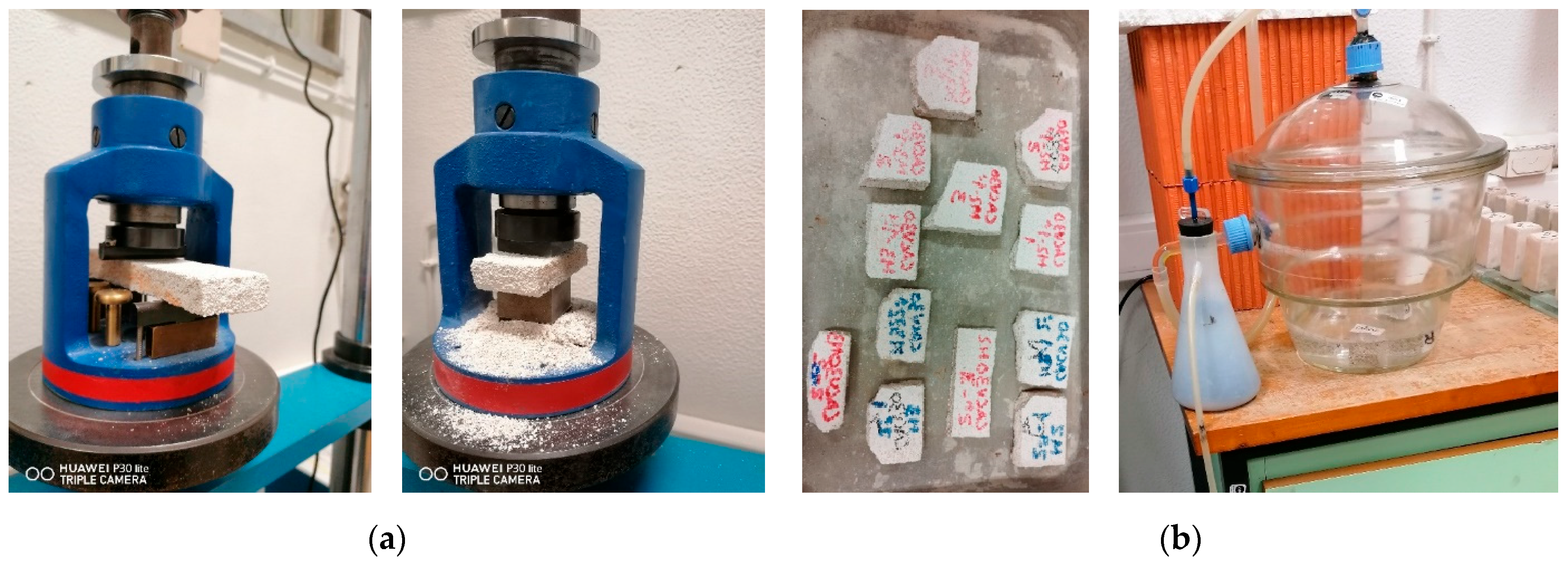
- Flexural and compressive strength tests performed to quantify the mechanical properties of the mortars were adapted from the EN 1015-11 [39] standard, using an electromechanical testing device from PROET: model ETI-HM-S/CPC, with load cells of 2 kN and 200 kN for the flexural and compressive strength, respectively. To perform these tests, at least two slices per mortar composition were used (Figure 8a), resulting in two measurements for the flexural strength, and, after the rupture, four specimens were obtained for use in the compressive strength test. Due to the traditional bricks’ smaller dimensions, the flexural strength test was only possible for the common ceramic bricks’ specimens.
 Figure 8. Tests performed in laboratory on the mortar specimens at 180 days and at the end of the exposure period: (a) flexural and compressive strength test; (b) porosity test and its sample.
 - Open porosity and apparent density of the mortars were measured to assess their compacity and estimate their water absorption capacity. This assessment is of great importance for the durability of the mortars and was determined based on EN 1936 [30], by immersion and hydrostatic weighing, using a low pressure of 40 kPa, as the pores of lime-based mortars are relatively large (Figure 8b). The test was carried out on 3 fragments of the specimens prepared for the flexural and compressive strength tests for each mortar composition.
4. Results and Discussion
4.1. The Influence of the Mortar Binder—Task 1
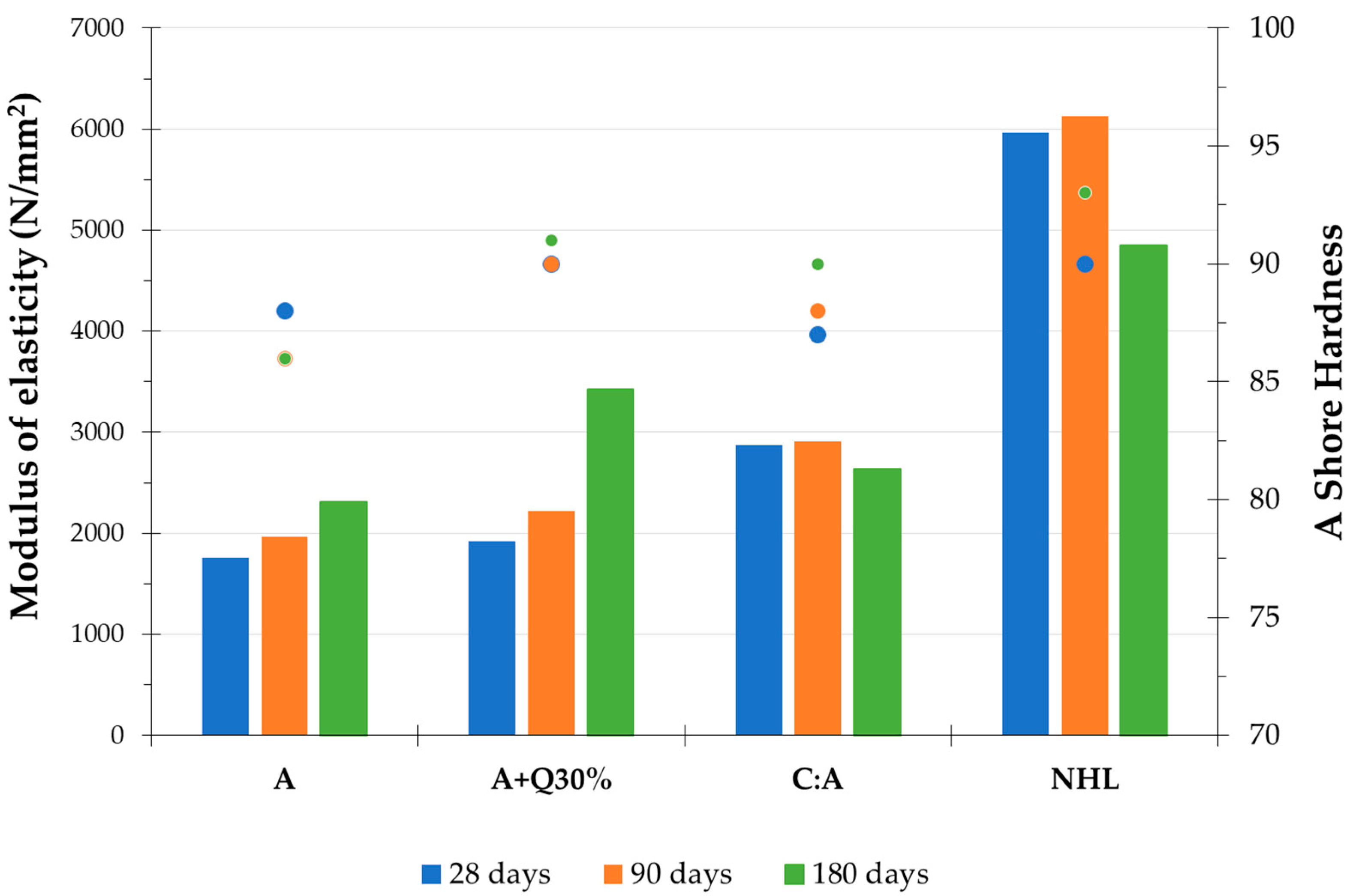
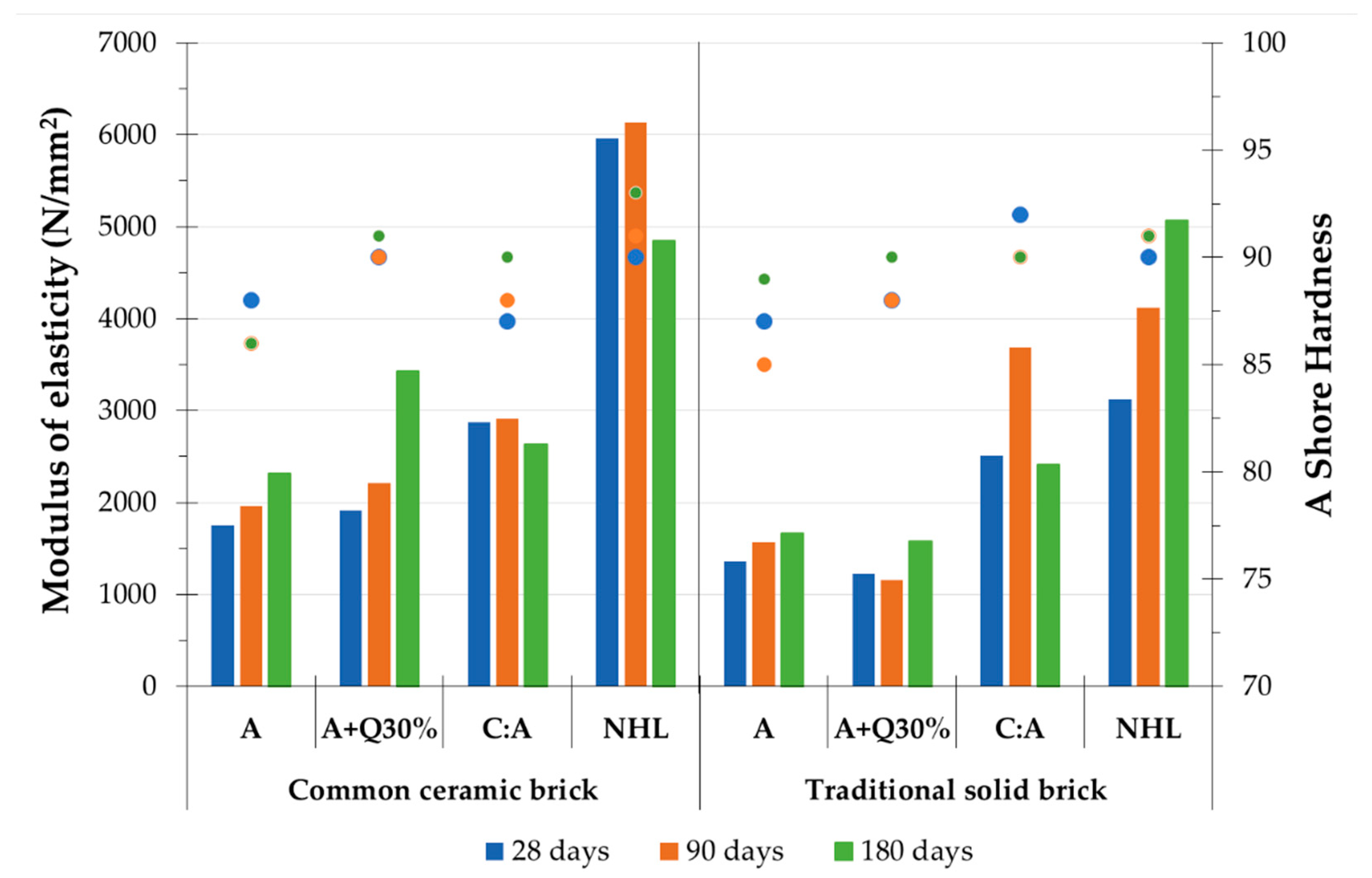
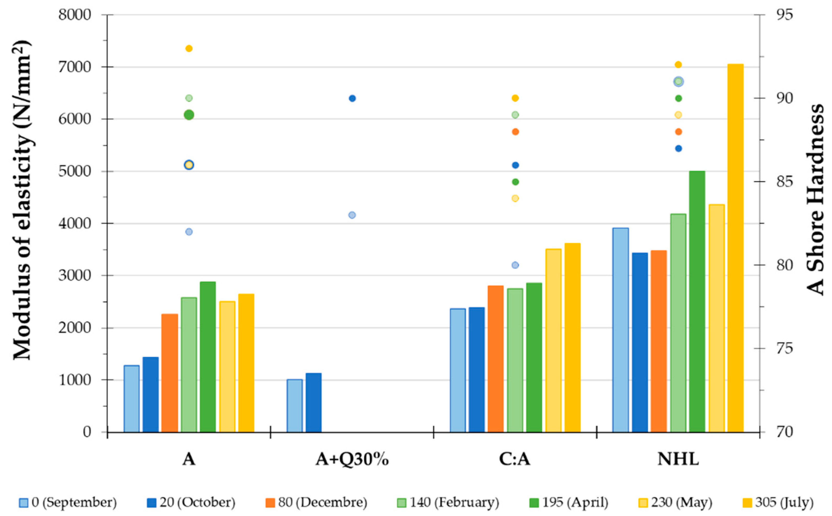
Regarding the global results obtained for the mortars applied on common ceramic bricks with moderate water absorption, along the carbonation process, at 28, 90 and 180 days (Figure 9), it was found that air lime mortars, A and A+Q30%, present moderate deformability (a modulus of elasticity between 1760 and 3430 N/mm2) and high surface hardness (86 to 91 Shore A). Additionally, these mortars show a tendency to improve their performance with the curing time.
However, mortars with some hydraulicity (C:A and NHL), despite their good performance at early ages, show a drop in their behavior at 180 days (Figure 9). Natural hydraulic lime mortar (NHL) presents the highest values (a modulus of elasticity between 4850 and 6130 N/mm2 and superficial hardness between 90 and 93 on the Shore A scale).
The physical and mechanical test results obtained at 180 days, for the reference mortar samples removed from the common ceramic bricks (Table 5), show similar trends to non-destructive tests results at the age of 28, 90 and 180 days (measurement of ultrasound propagation and surface hardness) obtained on the same applied mortars (Figure 9).
Table 5.
Test results from reference mortars applied on common ceramic bricks specimens at 180 days (average values, with standard deviation).
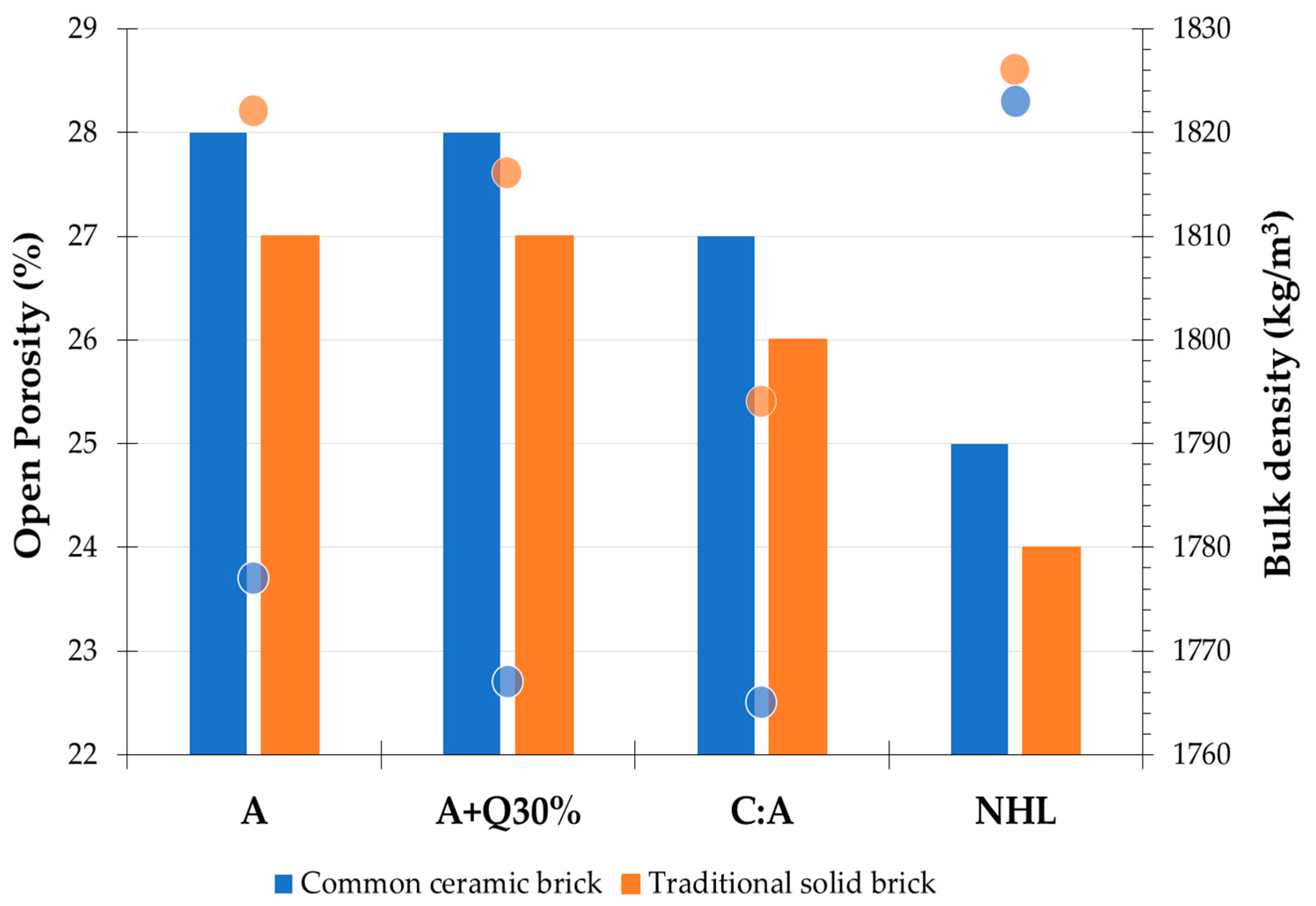
The natural hydraulic mortar (NHL) is found to be the most compact mortar, with the highest bulk density and lowest open porosity values, and, as a consequence, this mortar showed the lowest water absorption and, as a whole, the highest mechanical strengths by comparison with the other compositions. This mortar composition also presents a relative high adhesion to the substrate, with cohesive failure in the render. However, notwithstanding its good general characteristics, the relatively high modulus of elasticity can cause internal stresses on the mortar matrix that, considering the low flexural strength values of the mortar, may produce microcracking, causing a loss of mechanical characteristics and durability in the long term.
The air lime mortars (A and A+Q) present very similar porosities, densities and water absorption; however, they clearly differentiate in the mechanical strengths (Table 5). The addition of quicklime to the slaked air lime enhances the strength of the air lime mortar, with a significant increase in the compressive strength, although a slight decrease in adhesion to the medium-porous substrate (common bricks) was detected (Table 5). In fact, the expansion of quicklime on slaking fills voids, improving the microstructure and lowering shrinkage [23], which contributes to a compact structure and, consequently, improves the mortar mechanical strength. Furthermore, a high concentration of quicklime absorbs the excess water from mixing during the slaking process, which reduces the shrinkage of the lime matrix [24]. However, the heat generated during the slaking and the free water absorption by the masonry unit used as the substrate could reduce the moisture transfer from the mortar into the pore system of the substrate and, consequently, potentiate the failure on the mortar interface [23,40].

Figure 9.
Modulus of elasticity (bars) and A Shore hardness (circles) results derived from reference mortars applied on the common ceramic bricks at 28, 90 and 180 days. (Notation: unit measurement scale SHORE A from 0 to 100: 70 to 87: normal hardness; >88: very stiff [41]).
Figure 9.
Modulus of elasticity (bars) and A Shore hardness (circles) results derived from reference mortars applied on the common ceramic bricks at 28, 90 and 180 days. (Notation: unit measurement scale SHORE A from 0 to 100: 70 to 87: normal hardness; >88: very stiff [41]).
The addition of white cement to the slaked lime mortar (C:A), besides increasing the values of the modulus of elasticity and compressive strength, when compared to the pure slaked lime mortar (A), leads to a slight decrease in the adhesion to the substrate and to low values of flexural strength, since the specimens broke before the beginning of the tests (Figure 10). This behavior is attributed to some microcracking of the mortars’ matrix, since this anomaly affects flexural strength to a higher degree than compressive strength [42].
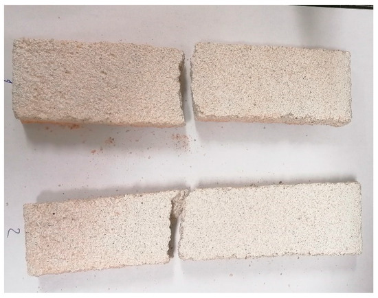
Figure 10.
Preparation of the C:A mortar specimens for the strength tests.
4.2. The Influence of the Substrate Characteristics—Task 2
The analyses carried out at 28, 90 and 180 days using ultrasound pulse propagation and surface hardness (Figure 11) show that, in general, for all mortar compositions, there is a drop in their modulus of elasticity when a very absorbent and porous substrate is used in comparison to the application on the medium-absorbent one (Figure 11). This drop is attributed to microcracking, considering that the other mechanical characteristics are not similarly affected.
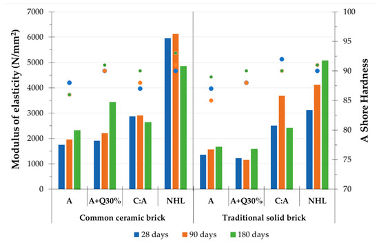
Figure 11.
Modulus of elasticity (bars) and A Shore hardness (circles) results derived from reference mortars applied on common ceramic bricks and traditional solid bricks at 28, 90 and 180 days. (Notation: unit measurement scale SHORE A from 0 to 100: 70 to 87: normal hardness; >88: very stiff [41]).
A+Q30% was the mortar composition whose behavior was the most affected by the properties of the substrate. In fact, the water available for the slaking and carbonation processes of the air lime could be quickly absorbed and at large scale by the porous substrate, which could accelerate the drying during the carbonation process, generating high stress at the interface; as a consequence, microcracking could occur, affecting the mechanical behavior of the mortar.
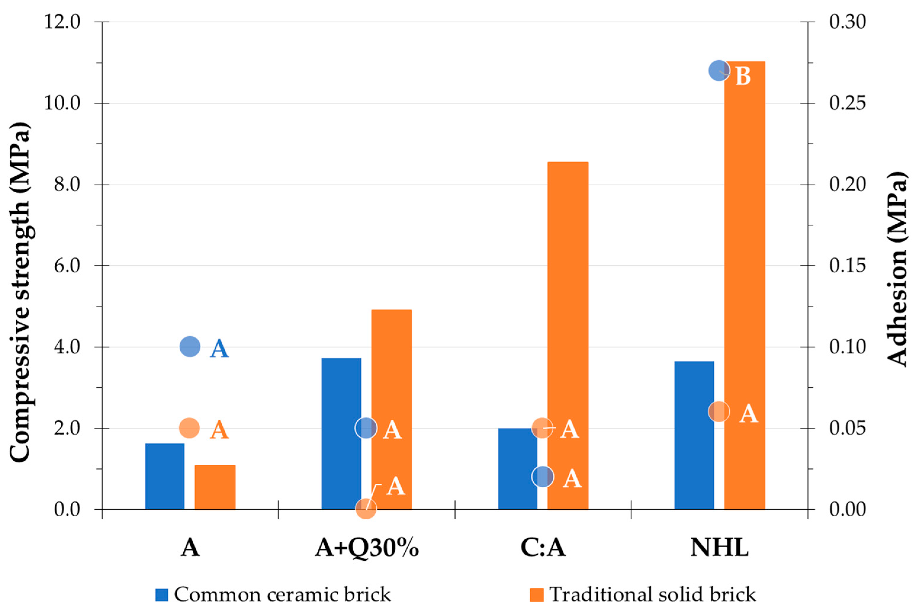
From the physical and mechanical results obtained after 180 days, it is possible to observe, as expected, that there is an increase in the bulk density and a decrease in the porosity of the mortars as the water absorption of the substrate increases (Figure 12), which means that the mortars’ structure becomes more compact, thus improving, in general, the compressive strength (Figure 13). However, the modulus of elasticity value tends to fall down (Figure 11), as well as the adhesion to the substrate (Figure 13), when the mortars are applied on very porous bricks.
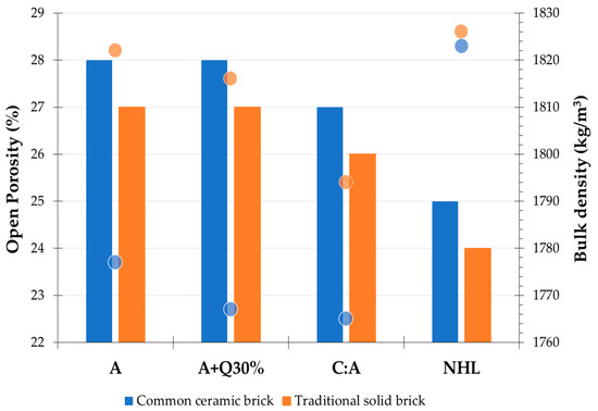
Figure 12.
Open porosity (bars) and bulk density (circles) derived from reference mortars applied on different substrates at 180 days.

Figure 13.
Compressive strength (bars) and adhesion (circles) values obtained for the reference mortars applied on different substrates at 180 days. (Notation: predominant pattern—A: adhesive failure between the substrate and the render; B: cohesive failure in the render).
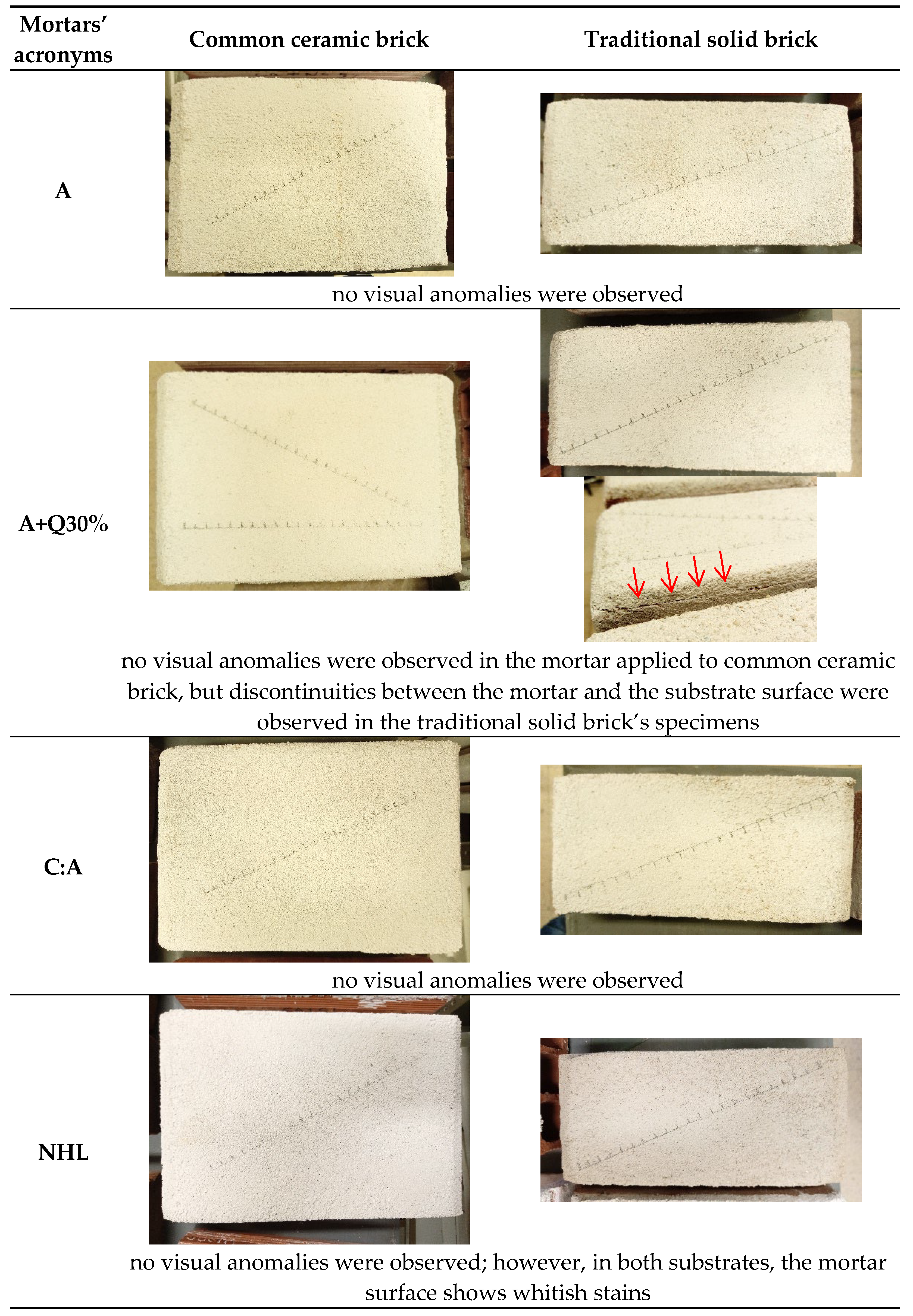
In fact, the quick absorption by the substrate may generate high stress at the interface, and therefore microcracking could occur (Figure 14). Moreover, it may also lead to a significant reduction in the water flow from the fresh mortars to the interface region of the substrate, thus weakening the effective bond, since the number of active pores, which allow for the transport of fine particles that strengthen the effective bond, is reduced [19].
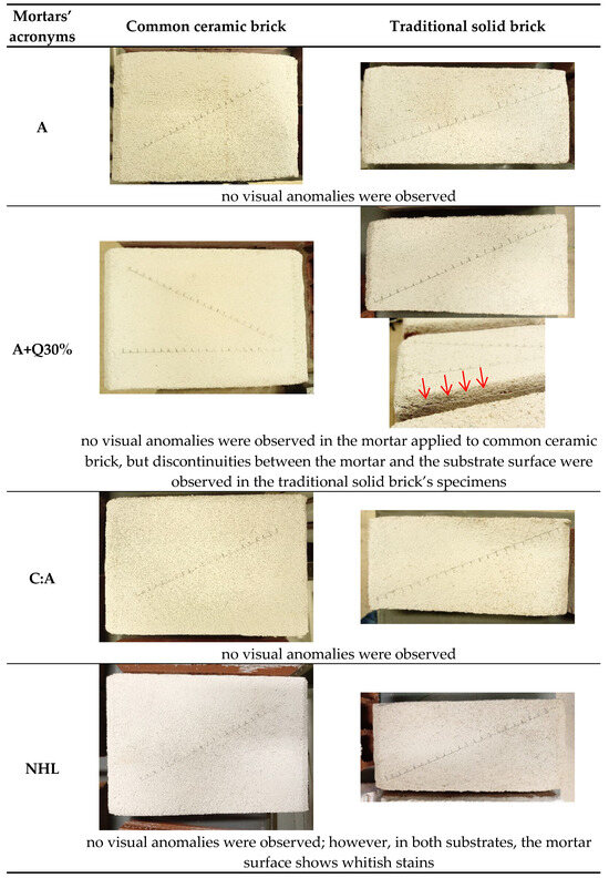
Figure 14.
Visual observations of the mortars applied to different substrates, after 180 days.
Considering the mortar compositions, despite the lower values of compressive strength, the slaked air lime mortar (A) shows a good performance when used on a very absorbent substrate, with moderate values of modulus of elasticity and tensile bond strength, which tend to improve with curing time.
A+Q30% reduces its modulus of elasticity value and adhesion significantly when applied on a very absorbent substrate, in comparison with a medium-absorbent one. However, the compressive strength consistently increases for the application on a more absorbent substrate.
Conversely, in mortars with some hydraulicity, besides the slight reduction in modulus of elasticity (Figure 11), an increase of more than 50% of the compressive strength is observed (Figure 13). The NHL mortar, in general, exhibits the highest values of mechanical strength and high values of the dynamic modulus of elasticity, which might result in incompatibility and thus compromise the durability of the ancient buildings, namely with this type of substrate. Moreover, whitish stains were visible due to the presence of soluble salts on the surface of the specimens (Figure 14) [18]. The C:A mortar, in addition to the slight reduction in modulus of elasticity, shows an improvement in the other physical and mechanical characteristics when applied on a very absorbent substrate.
4.3. The Influence of the Exposition Conditions—Task 3
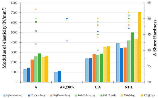
Figure 15.
Modulus of elasticity (bars) and A Shore hardness (circles) results derived from reference mortars subjected to the fort environment conditions. (Notation: SHORE A units from 0 to 100: 70 to 87: normal hardness; >88: very stiff [41]).
Table 6.
Test results after the monitorization of the reference mortars applied on mini-wallettes, subjected to the environment conditions of the fort (Fort) vs. the performance obtained at 180 days on mortars applied in laboratory with traditional solid brick (Lab).
Regarding the monitoring performed throughout the time of exposition (Figure 15), in general, all mortar compositions presented an improvement in their performance, with moderate to high values of the modulus of elasticity and high values of surface hardness (Figure 15). However, compared to the results obtained in the laboratory using the same substrate (Figure 11—traditional solid brick), the exposition to the severe marine environment, although an increment in compressive strength and decrease in permeability (Table 6) occur, reduces the modulus of elasticity values as well as the compactness, with a loss in density and increment in total porosity for all mortar compositions.
The exception is in air lime mortar compositions (A), which increase in modulus of elasticity when subjected to the severe marine environment of the fort. The enhancing of the modulus of elasticity of mortar A is probably due to the original large pores of the lime mortar matrix, which could accommodate the precipitation of salts inside and block them without producing stresses that damage the matrix [1]. On the other hand, the fine capillary pore structure of the other mortar compositions improve the compressive strength in standard conditions, while, in the fort environment conditions, if salt attack occurs, damage could be observed [43], especially in the case of sulphates (which are typically present in the maritime atmosphere, as well as chlorides), with high relative humidity values, due to the compounds that can be formed (as ettringite), that their fine porosity cannot accommodate.
Nevertheless, the severe marine environment exposition of mortars applied on a very porous substrate, in the long term, causes a decrease in the adhesion strength for air lime mortars (A and A+Q30%) and an increase for the hydraulic ones (C:A and NHL) (Table 6). In fact, this was also observed in the laboratory, where, with a very porous substrate, the A+Q30% mortar revealed adherence issues, and was even found to be detached from the substrate at early ages. The NHL mortar presents a substantial increase in the adhesion strength to a porous substrate in severe marine environment exposition, although such a difference is not evidenced in the other characteristics, such as the modulus of elasticity (Figure 11 and Figure 15), and the other physical tests (Table 6). The increase in adhesion strength in the maritime environment may be due to a higher humidity in some periods that favored the hydraulic reactions in the interface. However, NHL mortar presents low values of water permeability, shown by the Karsten tube tests, which might reduce the drying capacity of the original walls.
4.4. Improvement in the Mortar Aggregate—Task 4
Considering all the experimental campaigns in the laboratory and the in situ exposition behavior of all reference mortars studied in Tasks 1 to 3, it was decided to modify the initial formulations of two mortar compositions to improve their performance. It was also decided to make the adjustments by aligning the formulations more closely with those of the original mortars.
Two mortar compositions were chosen for this task:
- A+Q30% mortar is the closest to the original formulation [10], as well as presenting a generally good performance, with a moderate to high strength and modulus of elasticity. However, when applied on a very porous and absorbent substrate, a decrease in the adhesion to the substrate was registered, which should be analyzed in detail.
- C:A mortar has the most balanced performance, even in the aggressive environment of the fort; however, reductions in the flexural strength and in the adhesion to the substrate were observed when applied on a medium-absorbent substrate (common ceramic brick substrate).
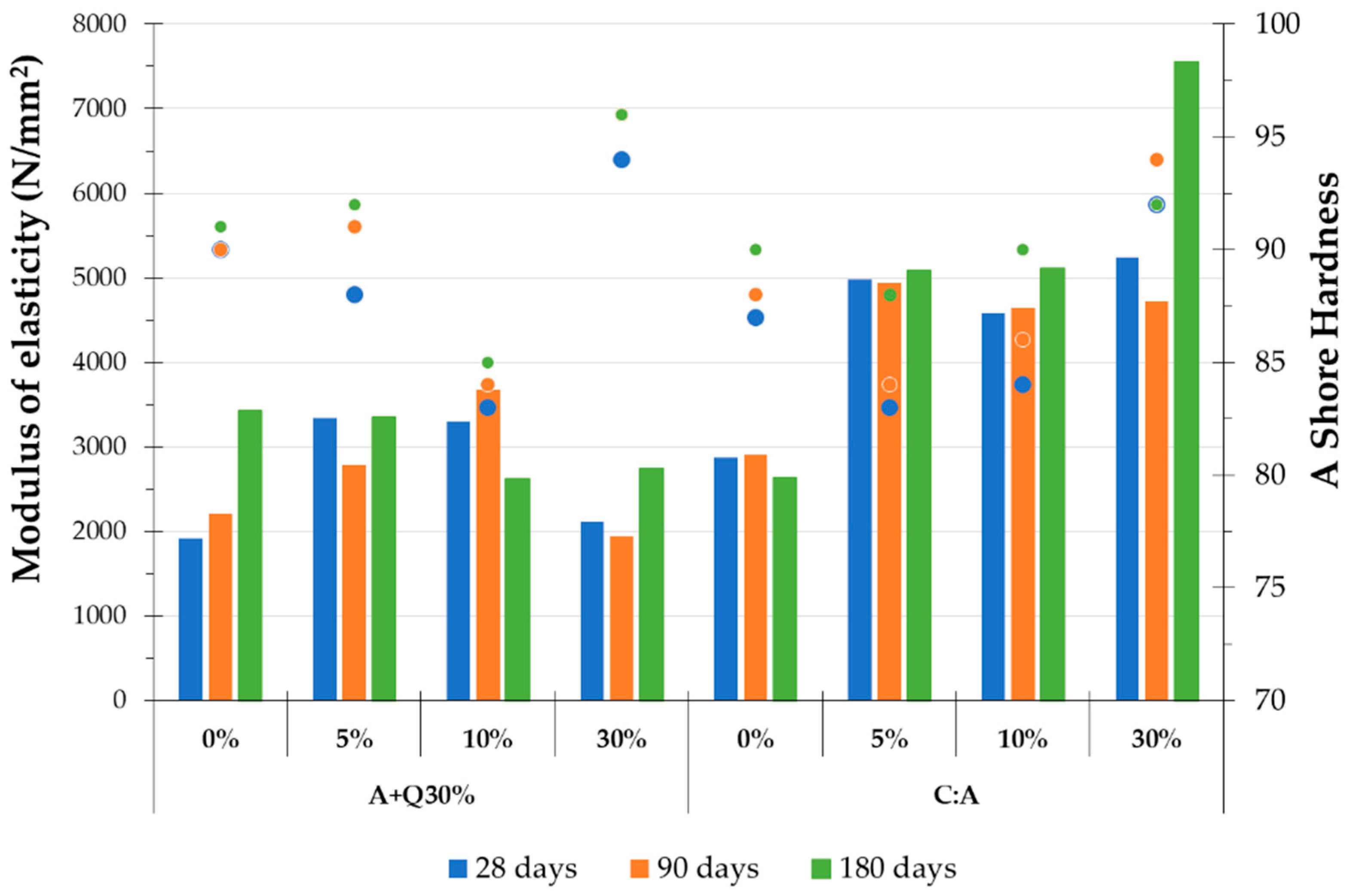
In both mortar compositions, a fine-tuning of the aggregates, substituting part of the siliceous sand with limestone aggregate at 30% (M1), 10% (M2) and 5% (M3) by volume (Table 2 and Figure 3), was performed. The mortar compositions were applied on common ceramic bricks, which show water absorption comparable to the external walls of the fort, and the main results are presented in Figure 16 and Table 7.
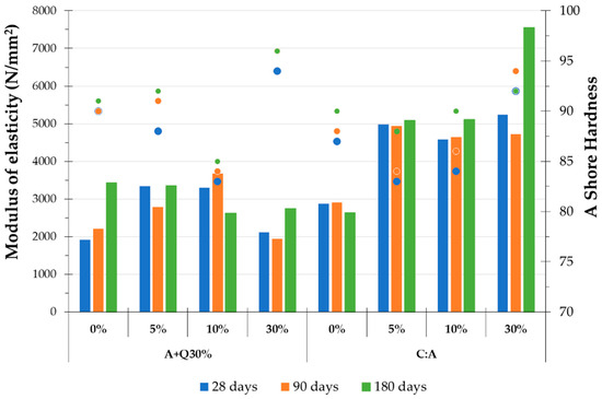
Figure 16.
Modulus of elasticity (bars) and A Shore hardness (circles) results measured in mortars, with substituting part of the silicious sand with limestone sand, applied on common ceramic bricks, at 28, 90 and 180 days. (Notation: SHORE A units from 0 to 100: 70 to 87: normal hardness; >88: very stiff [41]).
Table 7.
Tests results, at 180 days, of the mortars with partial substitution of the siliceous sand with limestone sand, applied on the common ceramic bricks.
Regarding the laboratory monitorization at 28, 90 and 180 days, it is observed that, in general, there was an increase in the modulus of elasticity for the compositions with 5% and 10% of limestone substitution (compared with the mortars with only siliceous sand) for all the mortar compositions, despite the slight decrease in surface hardness in most of the cases. However, with 30% of substitution, the increment is only observed for C:A mortar.
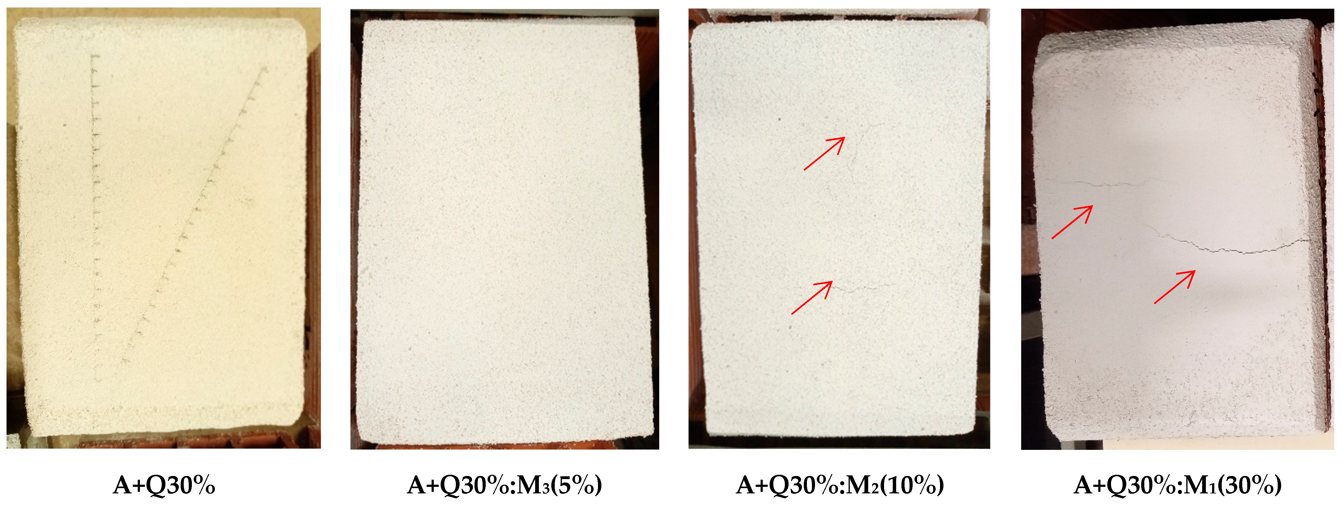
A possible explanation is that the particles of the lime binder, which are finer than the cement particles, could better fill the very small voids between the aggregates, making the mortars more compact, as can be proved by the values of bulk density (Table 7). However, for the lime mortars, the use of high contents of limestone can surpass the voids volume available, thus not contributing to improving the compactness. Moreover, mortars with a significant amount of fines in their composition, such as the A+Q30%:M1(30%) mortar, have a higher probability of microcracking [44], particularly when they are applied on a very porous substrate (Figure 17), probably due to the restricted shrinkage, decreasing their performance.
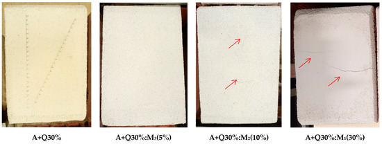
Figure 17.
A+Q30% mortars surface, where it is possible to observe cracks in A+Q30%:M1(30%) mortar and with less magnitude in A+Q30%:M2(10%).
This assumption was confirmed by the flexural strength results (which are affected by the microcracking to a higher degree than the compressive strength ones), which also reveal a decrease in their values for the A+Q30% mortar, as the content of limestone sand increases (Table 7). Conversely, the compressive strength tends to increase: this behavior is attributed to the limestone aggregates’ structure, which is similar to the calcitic binder matrix, leading to a reduction in the discontinuities between the lime matrix and the aggregates [8,45], thus contributing to the reduction in pore volume in the interfacial transition zone (ITZ), improving the compressive strength [26]. However, despite the slight increase in the adhesion strength values with 30% of substitution, compared to the reference mortars, the values of adhesion strength are low. Furthermore, the rupture pattern is adhesive between the substrate and the mortar -A. (Table 7), which means that the failure is not influenced by the mortar cohesion.
Furthermore, at 180 days (Table 7), the A+Q30% composition with 10% of limestone substitution, in comparison with 5%, in general, shows some decreases in the mechanical characteristics (modulus of elasticity, surface hardness and compressive strength), which can be attributed to microcracking, as is visible in Figure 17. However, a slight increase in the adhesion strength value is observed. On the contrary, the C:A composition with 10% of limestone substitution, besides the increase in mechanical strengths (flexural and compressive strengths), presents a substantial decrease in the adhesion strength (Table 7).
Moreover, all mortars with limestone sand show a tendency for lower water absorption (Table 7).
5. Global Discussion
According to the obtained results in this investigation, the following aspects were observed:
- (1)
- Influence of the mortar binder in different exposition conditions
- The mortar with slaked air lime (A)—the base mortar—presents relatively low strength and a high rate of water absorption. However, its characteristics tend to improve with the curing time, and they are, in general, higher in real environmental conditions, probably due to the large pore structure, which allows for the accommodation of salts without creating high stresses. This mortar composition, under laboratory conditions, presents the highest adhesion of the lime-based mortars to both substrates (common bricks and traditional very absorbent bricks). Nevertheless, a slight reduction in adherence to the substrate was observed in real conditions.
- By adding quicklime to the slaked air lime mortars (A+Q30%), an increase in the mechanical strengths is observed in comparison with A mortar; however, a low adhesion to the substrate is observed when it is applied on a very porous substrate, both in the laboratory and in in situ conditions. This mortar composition is the closest to the original formulation.
- The addition of a small amount of white cement to the slaked air lime mortars (C:A) increases the mechanical strengths, even if the open porosity values are similar to the A mortar. However, besides the satisfactory mechanical results in very porous substrates even in the aggressive environment of the fort, the adhesion to the common ceramic bricks substrate decreases by about 80% in comparison with the A mortar.
- The natural hydraulic lime mortar (NHL) shows greater mechanical strengths, even at early ages. However, the high values of the dynamic modulus of elasticity can cause internal stresses on the mortar matrix that can generate microcracking, when considering the relatively low flexural strength values obtained, namely when applied on porous and very absorbent ancient substrates. In addition, the low values of water permeability shown by the Karsten tubes tests may also induce a reduction in the drying capacity of the walls. Thus, its durability and performance in the long term could be compromised. Moreover, the presence of whitish stains at the mortar surface indicates the precipitation of salts, which, when associated with their fine pore structure, suggests a possible trend toward early degradation due to salt crystallization.
- The adjustments made in the mortar compositions, substituting part of the siliceous sand with limestone sand at 30% (M1), 10% (M2) and 5% (M3) by volume, for the mortars A+Q30% and C:A, reveal that the mortar with 30% of sand substitution (M1), in general, increases the compressive strength and adhesion and decreases the porosity and rate of water absorption for both compositions. However, these mortars suffer high shrinkage, namely the A+Q30%:M1 mortar, which leads to microcracking of the matrix, reducing the performance at a longer time. Thus, the mortars with 10% and 5% of aggregate substitution, despite some decreases in the mechanical characteristics, present the most balanced results, compatible with the original ones and with compositions closest to the original formulation.
- (2)
- Influence of the substrate characteristics
In general, under laboratory conditions, a more absorbent and porous support led to more compact mortar structures, thus incrementing the compressive strength; however, the modulus of elasticity and adhesion to the substrate tended to drop down for all mortar compositions due to a weaker interface.
- (3)
- Influence of the mortar’s expositions
Compared to the results obtained in the laboratory using the same substrate—very porous traditional solid brick—in general, the exposition to the severe marine environment, although an increment in compressive strength occurs, reduces the modulus of elasticity values, as well as the compactness, with a loss in density and increment in total porosity for all mortar compositions.
6. Conclusions
To choose the most feasible, compatible and durable repair mortars for the rehabilitation of a coastal fort, several lime-based mortar compositions were applied on two porous substrates, with different water absorptions and porosity, kept in laboratory conditions, and their main physical and mechanical characteristics were analyzed and compared. A medium-absorbent substrate was materialized by common bricks, while a very absorbent one was simulated by traditional very porous bricks. Additionally, the reference mortar compositions studied in the laboratory were also subjected to in situ conditions, and their performance in the real environment conditions of the fort was also analyzed.
The main results suggest that adding quicklime or a small amount of white cement to the slaked air lime mortar (A+Q30% and C:A, respectively) increases its mechanical strengths, with similar open porosity values to the slaked air lime mortar (A). However, the adhesion to porous substrates decreases in both cases in comparison with the A mortar.
Mortars formulated with natural hydraulic lime (NHL) show greater mechanical strengths, with high values of the dynamic modulus of elasticity and low permeability, which could compromise the durability of the original walls of the fort.
Furthermore, substituting part of the siliceous sand with limestone, closest to the original formulation, reveals that a high percentage of sand substitution (30%) enhances the mortars compressive strengths; however, these mortars suffer high shrinkage, namely when the percentage of fine particles increases, thus leading to microcracking of the matrix, reducing the performance at a longer time. Lower percentages of sand substitution (5% and 10%) present the most balanced results; despite the slight reduction in the compressive strength compared to the reference mortars, these compositions should be analyzed in detail in further studies, as they can be adequate solutions.
Additionally, the mortar application in the more absorbent and porous substrate, similar to the ceiling vaults of the interior of the fort, led to more compact mortar structures, which improved the compressive strength; however, in general, the modulus of elasticity and the adhesion to the substrate tend to drop for all mortar compositions.
Therefore, in this particular case study, where additional mechanical strength with a moderate modulus of elasticity and some water permeability is needed, due to the severe marine environment, the A+Q30% mortar seems to be a balanced solution for the medium-absorbent substrate. Thus, it is recommended for the restoration work of the external walls of the fort, since the exterior stone walls were found to have moderate to low water absorption and the external environmental conditions require significant mechanical resistance. This composition presents higher strength than the other lime-based mortar compositions, with moderate deformability, to accommodate stresses that might occur within the substrate without failing. Moreover, it presents a continuous performance evolution during the carbonation process, which indicates that no significant cracking occurs. Additionally, it is the closest to the original formulation.
However, this composition presents low values of adherence when it is used on very porous and absorbent substrates; thus, it is not recommended for the interior of the fort, which presents vaults of very porous ceramic bricks. For this localization, the solution of slaked air lime mortar (A) is recommended, also taking into account that it will not be exposed to rain and strong wind, and so a very high mechanical strength is not needed.
Author Contributions
A.R.S., M.d.R.V. and A.S.S. conceived the formulations and all the parameters of the study; A.R.S. performed the experiments in the laboratories of Portuguese National Laboratory for Civil Engineering; A.R.S. and M.d.R.V. analyzed and discussed the laboratory and in situ test results; M.d.R.V. and A.S.S. analyzed and discussed the characterization of the original mortars; M.d.R.V. and A.S.S. were responsible for the supervision of the research; writing—original draft preparation was performed by A.R.S., and the review and editing were performed by M.d.R.V., A.S.S. and A.R.S.; M.d.R.V. was responsible for the funding acquisition. All authors have read and agreed to the published version of the manuscript.
Funding
Programme Cultural Entrepreneurship, Cultural Heritage and Cultural Cooperation of European Economic Area (EEA) grants, Culture Programme 2014–2021, within the scope of the “Coastal Memory Fort” project (Project Number: PT-CULTURE-0003), and National Laboratory of Civil engineering within the scope of the “MICR-Integrated Methods for Conservation and Rehabilitation of Built Heritage” (grant number 0803/1102/24170).
Data Availability Statement
The data presented in this study are available on request from the corresponding author.
Acknowledgments
The authors wish to thank LNEC technicians for their collaboration in carrying out the tests (especially to Bento Sabala), and the collaboration of Lhoist Portugal, Secil Argamassas and Lena Agregados in supplying the testing materials, as well as the support and collaboration of Lourinhã Municipality. This work is a contribution to the EEA Grants Culture Programme 2014–2021 “Coastal Memory Fort—Paimogo Fort”.
Conflicts of Interest
The authors declare no conflicts of interest.
Note
| 1 | The time found for the reaction temperatures to get lower than 75 ± 5 °C, allowing for a safe mixing of the mortar. |
References
- Borges, C.; Santos Silva, A.; Veiga, M.R. Durability of ancient lime mortars in humid environment. Constr. Build. Mater. 2014, 66, 606–620. [Google Scholar] [CrossRef]
- Van Balen, K.; Papayianni, I.; Van Hees, R.; Binda, L.; Waldum, A. RILEM TC 167-COM report—Introduction to requirements for and functions and properties of repair mortars. Mater. Struct. 2005, 38, 781–785. [Google Scholar] [CrossRef]
- TC 203-RHM (Main author: Caspar Groot). Repair mortars for historic masonry: Performance requirements for renders and plasters. Mater. Struct. 2012, 45, 1277–1285. [Google Scholar] [CrossRef]
- Veiga, M.R.; Fragata, A.; Velosa, A.; Magalhães, A.C.; Margalha, G. Lime-based mortars: Viability for use as substitution renders in historical buildings. Int. J. Archit. Herit. 2010, 4, 177–195. [Google Scholar] [CrossRef]
- Groot, C.; Gunneweg, J. Choosing mortars compositions for repoint mortars of historic masonry under severe environmental conditions. In Proceedings of the HMC2013—3rd Historic Mortar Conference, Glasgow, UK, 11–14 September 2013. [Google Scholar]
- Travincas, R.; Torres, I.; Flores-Colen, I.; Francisco, M.; Bellei, P. The influence of the substrate type on the performance of an industrial cement mortar for general use. J. Build. Eng. 2023, 73, 106784. [Google Scholar] [CrossRef]
- Lubelli, B.; Van Hees, R.; Groot, C. The Effect of Environmental Conditions on Sodium Chloride Damage. Stud. Conserv. 2006, 51, 41–56. [Google Scholar] [CrossRef]
- Arizzi, A.; Cultrone, G. The difference in behavior between calcitic and dolomitic lime mortars set under dry conditions: The relationship between textural and physical-mechanical properties. Cem. Concr. Res. 2012, 42, 818–826. [Google Scholar] [CrossRef]
- Groot, C.; Veiga, M.R.; Papayianni, I.; Van Hees, R.; Secco, M.; Alvarez, J.I.; Faria, P.; Stefanidou, M. RILEM TC 277-LHS report: Lime-based mortars for restoration—A review on long-term durability aspects and experience from practice. Mater. Struct. 2022, 55, 245. [Google Scholar] [CrossRef]
- Veiga, M.R.; Aguiar, J. Rehabilitation of S. Bruno Fort. Notes on the Results of the Collaboration Provided by LNEC to CMO (Reabilitação do Forte de S. Bruno; Notas Sobre os Resultados da Colaboração Prestada pelo LNEC à CMO); IV Encontro Nacional de Municípios com Centro Histórico: Oeiras, Portugal, 1996. (In Portuguese) [Google Scholar]
- Pringopoulos, T.A.; Thomoglou, A.K.; Fantidis, J.G.; Thysiadou, A.A.; Metaxa, Z.S. Advanced Lime Mortars for Historical Architectural Structures. Eng. Proc. 2024, 70, 58. [Google Scholar] [CrossRef]
- Maravelaki, P.N.; Kapetanaki, K.; Papayianni, I.; Ioannou, I.; Faria, P.; Alvarez, J.I.; Stefanidou, M.; Nunes, C.; Theodoridou, M.; Ferrara, L.; et al. RILEM TC 277-LHS report: Additives and admixtures for modern lime-based mortars. Mater. Struct. 2023, 56, 106. [Google Scholar] [CrossRef]
- Veiga, M.R.; Velosa, A.; Magalhães, A.C. Experimental applications of mortars with pozzolanic additions. Characterization and performance evaluation. Constr. Build. Mater. 2009, 23, 318–327. [Google Scholar] [CrossRef]
- Veiga, M.R.; Magalhães, A.C. Substitution External Rendering of São Jorge dos Oitavos Fortress, in Cascais: Selection of the Rendering Solution (Revestimentos Exteriores de Substituição do Forte dos Oitavos em Cascais: Selecção da Solução de Revestimento); Report LNEC 72/2006—DED/NRI; LNEC: Lisboa, Portugal, 2006. (In Portuguese) [Google Scholar]
- Veiga, M.R.; Santos Silva, A.; Marques, A.I.; Sabala, B. Characterization of Existing Mortars of the Fort of Nossa Senhora dos Anjos do Paimogo (Caracterização das Argamassas Existentes no Forte de Nossa Senhora dos Anjos do Paimogo); Report LNEC 67/2022—DED/NRI; LNEC: Lisboa, Portugal, 2022. (In Portuguese) [Google Scholar]
- Nossa Senhora dos Anjos de Paimogo Fort (Forte no Lugar de Paimogo/Forte de Nossa Senhora dos Anjos de Paimogo). Available online: http://www.monumentos.gov.pt/Site/APP_PagesUser/SIPA.aspx?id=6327 (accessed on 9 January 2023). (In Portuguese)
- Cruz, J.; Menezes, M.; Tomás, C.; Antunes, V. The Memories Fort (Paimogo-Lourinhã)—A case of safeguarding material and immaterial heritage (O Forte das Memórias (Paimogo-Lourinhã)—Um caso de salvaguarda do património material e imaterial). In Proceedings of the I Jornadas de Sociologia do Turismo da Associação Portuguesa de Sociologia, Faro, Portugal, 7–9 April 2022; pp. 15–16. (In Portuguese). [Google Scholar]
- Santos, A.R.; Veiga, M.R.; Santos Silva, A. Characterization and Assessment of Performance of Innovative Lime Mortars for Conservation of Building Heritage: Paimogo’s Fort, a Case Study. Appl. Sci. 2023, 13, 4679. [Google Scholar] [CrossRef]
- Santos, A.R.; Veiga, M.R.; Santos Silva, A.; de Brito, J. Tensile bond strength of lime-based mortars: The role of the microstructure on their performance assessed by a new non-standard test method. J. Build. Eng. 2020, 29, 101136. [Google Scholar] [CrossRef]
- EN 459-1; Building Lime; Part 1: Definitions, Specifications and Conformity Criteria. European Committee for Standardization (CEN): Brussels, Belgium, 2015.
- Veiga, M.R. Air lime mortars: What else do we need to know to apply them in conservation and rehabilitation interventions? A review. Constr. Build. Mater. 2017, 157, 132–140. [Google Scholar] [CrossRef]
- Forster, A. Hot-Lime Mortars: A Current Perspective. J. Archit. Conserv. 2004, 10, 7–27. [Google Scholar] [CrossRef]
- Magalhães, A.C.; Muñoz, R.; Oliveira, M.M. The use of a mixture of quicklime and slaked lime in old mortars: The Loriot method (O uso da mistura de cal viva e cal extinta nas argamassas antigas: O método Loriot). In Proceedings of the HCLB—I Congresso Internacional de História da Construção Luso-Brasileiro, Vitória, Brazil, 4–6 September 2013. (In Portuguese). [Google Scholar]
- Loriot, A. 1716-1782—Memoir on a Discovery in the Art of Building (Mémoire sur une Découverte dans l’art de bâtir); De L’imprimerie de Michel Lambert: Paris, France, 1774; Available online: https://archive.org/details/mmoiresurunedcou00lori/mode/2up (accessed on 9 January 2023). (In French)
- EN 197-1; Cement; Part 1: Composition, Specifications and Conformity Criteria for Common Cements. European Committee for Standardization (CEN): Brussels, Belgium, 2011.
- Santos, A.R.; Veiga, M.R.; Silva, A.S.; de Brito, J.; Álvarez, J.I. Evolution of the microstructure of lime based mortars and influence on the mechanical behaviour: The role of the aggregates. Constr. Build. Mater. 2018, 187, 907–922. [Google Scholar] [CrossRef]
- EN 1015-2; Methods of Test for Mortar for Masonry; Part 2: Bulk Sampling of Mortars and Preparation of Test Mortars. European Committee for Standardization (CEN): Brussels, Belgium, 1998.
- EN 16302; Conservation of Cultural Heritage; Test Methods: Measurement of Water Absorption by Pipe Method. European Committee for Standardization (CEN): Brussels, Belgium, 2013.
- EN 772-11; Methods of Test for Masonry Units; Part 11: Determination of Water Absorption of Aggregate Concrete, Autoclaved Aerated Concrete, Manufactured Stone and Natural Stone Masonry Units Due to Capillary Action and the Initial Rate of Water Absorption of Clay Masonry Units. European Committee for Standardization (CEN): Brussels, Belgium, 2011.
- EN 1936; Natural Stone Test Methods; Determination of Real Density and Apparent Density, and of Total and Open Porosity. European Committee for Standardization (CEN): Brussels, Belgium, 2006.
- Climatic Conditions Recorded in Areia Branca Beach: Temperature, Precipitation, Wind Speed. Available online: https://www.windguru.cz (accessed on 27 July 2023).
- ISO 7619-1; Rubber, Vulcanized or Thermoplastic—Determination of Indentation Hardness—Part 1: Durometer Method (Shore Hardness). International Organization for Standardization (ISO): Geneva, Switzerland, 2010.
- ASTM D2240-15; Standard Test Method for Rubber Property-Durometer Hardness. American Society for Testing and Materials (ASTM): West Conshohocken, PA, USA, 2021.
- Fioretti, G.; Andriani, G.F. Ultrasonic wave velocity measurements for detecting decay in carbonate rocks. Q. J. Eng. Geol. Hydrogeol. 2018, 51, 179–186. [Google Scholar] [CrossRef]
- EN 12504-4; Testing Concrete in Structures; Part 4: Determination of Ultrasonic Pulse Velocity. European Committee for Standardization (CEN): Brussels, Belgium, 2004.
- RILEM. Test No. III.2, Determination of the dynamic modulus of elasticity pulse velocity. Mater. Struct.—Res. Test. 1980, 13, 219–221. [Google Scholar]
- Marques, A.I.; Morais, J.; Morais, P.; Veiga, M.R.; Santos, C.; Candeias, P.X.; Ferreira, J.G. Modulus of elasticity of mortars: Static and dynamic analyses. Constr. Build. Mater. 2020, 232, 117216. [Google Scholar] [CrossRef]
- EN 1015-12; Methods of Test for Mortar for Masonry; Part 12: Determination of Adhesive Strength of Hardened Rendering and Plastering Mortars on Substrates. European Committee for Standardization (CEN): Brussels, Belgium, 2016.
- EN 1015-11; Methods of Test for Mortar for Masonry; Part 11: Determination of Flexural and Compressive Strength of Hardened Mortar. European Committee for Standardization (CEN): Brussels, Belgium, 1999.
- Hughes, J.; Taylor, A.K. Compressive and flexural strength testing of brick masonry panels constructed with two contrasting traditionally produced lime mortars. In Workshop Repair Mortars for Historic Masonry; Groot, C., Ed.; RILEM Publications SARL: Marne la Vallée, France, 2009; pp. 162–177. ISBN 978-2-35158-083-7. [Google Scholar]
- Tavares, M. The Conservation and Restoration of Old Buildings Renderings—A Methodology for Study and Repair (A Conservação e o Restauro de Revestimentos Exteriores de Edifícios Antigos—Uma Metodologia de Estudo E Reparação). Ph.D. Thesis, Faculty of Architecture, Technical University of Lisbon, Lisbon, Portugal, November 2009. (In Portuguese). [Google Scholar]
- Arandigoyen, M.; Alvarez, J.I. Pore structure and mechanical properties of cement-lime mortars. Cem. Concr. Res. 2007, 37, 767–775. [Google Scholar] [CrossRef]
- Lanas, J.; Sirera, R.; Alvarez, J.I. Study of the mechanical behaviour of masonry repair lime-based mortars cured and exposed under different conditions. Cem. Concr. Res. 2006, 36, 961–970. [Google Scholar] [CrossRef]
- Veiga, M.R.; Santos, A.R.; Santos, D. Natural hydraulic lime mortars for rehabilitation of old buildings: Compatibility and performance. In Proceedings of the Conference and Gathering of the Building Limes Forum 2015, Building Limes Forum, Cambridge, UK, 18–20 September 2015. [Google Scholar]
- Lanas, J.; Alvarez, J.I. Masonry repair lime-based mortars: Factors affecting the mechanical behavior. Cem. Concr. Res. 2003, 33, 1867–1876. [Google Scholar] [CrossRef]


Disclaimer/Publisher’s Note: The statements, opinions and data contained in all publications are solely those of the individual author(s) and contributor(s) and not of MDPI and/or the editor(s). MDPI and/or the editor(s) disclaim responsibility for any injury to people or property resulting from any ideas, methods, instructions or products referred to in the content. |
© 2025 by the authors. Licensee MDPI, Basel, Switzerland. This article is an open access article distributed under the terms and conditions of the Creative Commons Attribution (CC BY) license (https://creativecommons.org/licenses/by/4.0/).