Article

Pendulum Mill: The Lifelong Project of Leonardo da Vinci

by
Lorenzo Fiorineschi
1,*,
Federico Rotini
1 and
Roberta Barsanti
2
1
Department of Industrial Engineering, University of Florence, 50139 Firenze, Italy
2
Museo Leonardiano, 50059 Vinci, Italy
*
Author to whom correspondence should be addressed.
Heritage 2025, 8(12), 497; https://doi.org/10.3390/heritage8120497
Submission received: 24 September 2025 / Revised: 19 November 2025 / Accepted: 21 November 2025 / Published: 24 November 2025

Abstract

This study investigates Leonardo da Vinci’s long-standing interest in milling technologies through the digital reconstruction of a pendulum-driven mill illustrated in the Codex Atlanticus. By tracing the chronological development of Leonardo’s ideas across multiple sheets, this research highlights the continuity and evolution of his conceptual approach to energy transmission and mechanical automation. This work adopts a systematic design methodology to interpret and visualize the structural logic of the machine, integrating historical sources with engineering reasoning. The resulting CAD model reconstructs the key components (such as the gear train, escapement system, and pendulum) within a coherent architectural framework inspired by Leonardo’s sketches. While the digital model remains a preliminary interpretation, it offers a historically grounded basis for future refinements. In particular, it lays the groundwork for potential physical reconstructions intended for museum display and public engagement. This study contributes to the broader understanding of Renaissance mechanical culture and the role of digital tools in heritage preservation and dissemination.

1. Introduction

The study of historical machinery offers a unique window into the technological ingenuity of past eras. Among the most intriguing examples is a particular version of Leonardo da Vinci’s pendulum mill, i.e., a design that stands out for its unconventional approach to harnessing energy and converting oscillatory motion into rotational work. The most evolved design from Leonardo is documented primarily in the Codex Atlanticus (sheet 170r), and in form of earliest sketch in the Codex Forster I (sheet 46r). This device exemplifies Leonardo’s deep engagement with mechanical innovation during the Renaissance. Indeed, while traditional mills of the time largely relied on steady water or wind power, the pendulum mill represents an early exploration into dynamic systems, one that hints at the principles of regulated motion and energy storage.
Leonardo’s extensive notebooks, which include thousands of pages of sketches and technical notes, reveal his fascination with improving the efficiency and functionality of industrial machinery [1,2]. In his studies of watermills, for example, he paid close attention to gear ratios, weight distribution, and the flow of energy. Concerns that are clearly reflected in the detailed transmission ratios, material references, and dimensioning noted on sheet 170r of the Codex Atlanticus [3,4]. These documents demonstrate that Leonardo not only observed the functioning of conventional mills but also sought to reimagine their underlying principles by incorporating elements of oscillatory motion.
The pendulum mill, as inferred from these manuscripts, appears to be an ambitious and somewhat speculative design. Its distinctive feature is the integration of a pendulum, i.e., a mechanism known for its periodic motion, to drive the milling process. Although the design lacks explicit textual explanations for every single component, the overall concept suggests that Leonardo was exploring ways to achieve a more controlled and perhaps even self-regulating power source. Such a concept is particularly striking given that Leonardo’s work predates the full scientific articulation of pendulum dynamics, which would later become central to clockmaking and precision engineering [5].
Beyond its technical merits, the pendulum mill can be viewed within a broader historical and cultural context. Renaissance Italy, particularly in regions like Vinci and the surrounding Tuscan countryside, was a hotbed of mechanical innovation. Mills were ubiquitous and critical to the local economy, serving not only as tools for processing grain but also as symbols of human ingenuity in harnessing natural forces. It is likely that Leonardo’s personal background, i.e., a childhood spent in a region where mills were integral to daily life, contributed significantly to his interest in these machines. His father, Ser Piero da Vinci, was involved in local administrative and economic activities that often intersected with mill operations, providing young Leonardo with early exposure to the practical challenges and potentials of mechanical power [6].
Moreover, the broader technological environment of the Renaissance was marked by systematic efforts to document and improve mechanical devices. The treatises of engineers like Taccola (also known as Mariano di Jacopo) and Francesco di Giorgio Martini, demonstrate attention to optimizing power transmission and automating processes in milling technology [7,8].
The significance of Leonardo’s pendulum mill lies not only in its technical details but also in its broader implications for the evolution of mechanical design. The integration of oscillatory motion into a milling system represents an early attempt to transcend the limitations of conventional energy sources. While traditional mills were subject to the variability of water flow or wind intensity, a pendulum-driven mechanism offers the potential for more regular and predictable operations, disregarding from the availability of these energy resources. This idea, although not actually realized in Leonardo’s time, foretells later developments in mechanical regulation and even concepts related to perpetual motion, i.e., a topic that fascinated many Renaissance thinkers despite its eventual refutation by modern physics.
Therefore, the pendulum-driven mill was selected in this study because it represents one of Leonardo’s most conceptually sophisticated mechanical inventions, where gravitational regulation and continuous rotary transmission coexist in a single integrated system. Unlike most of his other mill designs, comprehensive studies about this gigantic machine currently lack, despite Leonardo developed it through the different phases of his life.
More precisely, this study is dedicated to a comprehensive analysis of the pendulum mill of Leonardo da Vinci, with a systematic interpretation of the data available. Starting by examining information from the Codex Atlanticus (especially from Sheet 170r), this work aims to elucidate the technical principles underlying the design. By taking inspiration from a systematic method available in the literature [9], specifically developed for interpreting ancient machines and borrowed from the field of Engineering Design, this investigation primary aims at providing a high-fidelity virtual model of the Pendulum mill.
To clearly describe the work, this paper has been structured as it follows.
In Section 2, the chronological evolution of the concept of the pendulum mill is described, in order to identify the main relevant documents, besides the sheet 170r of the Codex Atlanticus. Then, in Section 3 an in-depth analysis of the available information is reported, together with a short illustration of the systematic approach followed for selecting the technical details needed for the 3D model reconstruction. In Section 4, the main details of the Computer Aided Design (CAD) 3D model are presented and explained. In Section 5, Discussions are reported, by focusing on the achieved results, the main limitations of the work described in this paper, as well as the impact expected for Academia and Society. Eventually, Section 6 is devoted to Conclusions.

2. Evolution of the Concept

The mill represents a structure deeply intertwined with the territory of Vinci and the era of Leonardo da Vinci. Between the Middle Ages and the Renaissance, the region was dotted with numerous mills powered by the waterways that once crisscrossed the landscape. Even today, many remnants of these mills remain. Mills held a special significance for Leonardo and his native land. It is likely that mills were among the first machines Leonardo encountered in his youth. In fact, Leonardo had dealings with a family-owned mill, as documented in a record that details the concession of a mill owned by the Municipality of Vinci to Francesco di Antonio da Vinci, Leonardo’s uncle, who acted on behalf of his brother Ser Piero, Leonardo’s father [6]. The concession allowed the mill to pass to either legitimate or natural descendants upon the original grantee’s death. Although the grant would automatically transfer to legitimate heirs, Francesco seemed concerned about Leonardo’s future, ensuring a clause was included to allow the concession to pass to Ser Piero’s “illegitimate son,” Leonardo, in the absence of legitimate heirs. This clause was not renewed in subsequent records, as Ser Piero later fathered many legitimate children. Nevertheless, it is noteworthy that Leonardo was present at the drafting of this document [10].
Given Leonardo’s connection to mills, it is essential to contextualize the Pendulum Mill within the Renaissance, a period marked by the search for new sources of mechanical power. During this time, debates on perpetual motion were particularly lively, and Leonardo himself engaged deeply in these discussions. However, the pursuit of an alternative energy source for mills was not merely a philosophical endeavor. It also addressed practical challenges, such as seasonal droughts and the properties of flour. Even today, summer droughts are common in the Vinci region, which was once abundant in water mills. Furthermore, flour, unlike grain or oil, does not preserve well, necessitating the continuous operation of mills even in the dry season. It is plausible, therefore, to hypothesize that Leonardo’s exploration of alternative power sources was a practical response to the recurring issue of drought in his homeland.
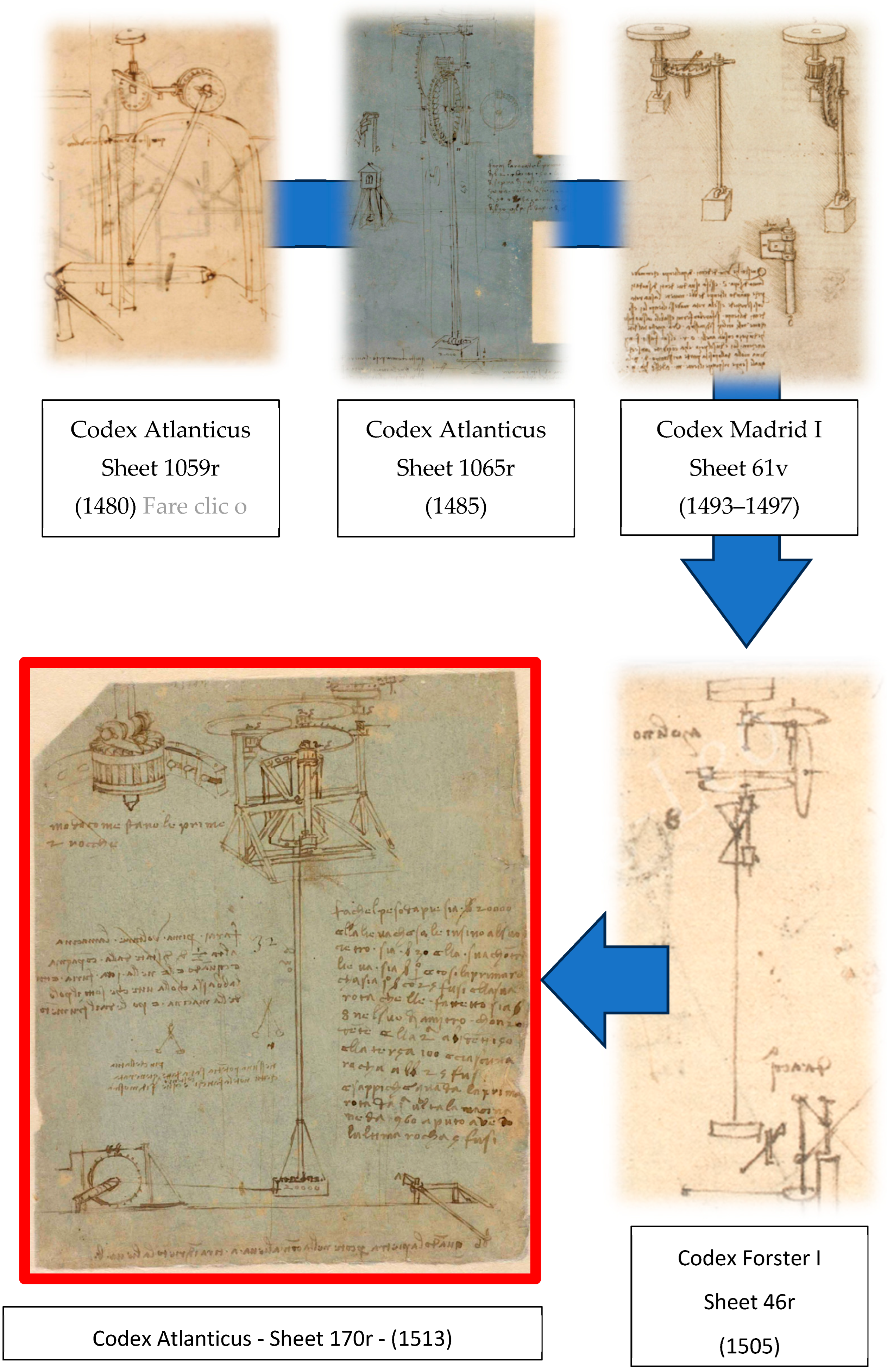
However, the reference sheet (Codex Atlanticus, Sheet 170r) featured in this study is not the first Pendulum Mill conceived by Leonardo. Rather, it represents the culmination of a long trajectory of research (see Figure 1). The following paragraphs will present a historical overview of Leonardo’s Pendulum Mill concepts, delve into the theme of perpetual motion, and examine how it may have influenced Leonardo’s thinking.
The dating of sheets from the Codex Atlanticus was established by Pietro Marani and Carlo Pedretti and can be found in the LeonardoTheka of the Museo Galileo [11]. Dates for other codices were sourced from the “Carte Leonardiane” project [12], which provides information on dating, authorship, and relevant sources. In some cases, the dating is presented as a range, reflecting the inherent difficulty in pinpointing exact creation dates.
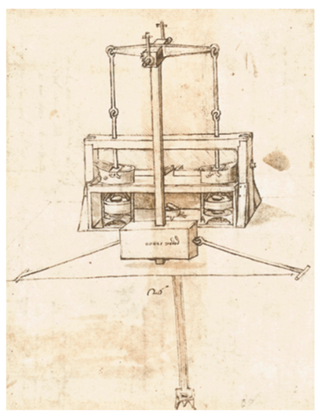
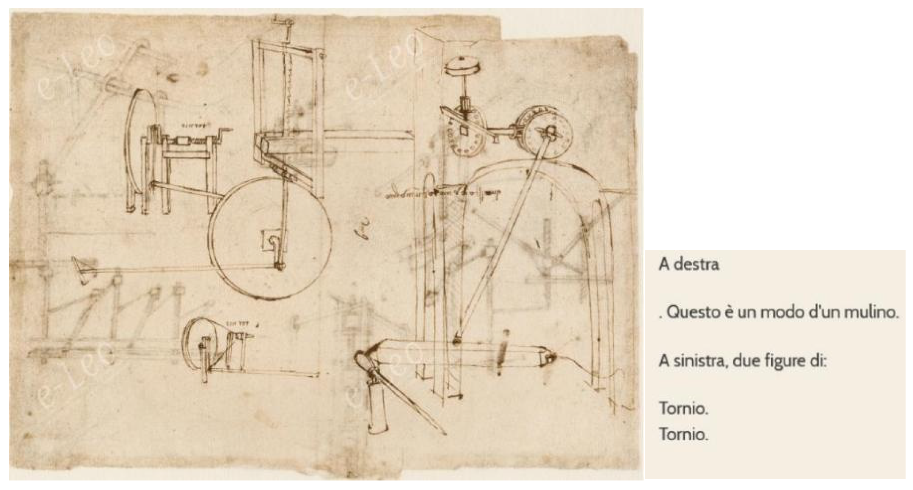
Referring to Figure 1, it is possible to observe that Leonardo’s earliest concept of the Pendulum Mill appears on sheet 1059r of the Codex Atlanticus [13], dated to 1480 [11].
This initial concept features a stone structure and a component resembling a lever designed to push the oscillating mass. However, the brief text accompanying the drawing offers limited insight into the actual machine’s function.
Figure 1. Chronological evolution of the idea of the pendulum mill in Leonardo’s life [13,14,15].
Heritage 08 00497 g001
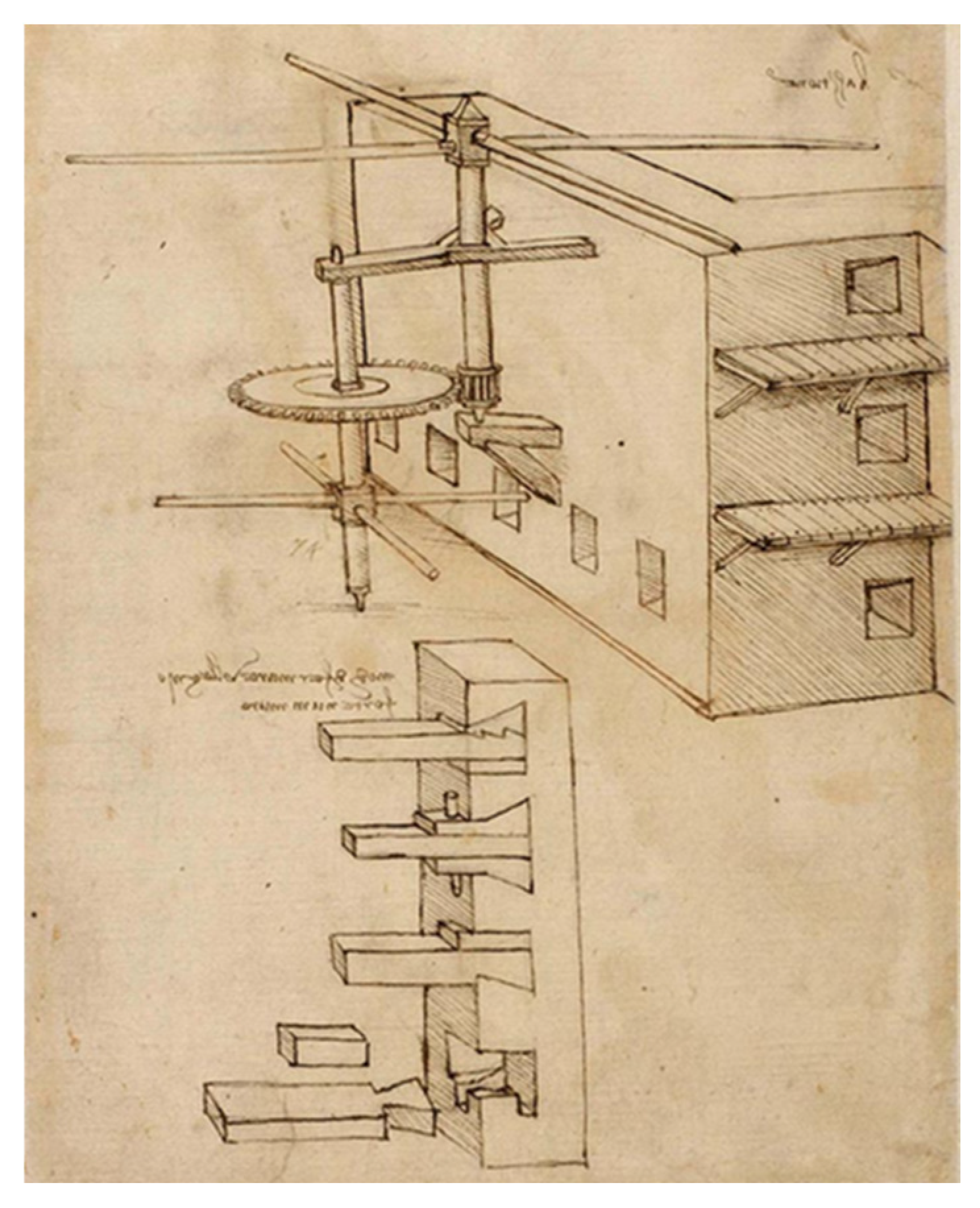
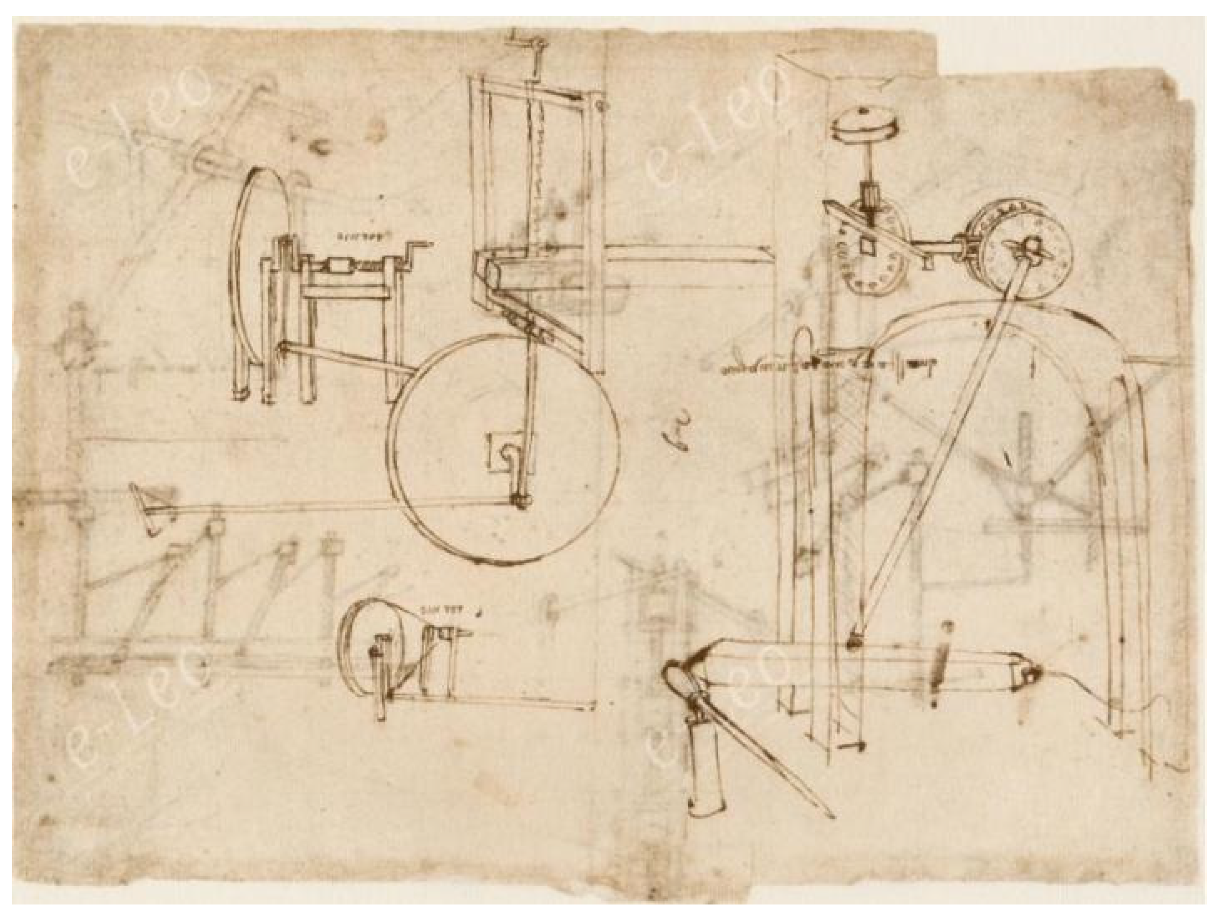
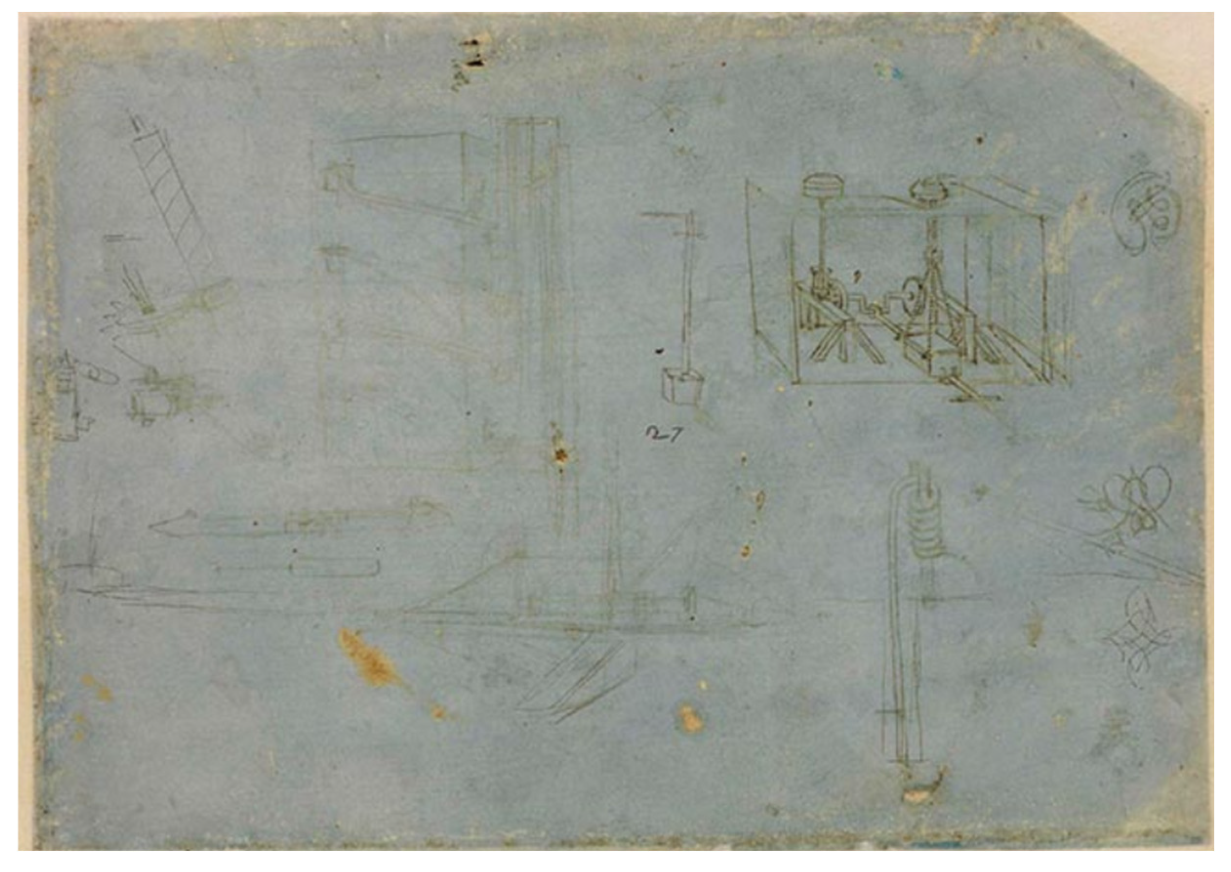
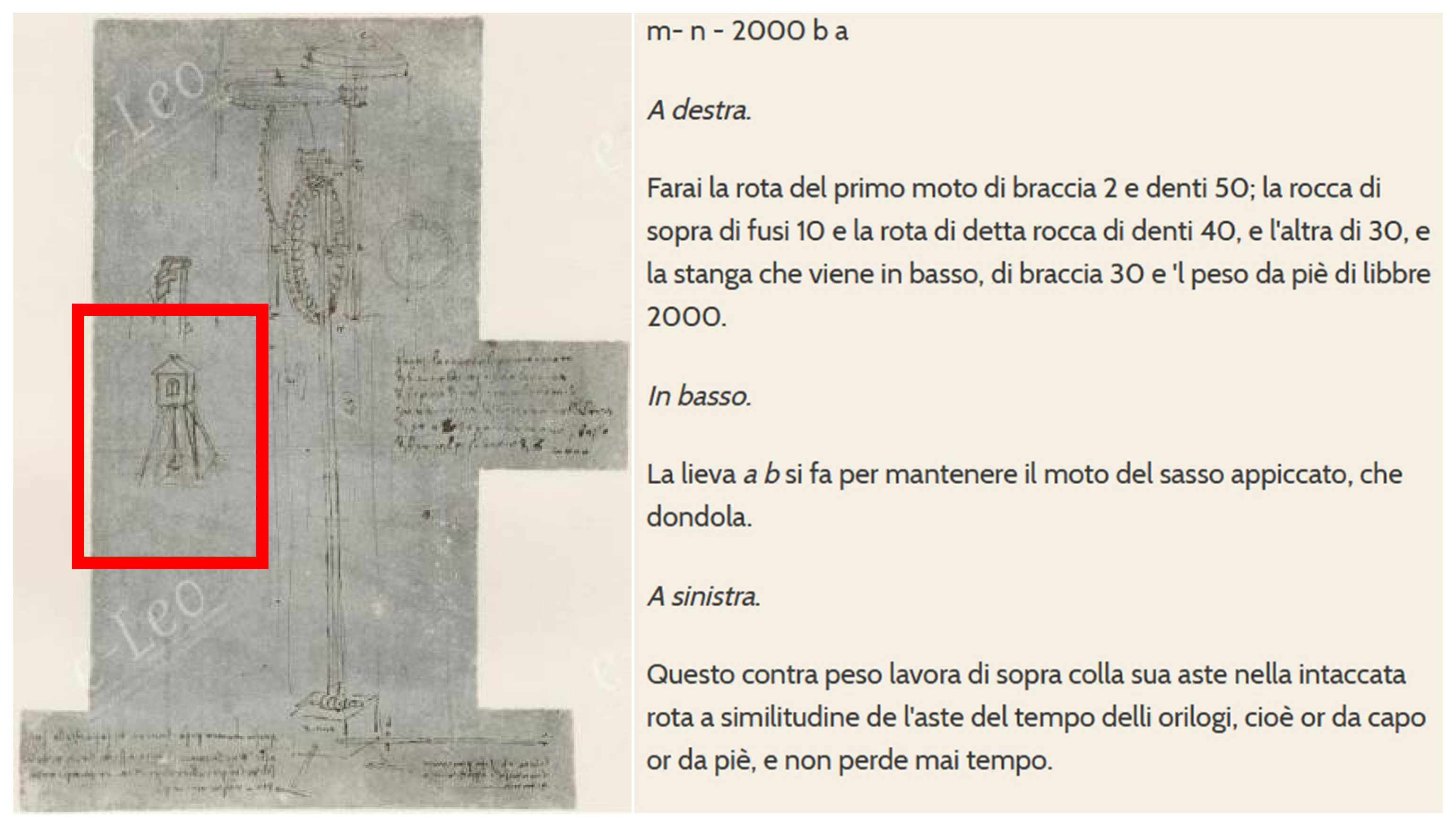
The second iteration of the Pendulum Mill appears on sheet 1065r of the Codex Atlanticus [13], dated to 1485 [11]. In this concept, there are notable similarities with the final design. In this sheet, Leonardo also hypothesizes a different design for the hosting structure, shifting from a masonry building (of the precedent concept) to a wooden stilt framework. The third concept appears on sheet 61v of Codex Madrid I [14], dated between 1493 and 1497 [12]. Here, Leonardo focuses more on the escapement mechanism rather than the pendulum itself.
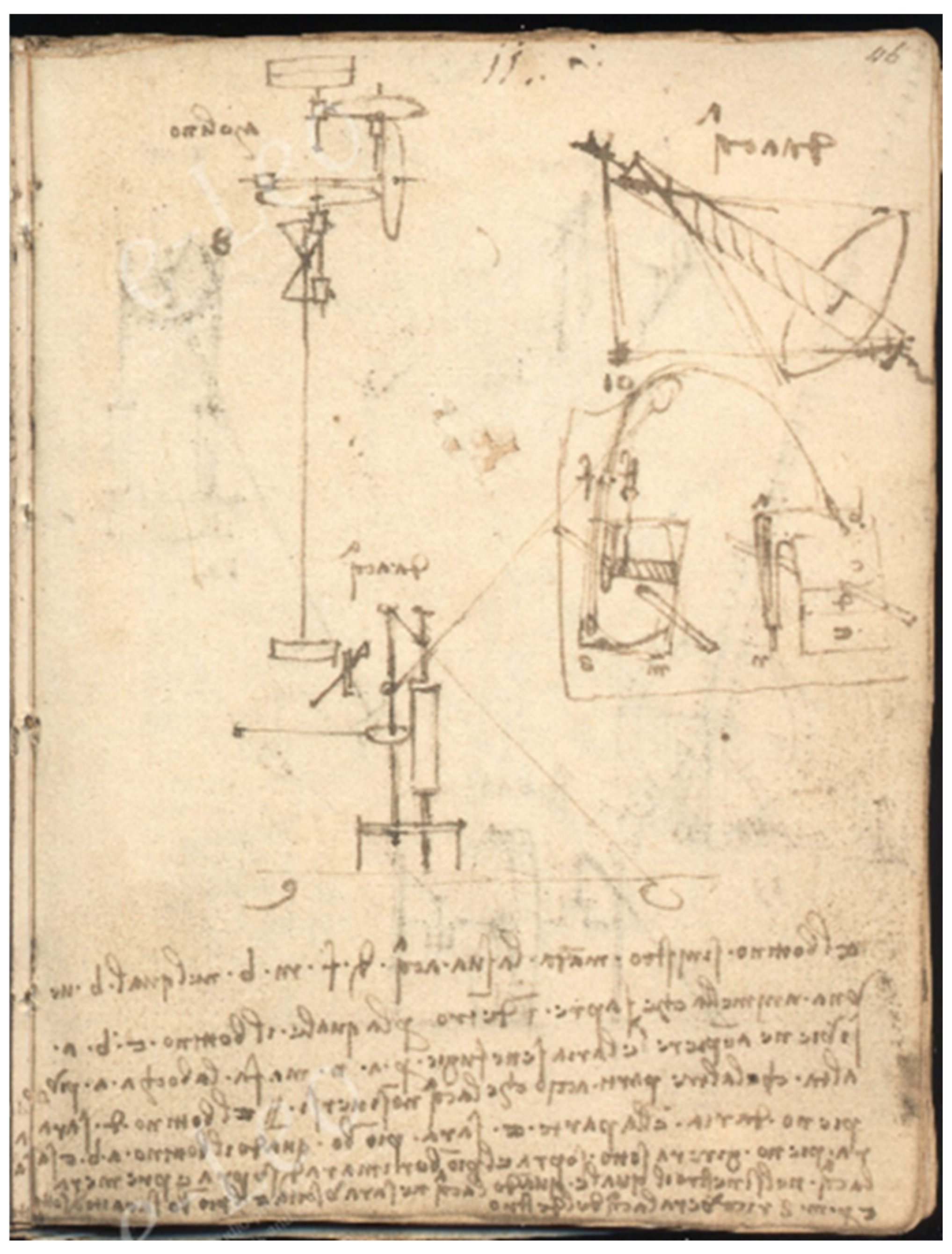
The fourth iteration of the mill is illustrated on sheet 46r of Codex Forster I [15], dated to 1505 [12]. This drawing diverges from earlier versions, showing significant similarities to the final design. Although the text provides limited information, the drawing features elements directly related to the final design, such as the hourglass shape with two spindles, and the lever mechanism near the oscillating mass.
Leonardo’s final known iteration of the Pendulum Mill appears on sheet 170r of the Codex Atlanticus [13]. By this time (around 1513). This last version of the mill will be deeply analyzed in the next section. Anyhow, it is possible to infer that Leonardo applies clockmaking principles for the development of the idea of Pendulum Mill. Indeed, he had an in-depth understanding of clock mechanisms, thanks to his studies about Brunelleschi’s designs, and his further studies on the topic during his time in Milan, as evidenced by his sketches of the Chiaravalle Abbey clock, such as Sheet 1111v of the Codex Atlanticus [16].
After the time around the realization of the last version of the Pendulum Mill, Leonardo had moved from Milan to Rome. In his later years, his focus shifted from mechanical inventions to art and anatomical studies. This could be a reasonable motivation of the absence of further developments of the idea.

3. Materials and Methods

3.1. The Sheet 170r of the Codex Atlanticus

Figure 2 reports a detailed view of the sheet that Leonardo entirely dedicated to the last concept of the pendulum mill. The most recent dating of the sheet, proposed by art historian Pietro C. Marani in 2004 [11], suggests that the drawing was created around 1513. Thanks to the work of historians and the e-leo platform [17], it is now possible not only to view Leonardo’s drawings but also to read the notes he left on the sheets.
The text reported in this sheet has been highlighted in Figure 2 and identified by letters. The English translation of each text group is then reported in Table 1.
The details provided in Table 1 are quite specific and precise, as the graphic representation of the machine (Figure 2). The device is a flour mill employing a traditional stone grinding system common in that era. However, unlike conventional mills powered by water, wind, animal, or human force, this mill uses a pendulum as its source of motion.
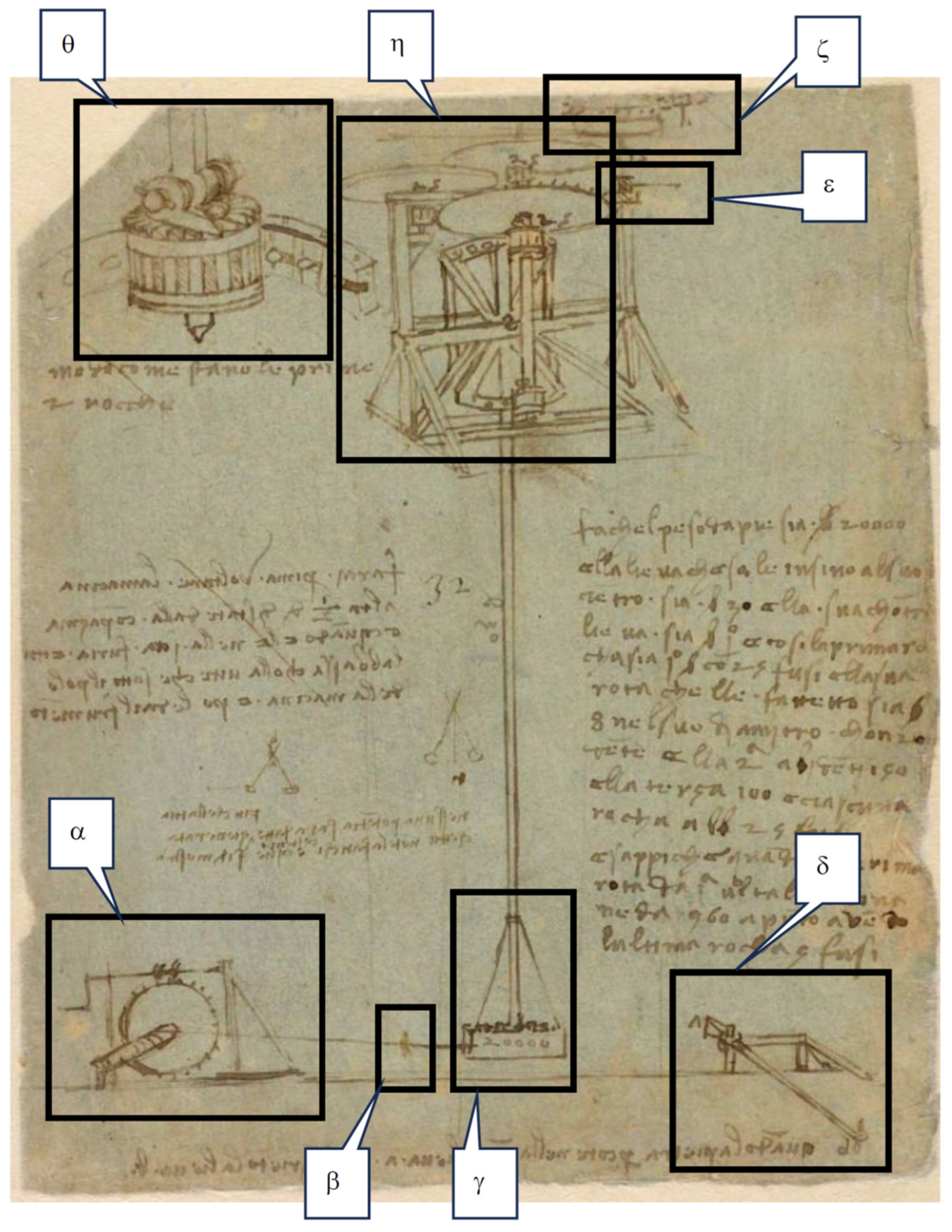
Figure 3 highlights the key details of the machines represented in the sheet, in order to support their description in the next paragraphs.
Referring to Row “a” of Table 1, the pendulum was expected to be 30 arms long (considered here based on the Renaissance unit used in Florence, approximately 0.583 m [18]), with a suspended mass of 20,000 pounds (using the Renaissance Florentine standard, approximately 0.3395 kg [18]). Converted to modern units, the pendulum’s length is approximately 17.49 m, and the oscillating mass weighs 6790 kg. Therefore, this mechanism was intended to be implemented in a massive structure, capable of hosting the long oscillating rod. A possible hint about the hosting structure, can be found in Sheet 1065r of the Codex Atlanticus.
Now referring to Figure 3, in the lower-left corner there is a winch (Detail α) with a manual crank and a drum around which a rope is wound, connected to the pendulum’s suspended mass. On the opposite side, in the lower right, there is something that resembles a lever with a robust pedestal (Detail δ in Figure 3). Accordingly, Leonardo refers to it as the lever and counter-lever (row “b” in Table 1). From the suspended mass (Detail γ in Figure 3), assisted by what appears to be ropes, the pendulum rod rises upward, terminating in the group of wheels and spindles (Detail η in Figure 3).
More in particular, the pendulum rod is directly connected to an hourglass-shaped wheel, which is connected to two spindles on the same vertical axis. The hourglass-shaped wheel, which is observable also in the precedent sketch of the pendulum mill made by Leonardo (see Figure 1, the sheet 46r of Codex Forster I), is a key element for the concept. Indeed, it allows to exploit the motion of the pendulum in both directions, while producing the rotation of the mill in only one direction. Indeed, the two spindles represented in Detail η of Figure 3 are not simple ones, since they are equipped with a particular and unique escapement mechanism, as represented in Detail θ of Figure 3. This escapement system, which substantially differs from the others commonly used by Leonardo in other machines [2], allows the spindle to transmit the torque in only one direction. Hereinafter, the spindles equipped with escapement will be called “escapement spindles”.
Therefore, the two escapement spindles work alternately, i.e., when one of them is transmitting the torque from the hourglass-shaped wheel, the other is not, and vice versa. The motion is then transmitted to the upper group of wheels and spindles by means of a vertical axis, thought by Leonardo to multiply the rotation speed. No details are provided about the vertical shaft on which the spindles are mounted. However, it is an important detail for the functioning of the machine.
Interpreting what reported by Leonardo in Row “a” of Table 2, the hourglass-shaped wheel (first wheel) has a radius of one arm. In fact, Leonardo refers to a lever of 30 arms (the rod) and a counter-lever of one arm. According to Detail η in Figure 3, it is quite intuitive to observe that is the position of the teeth of the hourglass-shaped wheel which determines the counter-lever.
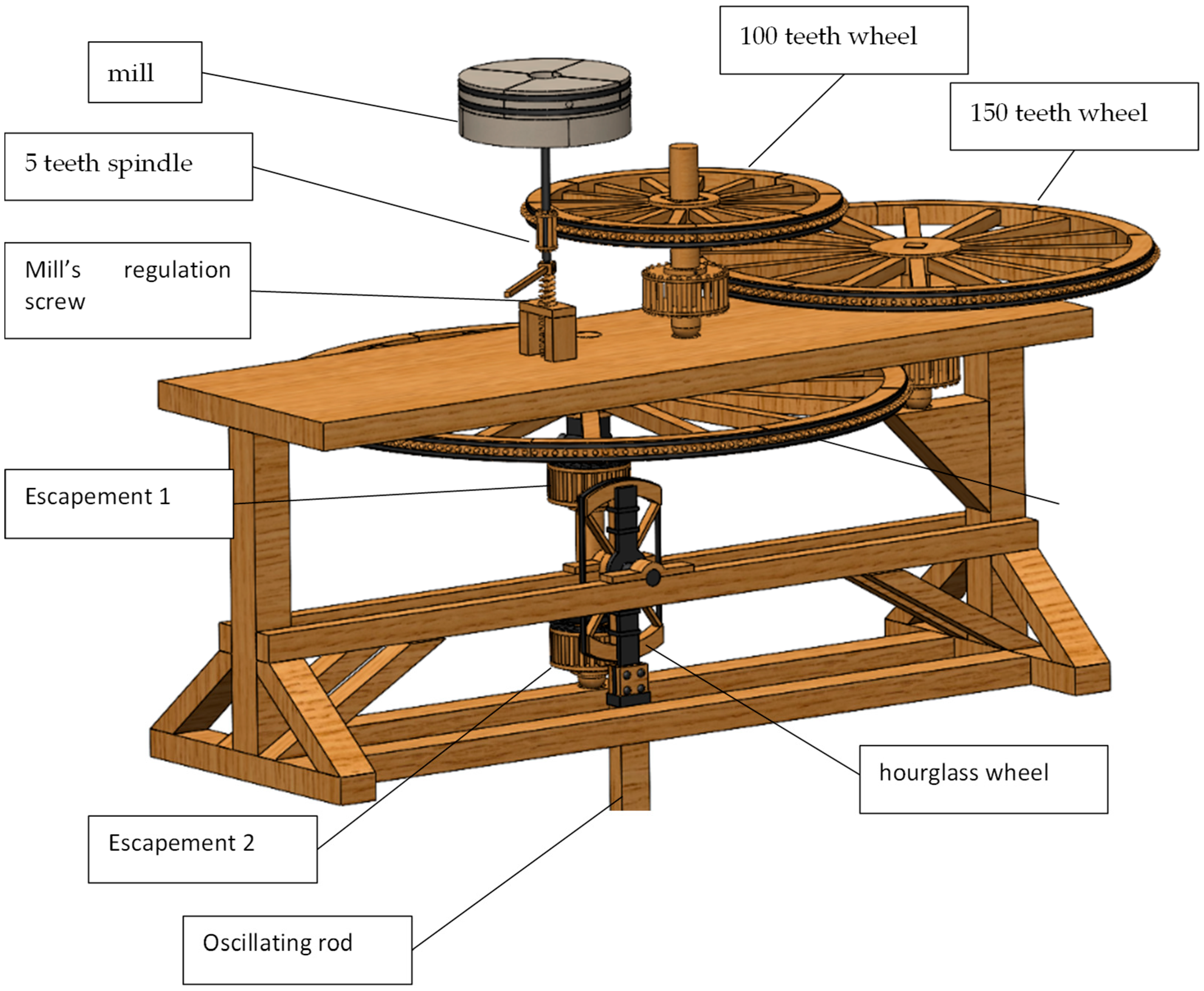
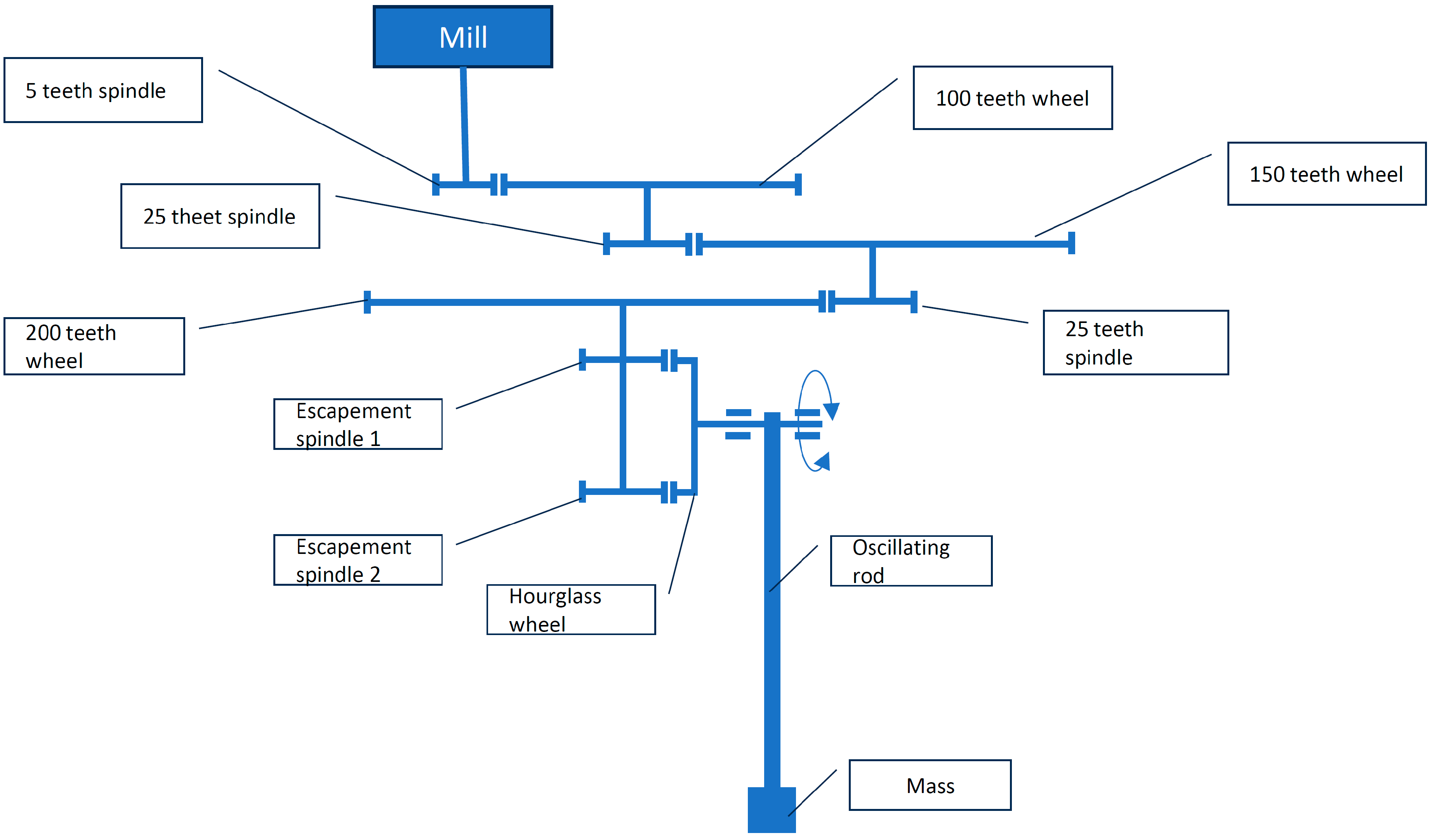
The first circular wheel mentioned by Leonardo in Row “a” of Table 2, is that mounted on the top of the vertical shaft connected to the two escapement spindles (which of them equipped with 25 teeth). Such a wheel is equipped with 200 pins, and matches with another spindle with 25 teeth, rigidly and coaxially connected to a second wheel with 150 pins. Similarly, the last wheel meshes with another spindle with 25 teeth, on which, in turn, the third wheel (with 100 pins) is rigidly and coaxially connected. The latter, meshes with a last spindle, equipped with 5 teeth. Consequently, Leonardo states that the transmission ratio of this gear train is 960 (one revolution of the first wheel results in 960 revolutions of the millstone).
Detail ε in Figure 3 represents a regulation screw mentioned in Row “d” of Table 2. It is intended to be used for regulating the vertical gap between the static stone and the rotating stone of the mill. The lower is the gap, the finer is the produced flour.
Detail ζ in Figure 3 substantially represents the mill, intended as a conventional one for the period, except for a series of radial pins installed on it. Additionally, it is possible to observe something that resembles an additional spindle, near to the rotating part of the mill. Maybe, Leonardo intended to give an additional functionality to the mill, i.e., transmitting torque to a spindle linked to some mechanical device (e.g., a vibrating device for conveying the flour to its final destination). However, nothing has been found in the documents, which could help in giving a robust interpretation to this detail.
The last key element to be observed in Figure 3 is Detail β in Figure 3. The drawing is not very clear, but due to the position (i.e., in the middle of the rope that allows the winch to set the mass in its starting position), it is probably a re-usable disconnecting device, like those used for catapults (e.g., Sheet 141r in the Codex Atlanticus).

3.2. Approach for the Study and Reconstruction of Leonardo da Vinci’s Pendulum Mill

The reconstruction of Leonardo da Vinci’s pendulum-driven mill requires a rigorous and interdisciplinary methodology that integrates historical research with engineering analysis. Given the fragmentary nature of the available documentation and the inherent ambiguities in Leonardo’s manuscripts, the approach adopted in this study can be resumed according to the following steps:
1.
Systematic analysis of historical sources;
2.
Interpretative comparison with other known machines from Leonardo and his contemporaries;
3.
Formulation of a coherent digital reconstruction that adheres to both historical and mechanical plausibility.
Here in the following, they will be deeply described.

3.2.1. Historical Source Analysis

The first phase of the study involves a thorough examination of all extant documentation related to the proposed machine. This is primarily based on research conducted within official repositories of Leonardo’s works, such as the Codex Atlanticus, as well as previous studies that have attempted to catalog and interpret his technical drawings. The analysis is not limited to a direct reading of the specific sheets referencing the pendulum mill but extends to a broader contextualization of Leonardo’s work within the corpus of Renaissance engineering. Special attention is given to the handwritten notes accompanying the sketches (made readable by the platform Eleo [17]), as these often provide critical insights into Leonardo’s design rationale, albeit sometimes in an elliptical or abbreviated form.
As shown in Section 2, most of information provided by Leonardo about the pendulum mill is given in the sheet 170r of the Codex Atlanticus. Nevertheless, a lot of details needed for high-fidelity reconstructions are not sufficiently described and/or represented, or even not mentioned at all.
Therefore, to fill this gap, historical cross-referencing is conducted with other technological developments of the period, drawing from treatises by contemporaneous engineers such as Taccola, Francesco di Giorgio, and Valturio [7,8]. This comparative framework helps to position Leonardo’s design within the broader landscape of late 15th- and early 16th-century mechanical engineering and allows for a more informed interpretation of ambiguous or missing details.

3.2.2. Interpretative Reconstruction of the Concept

Once the available documentation has been scrutinized, the study proceeds with an interpretative phase aimed at filling gaps and resolving inconsistencies in the original material. As mentioned before in this paper, Leonardo’s drawings are not always exhaustive in their depiction of mechanical components, requiring an inferential reasoning to complete the design. In facing these issue, the methodology follows a hierarchical approach:
  • Direct Reference to Leonardo’s other works. If a specific mechanism or structural element is not explicitly represented in the sheet under study but can be identified in Leonardo’s other designs with a high degree of certainty, it is incorporated into the reconstruction. This ensures that the inferred components remain consistent with Leonardo’s established design principles and knowledge.
  • Comparison with Analogous Machines from Leonardo’s Era. In cases where no clear precedent exists within Leonardo’s own works, reference is made to similar contemporary machines. Given that Renaissance engineering often exhibited a degree of standardization in mechanical solutions, especially in the domains of milling, gearing, and power transmission, this comparative approach provides a historically reliable knowledge basis for reconstructing missing elements.
  • Functional and Structural Plausibility Assessment. Where neither of the above strategies yields a definitive answer, the study resorts to a mechanical feasibility analysis informed by established principles of Renaissance engineering. This involves assessing whether a proposed reconstruction would have been manufacturable by using the materials and techniques available in Leonardo’s time, as well as whether it aligns with known principles of mechanical advantage, friction management, and structural integrity.
An essential aspect of this interpretative phase is the multidisciplinary collaboration between historians and engineers. While historians provide expertise in deciphering Leonardo’s notation, contextualizing the drawings, and identifying historical precedents, engineers contribute to a quantitative and functional perspective, ensuring that the reconstructed mechanisms are not only historically credible but also mechanically viable. The integration of these perspectives is crucial for distinguishing between purely speculative interpretations and those grounded in technical realism.
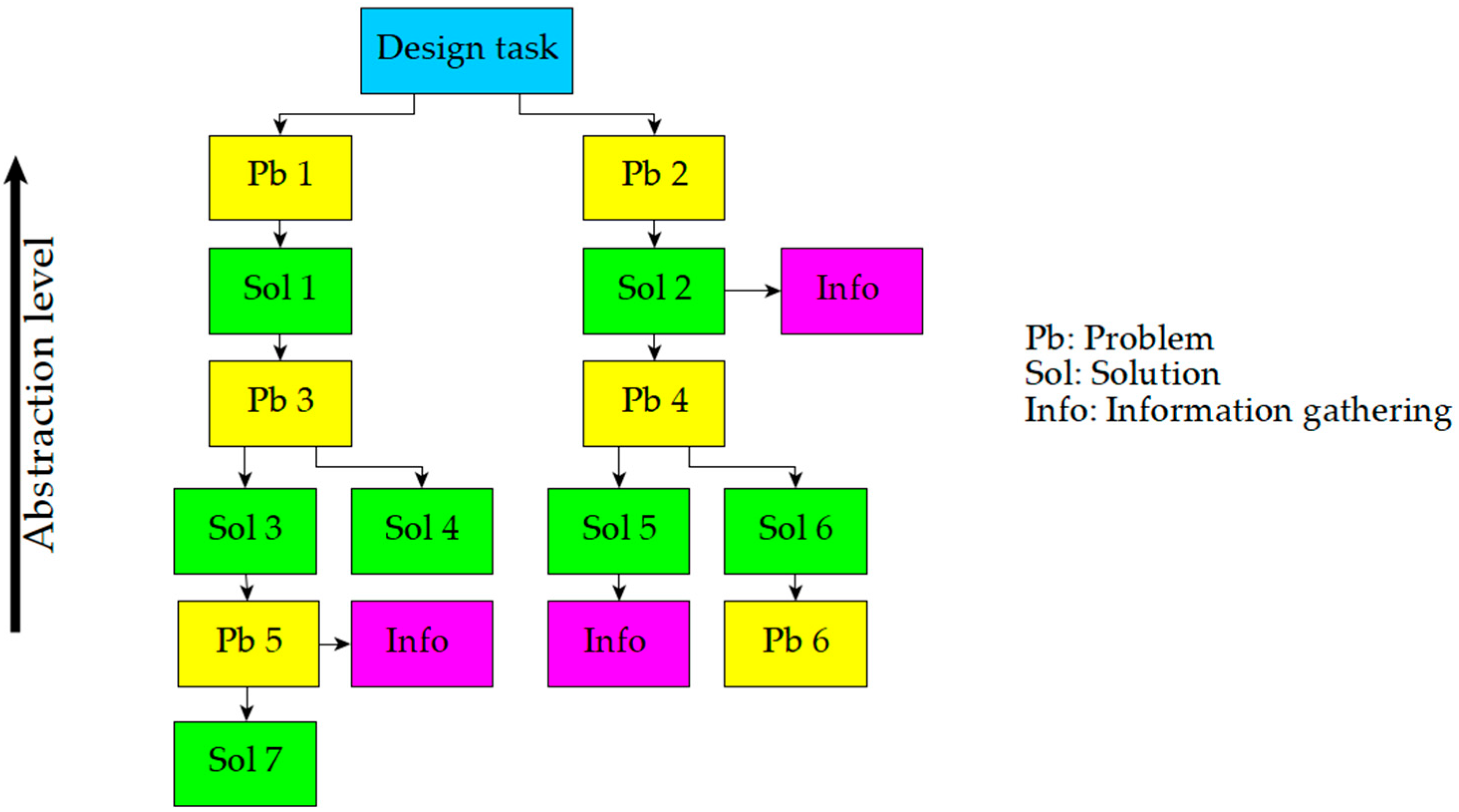
To facilitate this process, the Problem Solution Network (PSN) [19,20] was employed as the methodological framework for managing the interdisciplinary processes between historians and engineers. The PSN framework (Figure 4) was originally developed to support the conceptualization of complex technical systems by structuring the decision-making process in engineering design. This same methodology has been adapted for historical machine reconstruction, where uncertainties in source material require a rigorous, traceable approach to hypothesis formulation and validation [9].
A key component of the PSN’s implementation in this context is its integration with the Function-Behavior-Structure (FBS) framework, as proposed by Gero [21,22,23]. The FBS model provides a structured way to describe and analyze technical systems by distinguishing between three levels of representation:
  • Function (F): The intended purpose of the machine, as inferred from historical sources and comparative analysis. In this case, the function is the transformation of pendular motion into continuous rotational motion for milling.
  • Behavior (B): The operational principles that enable the function to be realized, such as the oscillatory motion of the pendulum, its interaction with the transmission system, and the resulting torque applied to the millstone.
  • Structure (S): The physical components that constitute the system, including gears, levers, axles, and the pendulum mechanism itself.
By mapping Leonardo’s conceptual sketches onto the PSN framework, the study ensures that each design element is examined not only in terms of its geometric and mechanical properties but also in relation to the intended functional problems resolved by exploiting specific behaviors or structural solutions (see Figure 5).
This structured approach helps to resolve ambiguities in the historical documentation by systematically evaluating possible alternative reconstructions within the constraints of Renaissance technology. Indeed, the application of PSN to historical machine reconstruction has been further refined in recent studies, where the methodology has been employed to reconstruct the Glider of Leonardo da Vinci [9].
By integrating PSN with digital modeling techniques, the study can maintain a clear distinction between confirmed historical evidence and inferred design elements, ensuring that all assumptions are explicitly documented and subject to iterative validation.
To enhance the applicability of the PSN framework in this study, a digital adaptation was implemented by integrating hyperlinked content and a structured cloud-based repository. Specifically, key nodes within the PSN (those identified as crucial for the interpretation of Leonardo’s pendulum-driven mill) were linked to supporting documents containing relevant references, visual representations, bibliographic sources, and hyperlinks to online resources. This approach transformed the traditional PSN into an interactive knowledge platform, enabling a more dynamic exchange of information among the multidisciplinary team.
A dedicated Google Drive repository was established to host the supporting materials, with each file corresponding to a specific conceptual or structural element within the PSN. This repository contained:
  • Annotated sketches derived from Leonardo’s original sheets, with overlays highlighting key mechanical components and hypothesized interactions.
  • Comparative analyses referencing similar Renaissance-era machines, aiding in the interpretation of ambiguous design elements.
  • Technical literature and historical sources, organized by thematic relevance to facilitate targeted access to background information.
  • External resources, including hyperlinks to digitized manuscripts and engineering databases for additional verification.
Through this system, each key concept within the PSN was not merely an abstract node but a gateway to deeper layers of structured knowledge, ensuring that every interpretation or hypothesis was substantiated by tangible evidence. Team members could seamlessly navigate from a specific problem statement (e.g., the function of a particular gear in the transmission system) to a curated set of resources supporting its analysis.
This interactive adaptation of the PSN framework proved particularly effective in fostering real-time collaboration between historians and engineers. By providing a centralized, accessible repository, the methodology encouraged iterative refinement of hypotheses, allowing experts from different disciplines to contribute insights, challenge assumptions, and collectively refine the conceptual model of the pendulum-driven mill. The integration of hyperlinked content not only streamlined the decision-making process but also facilitated traceability, ensuring that every interpretative choice was grounded in documented sources.
Ultimately, the adoption of this structured methodological framework ensures that the reconstructed model is not only visually representative of Leonardo’s sketches but also functionally coherent, providing a valuable basis for further analysis of its potential operational viability.

3.2.3. Digital Reconstruction of the Pendulum Mill

The development of the Computer Aided Design (CAD) model followed a systematic design approach, grounded in the conceptual framework established through the PSN. The initial phase of modeling was deeply informed by the interpretative work carried out in the documentation analysis stage, where the PSN served as a fundamental tool for structuring hypotheses, correlating historical sources, and facilitating interdisciplinary collaboration.
Once a sufficiently robust conceptual understanding of the pendulum-driven mill was achieved, the modeling process was initiated through freehand sketches of the core functional macro-blocks (e.g., the winch mechanism, the transmission system, the oscillating mass, etc.). These preliminary drawings were essential in visualizing possible reconstructions and were subjected to critical review by both engineers and historians. This step allowed for the early identification of inconsistencies, historical anachronisms, or mechanical implausibility, ensuring that only the most technically and historically coherent interpretations were carried forward.
Following this phase of concept validation, the process transitioned into an embodiment design stage [24] using parametric CAD modeling. At this point, more precise definitions of geometries and proportions were introduced. The modeling was not merely an exercise in visualization but an analytical tool for evaluating mechanical feasibility. Several factors were taken into account to refine the CAD representation:
  • Proportional calculations based on Leonardo’s original annotations, integrating unit conversions where necessary (e.g., the translation of Renaissance measurement systems into modern SI units).
  • Human factor considerations, estimating dimensions according to the average stature and biomechanics of period laborers, ensuring that operational aspects of the machine were realistically scaled.
  • Dynamic constraints, particularly in relation to the physics of the pendulum, verifying whether the hypothesized motion transmission system could feasibly generate the required torque and rotational speeds.
Given the inherent uncertainties in reconstructing an incomplete design, the CAD modeling process was inherently iterative, incorporating continuous refinements based on historical feedback, mechanical validation, and interdisciplinary discussions. The flexibility of digital modeling tools allowed for rapid adjustments in response to emerging insights, bridging the gap between historical fidelity and mechanical plausibility.
Ultimately, this structured yet adaptive approach ensured that the final CAD model was not only a visualization of Leonardo’s concept but also a functional representation, enabling discussions on its potential operability and integration within the technological landscape of the time.

4. Results

4.1. The PSN

In this subsection, the results derived from the application of the PSN framework to the reconstruction of Leonardo da Vinci’s Pendulum Mill are presented.
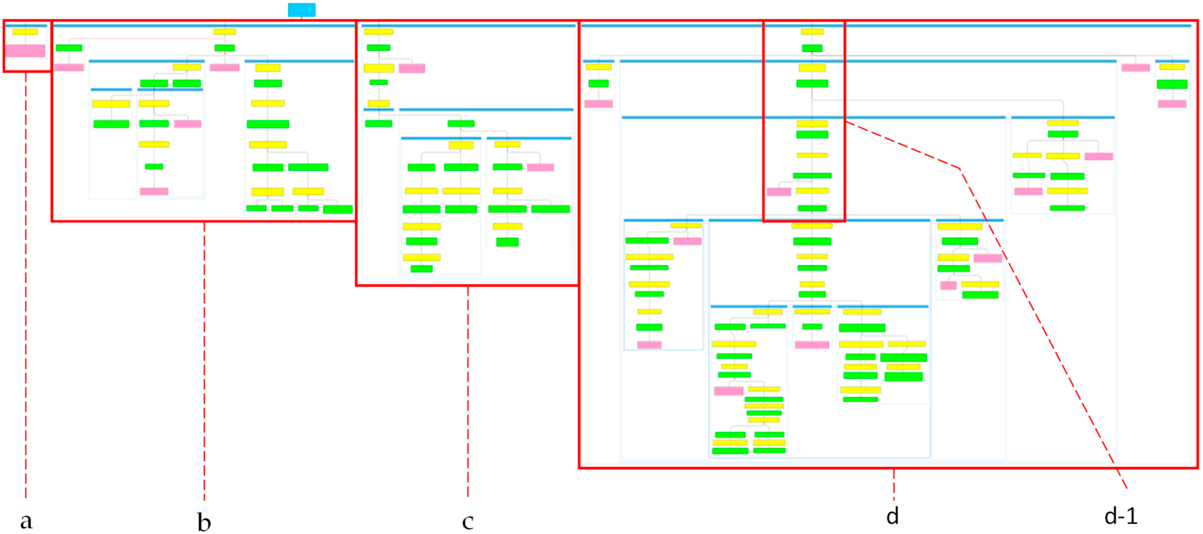
Figure 6 presents an overview of the network’s overall structure, showcasing the extent of the problem-solving framework without delving into the specific content of the individual nodes. From this high-level perspective, it is possible to identify the four main branches that correspond to the four key functions of the Pendulum Mill. These branches represent the primary areas of focus within the reconstruction process, each linked to one of the core functions necessary for the mill’s operation. The aim of Figure 6 is not to examine the individual details but to provide a broad view of the network’s scope, illustrating how the different functions are interconnected within the overall problem-solving framework.
In the following section, a more detailed description of the “d” branch (see Table 2) is provided, highlighting the most relevant nodes that illustrate how the network facilitates the interaction between engineers and historians.
Indeed, we intend to show how the PSN is structured in the context of the project without delving into all the details of the whole network. In fact, it is important to note that some branches and nodes are still in the process of development. The unveiled branches concern specific details related to sub-parts of the machine, which are needed for high-fidelity physical reconstruction, and then fall out from the scope of this work. Therefore, the analysis presented here will focus on the more mature nodes and branches, offering a representative view of the overall process.
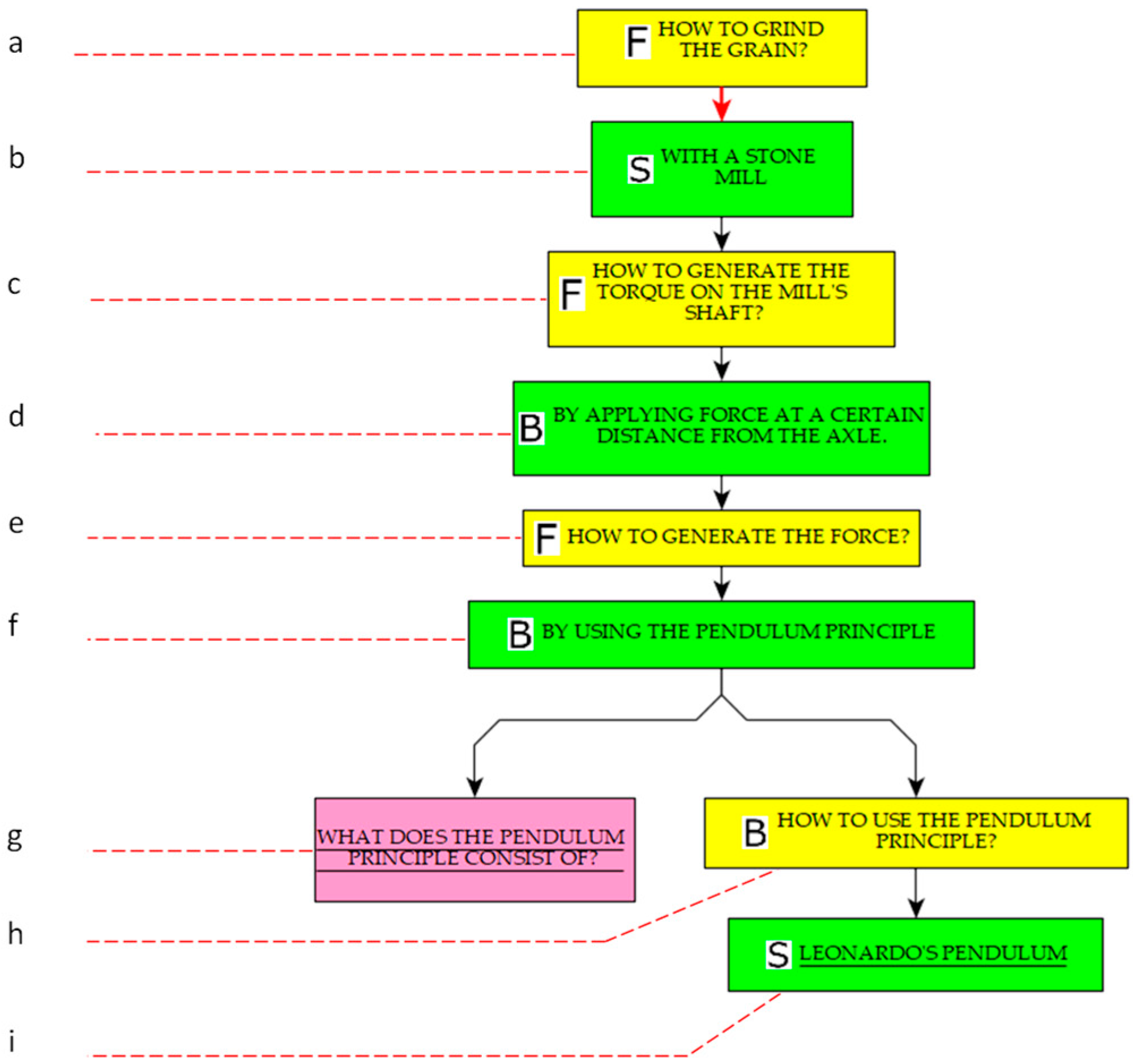
In particular, Figure 7 shows a magnified version of the set of boxes “d-1” previously highlighted in Figure 6. This sequence of problems and solutions (and one information box) forms the starting set of PSN boxes for the branch “d” in Table 2.
A description of the specific boxes shown in Figure 7 is reported in Table 3.

4.2. Key Element: The Gear Train

The reconstruction of Leonardo’s pendulum-driven mill aims to reproduce his conceptual vision rather than create a functional mechanism. The work interprets the structural and kinematic relationships between components in line with Leonardo’s design principles while recognizing the ambiguities of the original sources. Given the many missing or incomplete details in the manuscripts, the model represents a preliminary visualization of Leonardo’s idea, not a finalized design intended for physical realization.
The most critical element of the system is the pin-wheel gear train, which appears to function as the primary transmission mechanism. Leonardo frequently employed pin-based gears in his other mechanical studies, often as an alternative to traditional involute gear teeth. In this reconstruction, the large primary wheel features an array of radially arranged pins, engaging with secondary rotating elements (spindles) to propagate movement across multiple stages. The dimension of both wheels and spindles has been obtained by strictly considering the indications given by Leonardo (see Table 2), and by performing preliminary multibody simulations. In this way, it has been possible to obtain the overall geartrain, as shown in Figure 8. A schematic representation of the gear train is reported in Appendix B.
One of the most distinctive features of the reconstructed system is the hourglass-shaped wheel and the related escapement mechanism, which plays a fundamental role in regulating the interaction between the pendulum and the gear train. As visible in Figure 8, the dimensions obtained for the hourglass wheel are not compatible with the proportions shown in Figure 1. Indeed, as reported in Table 2, Row “a”, Leonardo provided a precise indication about the ratio between the length of the pendulum and its counter lever (i.e., the radius of the hourglass wheel). In this work, it has been preferred to follow the explicit textual indications (when present), instead of fixating on the graphic proportions provided in the sketches.
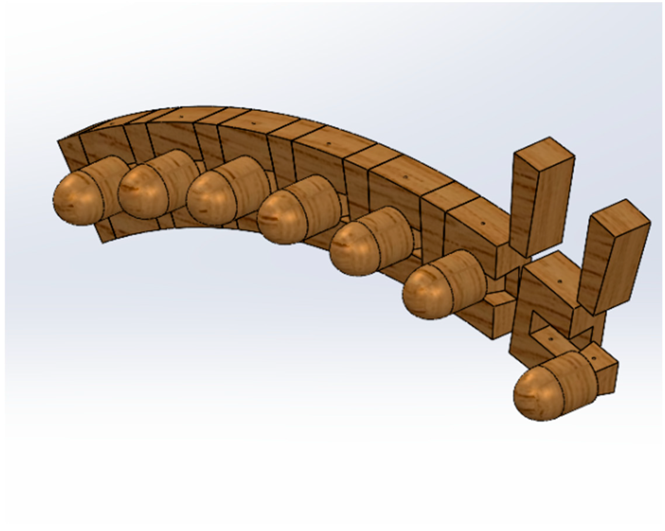
Unlike traditional escapements that rely on rigid, evenly spaced interactions, according to Sheet 170r of the Codex Atlanticus, Leonardo’s hourglass escapement includes removable pins (Figure 9), allowing periodic substitution, when these element become worn. However, details about the actual constructive form of the whole hourglass-shaped wheel are not available.
The alternating nature of the engagements between the hourglass wheel and the escapements implies that the pendulum’s oscillatory motion may have been converted into an intermittent drive for the rest of the mechanism. The exact purpose of the removable pegs remains speculative, but their inclusion in the reconstruction provides a means of exploring how Leonardo may have sought to consider maintenance issues.
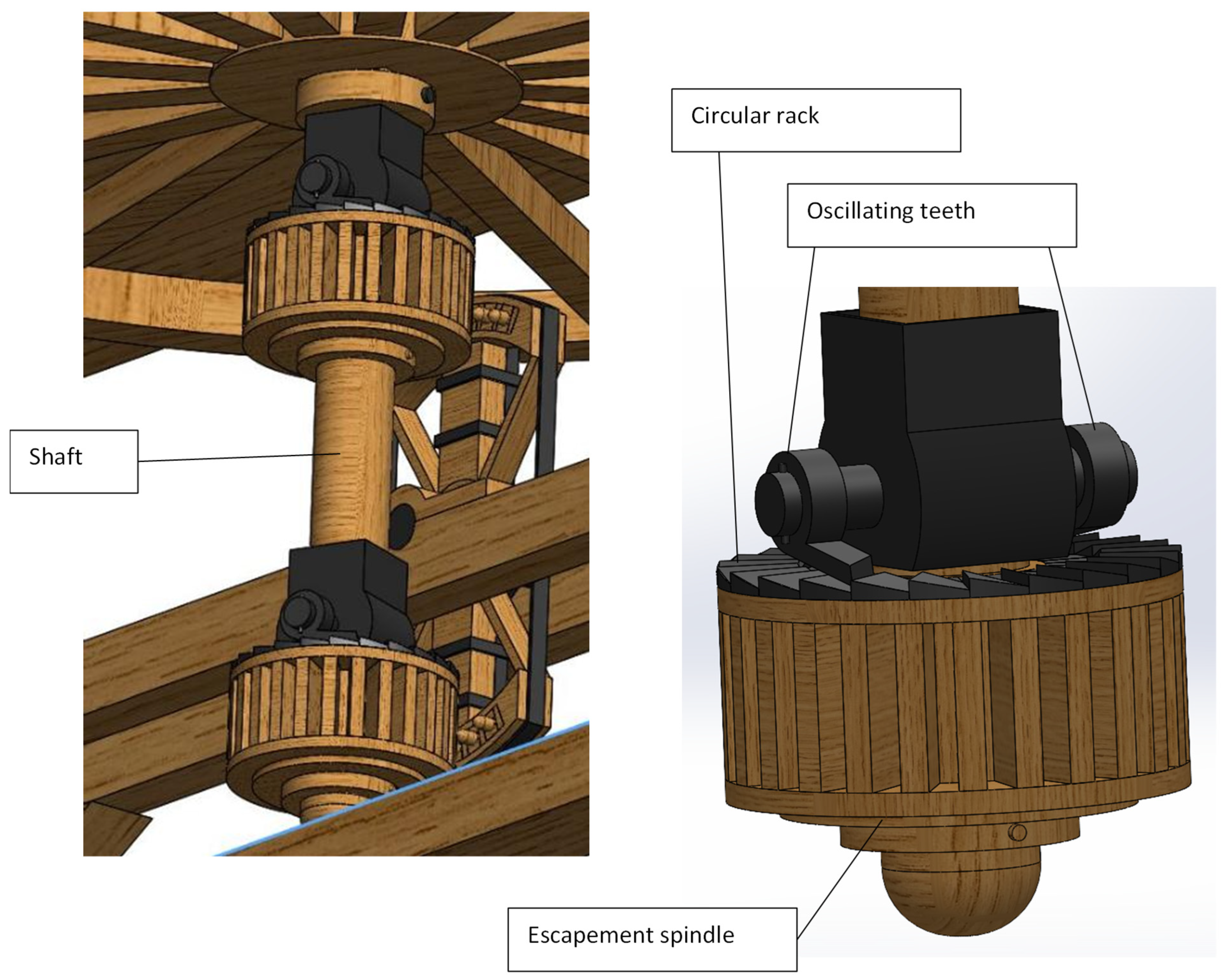
Closely related to the escapement mechanism is the double-rotation axle (Figure 10), which appears to alternate its engagement between two separate gear stages. The presence of two independent pinions suggests that Leonardo was exploring ways to convert the bidirectional movement of the pendulum into a more continuous rotational output. This is particularly significant in the context of milling applications, where an uninterrupted rotary motion would have been necessary for effective grinding. The reconstructed model presents this double-rotation axle as a means of allowing the system to function with alternating impulses while maintaining an overall directional consistency in the driven elements. More specifically, the system operates due to the fact that the spindles are mounted idly on the shaft, which engages with them coaxially through a circular rack system. The circular rack is securely attached to the spindles, while the movable teeth (two for each spindle) are fixed to the shaft (see Figure 10). Circular racks and movable teeth are mounted to allow the spindles to freely rotate in one sense, while in the other sense of rotation transmit torque to the shaft. In this way, the oscillating movements of the hourglass-shaped wheel is transformed in a rotation of the shaft (periodically ranging from zero to the maximum speed), in a single rotational direction.
Unfortunately, due to the absence of data about the actual friction, as well as the mechanical performance of the gear train, it is impossible to estimate the value of the rotational speed. Certainly, Leonardo believed that the movements of the pendulum would be very slow, due to the high speed multiplication ratio (960) he considered.
The pendulum itself is another key component, defined primarily by the proportions provided in Leonardo’s notes. According to the textual indications, the pendulum is 30 arms (~17.49 m) in length and has a suspended mass of 20,000 pounds (~6790 kg). While these dimensions have been faithfully incorporated into the model, the practical implications of such a large-scale pendulum remain uncertain. Given that Leonardo’s designs often involved theoretical explorations rather than immediately realizable mechanisms, it is possible that the proportions were intended more as conceptual guidelines than as precise engineering specifications. The pendulum is depicted as being suspended from a fixed support structure, with its lower mass interacting directly with the hourglass escapement mechanism. The precise method of attachment and suspension remains open to interpretation, but the reconstruction follows the most mechanically coherent arrangement based on available references.

4.3. Digital Model of the Whole Milling Structure

The final CAD representation integrates all the elements into a single visualization, illustrating the spatial organization and mechanical relationships between components (see Figure 11 and Figure 12). The reconstructed system is presented as a series of interconnected functional blocks, with each key element positioned according to Leonardo’s descriptions and the inferred logic of the design. The gear train, escapement mechanism, and pendulum are all depicted in relative proportion to one another, allowing for an overall assessment of how Leonardo may have envisioned their interaction.
It is important to emphasize that this reconstruction remains at a preliminary stage, lacking many of the fine details that would be necessary for an actual physical high-fidelity reconstruction (maybe in a opportunely reduced scale). While the broad mechanical layout follows a logical interpretation of Leonardo’s sketches, aspects such as material properties, structural reinforcements, and precise machining tolerances have not been addressed. These refinements would be required for any attempt at physical realization, whether through digital simulations or scaled physical models. Furthermore, the current model does not account for wear, friction, or dynamic stability, as its purpose is to visualize Leonardo’s conceptual design rather than to validate its mechanical feasibility.
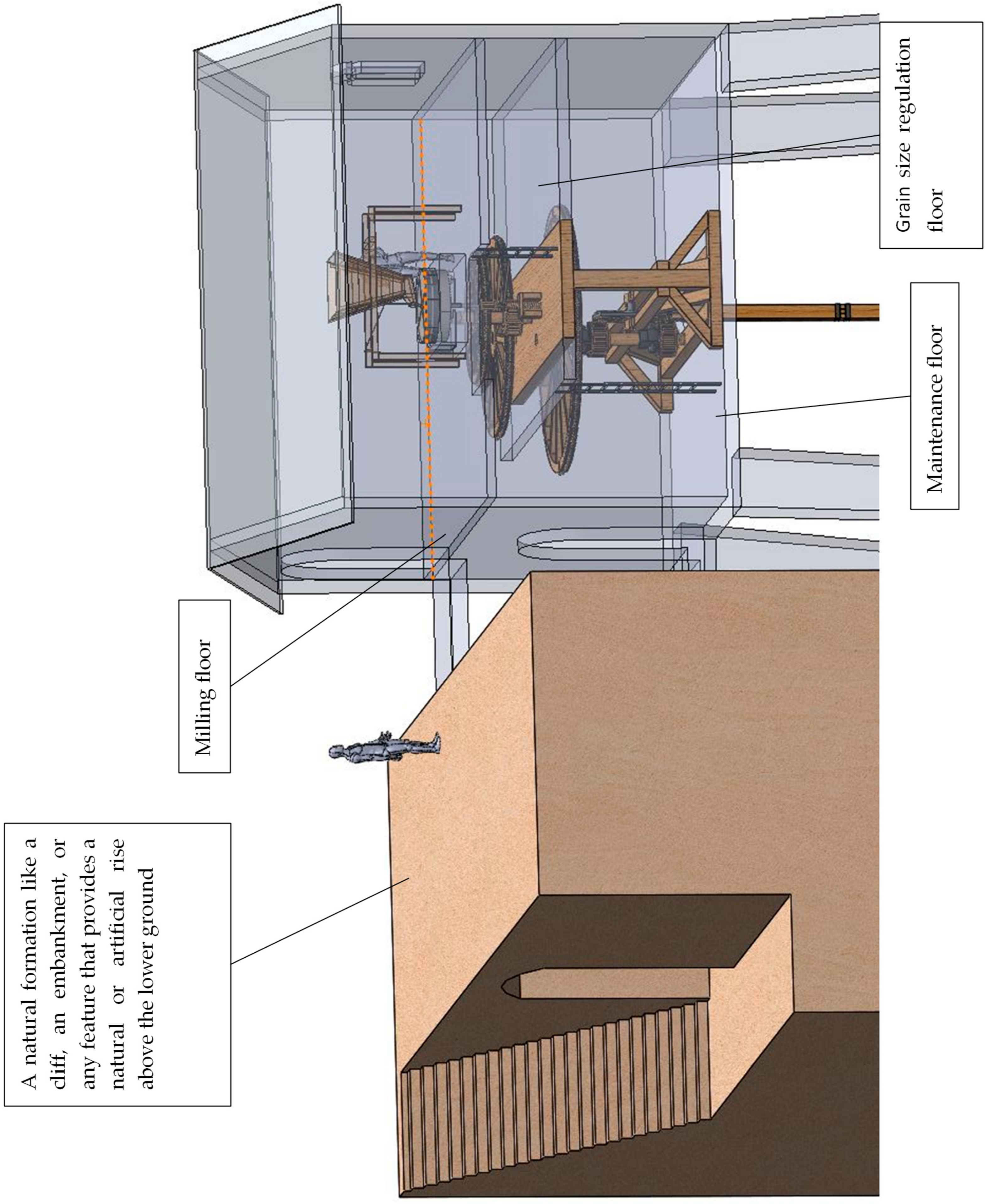
By observing Figure 9, it is possible to note that the mechanism has been integrated into a hosting structure, which is inspired to that sketched by Leonardo in the Sheet 1065r of the Codex Atlanticus. The closed part of the mentioned structured has been divided into three floors (see Figure 12):
  • the “milling floor”, where the raw material is delivered and processed by the mill
  • the “grain size regulation floor”, where the regulating screw is placed. The regulating screw is intended to increase or decrease the gap between the two milling stones.
  • The “maintenance floor”, where there is full accessibility to the main mechanisms.
The three floors have been created by considering the big size of the mechanisms, as well as the need to keep the milling zone away from the natural grease probably used to lubricate the rotating parts.
In Figure 9, four different operators are shown (from Op.1 to Op.4), which implement the key functions needed to operate the plant:
  • Op.1 is the winch operator, which pulls the pendulum mass at his starting point.
  • Op.2 is the “hammer” operator. Indeed, by taking inspiration from Sheet 141r of the Codex Atlanticus, a disengaging mechanism has been devised, which uses the impact of an hammer to release the mass.
  • Op.3 is the “recharger” operator, which periodically uses the lever to give additional acceleration to the mass, in order to ensure a prolongated functioning of the milling plant.
  • Op.4 is the “milling operator”, which actually controls the hopper (surely present in a milling plant), the mill and its regulation.
Actually, due to the sequential nature of the operations exploited by Op.1, Op.2 and Op.3, it is possible to assert that even a single person can operate at the lower ground. Therefore, except for possible assistants, two persons can governate the pendulum mill of Leonardo da Vinci.

5. Discussions

This section provides a critical evaluation of the results obtained in light of the initial research objectives, explores the limitations inherent to the methodological and interpretative processes, and assesses the broader impact of the study within both academic discourse and societal engagement with historical engineering heritage. The discussion is structured to reflect the iterative and interdisciplinary nature of the research, emphasizing the methodological challenges and the potential for further refinements in the digital and physical reconstruction of Leonardo da Vinci’s pendulum-driven mill.

5.1. Evaluation of Results Against Initial Objectives

The primary objective of this research has been the conceptual reconstruction of Leonardo da Vinci’s pendulum-driven milling apparatus, with a focus on understanding and visualizing its structural logic, rather than verifying its practical operability. In light of this, the results achieved align coherently with the methodological framework initially established, enabling the articulation of a system-level interpretation that remains as faithful as possible to Leonardo’s design language and epistemological approach.
A central aim of the study was to clarify the interrelations between the primary components represented in the original sketches, and to extrapolate missing information through reasoned analogies with other codices and known technological solutions from Leonardo’s corpus and the broader context of late fifteenth- and early sixteenth-century mechanical design. The reconstruction of key elements such as the pin-wheel transmission, the hourglass-shaped escapement, the double-rotation axle, and the pendulum mass was successfully developed following this interpretative path. These elements are now represented within a cohesive digital model that respects Leonardo’s proportional indications when available and integrates plausible assumptions where the original sources are ambiguous or incomplete.
Particularly noteworthy is the identification of functional macro-blocks, such as the escapement system and the sequential drive chain, each interpreted through a logic consistent with Leonardo’s typical problem-solving strategies, as discerned from his manuscripts. The multibody-informed layout of the gear train, while not aimed at performance validation, supports the geometric plausibility of the kinematic sequence, contributing to the visual and conceptual integrity of the overall model. The integration of the escapement, featuring removable pins as mentioned in the Codex Atlanticus, further reinforces the notion that Leonardo was actively addressing questions of maintenance and durability, albeit at a conceptual level.
Moreover, the spatial organization of the system, as articulated in the architectural layout of the mill structure, has allowed for a comprehensive understanding of the relationship between the mechanical core and its operational context. The segmentation into multiple floors, milling, regulation, and maintenance, has clarified the functional stratification of tasks and operator roles, demonstrating a remarkable level of systemic organization that appears consistent with the broader engineering rationality evident in Leonardo’s oeuvre.

5.2. Study Limitations and Future Refinements

Despite the methodological rigor applied in this study, several limitations must be acknowledged. The main challenge lies in the fragmentary nature of Leonardo’s documentation, which required interpretative reconstruction in several aspects of the design. His sketches, conceived as conceptual explorations rather than technical blueprints, omit many mechanical details such as materials, tolerances, and joint configurations.
Consequently, certain detailed features of the pendulum mill (particularly within the transmission system and structural components) were inferred through analogies with other Renaissance machines and general mechanical principles, introducing a degree of uncertainty that future research should address through further historical and experimental validation. Furthermore, the current study prioritizes a conceptual and functional reconstruction rather than an exhaustively detailed technical model. For specific applications, further refinements will be required, particularly in two key areas:
  • Digital Reconstruction and High-Fidelity Rendering: While the CAD model successfully captures the structural and functional essence of the mill, additional refinements will be necessary to achieve high-fidelity digital visualizations, suitable for museum exhibitions or virtual simulations. This would involve enhancing surface textures, refining mechanical clearances, and integrating accurate material properties to ensure a more realistic representation of Leonardo’s vision.
  • Physical Reconstruction and Technical Documentation: Should a scaled or full-scale physical reconstruction be pursued, the model will need to be translated into detailed technical drawings, incorporating considerations for manufacturability and assembly. The level of fidelity required will depend on the intended purpose:
    If the reconstruction is intended as a museum exhibit, a visually accurate but non-functional model may suffice.
    If the goal is to create a working prototype, additional engineering analyses, dynamic simulations, and material studies will be required to ensure structural integrity and functional realism.
An additional limitation concerns the iterative nature of the interpretation process, which means that the current model should not be considered as a definitive representation of Leonardo’s design. Instead, it should be seen as an intermediate stage in an ongoing process of refinement, subject to further historical verification and mechanical assessment. Concerning the interpretation process, a further limitation resides on the absence of a comprehensive protocol analysis of the interactions between multidisciplinary teams, which would be useful for academic studies focused on methodological approaches. However, fundamental information can be found in the specified references [9,19,20,25,26].
By structuring the reconstruction around Leonardo’s documented principles and other contemporary engineering practices, this effort provides a historically grounded visualization of how the pendulum-driven mill might have been conceived. While uncertainties remain regarding certain aspects of the design, the present interpretation offers a comprehensive basis for future refinements and more detailed examinations of Leonardo’s approach to motion regulation and mechanical transmission.
Future developments include a comparison between Leonardo and other engineers of his time, such as Taccola and Francesco di Giorgio. This line of inquiry may offer further insight into the evolution of mechanical transmission and power conversion systems during the Renaissance.
An additional possible development concerns an in-depth dynamic and structural analysis of the system, to better investigate the actual usability of the model for a physical reconstruction.

5.3. Expected Impact on Academia and Society

The interdisciplinary nature of this research highlights the broader implications of digital reconstruction in historical engineering studies, extending beyond the immediate context of Leonardo’s work. The integration of CAD modeling, systematic design methodologies, and the PSN provides a robust framework that can be applied to the study of other historical machines, offering a structured approach for interpreting and reconstructing incomplete technological artifacts.
From an academic perspective, this study contributes to several key areas:
  • Advancing Historical Engineering Research: The methodology developed in this study underscores the importance of interdisciplinary collaboration between historians and engineers, demonstrating how systematic design approaches can enhance historical interpretation. The application of embodiment design principles to Renaissance engineering provides new insights into Leonardo’s mechanical reasoning, offering a structured method for analyzing his conceptual innovations.
  • Enhancing Digital Heritage Applications: The results of this study hold potential for interactive digital exhibitions, virtual reality (VR) applications, and augmented reality (AR) experiences, allowing users to engage dynamically with Leonardo’s mechanical inventions. High-fidelity digital models could be integrated into educational platforms, facilitating public engagement with Leonardo’s work while preserving his technological legacy in innovative ways.
On a societal level, this research contributes to the broader discourse on technological heritage, demonstrating how historical technologies can inform modern engineering challenges. The reconstruction of Leonardo’s pendulum-driven mill serves as a case study in the evolution of mechanical design, highlighting the continuities and discontinuities between Renaissance-era and contemporary engineering principles. Moreover, by fostering cross-disciplinary collaboration and knowledge dissemination, this study aligns with broader efforts to preserve and reinterpret historical technological heritage in the digital age.

6. Conclusions

This study has presented a structured and interdisciplinary reconstruction of Leonardo da Vinci’s pendulum-driven mill, integrating historical analysis, systematic design methodologies, and digital modeling techniques. By applying a structured framework to the interpretation of Leonardo’s manuscripts, it has been possible to navigate the ambiguities inherent in the original documentation and develop a coherent representation of the machine’s functional and spatial logic.
The digital reconstruction, while not intended to establish the mechanical feasibility of the system, succeeds in visualizing Leonardo’s conceptual intentions with a high degree of fidelity to his documented design principles. Key components (including the pin-wheel transmission, the escapement with removable pins, and the oscillating pendulum) have been interpreted through a rigorous methodological approach that balances textual evidence, iconographic study, and engineering plausibility. The resulting CAD model not only serves as a visual artifact but also as a platform to foster further investigation into the mechanisms of Renaissance technology.
Several limitations remain, mainly due to the fragmentary nature of the original sources and the absence of detailed technical data such as materials or tolerances. The model therefore represents an intermediate step in a longer research process that is to be refined through additional historical verification and mechanical evaluations.
Future work will focus on three main directions:
  • The development of high-fidelity digital renderings for educational and museum applications;
  • The creation of scaled physical reconstructions, supported by structural and kinematic analyses;
  • Comparative research linking Leonardo’s design strategies with those of contemporary engineers, such as Taccola and Francesco di Giorgio Martini.
By combining historical evidence with systematic engineering interpretation, this research contributes to a deeper understanding of Leonardo’s mechanical thought and provides a replicable methodological reference for the study and visualization of other incomplete Renaissance machines.
At the same time, this work underlines the importance of transparency in interpretive processes, ensuring that hypothetical elements remain clearly distinguishable from historically verified data.
While several uncertainties remain (particularly in relation to mechanical performance, material constraints, and dynamic behavior), the methodological framework developed here establishes a replicable precedent for future studies of incomplete historical machines. As such, this research represents both a tribute to Leonardo’s enduring ingenuity and a concrete example of how modern tools can be mobilized to rediscover, reinterpret, and disseminate the technological heritage of the past.

Author Contributions

Conceptualization, L.F. and F.R.; methodology, L.F.; validation, F.R. and R.B.; formal analysis, R.B.; investigation, L.F.; resources, R.B.; data curation, L.F.; writing—original draft preparation, L.F.; writing—review and editing, L.F. and F.R.; visualization, R.B.; supervision, F.R.; project administration, F.R. All authors have read and agreed to the published version of the manuscript.

Funding

This research received no external funding.

Data Availability Statement

No new data were created or analyzed in this study. Data sharing is not applicable to this article.

Acknowledgments

The authors acknowledge the work of the student Nicola Bonito, who substantially contributed to the work described in this paper, within his master’s degree thesis. We also acknowledge the fundamental role of Alexander Neuwall, who provided important suggestions and hints during the activities.

Conflicts of Interest

The authors declare no conflicts of interest.

Appendix A

Appendix A.1. Document Linked to the PSN Info-Box About the Hosting Structure

Leonardo does not depict the supporting structure of the pendulum mill, and therefore one must be hypothesized based on the historical coherence of contemporary technologies and the imposing dimensions of the pendulum itself (17 meters in length and a weight of 6800 kg, as indicated in sheet 170r of the Codex Atlanticus).
The AIAMS (Associazione Italiana Amici dei Mulini Storici) is a national non-profit cultural organization established in 2011. Its mission is to unite scholars, mill owners, and enthusiasts to promote the study, conservation, and dissemination of knowledge regarding Italy’s historic mills.
The definitions reported below have been extracted from AIAMS web pages.
Mill: It is a term referring to both the building in which milling takes place and the machine used for the grinding process, which reduces grains as well as various products (such as chestnuts, oilseeds, or others) or inert materials (rocks, minerals, cement) into small or very fine particles. Typically, the structure includes an external part or “outer” section (the water wheel and its supports), and an internal part, usually arranged on two levels: the “lower” mill (machinery floor with gears), and the “upper” mill with the millstones, as well as the collection and distribution of flour and bran.
It can be “on land”; or “floating”, “fluvial”, or “tidal” if placed on water.
Various types of motive power can drive a mill: human energy (hand or arm-powered mills), animal power (typically millstones turned by donkeys or horses), water (mill or watermill), wind (windmill), steam, electricity, or other sources. However, the variants are numerous. Depending on the grinding mechanism, mills are classified as “stone mills” or “roller mills” (especially for cereals and grains in general), “pestle mills”, “hammer mills”, or “ball mills”, particularly for minerals.
Mill frame: It is the framework or set of structural elements, mostly made of wood, that supports and secures the millstones. It includes both the “lower” mill and a large portion of the “upper” mill.
Therefore, the mill frame, as suggested and also visible in Leonardo’s own sketches (Figure A1), is predominantly a wooden structure.
Figure A1. Detail from Sheet 170r (1513), Codex Atlanticus [13].
Heritage 08 00497 g0a1
The building that would have housed the pendulum mill remains unknown, as—based on current knowledge—there are no surviving records other than those found and referenced in Leonardo’s sketches.
Indeed, in two additional sheets by Leonardo, the pendulum mill is depicted together with its supporting structure. In the example shown in Figure A2, the structure appears to be made of masonry, whereas in the case illustrated in Figure A3, it is constructed from wood.
Figure A2. Codex Atlanticus, Sheet 1059r (1480) [13] and related text [17].
Heritage 08 00497 g0a2
Figure A3. Codex Atlanticus, Sheet 1065r (1485) [13], and related text [17].
Heritage 08 00497 g0a3
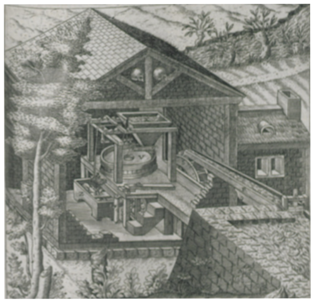
In the historical context of reference, the mill was often not only the place where grinding took place but also served as a warehouse and as the home of the miller, his family, and any workers. It was therefore common for these to be masonry structures, as seen in Figure A4. However, given the scale of Leonardo’s design (featuring a pendulum alone measuring 17 m, to which the additional heights of the transmission system, the millstone, a standing operator, and the roof must be added, resulting in a total height of approximately 25 m) a timber construction appears to be a more viable solution. This would have been significantly less expensive and more accessible within the practical and economic context in which such a mill would have been built.
Figure A4. Agostino Ramelli—Le diverse et artificiose machine Page 185r (1588).
Heritage 08 00497 g0a4
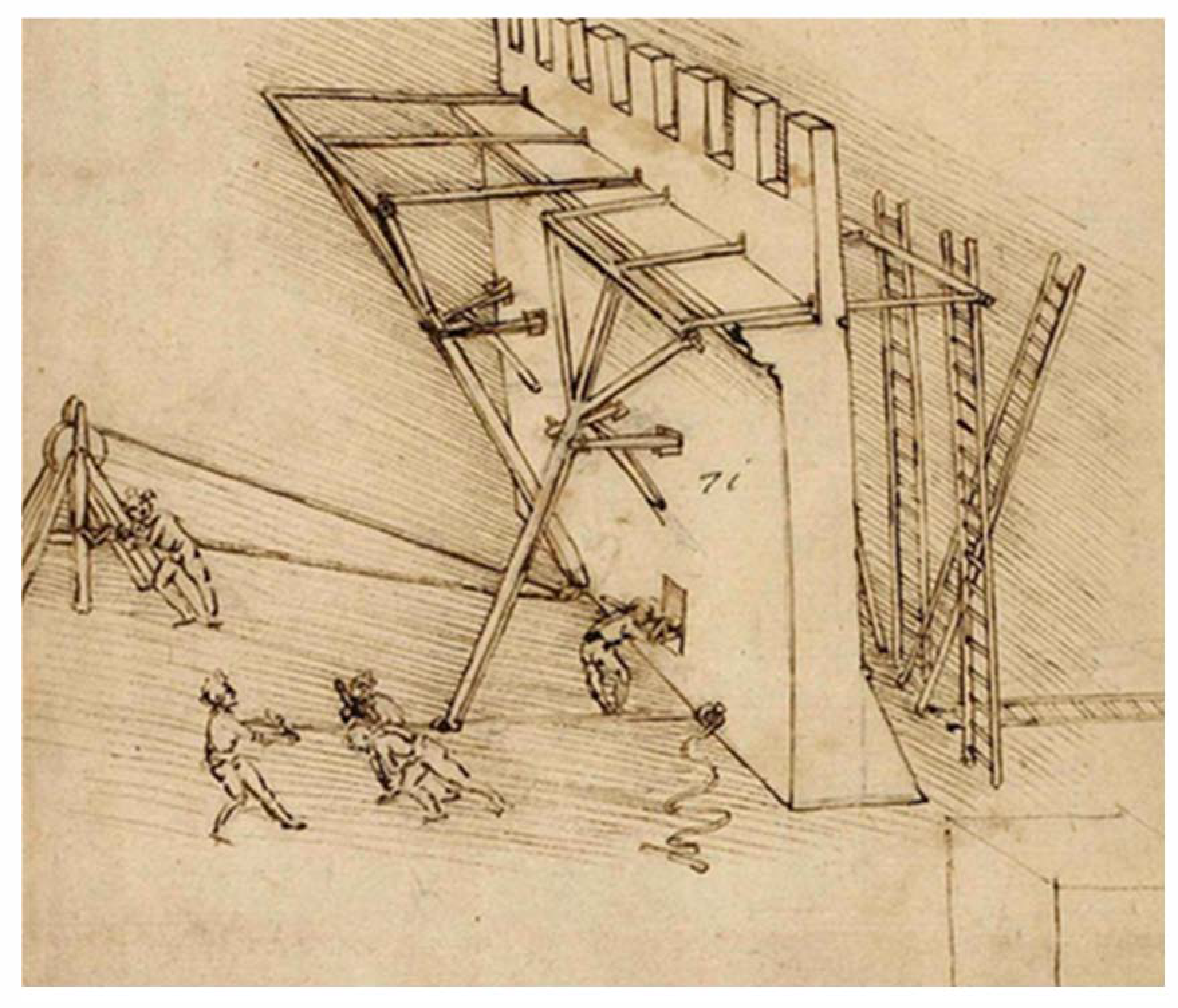
We do not exclude the hypothesis of a structure built on a natural slope or anchored to an existing building, as seen in the following examples:
Figure A5. Codex Atlanticus, Sheet 89r (1478–1480) [13].
Heritage 08 00497 g0a5
Figure A6. Codex Atlanticus, Sheet 139r (1480) [13].
Heritage 08 00497 g0a6
Figure A7. Francesco Di Giorgio Martini—Opusculum de architectura, Sheet 60v (1475–1478).
Heritage 08 00497 g0a7
Figure A8. Taccola—Liber teritus de ingeneis de edifitius non usitatis Sheet 7v—Dead water mill (1432).
Heritage 08 00497 g0a8
Given the premises outlined above, and considering that the structure in Figure A3 was conceived to accommodate a pendulum of the same length (though with a different weight), we hypothesize that the supporting structure of the pendulum mill follows the design represented in Figure A3.
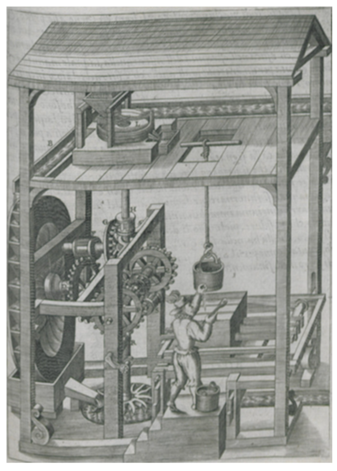
From the proposed solution of a wooden framework, as shown in Figure A3, it is clear that a system is required to facilitate the ascent of the grain and the descent of the milled product. Several possible solutions could be considered, ranging from simpler mechanisms, like the one depicted in Figure A9, to more complex ones as illustrated by Leonardo in the subsequent examples.
It is also conceivable that the mill’s location could be on the same level as a raised embankment or an elevated floor, in contrast to the position of the pendulum. However, Figure A9 suggests that the mill’s platform could be situated at a different level than the mechanisms for power transmission and system regulation.
Figure A9. Agostino Ramelli—Le diverse et artificiose machine, Page 210r (1588).
Heritage 08 00497 g0a9

Appendix A.2. Document Linked to the PSN Info-Box About the Principle of the Pendulum
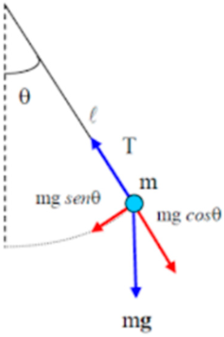
To understand the physical laws that govern the operation of a pendulum, we first analyze the simple pendulum, which is a physical system consisting of a point mass m, suspended from an inextensible string of negligible mass.
The simple pendulum is a physical system that follows the model of a harmonic oscillator, meaning it is described by the laws of harmonic motion. The characteristic that is most interesting to us is the one involving a restoring force proportional to the displacement from its equilibrium position.
At the equilibrium position, the vertical component of the weight (mg), according to Newton’s law of gravitation, is balanced by the tension in the string (T). Therefore, the point mass m is stationary, and the string is taut along the vertical, as Leonardo described: “The suspended weight is completely and entirely along the central line of its suspender” (sheet 313v, Atlantic Codex, 1514-15). However, when the mass is displaced from this equilibrium position, the weight acquires a tangential component (mg sin θ) along the direction of oscillation and a radial component (mg cos θ) perpendicular to it, as shown in Figure A10. The radial component of the tension in the string balances the radial component of the gravitational force and maintains the circular motion. The tangential component of the gravitational force, on the other hand, is what we call the restoring force, as it tends to bring the pendulum back to its equilibrium position, generating oscillatory motion. Dissipative forces, however, slow down and eventually stop the oscillation over time.
On an energetic level, the pendulum gains gravitational potential energy when it is displaced from its equilibrium position, and this energy is transformed into kinetic energy when it is released. In a real system, dissipative forces, such as air resistance, act against the motion of the pendulum, gradually reducing the total mechanical energy of the system until the pendulum comes to rest in its equilibrium position.
Figure A10. Schematic representation of the Simple Pendulum.
Heritage 08 00497 g0a10
Leonardo conducted many studies on pendulums, and we have numerous testimonies that attest to his knowledge in this field. For example, in sheet 773v of the Atlantic Codex from 1499, he states about the oscillating weight: “The motion that goes back and forth, made by the weight attached to a single string, will immediately cease when moving across its upper end of the string. Is it upward or downward?”
Or as we can read in sheet 904v of the Atlantic Codex from 1513: “Every parallel weight, suspended obliquely outside the center of its gravity, has a motion disposed towards two aspects, one of which leads to the center of the world, the other towards the destruction of its obliquity.”
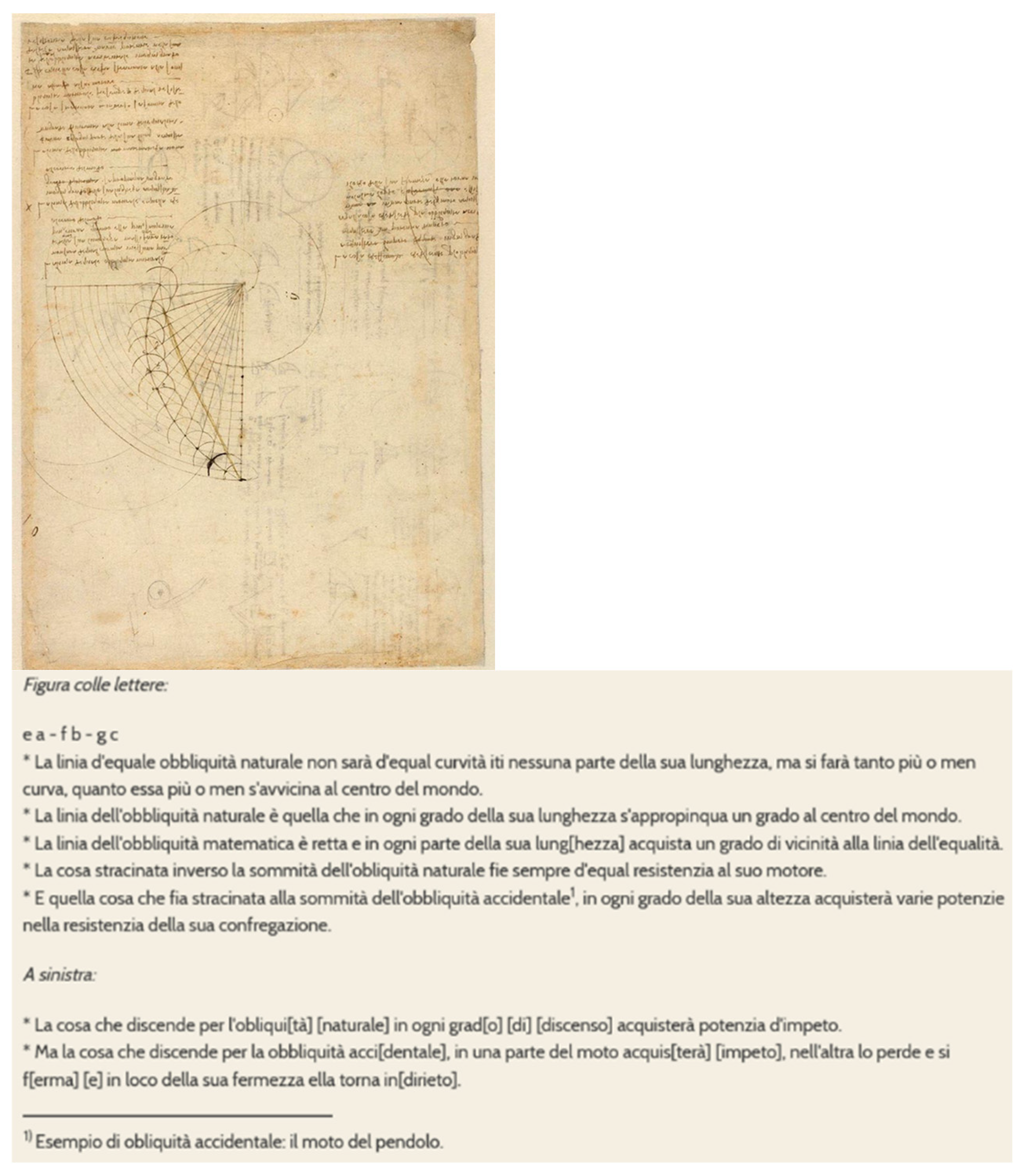
Finally, as we can see in the example of Figure A11, where Leonardo studies and describes the motion of the pendulum, which he often refers to as “accidental obliquity.”
Figure A11. Codex Atlanticus, Sheet 343r (1505) [13] and related text [17].
Heritage 08 00497 g0a11

Appendix A.3. Document Linked to the PSN Solution-Box About the Pendulum Mill
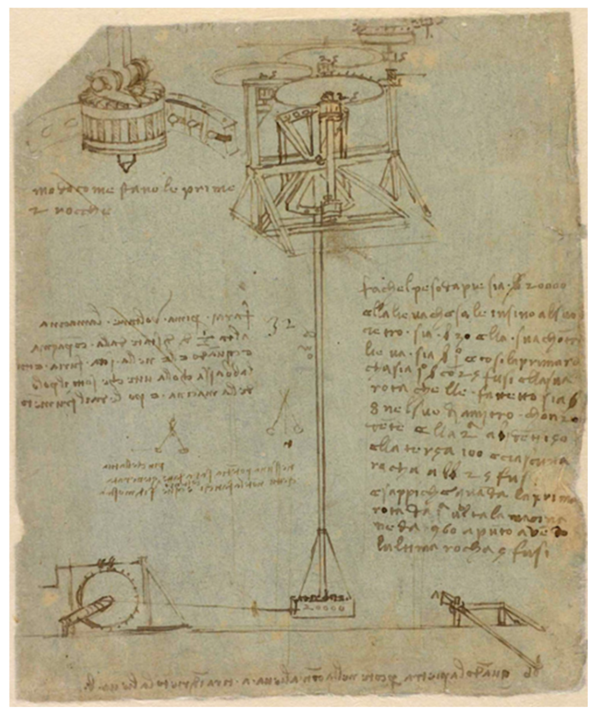
Leonardo, for the pendulum mill, represents and describes the pendulum as follows:
Figure A12. Codex Atlanticus, Sheet 170r (1513) [13].
Heritage 08 00497 g0a12
Providing detailed information on the dimensions and weight of the pendulum:
  • Length: 30 “braccia” (17 m) and the counterweight arm 1
  • Weight: 20,000 “Libbre” (6800 kg)
The pendulum consists of a hinged rod (lieva), presumably made of wood, and a hanging mass (composed of a stone as indicated in the same sheet: “when the stone strikes”) tied and supported, probably like the one in Figure A13:
Figure A13. Codex Atlanticus, Sheet 20r (1487) [13].
Heritage 08 00497 g0a13
Other construction hypotheses can be made starting from Leonardo’s other sketches of the pendulum mill, arranged chronologically (the reference sheet is dated 1513 and is the last known representation by Leonardo of the pendulum mill):
Figure A14. Codex Atlanticus, Sheet 1059r (1480) [13].
Heritage 08 00497 g0a14
Figure A15. Codex Atlanticus, Sheet 1052, (1485) [13].
Heritage 08 00497 g0a15
Figure A16. Codex Atlanticus, Sheet 1065r, (1485) [13].
Heritage 08 00497 g0a16
Figure A17. Forster I Codex, Sheet 46r (1480–1497) [15].
Heritage 08 00497 g0a17
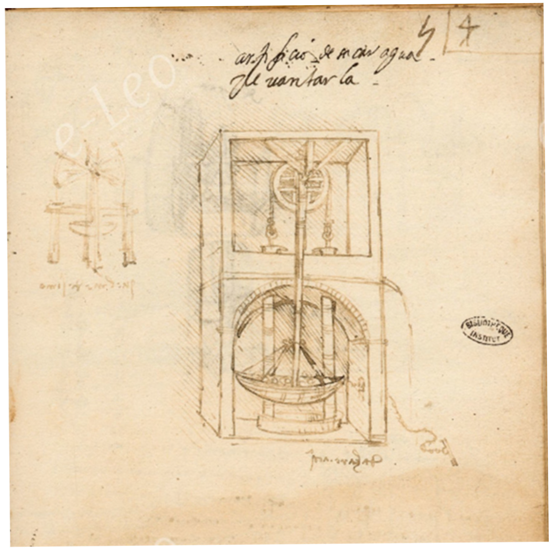
Another source of inspiration could be the pendulum pumps, like the one in Figure A18:
Figure A18. Manuscript B of the Institut de France, Sheet 54r (1487-89) [27].
Heritage 08 00497 g0a18

Appendix B

Schematic Representation of the Gear Train of the Mill Shown in Figure 8 (Section 4)

Figure A19. The Gear Train of the Mill Shown in Figure 8 (Section 4).
Heritage 08 00497 g0a19

References

  1. Galluzzi, P. Leonardo Da Vinci: From the “Elementi Macchinali” to the Man-Machine. Hist. Technol. 1987, 4, 235–265. [Google Scholar] [CrossRef]
  2. Nanni, R. Leonardo and the Artes Mechanicae; Skirà: Milano, Italy, 2013. [Google Scholar]
  3. Kemp, M. Leonardo Da Vinci: The Marvellous Works of Nature and Man; Oxford University Press: Oxford, UK, 2007. [Google Scholar]
  4. Pedretti, C. The Literary Works of Leonardo Da Vinci; California University Press: Berkeley, CA, USA, 1977; Volume 1. [Google Scholar]
  5. Foley, V.; Sedlock, D.; Widule, C.; Ellis, D. Besson, Da Vinci, and the Evolution of the Pendulum: Some Findings and Observations. Hist. Technol. 1988, 6, 1–43. [Google Scholar] [CrossRef]
  6. Vezzosi, A.; Sabato, A. The New Geneaological Tree of the Da Vinci Family for Leonardo’s DNA. Ancestors and Descendants in Direct Male Line down to the Present XXI Generation. Hum. Evol. 2021, 36, 1–90. [Google Scholar] [CrossRef]
  7. Galluzzi, P. Gli Ingegneri Del Rinascimento Da Brunelleschi a Leonardo Da Vinci; Giunti: Firenze, Italy, 1996. [Google Scholar]
  8. Galluzzi, P. Prima Di Leonardo: Cultura Delle Macchine a Siena Nel Rinascimento; Electa: Milano, Italy, 1991. [Google Scholar]
  9. Fiorineschi, L.; Rotini, F.; Barsanti, R. Systematic Design of Ancient Machines ’ Models: Leonardo Da Vinci’ s Glider. Heritage 2022, 3, 1593–1611. [Google Scholar] [CrossRef]
  10. Arrighi, V. Leonardo Da Vinci: Alle Origini Del Genio; Barsanti, R., Ed.; Giunti: Florence, Italy, 2019. [Google Scholar]
  11. Leonardo//Thek@. Available online: https://teche.museogalileo.it/leonardo/home/ (accessed on 20 August 2025).
  12. Arte Leonardiane. Available online: https://dataleonardo.labdilef.it/ (accessed on 20 August 2025).
  13. Codice Atlantico Leonardo Da Vinci. Veneranda Biblioteca Ambrosiana. Available online: https://ambrosiana.it/scopri/codice-atlantico-leonardo-da-vinci/ (accessed on 14 November 2025).
  14. | BNE | National Library of Spain. Available online: https://www.bne.es/es (accessed on 14 November 2025).
  15. The Family of Art, Design and Performance Museums · V&A. Available online: https://www.vam.ac.uk/?srsltid=AfmBOoqJP6p0bprJ6tUQwW-J9poLgvz5FcvxTgFndxDw2N1U9Plm9oNc (accessed on 14 November 2025).
  16. Addomine, M. L’orologio Astronomico Di Chiaravalle. La. Voce di Hora 2007, 1–14. [Google Scholar]
  17. E-Leo. Digital Archive of History of Technology and Science. Available online: https://www.leonardodigitale.com/en/ (accessed on 20 August 2025).
  18. Cardarelli, F. Encyclopaedia of Scientific Units, Weights and Measures; Springer: London, UK, 2003; ISBN 9781447111221. [Google Scholar]
  19. Fiorineschi, L.; Rotini, F.; Rissone, P. A New Conceptual Design Approach for Overcoming the Flaws of Functional Decomposition and Morphology. J. Eng. Des. 2016, 27, 438–468. [Google Scholar] [CrossRef]
  20. Fiorineschi, L. Abstraction Framework to Support Students in Learning Creative Conceptual Design. J. Eng. Des. Technol. 2018, 16, 616–636. [Google Scholar] [CrossRef]
  21. Dorst, K.; Vermaas, P.E. John Gero’s Function-Behaviour-Structure Model of Designing: A Critical Analysis. Res. Eng. Des. 2005, 16, 17–26. [Google Scholar] [CrossRef]
  22. Purcell, A.T.; Gero, J.S. Design and Other Types of Fixation. Des. Stud. 1996, 17, 363–383. [Google Scholar] [CrossRef]
  23. Gero, J.S.; Kanessegiesser, U. The Situated Function–Behaviour–Structure Framework. Pdf. Des. Stud. 2004, 25, 373–391. [Google Scholar] [CrossRef]
  24. Pahl, G.; Beitz, W.; Feldhusen, J.; Grote, K.H. Engineering Design, 3rd ed.; Springer: London, UK, 2007; ISBN 9781846283185. [Google Scholar]
  25. Fiorineschi, L. Problem-Solution-Network of the Leonardo Da Vinci’s Glider. Mendeley Data 2022, 1. [Google Scholar] [CrossRef]
  26. Fiorineschi, L.; Rotini, F.; Barsanti, R. Leonardo Da Vinci’s Pendular Mill: Towards a Physical Model for Museum’s Exhibits. Lect. Notes Mech. Eng. 2024, 479–487. [Google Scholar] [CrossRef]
  27. Bibliothèque de l’Institut de France | Bibliothèque de l’Institut de France. Available online: https://www.bibliotheque-institutdefrance.fr/ (accessed on 14 November 2025).
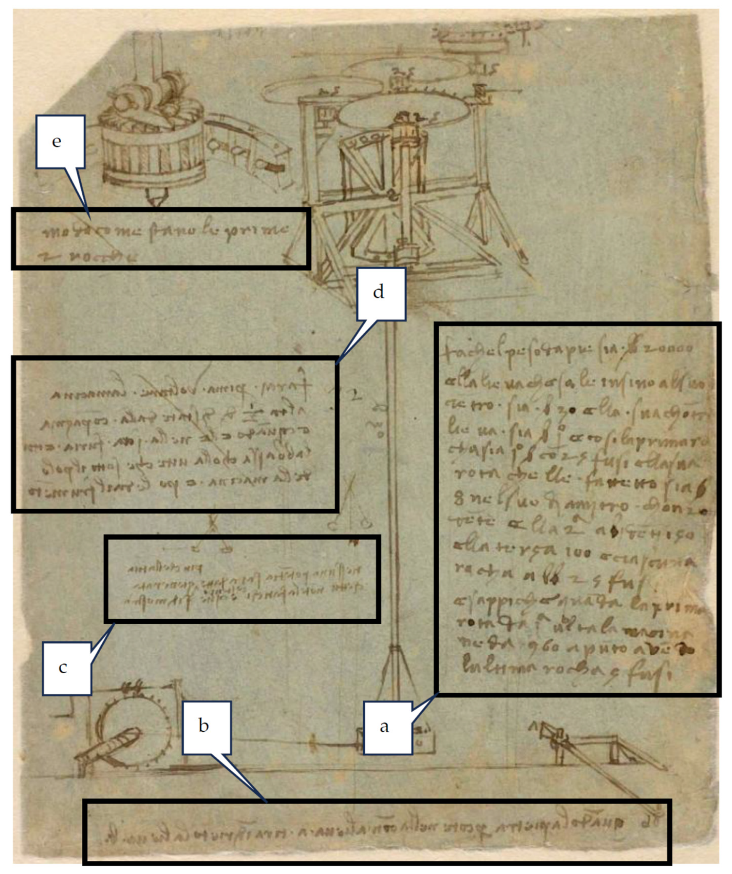
Figure 2. Text contained in the sheet 170r, Codex Atlanticus [13]. See Table 1 for the contents indicated by the letters.
Heritage 08 00497 g002
Figure 3. Graphical details contained in the sheet 170r, Codex Atlanticus [13]. See the paragraphs below for the explanation of the details indicated by the Greek letters.
Heritage 08 00497 g003
Figure 4. A generic and simple representation of the PSN framework.
Heritage 08 00497 g004
Figure 5. PSN boxes classified with the FBS framework.
Heritage 08 00497 g005
Figure 6. Overall view of the obtained PSN. See Table 3 for the description of the highlighted ramifications. See Table 2 for the details indicated by the letters.
Heritage 08 00497 g006
Figure 7. Partial view of the PSN (compacted), in relation to the sub-ramification “d-1” in Figure 6, which concerns the energy source of the Mill (i.e., the pendulum). See Table 3 for the description of the boxes. See Table 3 for the explanation of the nodes indicated by the letters.
Heritage 08 00497 g007
Figure 8. Three-dimensional reconstruction of the gear transmission of the pendulum mill. Front view.
Heritage 08 00497 g008
Figure 9. Removable pins for the hourglass-shaped wheel.
Heritage 08 00497 g009
Figure 10. Escapement mechanism.
Heritage 08 00497 g010
Figure 11. CAD model of the whole milling plant.
Heritage 08 00497 g011
Figure 12. Side view of the upper part of the plant.
Heritage 08 00497 g012
Table 1. Translation from e-leo platform [17] of Sheet 170r from the Codex Atlanticus.
DetailTranslation
a“Ensure that the weight at the bottom is 20,000 pounds, and the lever that rises to its center is 30 arms long; its counter-lever is one arm. The first spindle is one arm with 25 teeth, and the wheel above it, serving as a cover, is 8 arms in diameter with 200 teeth; the second wheel has 150 teeth, and the third 100. Each spindle has 25 teeth. Know that when the first wheel makes one turn, the millstone makes exactly 960, with the last spindle having 5 theet.”
b“When the stone strikes the counter-lever at a, it pulls back the lever b.”
c“No power will exceed that which you generate yourself, unless you exert effort over time, and this is demonstrated here.”
d“First, make the millstone turn half a braccio above its counterpart, and when it gains momentum, lower it with the screw beneath the millstone’s axis, then feed it grain.”
e“Arrangement of the first two spindles.”
Table 2. Main ramifications of the PSN.
PSN
Ramification
Description
aThis very simple ramification is related to the functional problem “How to fix the system to the ground?”. Only a pink box (i.e., information-related box) is connected to the problem box, since no final decisions were taken by Leonardo, about how to host the whole mechanism. The document linked to the pink box has been reported in Appendix A.1, and has been used to infer an hypothetical hosting structure for the preliminary CAD model.
bThis is the ramification related to the main functional problem “How to import the grain?”. This PSN sub-network led to several solutions and related sub-problems, which allowed the authors to consider a hopper with a vibrating mechanism. Since this system was not shown in the considered sheets of Leonardo, additional documents have been taken into account, both from Leonardo and other Renaissance engineers.
cThis ramification develops from the main problem “How to collect the flour?”. Similarly to the precedent one in this table, many references have been considered, since the related sub-system was not represented in the Leonardo’s sheets about the pendulum mill.
dFor the contents of this paper, this ramification is the most critical. Indeed, it develops from the problem “How to grind the grain?”, and therefore also concerns the power source (i.e., the pendulum) used to move the stone mill. One of the key groups of PSN boxes related to this branch (d-1) will be described here in the following.
Table 3. Boxes highlighted in Figure 7.
NodeDescription
aThis is a functional problem (i.e., “F” level of the FBS construct), and concerns the transformation of the grain into flour.
bSince no alternative are possible, a direct “F-S” passage has been considered (red arrow). In fact, the specific box represents a structural solution (“S” level of the FBS construct), and actually represent the stone mill.
cThis is the principal functional problem derived by the adoption of the stone mill, i.e., related to the generation of the torque required to move it.
dThis box is a solution at the “Behaviour” level of the FBS construct. It indicates that the application of a force at a certain distance from the axle is used to generate the torque, according to basic physics rule.
eThanks to the precedent box, it is now possible to consider the specific functional problem related to the generation of the force needed to generate the torque.
fAgain, a “B”-level solution is used, in this case to indicate that Leonardo used the principle of the Pendulum in order to generate the force needed to obtain the torque for the movement of the mill.
gThis is an “info” box of the PSN, and since the text is underlined, it means that there is an hyperlink to a document concerning some specific information about the principle of the pendulum (see Appendix A.2).
hThis is a “B”-level problem, that substantially is a logical sequence of the precedent solution. Indeed, since a “B”-level solution is proposed (in this case, actually used by Leonardo), the next step is to ask how it is intended to be exploited in order to obtain the expected results.
iThis “S”-level solution actually answers the precedent question, simply by indicating the solution adopted by Leonardo. Also in this case, the text is underlined because there is an hyperlink to a document concerning the pendulum mill (see Appendix A.3).
Disclaimer/Publisher’s Note: The statements, opinions and data contained in all publications are solely those of the individual author(s) and contributor(s) and not of MDPI and/or the editor(s). MDPI and/or the editor(s) disclaim responsibility for any injury to people or property resulting from any ideas, methods, instructions or products referred to in the content.