Abstract
Amber has been used to create decorative items for centuries, but its degradation presents challenges for conservators. This study identifies substances historically used to protect amber objects, especially those from 17th and 18th century Gdansk workshops. Despite their historical value, information on amber conservation is scarce. Traditional substances are noted, but their exact compositions and effects on amber remain unclear. Synthetic resins, introduced in the late 19th century, also degrade, complicating conservation due to their removal difficulty and interference with amber identification. This research aimed to develop methods for detecting and analyzing protective coatings on amber objects using macroscopic and microscopic techniques. Initial methods included analytical photography under visible and UV light and reflectance imaging spectroscopy (RIS) to assess the surface. Raman spectroscopy (RS) and X-ray fluorescence spectroscopy (XRF) were used for detailed analysis. RS provided precise layer-specific information but was sensitive to surface conditions, while XRF quickly identified inorganic compounds but not organic materials. Examining amber objects from Polish collections using this methodology revealed various protective substances, including synthetic resins and nitrocellulose varnishes. This research contributes to amber conservation by proposing a comprehensive material analysis approach, essential for developing effective conservation strategies for these historic objects.
1. Introduction
Amber, a fossilized tree resin from the Tertiary period, is millions of years old and has significant geological and historical importance. The primary source of amber is the Baltic region, particularly along the coasts of Poland, Lithuania, and Russia, which accounts for approximately 80–90% of the global supply [1]. Baltic amber, also known as succinite, is renowned for its clarity and the presence of prehistoric inclusions, making it a valuable resource for both scientific research and historical trade. Other notable deposits are found in the Dominican Republic, Mexico, and Myanmar. The resin, originally produced by ancient coniferous trees, underwent polymerization and oxidation over millennia, resulting in the amber found today, typically within sedimentary layers near ancient coastlines and river deltas [1,2].
The historical and cultural significance of amber extends beyond its geological origins. For centuries, amber has been used to create cultural heritage objects, ranging from primitively made beads and pendants from thousands of years ago to masterpieces of craftsmanship in the form of intricately made decorative arts objects. However, conservators face the ongoing challenge of amber degradation and the preservation of these artifacts. Cultural institutions must address the deterioration of amber to ensure the longevity and integrity of these historically significant objects.
This topic has been widely discussed in the specialized conservation literature [3,4] and has also been addressed by specialists in the field of chemistry [5,6,7,8,9]. The problem is very complex and depends on the material and the conditions in which the object is stored. Environmental elements such as light, oxygen, and humidity affect the state of amber preservation. Because of contact with these factors, amber becomes dull, cracked, brittle, and transparent, and its varieties tarnish. It has been reported that conservation is often needed for both archaeological objects deposited for many years in the ground and pieces of decorative art kept for many years as decorations on an exposed, well-lit site.
Amber art has been developing on the southern coast of the Baltic Sea for centuries, but a unique period called the Golden Age [10] occurred in the 17th and 18th centuries. The most important city was Gdansk, but centers in Kaliningrad and northern Germany are also known. The masterpieces made from amber during this period are unique. They are items of decorative art such as cutlery and rosaries, as well as home altars, caskets, and game boards. These objects were made upon requests of royal courts and wealthy burghers. For the most part, these objects are made of many elements and different types of materials. While the structure’s skeleton is wooden, possibly reinforced with metal rods, besides many amber elements (tiles, carvings, and bas-reliefs), ivory was also used for decoration. A common decorative procedure was to place metal tiles under the transparent amber where ornaments were made using the intaglio or eglomise technique. The whole structure of these decorative elements was usually fixed with protein glue, using paper and parchment to underlay the elements.
Currently, objects of this type are in the collections of very few European museums [11,12,13]. In Poland, the largest collection is housed at the Gdansk Museum in the branch of the Amber Museum [14] and the Castle Museum in Malbork [15]. The objects presented in this paper belong to these two collections.
The existing literature discussing the problem of amber conservation is not very extensive. On the one hand, this is a rather difficult and non-obvious subject, but conservators specializing in amber conservation do not typically share their knowledge and experience. Many of the conservation methods developed are not published and are noted only, often briefly, in museum reports. The most comprehensive articles are those published by Thickett [4] and Beck [3]. They mention preparations such as “oil of amber,” although noting that its composition is unknown and application to amber may affect its identification as Baltic or non-Baltic. The traditional and natural substances mentioned are paraffin and beeswax, Canada balsam’s xylene solutions, damar turpentine solutions, and shellac, among others.
Since the late 19th century, synthetic resins have also been used. They can include polyvinyl acetates, acrylic resins, cellulose nitrate, Mowilith 30 and 35/73, poly(vinyl chloride), celluloid, and methacrylates (Paraloids). Moreover, when exposed to light and air, they also degrade, dull, and crack, and they are difficult to remove. Some can interfere with the porous layer and migrate into the interior of the amber [4]. Also, the mixture of gelatin and glycerol mentioned in the article [3], while easily removable, tarnishes within a few years.
The problem is that such resins can interfere with amber identification, so Beck [3] suggests using only materials with no absorption in the 1100–1250 cm−1 region, which is the area used to identify and determine the chemistry of amber objects.
Unfortunately, some internal museum manuals recommend using artificial resin for artistic objects, which is a highly debatable topic. As mentioned above, in many cases, such a layer is indelible and has many challenging outcomes for the object, and its identification is often a difficult process.
A separate issue is the conservation of inclusion-containing amber. This topic was recently discussed in [16,17]. In contrast, the conservation of amber from underwater finds requires quite a different methodology. These topics are not covered in this article.
In this context, the development of a conservation program for such complex amber objects requires an in-depth material analysis. It is necessary to identify the amber or its imitations, the layers of protection and the adhesives used, and other materials used for constructing the object.
Identification of amber is not a simple task [18,19,20,21]. Caldararo et al. [19] have divided identification methods in two categories: traditional and instrumental. Most of the techniques mentioned in their paper, such as hot needle test, knife test, melting point test, solvent test, refractive index, and density test, require sample collection. Unfortunately, a skilled forger can be successful in deceiving these methods [3]. Moreover, many instrumental techniques like FTIR (excluding the rarely used DRIFT (Diffuse Reflectance Infrared Fourier Transform Spectroscopy)), the reflectance technique [20,21], or chromatographic techniques [22] also require sampling. For the majority of cultural heritage objects, extracting samples is an unacceptable practice. Moreover, when an object is composed of multiple amber elements, such as in the present case study, taking a sample from a single element does not provide answers about the state of preservation of the remaining fragments.
This study proposes a different analytical approach involving, first, the use of macroscopic techniques, and then focusing on selected fragments, which were examined using microscopic techniques. The first group of macroscopic methods includes technical photography (in the UV-VIS-IR ranges). Ultraviolet-induced fluorescence (UVIF) imaging is of particular importance as it helps with the identification of amber. In addition, hyperspectral imaging allows for the analysis of the surface characteristics of a larger area (preferably the entire object) during the measurement. Microchemical methods include Raman spectroscopy (RS) and X-ray fluorescence spectroscopy (XRF), where a single measurement gives information at the micrometer scale.
A macro survey allows for the obtaining of knowledge of the object’s state of preservation and the ability to locate previous conservation interventions. The results obtained are influenced by the degradation of the amber and the presence of layers on the surface. For example, the blue fluorescence of amber under UV radiation is best seen on freshly broken amber [19,23]. UV photographs allow areas of intrusion to be illustrated in real-time, although it should be remembered that some substances do not show a characteristic fluorescence under UV radiation. This can lead to erroneous conclusions. Moreover, UV radiation allows for the evaluation of changes that have occurred on the surface of objects, but identification is possible only in exceptional cases (e.g., amber and shellac).
Reflectance imaging spectroscopy (RIS) is a common method used for the analysis of works of art, especially paintings. This is due to its many advantages, i.e., (1) the ability to perform an area-based measurement, which involves the potential acquisition of material distribution information [24,25,26]; (2) a relatively short measurement time (as short as a few/ten minutes for the entire object) [27]; (3) the ability to identify and differentiate a wide range of materials, including pigments and binders [24,25,26], but also other materials that may have been used in the creative process [28,29,30].
Despite the widespread use of the RIS method in assessing material quality in various industrial processes [31,32,33,34], due to some difficulties in data analysis, especially unlabeled data, where a priori knowledge is often unavailable, the technique is only beginning to be exploited in the analysis of cultural heritage objects other than paintings [35,36]. Nevertheless, as shown in [37], RIS performed in imaging mode can be a valuable tool in the study of amber objects, enabling the mapping of conservation interventions and the assessment of material variation. Also, within the amber itself, it is possible to detect differences in the state of preservation and the potential determination of the type of amber used.
In the next step, the areas selected for microscopic analysis were selected based on the results of the macro studies. Raman spectroscopy and XRF spectrometry were used complementarily, as both have advantages and disadvantages. It should be noted that XRF measurements usually require less time than those taken using Raman spectroscopy. For example, one XRF measurement, which collects information through all sample layers, takes about a minute. In contrast, one depth profiling with a confocal Raman microscope (according to the parameters described in the present experiment) takes more than 8 min. However, with Raman spectroscopy, it is possible to define the measurement layer. Unfortunately, Raman spectroscopy is more sensitive to laser focus, surface characteristics, and impurities. Moreover, not all compounds in a sample give signals of comparable intensity, which can lead to misinterpretations. On the other hand, XRF is unsuitable for identifying the presence of organic compounds. This technique cannot identify both amber and organic compounds used for preservation (resins, varnishes). Pure amber consists exclusively of organic compounds, including elements such as carbon, oxygen, hydrogen, and sulfur, of which only sulfur is detectable by XRF spectroscopy [38]. Other elements, especially metals, indicate the presence of a layer of paint with a pigment or filler, such as chromium, barium, or titanium compounds, or identify cavity restorations in which the fillings used are colored or with the aforementioned pigments or form a plastic mass such as gypsum. Unfortunately, for substances that contain elements outside the XRF detection range, Raman spectroscopy remains the only means of identification. Moreover, the identification of organic compounds, especially polymers, by Raman spectroscopy is widespread, including in the field of heritage science [39,40,41,42].
In this paper, the authors would like to address the problem of identifying substances used to protect amber objects during earlier restorations. This study focused on objects from workshops in Gdansk from the 17th to the 18th century. The research aim of this paper was to develop and implement a methodology that can be used to analyze protective coatings on amber objects. The proposed methodology can also be applied to other protective coated surfaces.
2. Materials and Methods
2.1. Investigated Artifacts
Maucher’s casket is displayed at the Castle Museum in Malbork [15,43]. It is one of the most valuable amber objects created in the modern period, made by one of the most outstanding 17th century amber artists, Christoph Maucher. The Malbork casket is characterized by its high artistic class and craftsmanship.
Another group of objects comes from the collection of the Amber Museum, a branch of the Gdansk Museum [44]. The investigated plaque is a unique object in the Amber Museum’s collection. Its authorship is attributed to the brothers Christopher Maucher or Johann Michael Maucher. It is set on a wooden base and was secondarily framed, while originally, it was the bottom of a large casket. It is secular in nature and uses decorative techniques typical of Gdansk workshops.
The chessboard under investigation dates from the late 17th century, probably from the workshop of Michael Redlin [45]. It is a decorative, finely worked casket providing a planchet for 32 preserved figures (not examined). The planchette was made of appropriately selected transparent and milky amber, and the whole thing is decorated with cabochons.
The house altarpiece with a crucifix (referred from this point on as crucifix) comes from a Gdansk workshop from the late 17th century and is a typical example of Gdansk wares. It has a three-story wooden structure tightly clad with amber tiles.
2.2. Technical Photography
Technical photography was used to document a cabinet and a crucifix, encompassing visible light (VIS) and ultraviolet-induced fluorescence (UV). Images were recorded in JPG, RAW, and TIF formats. Visible light photography (VIS) was carried out using a Canon EOS 5D Mark III camera with a Canon Macro EF 100 mm, 1:2.8. USM lens, under halogen illumination (two columns with 2 × 125 + 2 × 150 W), with exposure parameters set to 1/2 s; f/16; ISO 100. Ultraviolet-induced fluorescence (UVIF) photography involved using a Canon EOS 5D Mark III camera with the Canon Macro EF 100 mm, 1:2.8. USM lens. Images were captured using 4 × Philips TL-D 36W/BLB UV fluorescent lamps (368 nm), with exposure parameters set to 60.0 s; f/16; ISO 100. Halogen illumination (two columns with 2 × 125 + 2 × 150 W) was employed, with exposure parameters set to 1/20 s; f/8; ISO 100. Subsequently, post-acquisition images underwent meticulous editing, including white balance adjustment, cropping, and color analysis, using Adobe Photoshop 2023 and Capture One Pro. Exposure and white balance were calibrated using an X-Rite ColorChecker Passport for accurate results (https://www.xrite.com/categories/calibration-profiling/colorchecker-classic-family/colorchecker-passport-photo-2; accessed on 22 July 2024).
2.3. Reflectance Imaging Spectroscopy (RIS)
The measurement was carried out using an imaging system with short wavelength infrared reflectance spectroscopy (SWIR 1000–2500 nm, 256 spectral channels, spectral resolution 6.32 nm; Specim, Oulu FIN, https://www.specim.com/products/swir/; accessed on 22 July 2024). The system is equipped with six-point halogen light sources arranged symmetrically on both sides of the camera at an angle of 45° [46]. The scanning system was positioned in vertical geometry (Figure 1). The scan parameters were different for each scan to obtain good-quality images: exposure time 3.3–4.8 ms, repetition frequency 9 Hz, and camera movement speed 1.31–4.9 mm/s. The obtained hyperspectral images were normalized to the white (Spectralon white plate, Labsphere, North Sutton, NH, USA, https://www.labsphere.com/product/spectralon-reflectance-targets/; accessed on 22 July 2024) and reduced with dark current. Reference and dark current measurements were taken using the same parameters as for the actual object’s measurements. Fourteen scans were performed, which were then cropped and stitched using the Scale Invariant Feature Transform (SIFT) algorithm [47]. The final image was segmented to eliminate glossy areas (signal saturation), areas where it was not possible to achieve adequate sharpness to obtain high-quality spectra, and to remove background and signals not related to amber (e.g., ivory plaques areas). Data analysis was performed using self-developed scripts written in Python (Python Software Foundation. Python Language Reference, version 3.11.7).
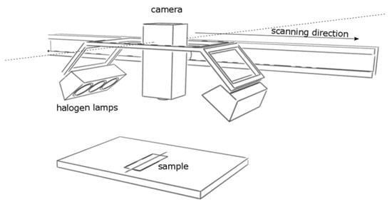
Figure 1.
Schematic of the reflectance spectroscopy imaging system.
2.4. X-ray Fluorescence (XRF) Spectroscopy
The elemental composition of the objects under question was analyzed using an ARTAX 800 portable XRF spectrometer (Bruker, Berlin, Germany, DE, https://www.bruker.com/; accessed on 22 July 2024). This spectrometer comprises a 50 kV Rh excitation tube, a Peltier-cooled silicon drift detector (with an energy resolution of 135 eV at the Mn Kα excitation line), and multiple polycapillary lenses that generate an irradiated spot with a diameter below 100 μm. This instrument facilitates the determination of elements ranging from aluminum (Al) to uranium (U). The tube voltage and anode current measurement settings were configured at 50 keV and 0.6 mA, respectively, with an acquisition time of 60 s. A laser and CCD camera were employed and integrated with the spectrometer to focus the beam on each analyzed spot. The acquisition and evaluation of XRF spectra were performed using Spectra 5.3 software (Bruker, DE, https://www.bruker.com/en/products-and-solutions/elemental-analyzers/xrf-spectrometers/xrf-software.html; accessed on 22 July 2024).
2.5. Raman Spectroscopy (RS)
Micro-Raman analyses were carried out using a multichannel bench Renishaw InVia spectrometer (Renishaw, Wotton-under-Edge, UK, https://www.renishaw.com/en/invia-confocal-raman-microscope--6260; accessed on 22 July 2024) coupled with a Peltier-cooled CCD detector and a Leica DMLM confocal microscope (https://www.leica-microsystems.com/; accessed on 22 July 2024). Acquisitions were obtained with a 1200 l/mm grating. Excitation was provided by the 785 nm line of a diode laser with an optimized laser power of about 25 mW to maximize the possible signal while avoiding causing any damage to the object. Both optical microscopic observations and the absence of changes in the Raman spectrum prove that the laser power used was appropriate.
Measurements were performed on the amber cabinet and crucifix using a steerable arm (Figure 2) due to the object’s dimensions, which prevented measurement in the microscopic observation chamber. The steerable arm enables measuring the object outside the measuring chamber through the use of an optical system placed as an objective in the microscope turret. The applied microscope objective was L50×/0.5.
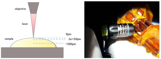
Figure 2.
Schematic of Raman depth—profiling measurements (left). Raman measurements on the amber cabinet using the steerable arm (right).
Raman depth profiling was also performed (Figure 2). Scans were collected from the surface (0 μm) to a depth of −200 μm, with a step of 50 μm, giving five spectra for a single depth profiling. The zero level was defined at the optical focus point. Every spectrum was collected using an accumulation of 100 scans with an accumulation time of 1 s. Spectra were collected in the range 750–1850 cm−1. The spectra were preprocessed before analysis using the WiRE 5.2 software (Renishaw, UK). The cosmic rays were removed, and a smoothing procedure was applied. Then, a background correction that uses an intelligent polynomial algorithm was used.
We have successfully applied this depth profiling procedure in previous studies [48]. The scanning profile is then made deep enough to determine whether amber is under the impregnation layer or whether the studied material was introduced as part of a restoration treatment. At the same time, it should be noted that this method is suitable only for the indicative determination of layer thickness.
3. Results and Discussion
The examined objects were made available for research for a relatively short time (e.g., a week). These are complex multi-element objects, consisting of at least dozens of amber elements and many elements made of other materials such as ivory, wood, minerals, and any reconstructions and additions. It is borderline impossible to measure all the elements of each object precisely. Therefore, during the measurements, after the initial recognition of the construction of a particular object, it was decided to focus on conservation interventions. To this end, analytical photographs were taken under visible and UV light. Measurements were also made using reflectance imaging spectroscopy. Based on the results, sites were selected for measurements using microscopic techniques.
3.1. Macro Techniques
Presented below are a set of analytical images and results from reflectance imaging spectroscopy for the four objects in question: an amber plaque (Figure 3, Figure 4 and Figure 5), a chessboard (Figure 6 and Figure 7), a casket (Figure 8, Figure 9 and Figure 10), and a crucifix (Figure 11 and Figure 12).
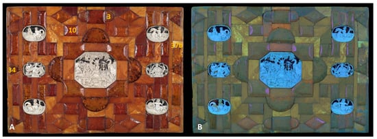
Figure 3.
Amber plaque—analytical images: (A) under visible light, including Raman and XRF measurement sites (yellow numbers) and (B) UV-induced fluorescence.
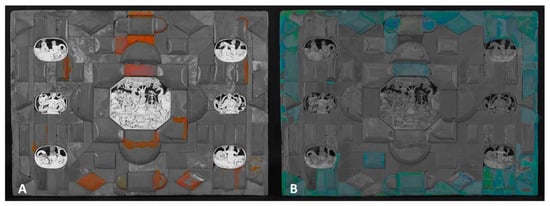
Figure 4.
A graphical representation of (A) the surface distribution of shellac and (B) synthetic resin based on ultraviolet luminescence.
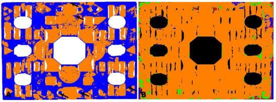
Figure 5.
Amber plaque: (A) map of the location of amber based on the Golloch’s coefficients [Equation (1)]. Orange areas are places where both coefficients did not exceed amber characteristic values; blue areas are where coefficient values exceeded the range of amber reference. Arrows indicate areas where, thanks to UV images, shellac was identified. (B) Map of the location of synthetic resin (1) (green areas), nitrocellulose mass (blue areas), and their simultaneous presence (red areas).
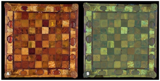
Figure 6.
Images of checkerboard in (A) visible light along with the site of Raman and XRF measurements sites (yellow number) and (B) UV-induced fluorescence.
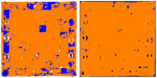
Figure 7.
Chessboard: (A) map of the location of amber based on the Golloch’s coefficients [Equation (1)]. Orange areas are places where both coefficients did not exceed amber characteristic values; blue areas are where coefficient values exceeded the range of amber reference. (B) Map of the location of nitrocellulose mass (blue areas).
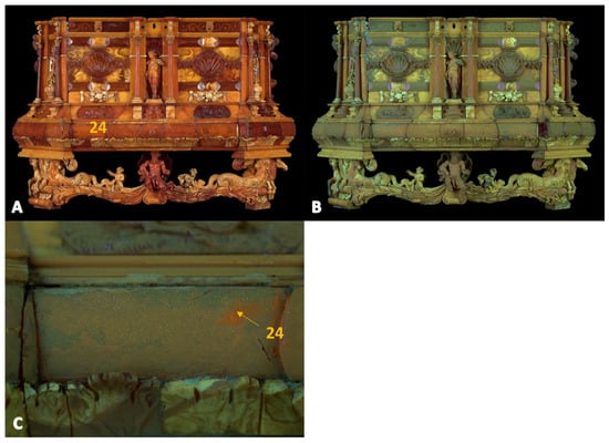
Figure 8.
Amber casket—front. Images in (A) visible light and (B) under UV. (C) The zoomed-in photo of the area shows the Raman and XRF measurement locations (yellow number).
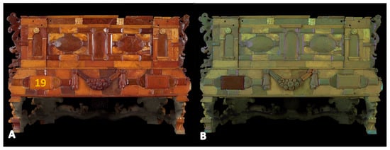
Figure 9.
Amber casket—back. Images in (A) visible light and (B) under UV. Marked location of Raman and XRF measurements (yellow number).

Figure 10.
Amber casket—front: (A) map of the location of amber based on the Golloch’s coefficients [Equation (1)]. Orange areas are places where both coefficients did not exceed amber characteristic values; blue areas are where coefficient values exceeded the range of amber reference. Arrow indicates the place where, thanks to UV images, shellac was identified. (B) Map of the location of synthetic resin (1) (green areas), nitrocellulose mass (blue areas), and their simultaneous presence (red areas).
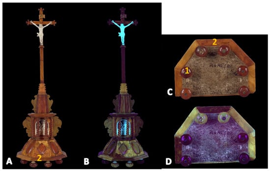
Figure 11.
Amber crucifix—images in (A,C) visible light and (B,D) under UV along with Raman and XRF measurement locations (yellow numbers). Images (C,D) show the six feet located on the bottom of the crucifix.
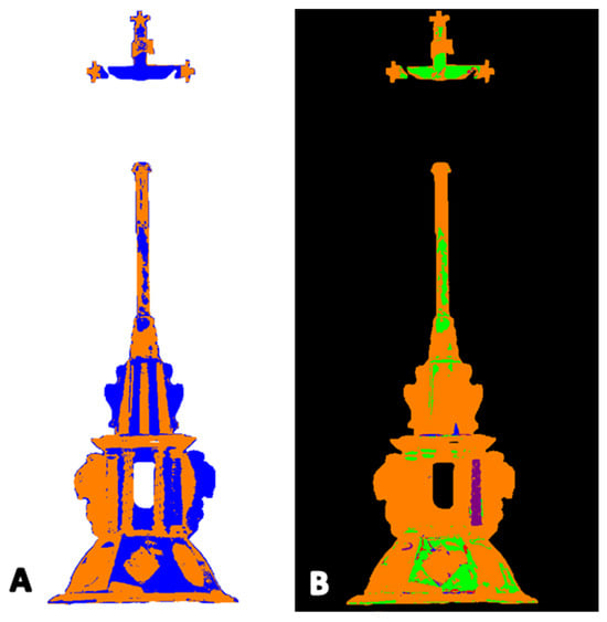
Figure 12.
Amber crucifix: (A) map of the location of amber based on the Golloch’s coefficients [Equation (1)]. Orange areas are places where both coefficients did not exceed amber characteristic values; blue areas are where coefficient values exceeded the range of amber reference. (B) Map of the location of synthetic resin (1) (green areas), synthetic resin (2) (purple areas), nitrocellulose mass (blue areas), and simultaneous presence of synthetic resin (1) and nitrocellulose mass (red areas).
The preservation state of each object was assessed using visible light. Attention is drawn to the patterns arranged from ambers of different shades. A particularly interesting case is the chessboard, where milky light ambers are arranged alternately with darker clear ones. Not all patterns are legible due to the degradation of the amber manifested by opacity.
Under UV radiation, amber has a natural greenish-blue fluorescence [23]. Unfortunately, it is not very characteristic, and its hue is influenced by the color of the amber. This can be observed, for example, in the image of the back wall of the amber casket (Figure 9).
With the help of RIS, an attempt was made to locate the amber, its imitations, and protective layers through the use of the equation proposed by A. Golloch (Equation (1)) [49]. This equation states that the ratio of 1415 and 1555 nm bands relative to 1200 and 1315 nm for amber remains specific and allows the differentiation of amber against various polymers (such as polyester resin, phenolic resin, and polystyrene). Golloch emphasizes that the proposed method does not allow for distinguishing copal from amber.
—reflectance intensities at 1415 and 1555 nm, respectively;
—reflectance intensity at 1200 nm;
—reflectance intensity at 1315 nm.
The authors are unaware of papers using the Golloch’s formula for these purposes. However, the values of the and coefficients have been reported for reference ambers [37]. The application of these values to the analysis of amber historical objects seems very promising. Comparison of the values of the coefficients determined for the object to the average values of the references makes it possible to obtain a map of the location of amber and places of doubtful identification (Figure 5A, Figure 7A, Figure 10A, and Figure 12A). The identification of amber is also supported by spectra collected from selected sites where the presence of amber was confirmed (Figure 13). The reflectance spectrum of amber shows the presence of characteristic absorption bands at about 1185 nm, 1425 nm (with the possibility of a double band of 1404 and 1440 nm), 1630 nm, a reflectance maximum at 1300 nm, and a characteristic shape of bands in the range of 1700–2120 nm associated mainly with the presence of CH and CH2 bonds and CH combination bands and O–H stretching vibration overtones [49,50,51,52].
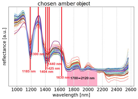
Figure 13.
Selected spectra of the amber plaque, with characteristic features in agreement with those found in reference spectra of amber.
While the locations of fillings with various plastic masses are identified rather easily, determining where amber has been coated with a protective layer is usually a challenging task. Due to the low energy of photons in the infrared range, they interact with matter less frequently than photons with higher energies. For this reason, and depending on the material under investigation; the depth of penetration; and, therefore, the signal collected as a result of the measurement can come from a significant object volume. A thin protective layer may not give a strong enough signal to be noticed in the reflectance spectrum, which can be collected even at a depth of about 1.3−2 cm in the present case. This estimation is based on observations of the details of the engraved patterns and the distorted shape of the amber spectra at the sites of metal films under amber cabochons of such thicknesses.
The sites of milky ambers present some problems at the time of interpreting the results. They often show weaker intensity of bands characteristic of amber, probably due to a significant proportion of air inclusions in their volume. Therefore, their and values do not correspond to amber reference values, and this is the reason for their frequent designation as imitations according to the Golloch’s equation.
The orange areas in the UV images are probably fragments covered with shellac, which is characterized by this color under UV radiation [53]. The orange fragments can be perfectly seen in the UV images of the amber plaque (Figure 3 and Figure 4A) and also in the enlarged photo of the casket fragment (Figure 8C). In addition, Figure 4A shows a UV image of the plaque with highlighted areas of orange fluorescence associated with the shellac (Raman and XRF measurements of this area are discussed in Section 3.2.3 Orange fluorescent shellac-type of varnish). RIS measurements showed that the shellac-bound area consists mostly of imitation sites according to the Golloch’s map (arrows in Figure 5A and Figure 10A). The reflectance spectra in these areas are characterized only by a weakening of the amber bands, with no possibility of identifying other substances.
In a similar way, an image can be enhanced (Figure 4B) to better show a bright bluish fluorescence associated with the artificial resin used to make the restorations when compared to the original UV image. These spots were further analyzed using Raman and XRF spectroscopies.
A photograph of the casket under UV radiation (Figure 8 and Figure 9) also reveals restorations characterized by bright fluorescence. In the image of the object’s back wall (Figure 9, point 19), attention is drawn to one plate characterized by a dark brown area under UV light, compared to the light greenish color of natural amber.
A similar situation is observed in the UV images of the crucifix (Figure 11). Images in visible light show a clear amber composition exhibiting different hues, while under UV, the object takes on completely different colors. This is most evident in the images of the base of the crucifix, where only two of the six legs are characterized by natural amber color under UV radiation.
Similar to technical photography, RIS also made it possible to distinguish several substances imitating amber on the surface of the studied objects. This includes two types of synthetic resins (as confirmed by the Raman measurements and discussed below in Section 3.2.2. French Ivory covering amber and Section 3.2.3. Unknown II) and a substance that includes nitrocellulose (Section 3.2.2. French Ivory covering epoxy resin). Examples of RIS spectra are presented in Figure 14.
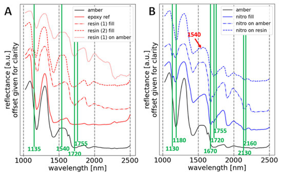
Figure 14.
Selected RIS amber spectra in relation to identified imitations: (A) reference spectrum of epoxy resin, spectra of synthetic resin fillings, and a spectrum of synthetic resin on the amber surface; (B) spectrum of nitrocellulose filling, and a spectrum of nitrocellulose varnish on the amber surface and on the surface of the resin filling (recognized thanks to the presence of the 1540 nm band).
Spectra (Figure 14A) show an absorption band with an inflection of 1135 nm, a band at 1540 nm, and a double band at 1720 and 1755 nm. These can be related to the presence of synthetic resins, which are characterized by multiple overlapping bands of CH, NH, and C=O groups [54,55,56]. Accurate identification of epoxy resin (spectrum of resin (1)) against other synthetic resins based on SWIR reflectance spectroscopy measurements is not possible in this case, probably due to the presence of amber-related bands in the spectrum as well as other processes that affect the shape of the spectrum, including degradation. The spectrum of resin (2) stands out from the spectrum of resin (1) as it does not show the 1540 nm absorption band. Raman measurements confirm the presence of an unknown substance in the area of the column under the crucifix cross (Figure 12B and also discussed in Section 3.2.3. Unknown II).
On the other hand, spectra with a specific shape in the 1430–1670 nm range (Figure 14B), which have a double absorption band of 1130 and 1180 nm and, in addition to the 1720 and 1755 nm bands, also have distinct double bands of 2130 and 2160 nm, and a band of 1670 nm can be attributed to a nitrocellulose-based substance [57]. Within selected parts of the amber plaque (red areas in Figure 5B), it was also possible to distinguish the presence of nitrocellulose varnish on the resinous filling. This was evidenced by the presence of the 1540 nm band and the weakening of the 1130 and 1180 nm bands on the spectrum, the course of which corresponds to the shape of the spectrum of the nitrocellulose mass filling.
Indicating the locations of fillings with a given substance is possible, but it is not within the scope of this paper. Obtaining a map of the location of the protective layers is difficult due to the impossibility of identifying this substance against the amber spectrum—usually, an indefinite weakening of the amber bands is observed, and only in some cases is it possible to indicate the covering material accurately (Figure 5B, Figure 7B, Figure 10B, and Figure 12B).
Using the crucifix as an example, it is possible to note the lack of sensitivity of the Golloch’s method to identify certain types of imitations in the UV-induced images (Figure 11). It can be noted that some of the cabochons with a specific violet color of quenching fluorescence, indicating imitation filling or covering with a layer of protective varnish, were not highlighted on the Golloch’s map as well as on the synthetic resin localization map. This may lead to the conclusion of the use of a different type of synthetic resin than the one previously described (Figure 14 and also discussed in Section 3.2.3. Unknown II).
Upon inspection of the images of the chessboard (Figure 6), no different colors were observed, indicating the presence of materials characterized by fluorescence under UV radiation. In this case, UV images can be misleading due to the very slight fluorescence of the varnish present on the surface. This was revealed through the Raman measurements discussed below.
It should be noted that neither UV nor RIS images identify all substances present on the surface. The Raman studies discussed in the next section revealed the presence of substances that cannot be identified based on their characteristic color under UV radiation.
3.2. Micro Techniques: Raman Spectroscopy and XRF
Based on UV images and hyperspectral imaging, it was decided to take point measurements using two microanalytical techniques: Raman spectroscopy and X-ray fluorescence.
The so-called depth profiling was performed using Raman spectroscopy. In this way, it was possible to observe how the spectral profile changes depending on the distance from the surface. The layer covering the surface can also be identified. Measurements were possible because the varnishes and amber found throughout the objects are transparent. The thickness of the layer cannot be determined by the solely use of this technique, but the method can be used to make a rough estimate.
XRF spectroscopy has made it possible to quickly identify both the substances covering the amber and the fillings by detecting elements unrelated to the presence of amber. It turns out that many preservative substances contain compounds whose constituent elements can be identified by the XRF technique. These include dyes and pigments as well as varnish fillers.
The following are examples of measurements for pure amber and amber coated with various substances, which are detectable by other techniques to varying degrees. It was mentioned in Section 3.1 that UV combined with hyperspectral imaging allowed for the identification of all areas of previous conservation treatments. Below are examples where UV images (and for most cases in RIS) did not indicate the presence of varnish, while the corresponding substance was identified based on Raman studies (Section 3.2.2). The last section of this paper describes an attempt to identify and analyze chemical compounds detected in areas characterized by intense purple fluorescence.
3.2.1. Amber
It should be noted that the spectrum of amber changes with depth from the surface. This is related to the surface degradation of amber, which was discussed in the authors’ previous article [48]. Figure 15 presents an example of the spectrum for an amber plate from the plaque (point 10, Figure 3). The change in the spectral profile is visible as measurements are taken in subsequently deeper areas. The band around 1615 cm−1 disappears, and the intensity of the 1645 cm−1 band increases. The 1615 cm−1 band is ascribed to the ν(C=C) characteristic of aromatic rings, and the 1645 cm−1 band is ascribed to the ν (C=C) of non-conjugated structures [48,58]. The intensity of the 1442 cm−1 band comes from the deformation vibration of the CH2 and CH3 groups. The bands at 1645 and 1445 cm−1 can be considered marker bands for amber.
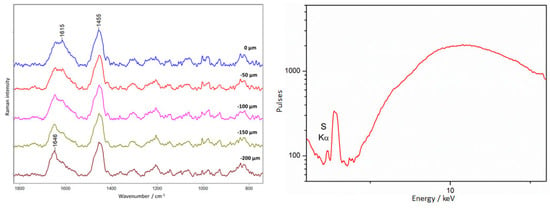
Figure 15.
Amber plaque. Example of non-covering amber. The results of Raman (left) and XRF (right) measurements were collected at point 3, according to Figure 6.
The main constituent elements of amber are carbon, hydrogen, and oxygen. XRF spectroscopy allowed for the detection of the presence of trace elements such S, Ca, and K as in most of the examined amber-clad areas (Figure 15).
3.2.2. Non-Fluorescent Area
Locations that showed no specific fluorescence were also selected for examination by Raman spectroscopy and XRF. It was expected that amber that was not coated with any preservative substances would be identified. Careful analysis of the spectra made it possible to identify several different types of varnishes and also a filling material.
- French Ivory covering amber
A layer of varnish composed of nitrocellulose, camphor, and dibutyl phthalate was identified on three of the evaluated objects: plaque, chessboard, and casket. A varnish of this composition has been described as “French ivory,” a nitrocellulose varnish popular in the 1920s [59,60], often used as a coating material.
This material is characterized by bands at 1602, 1581, and 1041 cm−1 derived from diethyl phthalate; at 1614, 1296, 1167, and 847 cm−1 attributed to nitrocellulose; and at 1724 and 1451 cm−1 derived from camphor.
Figure 16 shows the result of depth profiling of the chessboard surface at point 3 (Figure 6). There is a clear difference between the spectrum collected at the surface (0 µm), where varnish bands and amber bands are observed. There is a clear change in the profile of the amber spectra in the shoulder region at 1615 cm−1, which disappears in favor of an increase in the intensity of the 1644 cm−1 band. Only the amber spectrum is already observed for the layer measured at a depth of 50 µm.
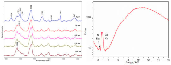
Figure 16.
Chess board. An example of French Ivory covering amber. Results of Raman (left) and XRF (right) measurements collected at point 3, according to Figure 6.
XRF measurements did not reveal any elements that could indicate the presence of varnish.
- French Ivory covering epoxy resin
A similar varnish was identified on the amber plaque, except that it was observed not only on the amber surface, but also on the restorations made of epoxy resin (Araldite 2020 type) (point 3, Figure 3). The varnish is characterized by its bluish fluorescence seen in Figure 3 and further highlighted in Figure 4. An important observation is that coating the epoxy resin with a layer of nitrocellulose varnish did not obscure the fluorescence of the resin itself.
Figure 17 presents the spectra collected from in-depth profiling. On the surface (0 µm), bands associated with the presence of French Ivory nitrocellulose varnish are visible: intense bands at 1041, 1291 cm−1, and a doublet at 1602 and 1581 cm−1. At a depth of 100 µm, bands indicative of the presence of epoxy resin [61] appear: primarily the characteristic band at 1115 cm−1, but also 1188, 1291, about 1440, and 1615 cm−1.
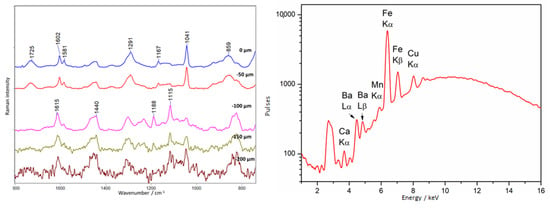
Figure 17.
Amber plaque. Example of French Ivory covering epoxy resin. Results of Raman (left) and XRF (right) measurements collected at point 3, according to Figure 3.
XRF spectra have shown that unusual elements appeared in the tested area. While the presence of the elements Fe, Cu, and Mn may be related to the presence of the brass plate under the amber, the presence of Ba is probably related to the epoxy resin filling. Perhaps the presence of Ca should also be linked to the presence of the resin, but it is a very common element, and it is sometimes present in amber.
- Medium covering amber (1002 cm−1 Raman band)
At several measured locations on the plaque, in addition to bands characteristic of nitrocellulose varnish, a rather intense band at around 1002 cm−1 was also observed. This is the region where bands associated with phenolic ring vibrations occur. In the example presented in Figure 18 recorded on the plaque shown in 37b (Figure 3), this band appears only at a depth of 50 µm, between the layers of amber on the bottom and nitrocellulose varnish in the top layer. Due to the presence of only one intense band, the identification is uncertain, but it could be an alkyd resin (e.g., Alkyd Medium 4, [62]), which has a similar spectrum due to the presence of phenolic rings in the structure. At the same time, alkyd resins are known to have been added to nitrocellulose varnishes [63].
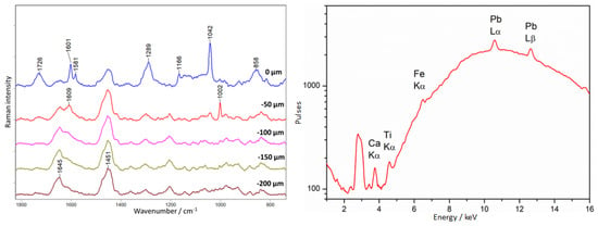
Figure 18.
Amber plaque. Example of an alkyd medium type of lacquer and French Ivory covering amber. Results of Raman (left) and XRF (right) measurements collected at point 37b, according to Figure 3.
It seems that the amber plate was first painted with a substance characterized by an intense band at 1002 cm−1, and then, perhaps in the next conservation stage, with a nitrocellulose varnish of the “French ivory” type.
XRF measurements in these areas show an unusually high titanium (Ti) content on the object’s surface. Iron and lead were also identified, but their presence may be an artifact of the presence of the metal plate under the amber plate. In Figure 19, we can observe measurements taken at point 34 of the placer (Figure 3) where the amber was covered only with an unknown substance. Amber bands are also visible in the surface layer, but they appear together with the intense 1002 cm−1 band, while from 100 µm in-depth, we were already able to observe spectra of pure amber.
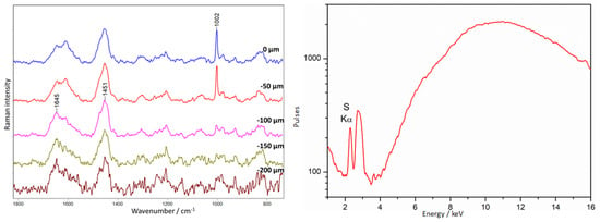
Figure 19.
Amber plaque. Example of an alkyd medium type of lacquer covering amber. Results of Raman (left) and XRF (right) measurements collected at point 34, according to Figure 3.
3.2.3. Other Colors in Fluorescence Images
This section presents examples of the presence of various “varnishes” on the surface of an object that exhibit markedly different fluorescence under UV light than amber. Three examples involve the observed dark violet color of fragments of amber objects. Unfortunately, it was possible in only one case to partially identify the substance used to coat the amber as a mixture with dibutyl phthalate. The last example discussed in this section is related to the observation of orange fluorescence attributed to shellac.
- Violet, i.e., fluorescence quenching
- Unknown I
The baroque crucifix shows very interesting physico-chemical characteristics. In visible light, one can see ambers of different shades placed according to the artist’s intention and forming a composition together. On the other hand, observation of the crucifix under UV radiation allows one to identify the places containing materials associated with previous conservation interventions. The most characteristic places are the legs, where only two out of six show the fluorescence characteristic of amber (Figure 11).
A depth profile was performed in this area (point 1, Figure 11), and the result is presented in Figure 20. At the surface level (0 µm), an intense spectrum different from that of amber is visible. Intense bands are observed at 1600, 1476, 1399, 1338, 1205, 1042, and 914 cm−1. Based on this, the constituent substance was identified as dibutyl or diethyl phthalate, as evidenced by bands at 1600, 1290, and 1043 cm−1 [40]. Distinguishing these two compounds is impossible based exclusively on the presence or absence of these bands. In addition, there are bands that could not be assigned to any substance: 1476, 1399, 1338, 1205, and 914 cm−1. The same substance covered the earwigs at the upper levels of the crucifix. From the −100 µm level, pure amber is observed.
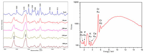
Figure 20.
Crucifix. Example of an unknown I type of lacquer covering amber. Results of Raman (left) and XRF (right) measurements collected at point 1, according to Figure 11.
XRF measurements in this area showed an unusually high concentration of chromium compounds for amber.
- 2.
- Unknown II
Surprisingly, the lower ledge of the crucifix (point 2, Figure 11) was coated with a different substance than the legs of the crucifix. Figure 21 shows the results of the depth analysis for this area.
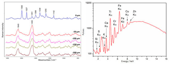
Figure 21.
Crucifix. Example of an unknown II type of lacquer covering amber. Results of Raman (left) and XRF (right) measurements were collected at point 2, according to Figure 11.
The varnish covering the ledge is characterized by an intense spectrum, despite the thin layer (from the −50 µm level, only pure amber is observed); the bands are very characteristic, and the amber spectrum is not observable in the first layer. Distinct bands are visible at 1595, 1527, 1451, 1399, 1339, 1255, and 1142 cm−1. Unfortunately, the substance could not be identified. Interestingly, in the form of an outer layer, it was identified on the object only here, while the column under the cross, which also has a purple color under UV radiation, was entirely filled with a secondary substance, containing the substance used to cover the cornice and mineral fillers.
Moreover, this area is characterized by the presence of titanium compounds, as evidenced by XRF measurements.
- 3.
- Unknown III
A dark violet color is also observed on the casket (point 19, Figure 9). Tests performed here showed that the amber was coated with an unknown substance with a spectrum characterized by bands at 1596, 1414, 1316, 1251, 1203, 1158, 1142, and 1002 cm−1 (Figure 22). The spectrum of amber without a varnish layer was recorded at a depth of −150–200 µm.
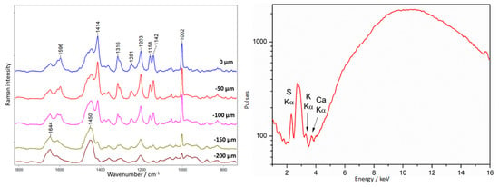
Figure 22.
Amber chest. Example of an unknown III type of lacquer covering amber. Results of Raman (left) and XRF (right) measurements collected at point 19, according to Figure 9.
XRF spectra showed only the presence of potassium sulfur and calcium, i.e., elements associated with the amber.
- Orange fluorescent shellac-type of varnish
A depth profiling study was also performed in the area of the observed orange fluorescence on the amber casket at point 24 (Figure 8), attributed to the presence of shellac. The spectrum recorded on the surface is very weak and noisy (Figure 23). Very weak bands appear at 1642 and 1452 cm−1. It is not possible to identify shellac from it, the spectrum of which is very similar to that of amber [64]. It is interesting to note that spectra collected from deeper layers show the characteristic amber bands at 1645 and 1450 cm−1.
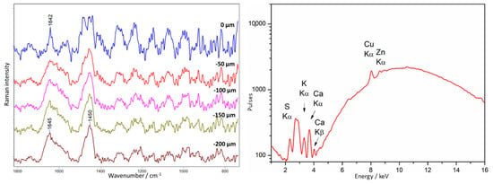
Figure 23.
Amber chest. Example of a shellac type of a varnish covering amber. Results of Raman (left) and XRF (right) measurements were collected at point 19, according to Figure 9.
XRF spectra in this area have shown the presence of the elements S, K, Ca, and traces of Cu and Zn, probably originating from the presence of a brass plate under the amber.
4. Conclusions
This study aimed to develop a methodology for detecting and analyzing protective coatings on amber objects, specifically focusing on those from the 17th and 18th century Gdansk workshops. The research employed a combination of macroscopic and microscopic techniques, including technical photography, RIS, Raman spectroscopy, and XRF.
Technical photography utilizes visible light and UV radiation. UV photography was particularly effective for identifying amber and locating areas containing materials associated with conservation interventions by revealing differences in fluorescence.
RIS allowed for the analysis of surface characteristics over large areas. It provided maps that indicated the location of amber and areas requiring further investigation, helping to identify synthetic resins and protective layers, although thin layers might not produce strong signals.
At the microscopic level, Raman spectroscopy performed depth profiling to observe changes in spectral profiles based on distance from the surface. RS was instrumental in identifying various substances used as protective coatings, including synthetic resins and nitrocellulose varnishes. Despite being sensitive to surface conditions, RS proved effective for identifying organic compounds.
XRF quickly identified inorganic compounds in protective coatings and fillings, detecting elements like sulfur, chromium, barium, and titanium. However, XRF was limited in that it could not detect organic compounds, making Raman spectroscopy a necessary complementary technique.
The results indicated the presence of various synthetic resins and nitrocellulose varnishes. Some areas revealed substances not identifiable through UV or RIS but detected via Raman spectroscopy. The study faced challenges, such as the difficulty in detecting thin protective layers using RIS due to limited signal penetration depth and non-characteristic fluorescence under UV light, which led to potential misidentifications. Additionally, amber degradation affected the spectral profiles, complicating the analysis.
The developed methodology proved effective in identifying and mapping conservation interventions. The combination of techniques allowed for a comprehensive analysis despite the limitations of individual methods. The study included case studies such as Maucher’s Casket, where a detailed analysis revealed high-quality craftsmanship and various conservation materials. Similarly, analyses of a chessboard and a crucifix showed differences in amber types and conservation substances used, identifying some synthetic resins.
Overall, the study provided a preliminary approach to amber conservation, utilizing a mix of techniques to overcome individual limitations and offering valuable insights into the materials and methods used in historical restorations.
Author Contributions
Conceptualization, A.R.; methodology, A.R., A.K.-K., P.K.-W., M.O., T.W. and M.M., validation, A.R., A.K.-K., P.K.-W., M.M., T.W. and M.O.; formal analysis, A.R., A.K.-K. and P.K.-W.; investigation, A.R., A.K.-K., P.K.-W., T.W., M.M., M.O., K.S., A.K. and J.M.d.H.-M.; writing—original draft preparation, A.R., A.K.-K. and P.K.-W.; writing—review and editing, A.R., A.K.-K., P.K.-W. and J.M.d.H.-M.; supervision, A.R. and J.M.d.H.-M. All authors have read and agreed to the published version of the manuscript.
Funding
This research was funded by the Polish Ministry of Culture and National Heritage, contract number: 155/DF-VII/2021, 231/DF-VII/2022, 21/DF-VII/2023.
Data Availability Statement
The raw data supporting the conclusions of this article will be made available by the authors on request.
Acknowledgments
We wish to thank Joanna Harasim-Grym (Museum of Gdańsk), Elżbieta Kuraś (National Museum in Krakow), and Jolanta Ratuszna (The Malbork Castle Museum) for valuable discussions about the results from the conservator’s point of view.
Conflicts of Interest
The authors declare no conflicts of interest.
References
- Kosmowska-Ceranowicz, B.; Sobecka, A.; Sontag, E. Bursztyn. In Złoża-Właściwości-Kolekcje; Miedzynarodowe Stowarzyszenie Bursztynników: Gdańsk, Poland, 2017. [Google Scholar]
- Penney, D. Biodiversity of Fossils in Amber from the Major World Deposits; Siri Scientific Press: Rochdale, UK, 2010. [Google Scholar]
- Beck, C.W. Authentication and conservation of amber: Conflict of interests. Stud. Conserv. 1982, 27, 104–107. [Google Scholar] [CrossRef]
- Thickett, D.; Cruickshank, P.; Ward, C. The Conservation of Amber. Stud. Conserv. 1995, 40, 217–226. [Google Scholar] [CrossRef]
- Pastorelli, G.; Shashoua, Y.; Richter, J. Surface yellowing and fragmentation as warning signs of depolymerisation in Baltic amber. Polym. Degrad. Stab. 2013, 98, 2317–2322. [Google Scholar] [CrossRef]
- Pastorelli, G.; Richter, J.; Shashoua, Y. Photoageing of Baltic amber e Influence of daylight radiation behind window glass on surface colour and chemistry. Polym. Degrad. Stab. 2011, 96, 1996–2001. [Google Scholar] [CrossRef]
- Clifford, D.J.; Hatcher, P.G. Structural transformations of polylabdanoid resinites during maturation. Org. Geochem. 1995, 23, 407–418. [Google Scholar] [CrossRef]
- Clifford, D.J.; Hatcher, P.G.; Botto, R.E.; Muntean, J.V.; Anderson, K.B. The nature and fate of natural resins in the geosphere. IX Structure and maturation similarities of soluble and insoluble polylabdanoids isolated from Tertiary Class I resinites. Org. Geochem. 1999, 30, 635–650. [Google Scholar] [CrossRef]
- Shashoua, Y.; Lund Degn Berthelsen, M.-B.; Faurskov Nielsen, O. Raman and ATR-FTIR spectroscopies applied to the conservation of archaeological Baltic amber. J. Raman Spectrosc. 2006, 37, 1221–1227. [Google Scholar] [CrossRef]
- Culture.pl. Available online: https://culture.pl/en/article/amber-poland-a-history-crafted-in-resin (accessed on 19 June 2024).
- Trusted, M. Catalogue of European Ambers in the Victoria and Albert Museum; Victoria and Albert Museum: London, UK, 1985. [Google Scholar]
- amber.com.pl. Available online: https://www.amber.com.pl/bursztyn/muzea-i-zbiory-bursztynu/122-szwecja/1528-zabytki-z-bursztynu-w-muzeach-szwedzkich (accessed on 19 June 2024).
- amber.com.pl. Available online: https://www.amber.com.pl/bursztyn/muzea-i-zbiory-bursztynu/119-niemcy/1523-bursztyn-w-muzeach-berlina (accessed on 19 June 2024).
- Grążawska, J. Modern era artefacts in the collection of the Amber Museum in Gdańsk. In Proceedings of the AMBERIF 2009 16th Seminar, Gdańsk/Warsaw, Poland, 14 March 2009; Kosmowska-Ceranowicz, B., Gierłowski, W., Eds.; The Gdańsk International Fair Co. (MTG SA), Gdańsk, The Museum of the Earth, Polish Academy of Sciences: Warsaw, Poland, 2009; pp. 25–35. [Google Scholar]
- Sobecka, A. Amber Treasures—An amber exhibition at Malbork Castle. Bursztynisko 2011, 33, 25–26. [Google Scholar]
- Sadowski, E.-M.; Schmidt, A.R.; Seyfullah, L.J.; Solórzano-Kraemer, M.M.; Neumann, C.; Perrichot, V.; Hamann, C.; Milke, R.; Nascimbene, P.C. Conservation, preparation and imaging of diverse ambers and their inclusions. Earth-Sci. Rev. 2021, 220, 103653. [Google Scholar] [CrossRef]
- Bisulca, C.; Nascimbene, P.C.; Elkin, L.; Grimaldi, D.A. Variation In the deterioration of fossil resins and implications for the conservation of fossil in Amber. Am. Mus. Novit. 2012, 3734, 1–19. [Google Scholar] [CrossRef]
- Beck, C.; Wilbur, E.; Méret, S.; Kossove, D.; Kermani, K. The infrared spectra of amber and the identification of Baltic amber. Archaeometry 1965, 8, 96–109. [Google Scholar] [CrossRef]
- Caldararo, N.; Hirschbein, J.; Palmer, P.; Shepard, H. The Analysis, identification and treatment of an amber artifact. Archeomatica 2013, 2, 46–49. [Google Scholar]
- Elora, E.; Kuhn, H.; Choi, M.; Wuellner, E.; Brody, L.R.; Frahm, E. Establishing the Baltic origins of archaeological amber beads from Dura-Europos (Syria) using non-destructive DRIFTS. J. Archaeol. Sci. Rep. 2023, 49, 103938. [Google Scholar]
- Angelini, I.; Bellintani, P. Archaeological ambers from northern Italy: An FTIR-DRIFT study of provenance by comparison with the geological amber database. Archaeometry 2005, 47, 441–454. [Google Scholar] [CrossRef]
- Teodor, E.D.; Liţescu, S.C.; Neacşu, A.; Truică, G.; Albu, C. Analytical methods to differentiate Romanian amber and Baltic amber, for archaeological applications. Cent. Eur. J. Chem. 2009, 7, 560–568. [Google Scholar] [CrossRef]
- Verkhovskaia, I. Baltic amber inspection: Micro-macro-structural and luminescent analysis. E3S Web Conf. 2019, 138, 01010. [Google Scholar] [CrossRef]
- Delaney, J.K.; Thoury, M.; Zeibel, J.G.; Ricciardi, P.; Morales, K.M.; Dooley, K.A. Visible and infrared imaging spectroscopy of paintings and improved reflectography. Herit. Sci. 2016, 4, 6. [Google Scholar] [CrossRef]
- Kleynhans, T.; Schmidt Patterson, C.M.; Dooley, K.A.; Messinger, D.W.; Delaney, J.K. An alternative approach to mapping pigments in paintings with hyperspectral reflectance image cubes using artificial intelligence. Herit. Sci. 2020, 8, 84. [Google Scholar] [CrossRef]
- Dooley, K.A.; Lomax, S.; Zeibel, J.G.; Miliani, C.; Ricciardi, P.; Hoenigswald, A.; Loew, M.; Delaney, J.K. Mapping od egg yolk and animal skin glue paint binders in Early Renaissance paintings using near infrared reflectance imaging spectroscopy. Analyst 2013, 138, 4838–4848. [Google Scholar] [CrossRef]
- Striova, J.; Dal Fovo, A.; Fontana, R. Reflectance imaging spectroscopy in heritage science. Riv. Nuovo C. 2020, 43, 515–566. [Google Scholar] [CrossRef]
- Alfeld, M.; Mulliez, M.; Devogelaere, J.; de Viguerie, L.; Jockey, P.; Walter, P. MA-XRF and hyperspectral reflectance imaging for visualizing traces of antique polychromy on the Frieze of the Siphnian Treasury. Microchem. J. 2018, 141, 395–403. [Google Scholar] [CrossRef]
- Cucci, C.; Delaney, J.K.; Picollo, M. Reflectance Hyperspectral Imaging for Investigation of Works of Art: Old Master Paintings and Illuminated Manuscripts. Acc. Chem. Res. 2016, 49, 2070–2079. [Google Scholar] [CrossRef]
- Gao, Z.; Du, M.; Ning, C.; Hou, M.; Wang, W.; Lyu, S. Application of hyperspectral imaging technology to digitally protect murals in the Qutan temple. Herit. Sci. 2023, 11, 8. [Google Scholar] [CrossRef]
- Garcia-Allende, P.B.; Conde, O.M.; Mirapeix, J.; Cobo, A.; Lopez-Higuera, J.M. Quality control of industrial processes by combining a hyperspectral sensor and Fisher’s linear discriminant analysis. Sens. Actuators B Chem. 2008, 129, 977–984. [Google Scholar] [CrossRef]
- Porebski, A.; Alimoussa, M.; Vandenbroucke, N. Comparison of color imaging vs. hyperspectral imaging for texture classification. Pattern Recognit. Lett. 2022, 161, 115–121. [Google Scholar] [CrossRef]
- Tamin, O.; Moung, E.G.; Dargham, J.A.; Yahya, F.; Omatu, S. A review of hyperspectral imaging-based plastic waste detection state-of-the-arts. Int. J. Electr. Comput. Eng. 2023, 13, 3407–3419. [Google Scholar] [CrossRef]
- Sun, D.-W.; Pu, H.; Yu, J. Application of hyperspectral imaging technology in the food industry. Nat. Rev. Electr. Eng. 2024, 1, 251–263. [Google Scholar] [CrossRef]
- Angelin, E.M.; Cucci, C.; Picollo, M. What about discoloration in plastic artifacts? The use of Fiber Optic Reflectance Spectroscopy in the scope of conservation. Heritage 2022, 14, 87–93. [Google Scholar]
- Orsili, J.; Caglio, S. Combined Scanned Macro X-Ray Fluorescence and Reflectance Spectroscopy Mapping on Corroded Ancient Bronzes. Minerals 2024, 14, 192. [Google Scholar] [CrossRef]
- Krupska-Wolas, P.; Rygula, A.; Kuraś, E.; del Hoyo-Meléndez, J. SWIR Reflectance Imaging Spectroscopy and Raman Spectroscopy Applied to the Investigation of Amber Heritage Objects: Case Study on the Amber Altar of the Lord’s Passion. In The Future of Heritage Science and Technologies; Furferi, R., Governi, L., Volpe, Y., Gherardini, F., Seymour, K., Eds.; Springer: Berlin/Heidelberg, Germany, 2023; pp. 401–416. [Google Scholar]
- Truică, G.; Ditaranto, N.; Caggiani, M.; Mangone, A.; Liţescu, S.; Teodor, E.; Sabbatini, L.; Radu, G. A multi-analytical approach to amber characterisation. Chem. Pap. 2014, 68, 15–21. [Google Scholar] [CrossRef]
- Klisińska-Kopacz, A.; Łydżba-Kopczyńska, B.; Czarnecka, M.; Koźlecki, T.; del Hoyo Mélendez, J.; Mendys, A.; Kłosowska-Klechowska, A.; Obarzanowski, M.; Frączek, P. Raman spectroscopy as a powerful technique for the identification of polymers used in cast sculptures from museum collections. J. Raman Spectrosc. 2018, 50, 213–221. [Google Scholar] [CrossRef]
- Paris, C.; Coupry, C. Fourier transform Raman spectroscopic study of the first cellulose-based artificial materials in heritage. J. Raman Spectrosc. 2005, 36, 77–82. [Google Scholar] [CrossRef]
- Madden, O.; Cullen Cobb, K.; Spencer, A.M. Raman spectroscopic characterization of laminated glass and transparent sheet plastics to amplify a history of early aviation ‘glass’. J. Raman Spectrosc. 2014, 45, 1215–1224. [Google Scholar] [CrossRef]
- Regel, B.M. The Conservation of Doped-Fabric Aircraft at the Science Museum. Ph.D. Thesis, Imperial College London, London, UK, 2019. [Google Scholar]
- Sobecka, A. A new interpretation of the mythological iconography of the Malbork Casket. In International Symposium “Amber. Science and Art” (Amberif 2018); Gdańsk International Fair Co.: Gdańsk, Poland, 2018; pp. 153–155. [Google Scholar]
- Grążawska, J. Vintage amber art from the collection of the amber museum in Gdańsk. In Baltic Amber–Treasure of the Bay of Gdańsk; Szadziewski, R., Pytlos, R., Szwedo, J., Eds.; Związek Miast i Gmin Morskich: Gdańsk, Poland, 2018; pp. 149–162. [Google Scholar]
- Sobecka, A. An amber Chess Set for the dukes of Atholl. Bursztynisko 2018, 42, 21. [Google Scholar]
- Klein, M.; Aalderink, B.; Padoan, R.; de Bruin, G.; Steemers, T. Quantitative hyperspectral reflectance imaging. Sensors 2008, 8, 5576–5618. [Google Scholar] [CrossRef]
- Lowe, D.G. Distinctive Image Features from Scale Invariant Keypoints. Int. J. Comput. Vis. 2004, 60, 91–110. [Google Scholar] [CrossRef]
- Rygula, A.; Klisińska-Kopacz, A.; Krupska, P.; Kuraś, E.; del Hoyo-Meléndez, J.M. The surface degradation of Baltic amber: The depth-profiling analysis and its application to historical object. J Raman Spectrosc. 2021, 52, 123–129. [Google Scholar] [CrossRef]
- Golloch, A.; Heidbreder, S.; Luhr, C. Identification of amber and imitations by near infrared reflection spectroscopy. Fresenius J. Anal. Chem. 1998, 361, 545–546. [Google Scholar] [CrossRef]
- Goddu, R.F. Near-Infrared Spectrophotometry. In Advances Analytical Chemistry and Instrumentation, 1st ed.; Reilley, C.N., Ed.; Interscience Publishers, Inc.: New York, NY, USA, 1960; Volume 1, pp. 347–424. [Google Scholar]
- Weyer, L.G.; Lo, S.-C. Spectra-Structure Correlations in the Near-infrared. In Handbook of Vibrational Spectroscopy; Chalmers, J.M., Griffiths, P.R., Eds.; John Wiley & Sons Ltd.: Chichester, UK, 2002; Volume 3, pp. 1817–1837. [Google Scholar]
- Workman, J. Handbook of Organic Compounds: NIR, IR, Raman, and UV-Vis Spectra Featuring Polymers and Surfactants; Academic Press: San Diego, CA, USA, 2000; pp. 77–197. [Google Scholar]
- Measday, D.; Walker, C.; Pemberton, B. A Summary of Ultra-Violet Fluorescent Materials Relevant to Conservation. AICCM Natl. Newsl. 2017, 137. Available online: https://aiccm.org.au/network-news/summary-ultra-violet-fluorescent-materials-relevant-conservation/ (accessed on 22 July 2024).
- Liu, Q.; Li, D.; Guan, C. Analysis of initiator content of prepreg by near-infrared spectroscopy. Rev. Anal. Chem. 2022, 41, 74–82. [Google Scholar] [CrossRef]
- Blanco, M.; Cruz, J.; Armengol, M. Control production of polyester resins by NIR spectroscopy. Microchem. J. 2008, 90, 118–123. [Google Scholar] [CrossRef]
- Miller, C.E.; Eichinger, B.E. Analysis of Rigid Polyurethane Foams by Near-Infrared Diffuse Reflectance Spectroscopy. Appl. Spectrosc. 1990, 44, 887–894. [Google Scholar] [CrossRef]
- Estupinan Mendez, D.; Allscher, T. Advantages of External Reflection and Transflection over ATR in the Rapid Material Characterization of Negatives and Films via FTIR Spectroscopy. Polymers 2022, 14, 808. [Google Scholar] [CrossRef] [PubMed]
- Edwards, H.G.M.; Farwell, D.W. Fourier transform-Raman spectroscopy of amber. Spectrochim. Acta Part A 1996, 52, 1119–1125. [Google Scholar] [CrossRef]
- Bakovic, M.; Karapandza, S.; Mcheik, S.; Pejovič-Milič, A. Scientific Study of the Origin of the Painting from the Early 20th Century Leads to Pablo Picasso. Heritage 2022, 5, 1120–1140. [Google Scholar] [CrossRef]
- Noake, E.; Lau, D.; Nel, P. Identification of cellulose nitrate based adhesive repairs in archaeological pottery of the University of Melbourne’s Middle Eastern archaeological pottery collection using portable FTIR-ATR spectroscopy and PCA. Herit. Sci. 2017, 5, 3. [Google Scholar] [CrossRef]
- Casanova, E.; Charlene, P.; Guilminot, E.; Mévellec, J.; Riquier-Bouclet, C.; Vinçotte, A.; Lemoine, G. The use of vibrational spectroscopy techniques as a tool for the discrimination and identification of the natural and synthetic organic compounds used in conservation. Anal. Methods 2016, 8, 8514–8527. [Google Scholar] [CrossRef]
- Pagnin, L. Characterization and quantification of modern painting materials by IR and Raman spectroscopies. Master’s Thesis, Università Ca’ Foscari Venezia, Venice, Italy, 2017. [Google Scholar]
- Selwitz, C.M. Cellulose Nitrate in Conservation; J. Paul Getty Trust: Los Angeles, CA, USA, 1988. [Google Scholar]
- Vandenabeele, P.; Wehling, B.; Moens, L.; Edwards, H.; De Reu, M.; Van Hooydonk, G. Analysis with micro-Raman spectroscopy of natural organic binding media and varnishes used in art. Anal. Chim. Acta 2000, 407, 261–274. [Google Scholar] [CrossRef]
Disclaimer/Publisher’s Note: The statements, opinions and data contained in all publications are solely those of the individual author(s) and contributor(s) and not of MDPI and/or the editor(s). MDPI and/or the editor(s) disclaim responsibility for any injury to people or property resulting from any ideas, methods, instructions or products referred to in the content. |
© 2024 by the authors. Licensee MDPI, Basel, Switzerland. This article is an open access article distributed under the terms and conditions of the Creative Commons Attribution (CC BY) license (https://creativecommons.org/licenses/by/4.0/).