1. Introduction
Heritage buildings are a vital legacy for future generations; however, these buildings are constantly threatened by natural and human-induced hazards, deterioration and ageing. Though the conservation and reuse of these buildings have gained momentum, the challenges are undeniable. A long-lasting lack of maintenance complicated by growing aggressiveness of environmental and operational conditions (e.g., climate change effects, increase in service load, etc.), recent budget cuts, financial crises and the need for sustainable use of resources call for cost-effective practices in built heritage management [
1,
2]. This shift in perspective from remedial and emergency interventions to proactive and preventive conservation is currently promoted by national and international policies and institutions such as the International Council for Monuments and Sites (ICOMOS) [
3].
Within this new vision, the conservation of historic buildings requires a thorough understanding of the building and its ambient specific needs, character-defining elements, structural systems, material properties, boundary conditions, vulnerabilities to the expected sources of hazards, current state and its anticipated evolution. Moreover, any activity carried out must comply with critical conservation principles, such as minimum intervention, compatibility, durability and reversibility. Thus, accurate inspection and diagnosis are necessary tasks, repeated over time, and experimental tests become indispensable, as they are the key for acquiring crucial input data for accurate structural assessments and monitoring. These are fundamental tools for the continuous analysis of the behaviour of the structure or the evaluation of interventions [
4].
Developing and implementing cost-effective conservation frameworks capable of addressing all the above-mentioned aspects is paramount. To this end, a holistic approach that integrates risk assessment and condition-monitoring strategies emerges as a promising solution to ensure an efficient and timely conservation of built heritage [
2,
5]. This approach involves systematically identifying and analysing potential risks to the integrity of the historical structure, establishing connections between causal factors, visible damage and anticipated consequences to forecast potential losses under expected hazard scenarios. Simultaneously, it incorporates continuous or periodic monitoring of the asset’s condition to detect, in almost real-time, any occurrence or evolution of the damage [
6]. This combination targets and prioritises the conservation efforts supporting proactive maintenance activities and optimised allocation of resources.
The effective integration of risk assessment with condition-monitoring strategies depends on the development of a robust model capable of acting as a dynamic counterpart to the real structure that evolves in parallel to it, reflecting its variations over time and allowing a forward-looking view of the evolution of its performance [
7]. This digital twin model concept can be grounded on the Building Information Modelling (BIM) methodology. After its promising applications for new buildings, this approach has gained an important role in the field of the preservation of heritage buildings, as the so-called Historical BIM (HBIM) [
8]. By employing HBIM principles, the digital twins of historic buildings not only capture their current state but also allow for simulations, predictive analysis and informed decisions on conservation, restoration and adaptation [
9,
10,
11]. This holistic approach facilitates a deeper understanding of historic structures, helps preserve cultural heritage and guides management practices towards a more sustainable and efficient path.
Within HBIM practice, the implementation of an appropriate workflow and methodology strongly depends on the identification of the model goals and anticipated uses. In particular, this drives the definition of the Level of Information Need [
12]. The Level of Information Need is not only about the graphic fidelity of the building elements, which encompasses factors such as geometry, scale and orientation [
13]. It also includes the non-graphical embedded data and the linked information (e.g., reports or images) associated with these elements, such as material properties, ongoing deterioration mechanisms, test results, historical data, etc. [
8]. A proper definition of this level aims at a cost-effective balance between highly detailed geometry and linked alphanumerical information and additional documentation [
14,
15,
16]. For instance, models intended to inform the design of interventions [
15,
17] may require more geometrical accuracy and resolution than those for supporting inspection and management tasks. Agents’ involvement is equally critical throughout the process. Indeed, the characteristics of the model must be agreed upon by all the parties, including those involved in data collection and model design as well as the end users. Simplification of the process is essential, especially as stakeholders may have little or no experience with BIM methodologies. To this end, delivering the model in an open access format eliminates the need for costly licences and ensures wide accessibility [
18]. The methodology for implementing new information and updating the model should be intuitive and simple. This facilitates the effective contribution of stakeholders, regardless of their level of BIM expertise. Standardised forms linked to the initial model can streamline data input and updates, simplifying the overall process. Developing an effective methodology for HBIM implementation is crucial to successfully manage and preserve historic structures. By defining clear objectives, involving stakeholders and applying easy-to-understand processes, the full potential of BIM in historic preservation can be realised [
19]. Although HBIM practices are increasingly used in heritage management [
11,
20,
21,
22], these often address specific tasks of the conservation, and an all-encompassing streamlined workflow that is replicable, standardised and user-friendly is still missing. Therefore, it is crucial to continue working on the adaptation of BIM to historic buildings and to make its applications available to experts.
The present paper aims to address this issue by testing and validating a streamlined workflow on a significative and complex historical building, namely, the church of Santa Ana in Seville, Spain.
This comprehensive workflow aims to include several tasks of built heritage conservation, including archive searches, geometric and damage surveys, material characterisation and vulnerability analysis using numerical simulation, providing a simple strategy to manage data collection, retrieval and sharing in a HBIM environment.
One of the main objectives of this application is to optimise the way information is collected and shown in the model, taking into account the specific BIM model goals and needs, to provide a solution that is able to maximise quality and accuracy based on the available resources, ensuring that under realistic operational, temporal and budgetary constraints, a sufficient level of knowledge can be generated to inform condition assessment and numerical structural analyses. Thus, this methodology is presented as an accessible tool regardless of the project’s size or the stakeholders’ experience and capacity. At the same time, it is flexible enough to integrate more advanced strategies for data collection and processing when the allocated resources allow it.
The investigated building presents complex architectural and constructive features and is representative of many of the religious buildings in southern Spain. Furthermore, it has suffered damage across its life due to different catastrophes, mainly earthquakes. The generated model constitutes the core of the envisaged digital twin of the heritage building, allowing a systematisation of the results of the ongoing research activities and encompassing historical data and documentary search, inspection, testing, diagnosis and structural assessment through numerical simulations.
The paper is organised as follows.
Section 2 explains in detail the methodology employed here.
Section 3 describes the case study, including the definition of the building, the results obtained from the historical survey and the description of the seismic area where it is located.
Section 4 includes the inspection, geometry survey, damage survey and in situ tests performed to characterise the building.
Section 5 describes the HBIM model and the strategy to integrate the collected information.
Section 6 contains the information about the structural model based on the HBIM model, the calibration and the results of the seismic analysis. Finally,
Section 7 describes the conclusions of the work and future scopes.
2. Methodology Proposal for HBIM Implementation
The methodology presented focuses on the definition of a model for the preventive conservation of heritage buildings. This model integrates information derived from historical studies and documentary search, geometrical survey based on photogrammetry or similar techniques, inspection and condition surveys, material characterisation and on-site tests. Moreover, it must outline a suitable accuracy of the geometry to establish a structural numerical model, essential to perform risk assessment [
23,
24].
Considering these objectives, the geometry definition should be sufficient to support preventive conservation, inform the structural model and cover all relevant constructive elements of the building. Normally, a very detailed geometry is not necessary for this purpose, which reduces the cost of this phase and allows for easier updating by operators with basic knowledge in the field [
25].
Thus, this methodology proposes a definition of a geometry based on the native elements offered by the BIM software whenever possible and creates specific elements only when necessary. To complement this information, the point cloud is incorporated into the model to contrast and consult detailed information on the geometry. The model also integrates alphanumeric information essential for the characterisation of each instance. To this end, a series of parameters are established that include historical information, material specifications and structural characteristics. The defined parameters are based on a proposal made within a previous project aiming at a standardised and replicable approach [
14].
In order to describe localised damage to specific architectural elements, a specialised model object is proposed. Similar approaches have been implemented in a BIM environment for various data storage and communication purposes, as in [
14,
16,
26]. Here, the definition of a cost-effective methodology is attempted by balancing clarity and complexity to foster its generalisation. The placeholder object is a parallelepiped linked to the affected element and located within the affected area that collects a series of features starting from the class of alteration according to the ICOMOS glossary stone deterioration patterns [
27] and the HeritageCare damage atlas [
28]. Additional alphanumeric information detailing the nature of the damage is stored, together with linked graphic information in the form of photographs or other graphic formats.
For damage affecting structural elements globally, a simplified approach is used. Damage descriptions are directly linked to the specific component, which provides a simple means of incorporating information related to structural deficiencies. This dual approach is adapted to the diverse nature of the alterations, offering a flexible but comprehensive methodology to capture and represent the state of conservation of the building.
To ensure a straightforward communication of the actual conditions to non-technical users, leveraging the navigable and visual nature of the model, damage maps created from orthophotos can be applied as superficial layers to the elements. This approach enhances the more detailed but schematic information provided by the damage-related objects and parameters with a graphical support for the stakeholders.
A similar solution is proposed to communicate the main results of on-site non-destructive testing, placing parallelepipeds on the analysed element within the specific area of the test. Standardised information regarding the type of test, its planning, execution and main results obtained are embedded in such objects. The results of the consecutive tests are stored in a data sheet associated with the object, assigning the last result to the parallelepiped. This approach not only streamlines the retrieval of previous test data but also lays the foundation for future comparative analysis, allowing for monitoring of structural integrity over time and an evaluation of the effectiveness of implemented remedial measures.
In case other graphical or alphanumerical information is available, this can be included in a similar way, defining standardised ad hoc objects with a simple geometrical shape linked to the information, for consulting during the navigation of the model. For example, when 360° views are available, a sphere located at the image capture point is used, containing the information of the 360° view [
16].
Once the information from the surveys is integrated into the BIM environment, a second phase of the process is proposed: the definition of a numerical model for structural assessment. This part of the methodology is crucial for a thorough risk assessment that requires simulating hazard scenarios and analysing the structural response to them. Therefore, the methodology envisages the definition of a finite element method (FEM) model to evaluate the non-linear behaviour of the structure under seismic action among other anticipated events. The model is used to assess the vulnerability of the structure and determines the need for interventions if mitigation measures against natural or human-induced hazards are considered necessary.
If dynamic information about the building is obtained during on-site testing, commonly through ambient vibration tests, the proposed methodology comprises the calibration of the aforementioned structural model. This calibration not only enhances the accuracy of the results obtained from seismic analysis but also provides a digital replica of the structural behaviour that can be further updated upon the acquisition of new information and/or as part of a continuous SHM (Structural Health Monitoring) system. This anticipated combination of the virtual replica in an HBIM environment and connectivity to the monitoring system and FEM simulations constitutes the digital twin of the building that can evolve over time together with the real counterpart [
7,
29].
This method is currently being applied to the church of Santa Ana in Seville, and its application is presented in the following sections to illustrate the methodology in detail. As of now, the implementation has progressed to the definition of the numerical model, including the calibration phase. Future work entails defining and implementing the monitoring system.
3. Santa Ana Church
The church of Santa Ana in Seville (Spain) is selected as the case study to support the validation and testing of the methodology envisaged in this paper. Its architectural and constructive features make this building a suitable and significant case study, being representative of many of the religious buildings in southern Spain, an area that presents a moderate seismic hazard and many heritage assets.
3.1. Historical Context
The historical context in which the church of Santa Ana was built is marked by the conquest of Seville by the troops of Fernando III of Castile in 1248. This led to a period of Christianisation in the city, in which the existing mosques were transformed into churches. Indeed, churches were organisms from which not only purely religious functions were exercised, but also different functions of social and territorial organisation. In parallel, another system was introduced, as the conquered territory was handed over to the nobility, the clergy and those who had helped the king, as well as to new settlers. Upon this initiative, the territory on the shore of the river opposite the main settlement of the city, known as Triana, began to grow in importance. Due to this growth, the existing church in this area became insufficient, and it was decided to build a new church, namely, Santa Ana church,
Figure 1.
Therefore, Santa Ana plays a rather important role in the history of Seville, being the first church built from the ground up without using an existing mosque as a base. Located outside the walls of the city, on the shore of the Guadalquivir River, it has a marked defensive character due to its position at the foot of the Aljarafe cornice, where constant attacks by the Muslims expelled from the city were taking place.
Alfonso X succeeded to the throne after Fernando III’s death. Under his reign, the construction of the primitive church began in 1266, according to the historian José Gestoso y Pérez, or in 1280, according to the historian Ortiz de Zúñiga [
30]. The complex was erected practically without interruption according to the planned layout, taking several years and at a slow pace due to the scarcity of resources. The building has peculiar characteristics due not only to its defensive nature but also to the combination of the Gothic style imported from Castilla and the Muslim Almohad style, which lasted even through the reconquest [
31]. This mix of styles is called Mudejar.
In addition, upon its original construction, the building has undergone numerous modifications and interventions over the years, so that its current state has not only Mudejar features but also Renaissance and Baroque ones. Several reasons for the interventions have been identified, including those carried out after natural catastrophes that damaged the building, such as floods, fires and mainly earthquakes, among which the earthquakes of 1356 and 1755 were particularly severe.
3.2. General Description
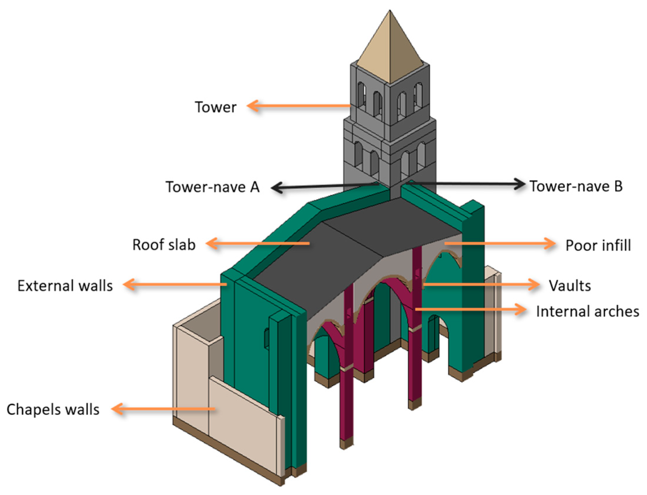
The church of Santa Ana is a rectangular building with three naves of five bays and one apse, namely, the Gospel nave on the left, the main nave in the centre and the Epistle nave on the right. The central nave is larger both in plan and height. However, the height of the side naves is very similar to the central one, because the roof is accessible through the tower due to its defensive nature. Therefore, the roof presents minimal slope, and its finishing layer is made of solid bricks (
Figure 2).
Despite the imperfections that occurred during construction, it can be seen that the columns are arranged according to a regular grid. The dimension of the church is about 44
varas long.
Vara was a common unit of measurement, known first as the
vara burgalesa and later as the
vara castellana and corresponding to 83.59 cm. Therefore, the approximate length of the naves is about 37 m. The columns of the naves support pointed arches that separate the naves. A gallery is located within the walls above the arches, and between these and the lateral walls are the ribbed vaults that cover the naves,
Figure 3. There is no information on the filling of these vaults, so it is estimated that there is a structural infill up to half of the vault, and that the remaining space is filled with poor material. The passable roof on top of this poor infill was intervened in one of the last renovations, when a concrete slab was created; however, detailed information about it was not found.
There are three entrances to the church, namely, a central portal on the main façade and one portal on each side, giving access to the lateral naves. The tower is attached to the left side of the façade and was probably crenellated at the top, given the defensive nature of the building.
The crypt is located under the Epistle nave and accessed through the Calvary Chapel. This is a longitudinal space covered by a barrel vault with a pointed arch that occupies almost the entire surface of the nave. Under the Gospel nave, there is access through a hole in the floor to a space also covered by a barrel vault.
At the time of the construction of the church of Santa Ana, stones were scarce in the area of Seville and very expensive. Therefore, masonry was commonly made of bricks. Indeed, most of Santa Ana is made of bricks, reserving the use of stone for the ribs of the vaults, arches, small columns, doorways and for those areas where greater strength was required, such as in the connection of the chancel with the body of the naves and the lower level of the tower. The stone blocks are made of calcarenite rock, likely from the Sierra de San Cristóbal [
32]. Mortar is lime-based and arranged in joints of considerable thickness, except for the stone vaults and the ribs, where thinner joints are present.
3.3. Evolution and Modifications over Time
From the construction of the original church to the present day, the geometry has undergone several alterations. The original plan consisted of a body with three naves of five bays and the apse, as shown in
Figure 4a. In the middle of the 14th century, the construction of the first part of the tower began. In 1499, the Calvary Chapel was built, occupying the apse of the Epistle nave.
Around 1505, the Capitan Monte Bernardo Chapel was annexed to the Gospel nave in the fourth bay next to the portal. In 1507, opposite the Chapel of Captain Monte Bernardo, the Chapel of Santa Bárbara was annexed to the Epistle nave. In the middle of the 16th century, the Sacramental Chapel was built in the second section of the Gospel nave,
Figure 4b.
In 1570, the Chapel of San Francisco was finished, partially occupying the last section of the Gospel nave. Symmetrically, in 1591, the Chapel of the Souls was built partially occupying the bay of the Epistle nave. At the end of the 16th century, the Chapel of San Joaquín was constructed in the second bay of the Epistle nave. Between 1614 and 1617, the Baptismal Chapel was built, next to the Chapel of Captain Monte Bernardo. In 1629, the construction of the second section of the tower and the pyramidal spire was carried out. Around 1865, the Chapel of the Divina Pastora was built in the last section of the Epistle nave. This configuration is shown in
Figure 4c. From 1993 onwards, works were carried out in the Sacristy courtyard [
33].
3.4. Seismic Hazard
Taking into account the information collected from past earthquakes and the geological characteristics, the Spanish territory is divided into five seismic areas, as shown in the seismic hazard map (
Figure 5). The Spanish seismic norm [
34,
35] defines the peak ground acceleration value for Seville as 0.09 g.
Although the seismic hazard of the area where the church is located is not one of the highest, Seville has historically suffered at least five major earthquakes, causing significant structural damage to the building stock, including Santa Ana church [
30,
36], as summarised in
Table 1.
4. Inspection
A detailed inspection of the church of Santa Ana was carried out, aiming at a geometrical survey, structural system inspection, material characterisation, dynamic identification and damage mapping to support the following structural assessment and diagnosis. Activities conducted on site are hereafter discussed.
4.1. Geometrical Survey
Photogrammetry is the geometric data acquisition technique used for this application. This technique stands out for its accessibility; the technique requires minimal equipment and expertise and delivers high-resolution models [
8,
37].
A photogrammetric survey of the church was carried out, and a 3D model of the exterior and interior was generated through Agisoft Metashape 1.8.4. software [
38]. A Sony ILCE-6000 digital camera with 42 MP was used for the collection of images. The photos were acquired with a fixed focal length of 16 mm. The model of the external part is based on 459 photos taken from the streets around the church,
Figure 6. Due to the unavailability of a drone, the roof has not been included in the model. Reference measurements taken in situ were used to scale the model. Several representative points were considered, including different sections, angles and directions. The final model was validated based on these measurements. The ground sampling distance (GSD) value is 2.19 mm/pix for this model.
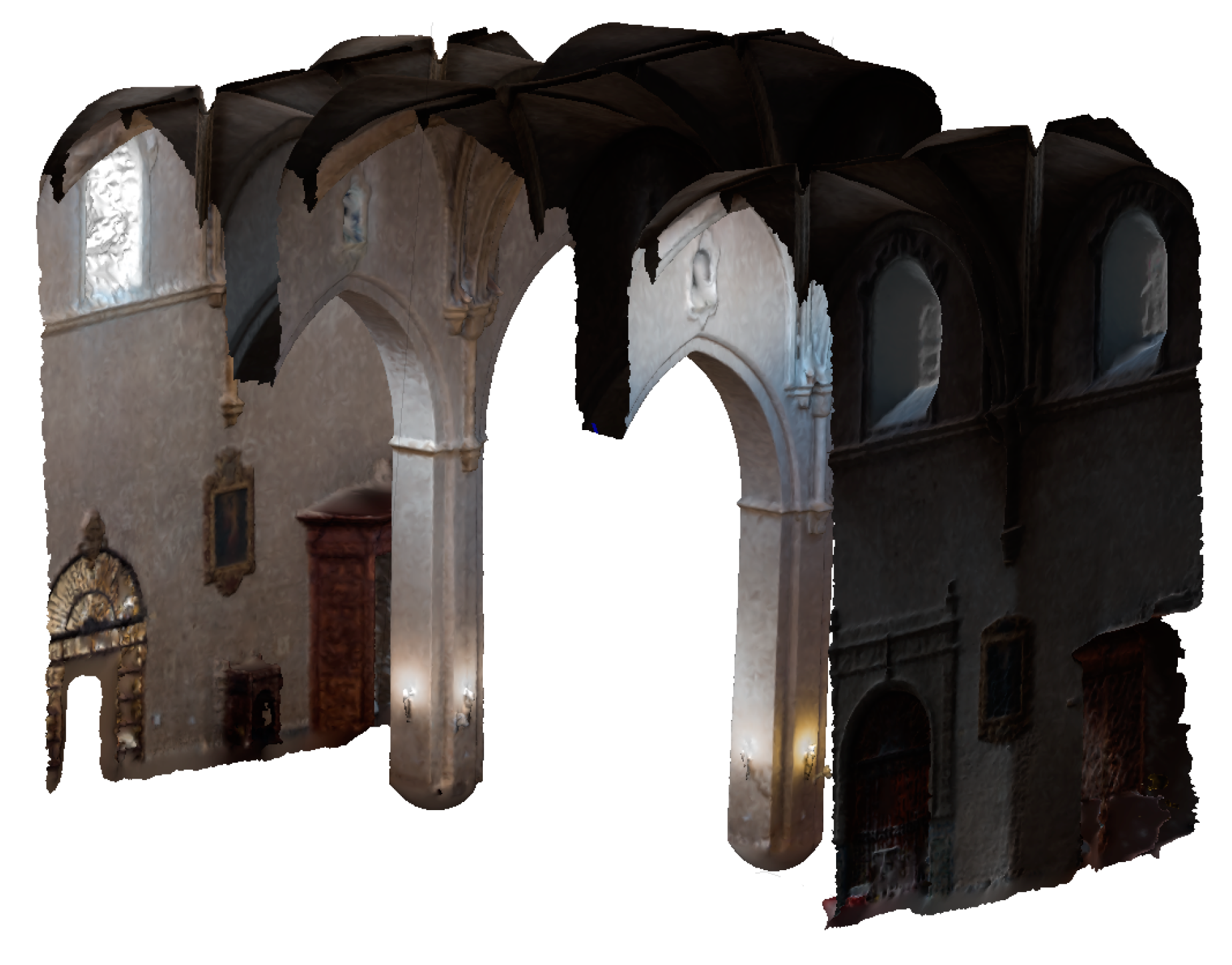
For the interior model, the same equipment and methodology was used. This model, composed of more than 280 photos, presented higher complexity due to the geometry and the details of the architectural decorations, the spatial configuration and all the artistic elements and furniture. Furthermore, problems related to non-optimal lighting conditions inside the church were addressed. In this case, the obtained GSD value is 2.39 mm/pix. A horizontal section of the model linking external and internal geometry is shown in
Figure 7.
A more refined model of the transversal arches that connect the third and fourth bays from the façade was generated for structural analysis and condition assessment purposes. This allowed for the obtainment of a more detailed geometry of the vaults and identification of the deformation of columns and arches (
Figure 8).
From the exterior model, a dense point cloud of 203 million points is obtained, and for the interior model, the point cloud obtained has more than 250 million points. The different meshes generated based on the dense point cloud were used to update the AutoCAD drawings (2D information). MeshLab 2023.12 software [
39] was used to process the mesh obtained from Agisoft Metashape for this purpose. The photogrammetric model was also used to obtain orthographic photos of the interior and exterior of the building, which were used as the base for the damage mapping and as a texture for the HBIM model.
Figure 9 shows an example of the orthographic photos of the vaults.
Moreover, 360° views were generated using a dedicated software program, PanoramaStudio [
40], merging overlapping photographs taken with a high-quality regular camera. This was the same model as that utilized for the photogrammetric model. The generation of high-quality 360° images allows for the visualisation of numerous details and serves as a support for damage analysis. A total of eight panoramic views were created; one example is shown in
Figure 10. The software used for the connection of the 360° views to create the virtual tour is PanoV2 [
41].
As demonstrated in previous experiences of the authors [
42], this navigable model is an extremely user-friendly tool to store and query multidisciplinary information from several different sources. The virtual tour can be visualised by any stakeholder using free-of-licence viewers either online or offline. In this case, the model was used as a support tool for the damage survey, as the information collected with hundreds of photos can be easily consulted in a single model.
4.2. Material Characterisation
The structural elements of the church are made of brick and stone. The typical brick used in the construction of the church is solid rustic brick, with approximate dimensions of 28–29 × 13 × 4–5 cm3. The brickwork is apparently uniform, featuring about 12–13 courses of bricks per metre for the vertical elements, horizontal joints of about 4 cm and slightly smaller vertical joints. On the other hand, the brickwork of the vaults of the naves is laid in a herringbone pattern. The stone is a limestone, with highly variable silica levels, coarse-grained and with high and uniform porosity.
Analysing the main features of the masonry, on site, three different typologies were recognised, and representative samples of each one were considered for the material characterisation through visual inspection and non-destructive testing (
Figure 11). One typology was consistently adopted for the vertical elements: columns and walls (
Figure 11a). A second one was identified in the vaults of the naves (
Figure 11b). Finally, a third typology that combines bricks and regular stones was used in the vaults of the altars (
Figure 11c).
A visual characterisation of the mechanical properties was carried out through a well-established methodology, namely, the Masonry Quality Index (MQI) [
42,
43]. The MQI method requires the evaluation of the fulfilment, partial fulfilment or non-fulfilment of seven parameters that, once combined, ensure a qualitative assessment of the masonry performance under vertical and horizontal loads. Indeed, different MQI values are obtained based on the loading directions, considering vertical (MQI
V), horizontal out-of-plane (MQI
O) and horizontal in-plane loads (MQI
I). The parameters are the conservation state and mechanical properties of the units, unit dimensions, unit shape, wall leaf connections, horizontal bedding characterisation, vertical joint characterisation and mortar mechanical properties. A quantitative material characterisation through the MQI is also viable, as the index is correlated with the mechanical properties of the historical masonry typologies defined in the Italian code [
44]. The MQI values for the three identified masonry categories are reported in
Table 2, and the values of the correlated material properties are reported in
Table 3.
After the initial attempt to define the properties of the materials by visual inspection, twelve sonic tests were carried out at different points in the building to obtain more specific information. Tests were conducted according to both the direct transmission arrangement, placing the transducers on opposite faces of the element, and the indirect transmission arrangement, placing the transducers onto the same face. Eight indirect tests were conducted on the walls, six in the brick masonry and two in the stone masonry close to the main altar. In the columns, two indirect and two direct tests were performed. The equipment used was composed of the acquisition system dewesoft SIRIUS 8xACC, one KS903B.100 triaxial accelerometer (MMF, Radebeul, Germany) (0.15 to 12,000 Hz bandwidth, 0.1 V/g sensitivity) and an IH-02 impact hammer (DJB Instruments (UK) Ltd., Suffolk, UK) (2000 N measuring range and 2.5 mV/N sensitivity).
The results are plotted in
Table 4, where the difference between the two points measured in each longitudinal wall (wall 1 and wall 2) can be observed. The masonry brick close to the main portal presents higher values than the other wall, around 2 GPa. The values for the stone masonry are around 1 GPa higher than those values, reaching values above 3 GPa. Finally, it can be observed how the direct and indirect tests performed in the columns provide different values, being lower for the indirect test, for which the values are closer to the ones obtained for the wall brick masonry elements.
4.3. Damage Survey
From the visual inspection, it was possible to establish the overall good condition of the church, despite the presence of alteration and deterioration phenomena, such as cracks, deformations and moisture stains, related to water infiltration.
In particular, two main systems of cracks affect the church. One is located in the lateral wall of the Epistle nave, in the second bay from the main façade (
Figure 12a). This crack reaches the top of the wall, continuing on the roof. The second one is located in the interior of the main façade (
Figure 12b). In this case, the cracks go from the top of the wall to the corner of the main portal, passing through the oculus and following the shape of the arch embedded in the wall.
Other less relevant cracks are present in the church, mostly on the lateral walls. Among them, it is worth mentioning a diagonal crack located in the window of the first module of the Gospel nave (
Figure 12c). The connections between the lateral walls and the apses also present vertical cracks. In the main altar, two cracks are located in the upper part.
A detailed mapping of the forms of deterioration, classified based on their type and characteristics, was superimposed on the orthophotos of the vertical elements as well as the vault system obtained from the photogrammetric model of the church. As an example,
Figure 13 shows the damage to the interior face of the wall of the Epistle nave.
Apart from cracks, most of the alterations consist of moisture stains, especially visible at the intrados of the vaults of the naves.
Figure 14 shows the damage map, including moisture stains and cracks affecting these elements. Moisture stains are mostly concentrated in the Gospel nave and the central bay close to the main façade, being mainly caused by the infiltration of water through the roof. This damage at the intrados coincides instead with the damage documented at the extrados of the roof, especially significant crack patterns affecting the brick joints. Due to the impossibility of including this area in the photogrammetric model, roof damage was mapped on 2D drawings and photos.
The detailed photogrammetric model of the third and fourth bays was further analysed to determine the current deformation of the vertical elements, in particular the columns that delimit the central nave.
Figure 15 shows a transversal section of the model. Deformations are around 13 cm at the top of the columns.
4.4. Dynamic Identification Tests
An ambient vibration test for the operational modal analysis of the church was conducted in September 2022. A total of 35 measurement points were instrumented, as shown in
Figure 16. The points are located on the roof of the naves and apse and on two levels of the tower (+15.4 and +20.5 m). Two points were also measured in the galleries of the longitudinal arcades (+12 m). Five force balance triaxial accelerometers (KINEMETRICS ES-T, Pasadena, CA, USA, 0.01 to 200 Hz bandwidth, 155 dB dynamic range, 10 V/g sensitivity) were used in nine consecutive setups, maintaining one accelerometer as a reference (black dot in
Figure 16) and roving the others along the church.
The accelerometers were connected to a 36-channel data acquisition system with an analogue-to-digital converter (Obsidiana 36× model). For each acquisition, a sampling rate of 50 Hz and a duration of 20 min were set.
The data obtained in situ were processed with ARTeMIS Modal 7.0 software [
45] using a well-established estimator: the Enhanced Frequency Domain Decomposition (EFDD). For a clearer insight into the dynamic behaviour of the building, two models were defined. One aimed at the global analysis of the structure, including all the measurement points except the two located in the galleries of the longitudinal arcades. The results of the first model are shown in
Figure 17. In particular, six modes were identified. The first two are local modes of vibration of the tower. The third is a transversal bending mode of the nave that also involves the tower in counterphase. The fourth is longitudinal, whereas the fifth is torsional. Finally, a local vertical mode of the roof is the sixth identified.
The second model aimed at the analysis of a single transversal section, thus including a total of seven measurement points, comprising setup 07 and some sensors from setup 09. The results of this second model are shown in
Figure 18. Except for the first mode of the tower, the remaining five modes are identified in the second model as well, with similar frequency values.
5. HBIM Model
The virtual replica in the HBIM environment was developed, aiming at a seamless integration of the information collected during the ongoing investigation, including upon future expansion of knowledge, through graphical and non-graphical modelled data. This specific case study employs Revit 2024 recasoftware [
46] for this purpose. However, the adopted methodology is independent of the specific software utilised.
The first step of the methodology aims to model the geometry of the structure based on existing drawings and on-site measurements, supplemented with the extensive point cloud information derived from the photogrammetric model. This point cloud, processed with Autodesk ReCap 2024 software [
47] and subsequently exported to a Revit-compatible format, served as a fundamental reference for the modelling process, especially for the more complex shapes such as the nave vaults and altar vaults.
In the delineation of the architectural elements, native parametric families were mainly used, which covered a spectrum of components such as walls, columns, floor slabs and roof systems. This simplifies the process and saves time; however, the complex nature of the building architecture necessitated the development of custom families tailored to the peculiar features of some of the components, such as the intricate vaults, as shown in
Figure 19.
As mentioned above, the level of geometric detail of the model was defined in order to ensure a representation of the correct dimensions of the building as well as the structural components, simplifying their details whenever possible and neglecting the decorative and artistic elements. To incorporate the information discussed in
Section 3 on the analysis of the alignment of the elements with the theoretical horizontal and vertical planes, the point cloud is kept linked to the model to be queried and navigated whenever needed,
Figure 20.
As mentioned in the definition of the methodology, the damage information obtained from the survey was incorporated into the model in three different ways, as visual damage maps applied as superficial layers and as information either included in the element when global or embedded in ad hoc object when localised. In what concerns the damage maps, high-resolution orthophotos have been attached to the interior perimeter walls and the arcades. Regarding the localised damage, specific objects have been created for the two main types of damage present in the church, cracks and moisture stains.
The parallelepipeds for the on-site non-destructive testing have been placed in the area where the test was performed. The placeholders for the sonic test include the information presented in
Table 4. Similarly, the location of the accelerometers during the dynamic tests was reported by introducing an object including the specification of the sensor, the number assigned and the setup in which they were recorded, as well as the results of the test.
In addition, the model incorporates useful 360° views that enrich the HBIM model with immersive visual data. For this purpose, a third object was defined, a sphere located at the image capture point.
Figure 21 shows the implementation of these elements in the model.
6. Numerical Model
For the structural analysis of the building, DIANA FEA [
48] has been chosen. First, a high-fidelity model is generated and used for condition monitoring,
Figure 22a. This model represents the actual dynamic behaviour of the structure under low vibration actions, serving as a reliable basis for an envisaged automatic damage identification strategy coupled with a continuous monitoring system. In this context, the focus is on the monitoring of the modal properties of the building under ambient excitation (OMA). To this end, a model is built and updated based on the modal identification campaign data.
Then, a second model is defined to investigate the seismic vulnerability of the church,
Figure 22b. The assumptions considered in this model differ from the previous one, as the goal is to analyse the behaviour under a larger amplitude of vibrations caused by an earthquake. This is expected to induce moderate–severe damage and, in general, a non-linear response of the structure significantly different from the one caused by environmental excitations (linear behaviour and very low amplitude of the actions). For the definition of this second model, some simplifications are made, namely, the infill and the concrete deck slab are included in the model as mass (equivalent density in the vaults and the longitudinal walls), without geometric and stiffness representation, due to the lack of information on the constructive details and the quality of connection with the side walls.
Modelling the infill and the concrete deck slab as physical objects can result in a significant increase in the stiffness when assuming medium/good material properties and connections to the side walls, leading to a box behaviour that increases the structural strength and likely overestimates the structure capacity. On the other hand, the low material properties of the infill and weak connections to the side walls cause excessive damage under self-weight only, unobserved in the real structure, which prevents a correct execution of the non-linear analysis.
6.1. Calibration of the High-Fidelity Model
The high-fidelity model geometry was defined based on the data included in the HBIM. Then, the modal properties obtained from the dynamic identification test were used for calibration, by updating the values of a set of variables in order to match numerical and experimental response [
49,
50]. To this end, a preliminary sensitivity analysis of the influence of the variables on the numerical estimation of the dynamic properties was carried out. From the initial fourteen variables considered, a final set of nine properties was considered for the calibration,
Figure 23.
Table 5 shows the final updated values. It is worth noting that the degree of connection between the tower and the nave is included, since a rigid connection failed at reproducing the dynamic behaviour of the tower as identified in the experimental test, especially for the shape of the local modes, first and second, and the counterphase vibration of the tower and the nave in the third mode.
The closeness between numerically predicted modal properties and experimental results is qualitatively demonstrated through the comparison of the shapes, mainly in the first four modes, plotted in
Figure 24. Moreover, it is assessed both in terms of relative error of the natural frequencies and modal assurance criterion (MAC), as reported in
Table 6. The connection between the tower and the nave governs the behaviour in the first two modes. The third mode is sensitive to the connection with the tower but also to the masonry properties of the vertical elements, as are modes four and five. The slab and the infill mechanical properties play a relevant role in mode six, having some influence in the third mode too.
6.2. Seismic Analysis
The seismic vulnerability assessment was carried out on the second, simplified model by means of non-linear static analysis [
51]. The material model used is a rotating total strain-based crack model, with exponential softening in tension and parabolic in compression. The capacity curves for the four main load distributions (i.e., positive and negative longitudinal X direction and positive and negative transversal Y direction) are plotted in
Figure 25. They show horizontal acceleration plotted against the displacement of a defined control point, in this case, the point with maximum displacement for each case [
52].
Santa Ana church presents a higher capacity in the longitudinal (X) than in the transversal (Y) direction. Moreover, in the case of the X direction, the maximum displacement is at the top of the tower, whereas in the Y direction, the maximum displacement is placed at the top of the central column of the arcades that divides the central and the lateral naves. For the +Y case, the maximum displacement is located in the arcade between the central and the Gospel nave (left), and in the −Y case, it is in the arcade between the central and the Epistle nave (right).
The damage pattern is presented in
Figure 26. Analysing the tensile principal strains for +X, the case with the higher capacity load (almost 0.3 g), it is possible to observe the rotation of the tower with a concentration of strains at the base and in the façade, close to the tower. The lateral vaults present shear diagonal cracks, typical for these elements bounded by a central nave with lower stiffness than the external walls.
This pattern is also present in −X. However, in this case, the capacity curve shows a lower value, and the damage reached in the longitudinal walls is higher than in the opposite direction. In both cases, cracks in the perpendicular connections between walls are also present.
In the transversal direction, the load capacity decreases by more than half (0.12 g). The damage is lower in the +Y direction due to the stiffness provided by the chapels on this side. Conversely, in the opposite orientation, the chapels have a smaller area, closing the space between buttresses with thin walls and without additional walls perpendicular to the façade. The damage pattern here shows cracks in the lateral façades indicating out-of-plane failure and a longitudinal crack at the top of the lateral vault close to that wall. However, the main problem is the collapse mechanism occurring at the points with maximum displacement, as mentioned before, particularly at the top of the central column of the arcades.
7. Conclusions
This article underlines the critical importance of heritage conservation and positions HBIM as a fundamental tool to achieve this goal. It presents a comprehensive methodology for the application of HBIM in historic buildings, covering HBIM model definition, structural analysis and associated processes. This methodology is exemplified by a detailed case study, namely, the church of Santa Ana in Seville (Spain), which integrates results from historical document search, visual inspection and damage mapping, a geometric survey based on photogrammetry, material characterisation and the creation of a virtual tour with 360° views. All these sources of information are used to enrich the BIM model.
The article concludes with the definition of two numerical models, each serving a specific purpose. Firstly, a highly accurate model that represents the actual dynamic behaviour of the structure under low ambient vibration is described. This model is calibrated with the data obtained from the OMA campaign, with the objective of being used for condition-monitoring purposes. The second model aims to study the seismic vulnerability of the church. For this purpose, some simplifications are made to balance reliability and computational costs.
In terms of geometric data acquisition, photogrammetry proved to be a convenient and cost-effective tool, despite its limitations in capturing information from higher areas, since the implementation of a drone survey was not feasible. Nonetheless, existing drawings and traditional in situ measurements supplemented the photogrammetry data sufficiently, providing the necessary detail to define the 3D model required for the study.
Upon inspection and diagnosis, some alterations in concern were identified, such as moisture stains on the intrados of the vaults, likely caused by roof infiltration and linked to the existing damage in the roof, especially cracks, which were documented during the visual inspection. Additionally, two main systems of cracks were identified: one in the lateral wall of the Epistle nave and another in the interior of the main façade. Though minor cracks are also present, those that have been repaired and reopened are of greater concern. Consequently, it is recommended to monitor these cracks closely and investigate their causes, analysing the soil and foundation of the building as well. To address the infiltration issue, assessing the continuity in the infill and ensuring the waterproofing of the roof is advised.
The creation of the HBIM model, despite requiring time and expertise due to its complexity and the volume of information to be managed, resulted in a comprehensive solution to integrate and communicate all the collected data and evidence. To enhance the methodology employed here, the deployment of a monitoring system seamlessly connected to the model is envisaged. This should comprise accelerometers for dynamic identification, tiltmeters in columns and walls with significant deviation from the vertical plane and crackmeters in main and reopened cracks.
The pushover analysis allowed us to conclude that the transverse direction of the Santa Ana church is the most vulnerable one (0.12 g), and the most vulnerable elements are the vaults and the connections between the columns and the arcades.


