Article

Historic Building Information Modeling for Conservation and Maintenance: San Niccolo’s Tower Gate, Florence

by
Anna Livia Ciuffreda
1,
Francesco Trovatelli
2,
Francesca Meli
2,
Giorgio Caselli
1,
Costanza Stramaccioni
1,
Massimo Coli
3 and
Marco Tanganelli
2,*
1
Servizio Belle Arti e Fabbrica di Palazzo Vecchio, Comune di Firenze, Via Giotto n° 4, 50121 Firenze, Italy
2
Dipartimento di Architettura (DiDA), Università Degli Studi di Firenze, Piazza Brunelleschi n° 6, 50121 Firenze, Italy
3
Dipartimento di Scienze Della Terra (DST), Università Degli Studi di Firenze, Via La Pira n° 4, 50121 Firenze, Italy
*
Author to whom correspondence should be addressed.
Heritage 2024, 7(3), 1334-1356; https://doi.org/10.3390/heritage7030064
Submission received: 30 January 2024 / Revised: 4 March 2024 / Accepted: 6 March 2024 / Published: 8 March 2024
(This article belongs to the Special Issue Architectural Heritage Management in Earthquake-Prone Areas)

Abstract

:
In the field of conservation and protection of heritage buildings, knowledge plays a fundamental role, emphasized by national and international rules and regulations. This aspect becomes fundamental when conducting the structural assessment of a historical building. This study envisaged a cognitive phase via the application of advanced survey and diagnostic methodologies to define the materials, construction techniques, and state of conservation of the structural system of a specific building forming part of Florence’s heritage. The information complex produced formed the basis for the structural assessment and for the experimentation of the BIM methodology within the creation of databases for the management of cognitive processes of historical buildings. The case study is one of the gates of the last circle of walls of the 14th century and is the only one that has maintained its original height, despite modifications: the gate/tower of San Niccolò. The research conducted, in addition to achieving a structural assessment of the tower, has allowed the creation of a dynamic model for organizing and consulting the information, laying the groundwork for the creation of a conservation and maintenance plan.

1. Introduction

The cognitive approach in the context of restoration and consolidation interventions on historic buildings has been studied and analyzed by the international scientific community for some decades now.
According to “Guidelines for the evaluation and reduction of seismic risk of cultural heritage”, published by MIBACT in 2011 [1], it is necessary to understand the state of conservation and functioning of the structural system of a building, as well as the causes of ongoing degradation and disruption. The knowledge acquired serves as the foundation for design choices. Therefore, a thorough understanding of cultural heritage is crucial as it allows for the inclusion of less invasive and more compatible approaches during the design phase.
In recent years, advancements in the diagnostic techniques applicable to cultural heritage have made it possible to develop increasingly extensive and complex investigation plans. Consequently, the proliferation of these studies has resulted in a significant increase in the volume and complexity of data. This has made interpretation more intricate and complex. Moreover, the accurate interpretation of diagnostic investigation results cannot be separated from the context in which they were conducted. These factors have prompted researchers to seek out methodologies for managing cognitive pathway data and tools that aid in the interpretation phase.
In this context, the use of building information modeling (BIM) for historical masonry buildings, known as historic building information modeling (HBIM) [2,3], has become prominent [4,5,6]. Currently, HBIM workflows primarily focus on documenting buildings’ current states. In these cases, the information model serves as a centralized database for managing input data and reading information [7,8,9]. Contributions that conduct review of the literature regarding current implementation of HBIM reveal that information management [10] is the most cited research topic, although the lack of a defined standard methodology persists [11].
This demonstrates the need for a standardized approach to information management in HBIM. Studies on scan-to-BIM input flows [12] attempt to automate the transition from point cloud to parametrized objects. This can be achieved using visual programming language (VPL) to improve the geometric and informational enrichment of the models [13]. The theme of integration and interoperability between information models explores the possibilities of making FEM numerical models and architectural models communicate inside or outside the BIM environment, combining different types of software and reducing data loss [14,15,16,17]. Structural vulnerability assessment is often accompanied by an integrated survey that uses various technologies to increase the efficiency and accuracy in detection and modelling, thereby improving the quality of the analysis [18,19,20].
The presented research project involved application of the cognitive process to a case study represented by one of the best-known and best-preserved gates of the last city wall of Florence: the gate/tower of San Niccolò. The study aimed to assess the state of conservation of materials and structures for the safety assessment against seismic action and to define ongoing restoration interventions. For this purpose, the building underwent an extensive diagnostic campaign to achieve the evaluation levels presented in [1] (LV1, LV2 and LV3).
The management of a voluminous and heterogeneous knowledge framework requires a tool capable of combining three-dimensional digital representations and complex databases. This process is defined as “parametric-informative”. This methodology, which has been successfully applied in other case studies of Florentine heritage [21], allows for the precise and efficient organization and consultation of information collected during study and investigation phases.

2. The BIM Methodology for the Knowledge Process of the Cultural Heritage

The methodology utilizes a three-dimensional representation of a building that, even schematic, contains geometric and morphological information. The information can include descriptive content relating to materials, technical characteristics, and more. Such content, if managed via parameters, gives rise to parametric information systems, which today are defined by the acronym BIM.
The use of BIM approach has made it possible to manage complex information flows, which can be effective in monitoring and preserving architectural heritage.
The building’s three-dimensional model is connected to an information component that includes data from diagnostic campaigns and material degradation. This information can be managed or implemented by inserting new data. The database connected to the virtual representation of the architecture can be shared with all the project actors.

2.1. The Parametric Approach to Knowledge Management

The management of a historic building using “information models” allows for the organization of content in a similar way to any database. Each element is equipped with a unique identifier and a specific location, and various types of information are associated with it.
In this sense, the approach is similar to GIS databases. This allows you to manage information related to two-dimensional objects and using attribute tables, which identify different categories of information linked to each object.
In the BIM environment, the database is replaced by two components. The geometric component is a digital graphic representation of the building and is governed by dimensional parameters that allow adaptation to different contexts and represent initial information about the building. The information component is derived from the data of the cognitive and investigative path conducted on the building.
Therefore, the flow of data starts from the initial geometrical knowledge to shape the new shapes using dimensional parameters and continues with material and construction information that flows into textual and URL parameters, contributing to the enrichment of the geometric shapes.
The geometric modelling of historic architecture has always presented difficulties due to the lack of regularity and standardization of the various parts. Although patterns and designs can be recognized that are repeated within the same structure or between works from the same period or geographical–cultural area, each is still composed of distinctive elements that make it unique.
A survey using laser scanning technology can capture all the features of a historic building. BIM software, on the other hand, has been developed mainly for the design of new buildings. However, the parametric objects that can be created represent a valid way to adapt them to historical contexts as well. Therefore, by manipulating defined and interconnected parameters according to specific criteria, it is possible to obtain infinite elements and infinite variations of the same component; this allows the creation of customized collections of elements with specific properties, collected in sets called families.
From the digital survey, the point cloud is brought into the BIM environment for the construction of the parametric three-dimensional model via a process called scan to BIM [22] (Figure 1). The insertion of information related to the diagnostic part requires relying on “symbolic objects” built in specific families. These objects generally have a geometry that leads back to the type of investigation carried out and allows it to be easily identified.
The LOD of objects is defined according to the complexity of the object. If we take the definition of LOD as consisting of LOG (level of geometry) and LOI (level of information), it is easy to understand that for architectural objects, the two components are essentially in balance. For symbolic survey objects, the geometric component is less developed than the information component, which is more complex and articulated.
Organizing data is essential for creating structured families and selecting appropriate categories and parameter types. Due to the large amount and variety of external data, it is necessary to organize it, in order to define geometric shapes and enhance the database.
The model organizes the historical evolution of the building into phases and filters. For diagnostic data, “symbolic objects” must be populated with parameters selected based on the information to be stored.
The digitization of the information flow of knowledge starts from the identification of each object via an “ID” and is visible on the label and within an abacus.
The software provides predefined categories for object families, which share instance parameters that make them easier to read. These parameters can be of three types: text parameters, numeric parameters, and link parameters. The latter are essential for transferring result cards via URLs to external files. The flow of information is made explicit by the parameters and synthesized via the creation of schedules and dedicated views. The data are catalogued in tables and can be viewed simultaneously with the virtual three-dimensional space. This allows the user to analyze the presence of structural anomalies, degradations, and material characteristics in relation to the geometric context in which they are inserted. The described procedure is depicted in Figure 2.

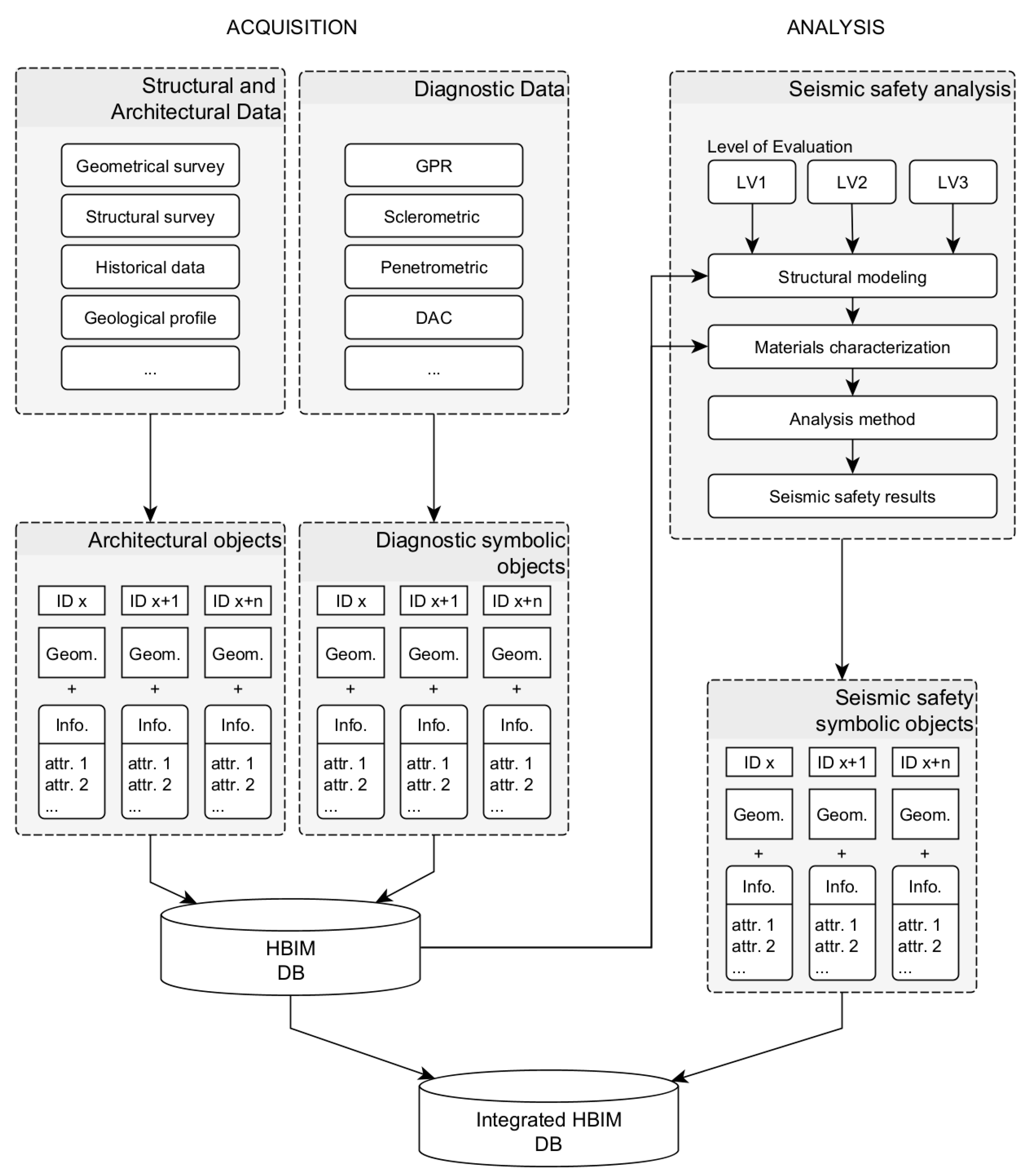
2.2. HBIM Database for Seismic Assessment

The results of modelling and data organization process is an integrated database (HBIM-DB) that collects all information and results acquired during the data acquisition process (Figure 2). The DB is structured to be easily accessible and adaptable to integrate information and data of various nature.
Thanks to the global three-dimensional view and various filtering visualization options, obtaining specific information is a quick and easy task. This avoids the data information loss and overlap typical of traditional archiving methods.
This model provides an excellent basis for various forms of data processing and analysis, such as the following: the development of materials and degradation of structural elements maps, historical mapping aimed to study the evolution of structural elements, and the ability to conduct restoration or maintenance projects or guidelines.
In this regard, application of the model to the seismic safety assessment has been investigated. The model potentially contains all the necessary information to characterize structural models aimed at such evaluation, following the Italian Guidelines [1]. Although now dated, this document still represents an excellent reference that emphasize of follow a path of knowledge of the structure from various multidisciplinary aspects, for example: structural historical evolution, material and construction survey, and mechanical characterization of materials and geotechnical aspects.
The combination of the knowledge acquired in the different areas allows the evaluation of a knowledge level and an associated confidence factor (CF). This is a coefficient between 1 and 1.35 that permits the reliability of the structural analysis model to be considered and taken into account in the seismic safety assessment, such as for an element of reduction in the material resistances, in models where these are considered, or a reduction in the capacity of the structure by reducing the acceleration corresponding to the various limit states, in the case of rigid body models.
The guidelines identify three levels of seismic vulnerability assessment, differentiated by the level of depth of the analysis (LV1, LV2, and LV3). LV1 analyses use simplified mechanical models derived from structural typology. LV2 and LV3, on the other hand, are designed to assess structural criticalities with respect to global or local behavior, providing significant information for decision making on strengthening or consolidation measures.
Independently of the level adopted, the objective remains the same: to assess the safety coefficient, known as the safety index (Is), which is derived using the ratio of the structure’s capacity and the expected seismic demand at the site.
LV1 and LV2 analyses are particularly valuable in case of CH architecture [23,24,25,26,27] due to the difficulty of comprehensively characterizing the mechanical behavior of masonry due to its heterogeneous nature. These analyses require less information than more sophisticated approaches—such as numerical methods, e.g., FEM—but provide an initial assessment of the structural safety of the building in terms of global and local response to expected seismic actions at the site.
To obtain sufficient knowledge and to reduce uncertainty in structural analysis models, it is appropriate to conduct a detailed diagnostic materials investigation campaign. This includes geometric and materials survey and evaluation of the condition and capacity of masonry and the dynamic behavior of the structure.
Regarding geometries, simplified analyses can be based on schematic geometric models rather than the details provided by laser scanner surveys. The use of simplified geometries does not have a significant impact on seismic safety assessment compared with the selection of mechanical parameters.
However, for more in-depth analyses using numerical modeling (LV3), different levels of geometric detail are required depending on the analyses’ procedures and modelling strategies [28].
The characteristics of masonry, such as its monolithicity, individual component characteristics (such as mortar and stone materials), type of masonry pattern, and internal distribution are sensitive aspects for simplified analyses.
These aspects can be evaluated using non-invasive testing methods such as sclerometric, penetrometric, GPR (ground penetrating radar), and other tests. Possible variations in materials’ behavior can be assessed by performing these on different parts of the building. The determination of seismic requirements depends on the dynamic behavior of the structure, which includes modal shapes and periods, and can be studied using dynamic identification methods.

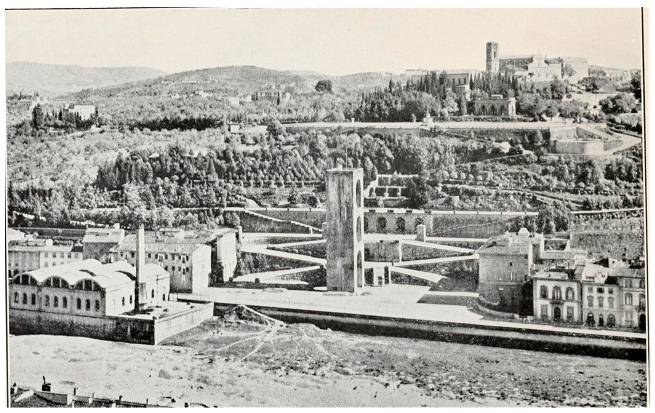
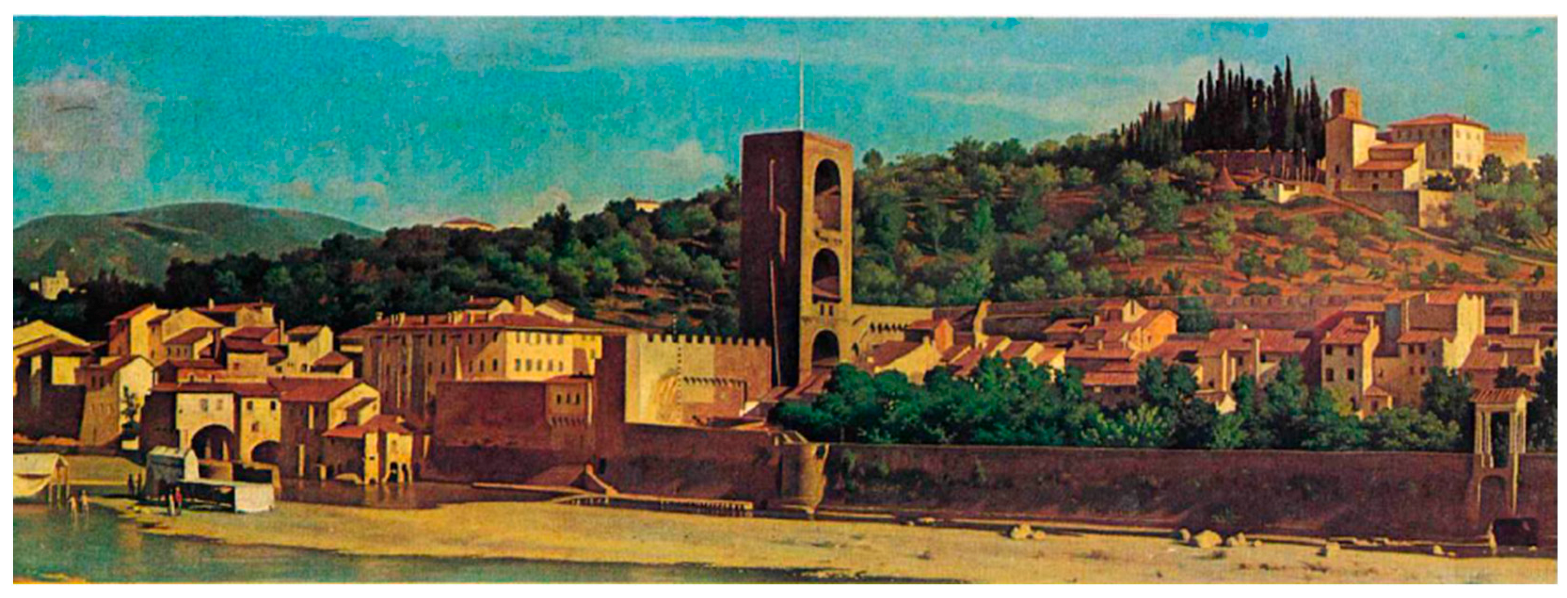
3. San Niccolò Tower: The Knowledge Path
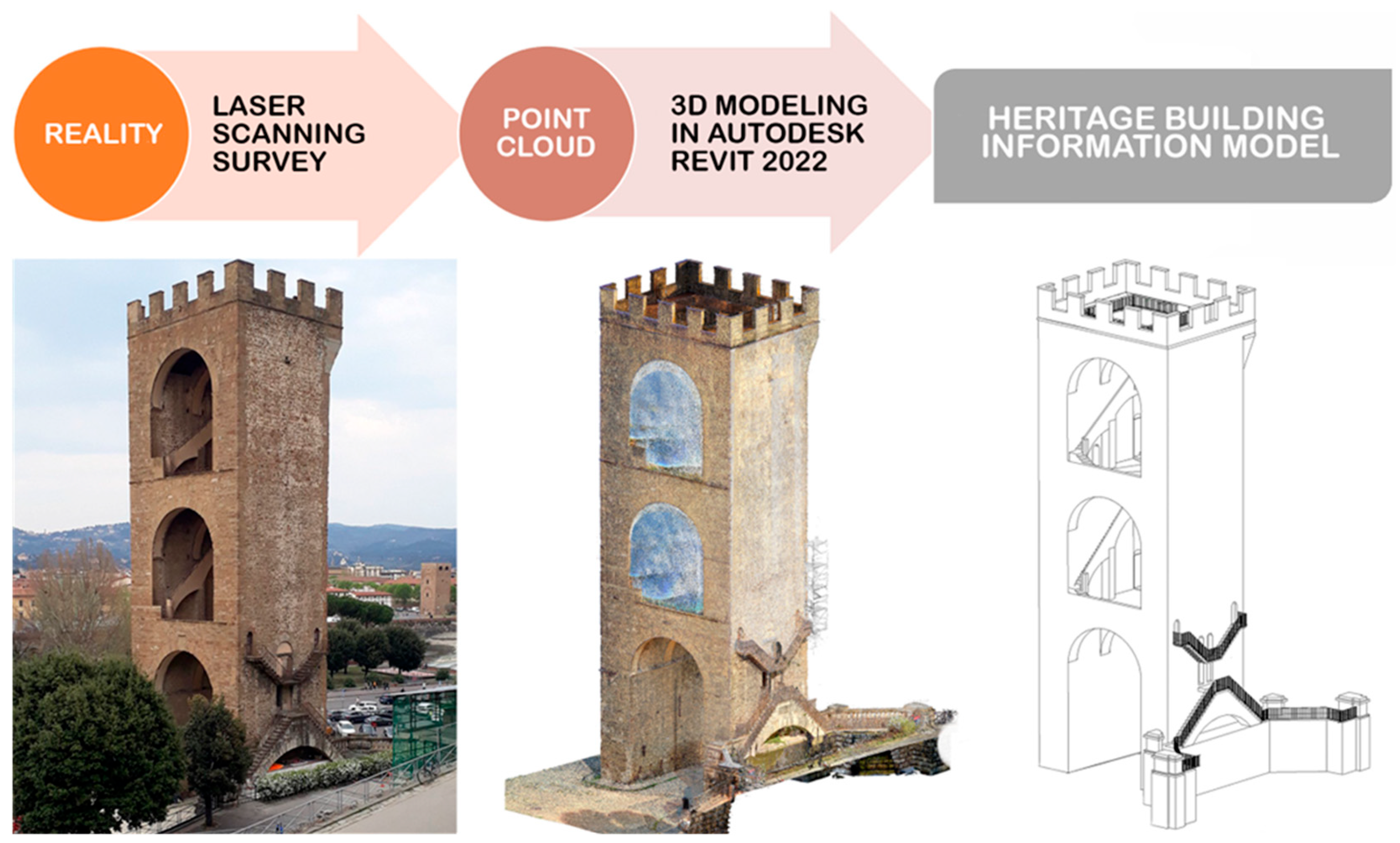
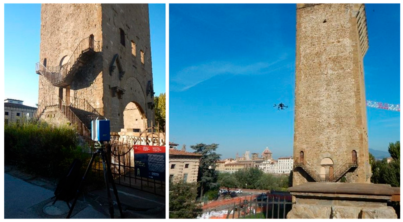
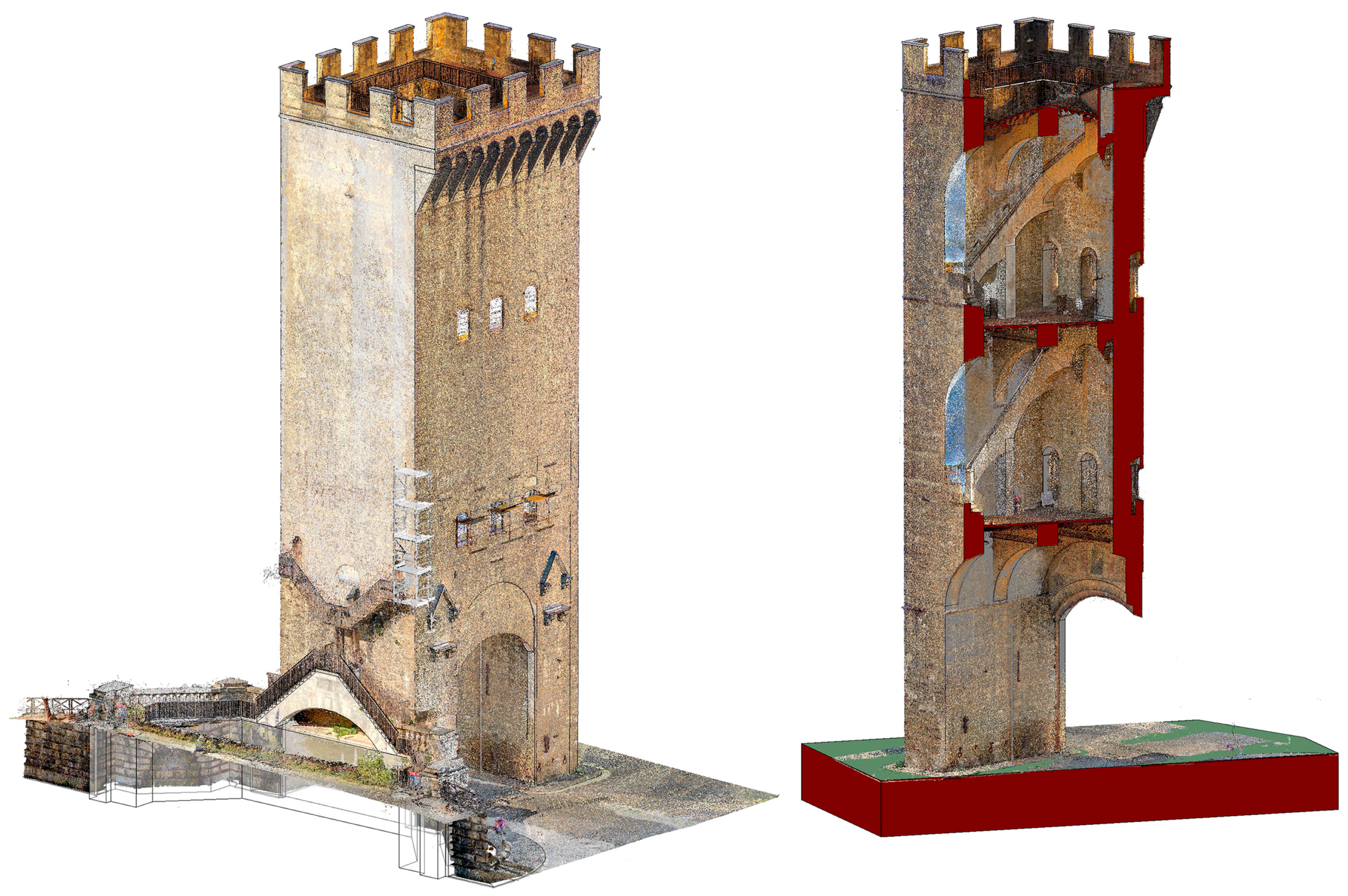
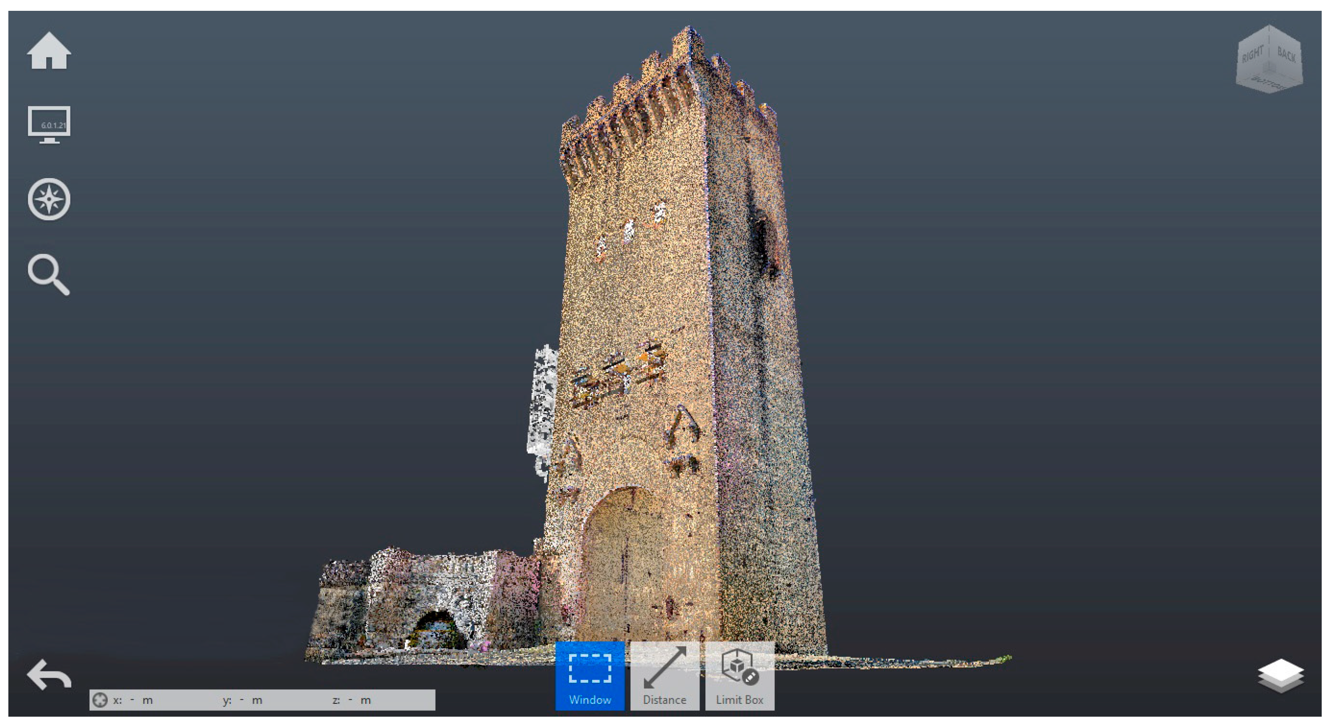
The information that can be incorporated into the previously described parametric system is diverse in nature, encompassing descriptive data, qualitative aspects, and interpretations arising from the analysis of acquired data by various operators involved in the study process. In the following chapter, we present the key information collected during the knowledge path on the case study of the San Niccolò Tower.
The Tower, part of the third ring of city walls erected in the 14th century, was designed in 1328 by Andrea dell’Orcagna and executed by the craftsmen of the Opera del Duomo. During the siege of Florence in 1530, it remained the only structure to retain its original height (approximately 40 m), thanks to the protection provided by the hill and the Forte di San Miniato against artillery strikes (Figure 3). In the renovations for Florence’s capitalization in 1870, the tower was isolated and equipped with the current external stairs, allowing access from the side facing the ramps leading to Piazzale Michelangelo. During the 1930s, restoration, battlements, and corbels, previously demolished due to deterioration, were reinstated (Figure 4).
Nowadays the San Niccolò Tower is configured as a gate/tower structure consisting of two pillars approximately measuring 10 m × 3.3 m, connected by a curtain with a thickness of 2 m. Six transversal arches connect the two pillars, supporting the wooden floors of the two intermediate levels and a pitched roof. During the restoration in the 1930s, the facade reintroduced corbels to support a projecting walkway with machicolations (overhanging a total of 1.5 m), and merlons were reconstructed with a thickness of 45 cm along the entire perimeter of the top of tower.
To understand its genesis, composition, and functioning, an intensive knowledge path was undertaken, as stipulated by the relevant Italian regulations [1], calibrated for assessing the structural performance of the construction. Given its historical nature, the use of new technologies and indirect investigative tools proved essential to preserve the structure from further detrimental interventions on materials.
Another non-invasive investigation tool employed was dynamic identification testing [29]. This is a highly significant activity that provides crucial information about the dynamic behavior of the structure in the presence of ambient vibrations, including frequencies and modal shapes. Furthermore, the results of dynamic identification can be used to validate numerical models, enhancing the accuracy of structural behavior predictions, and leading to a better understanding of the expected seismic response. For further insights regarding the dynamic identification campaign, please refer to [30].
Further information about the structure and its dynamic characteristics can be found in [31].
The following sections detail the diagnostic investigations conducted to understand the structural organism and assess its condition, with the aim of obtaining information useful for structural evaluations. All information has been collected and integrated into the tower’s cognitive BIM model.

3.1. Digital Survey

A foundational step for the accurate implementation of building diagnostic investigations is the geometric survey of the structure. Geometric surveying plays a crucial role in understanding a construction project, as it enables the collection of necessary information to comprehend its metric and morphological aspects. This, in turn, delineates the current state of the construction, serving as the basis for assessing findings from historical research considering the actual conditions.
For this research project, the chosen approach involves the utilization of laser scanning technology to achieve a highly dense and accurate result within shortened timeframes. The employed instrumentation includes the Cam2 Faro Focus S70 scanner and the Zoller + Fröhlich IMAGER 5016 (Figure 5).
Individual range scans collected during the campaign were then consolidated via processing in Recap Pro (©Autodesk) [32], a software utilizing cloud-to-cloud alignment (Figure 6). Additionally, the survey was complemented by a series of aerial photographs captured using a drone and ground-level photographic documentation.
The geometric survey allowed the detection of deviations from vertical alignment in two primary walls, with the largest displacement observed at the top of the tower, reaching approximately 10 cm. These deviations may have been caused by the various structural modifications the building has undergone over time.
Regarding the crack patterns, serving as an indicator of the state and behavior of the structural organism, they have been present since the mid-nineteenth century, likely resulting from the thrust exerted by the arches supporting the roof embrasure. These arches were later replaced by the current wooden covering. Currently, the visible damage on the east and west sides has been repaired, and no new cracks are observed on the external facades. However, internally, partially reactivated damages are noted in correspondence to the window openings.

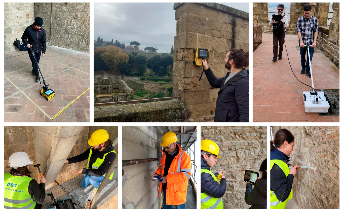
3.2. The Diagnostic Campaign

The diagnostic testing campaign conducted on the construction (Figure 7) allowed the mechanical characterization of the constituent materials and structures, thereby establishing a model on which to base the analysis of the resistance system. As previously mentioned, the diagnostic campaign was conducted, prioritizing the use of non-destructive technologies and touchless instrumentation to ensure the preservation of existing materials. Various methodologies and tools were employed, including ground-penetrating radar (GPR) investigations aimed at assessing potential voids within the masonry and the distribution of stone material in the substantial thickness of the walls. In particularly significant areas, endoscopic investigations and DAC tests were utilized to evaluate the percentage distribution of stone material in the masonry. Sonic investigations were employed to estimate the velocity of sonic transmission in the in situ stone materials and the overall masonry structure. Specific analyses on construction materials involved stone material (sclerometric tests) and mortar (penetrometric tests).

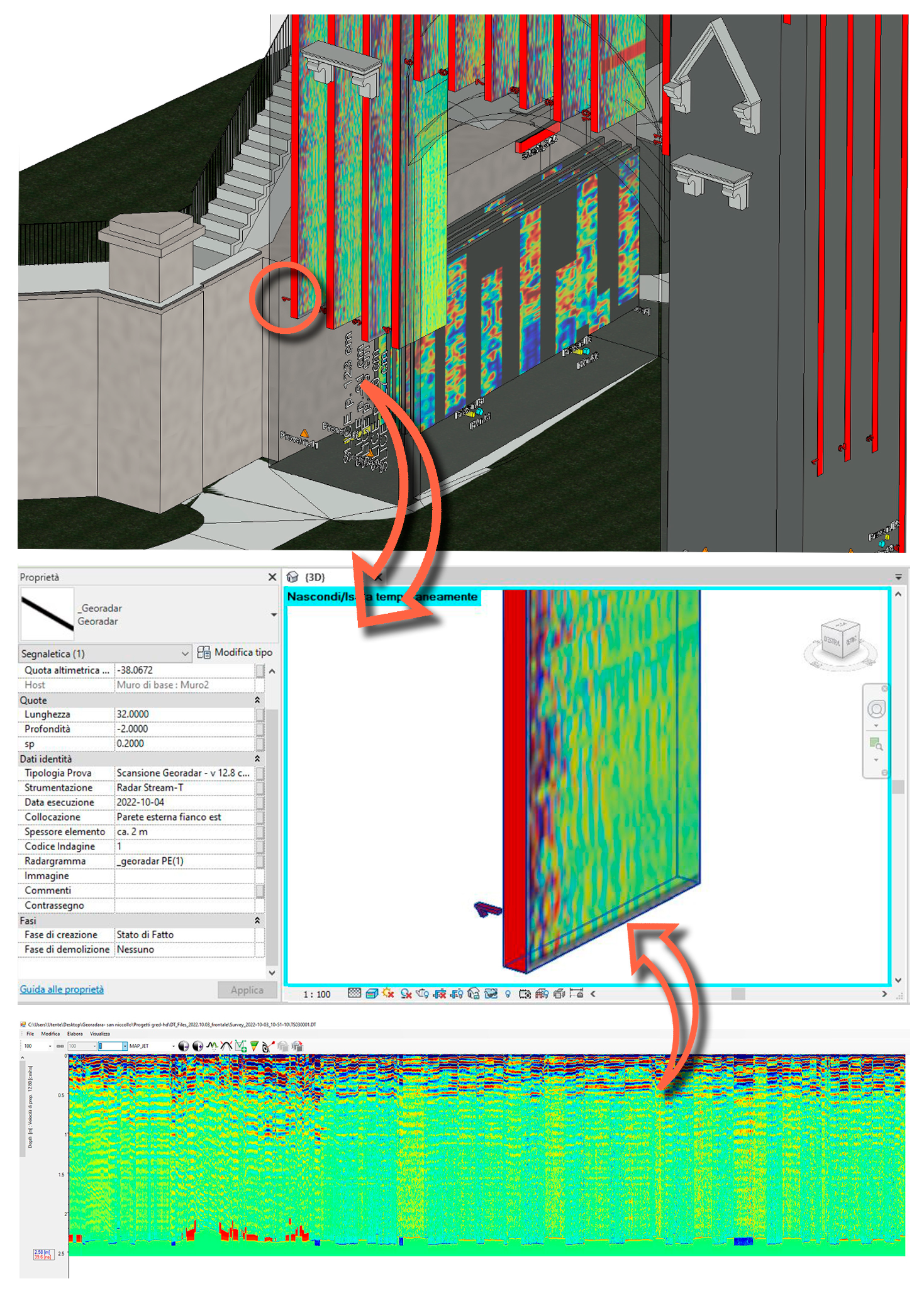
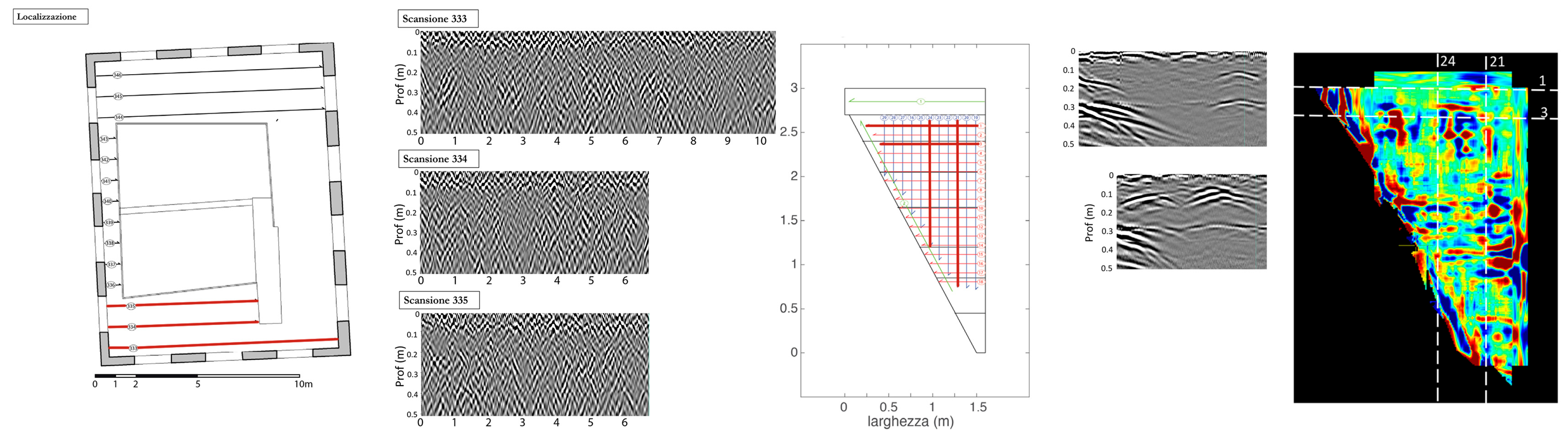
3.2.1. Ground-Penetrating Radar (GPR) Investigations

Ground-penetrating radar (GPR) surveys were conducted using different radar systems. The Stream T, employed for external masonry investigations, represents a new generation of GPR antennas, operating in a contactless mode and maintaining approximately 15 cm from the surveyed surface. The C-thrue, used to examine floors, battlements, and corbels, provides a high level of detail but within a limited investigable thickness (<70 cm). Finally, the RIS-ONE, employed for terrace assessments, allows for investigations of elements with substantial thickness (>200 cm). From the results of investigations carried out on the masonry, for the east and west sides and the internal ground level, the external masonry facade consists of rows of stone blocks and mortar with a thickness of approximately 30–50 cm, followed by a compact masonry without significant issues or voids.
Concerning the floors, first and second floors, the presence of floor tiles and a “caldana” above small tiles supported on beams with a 50 cm span, visible from below, resting on intermediate arches. On the rooftop terrace, a consistent presence of a series of reflectors in the first 15–20 cm, followed by another layer of about 20 cm before the structural mass (Figure 8). An exploratory survey identified tiles, their bedding, membranes, the slab, and then masonry. GPR investigations on floors were limited to the top 50 cm. Merlons consist of squared Pietraforte blocks set in thin layers of mortar, lacking internal flaring to accommodate additional mortar bedding. A solitary element disclosed the presence of a metallic component. Corbels display a prevalent condition of deterioration, with both existing and potential exfoliation, featuring thickness ranging from 2 to 10 cm (Figure 8).

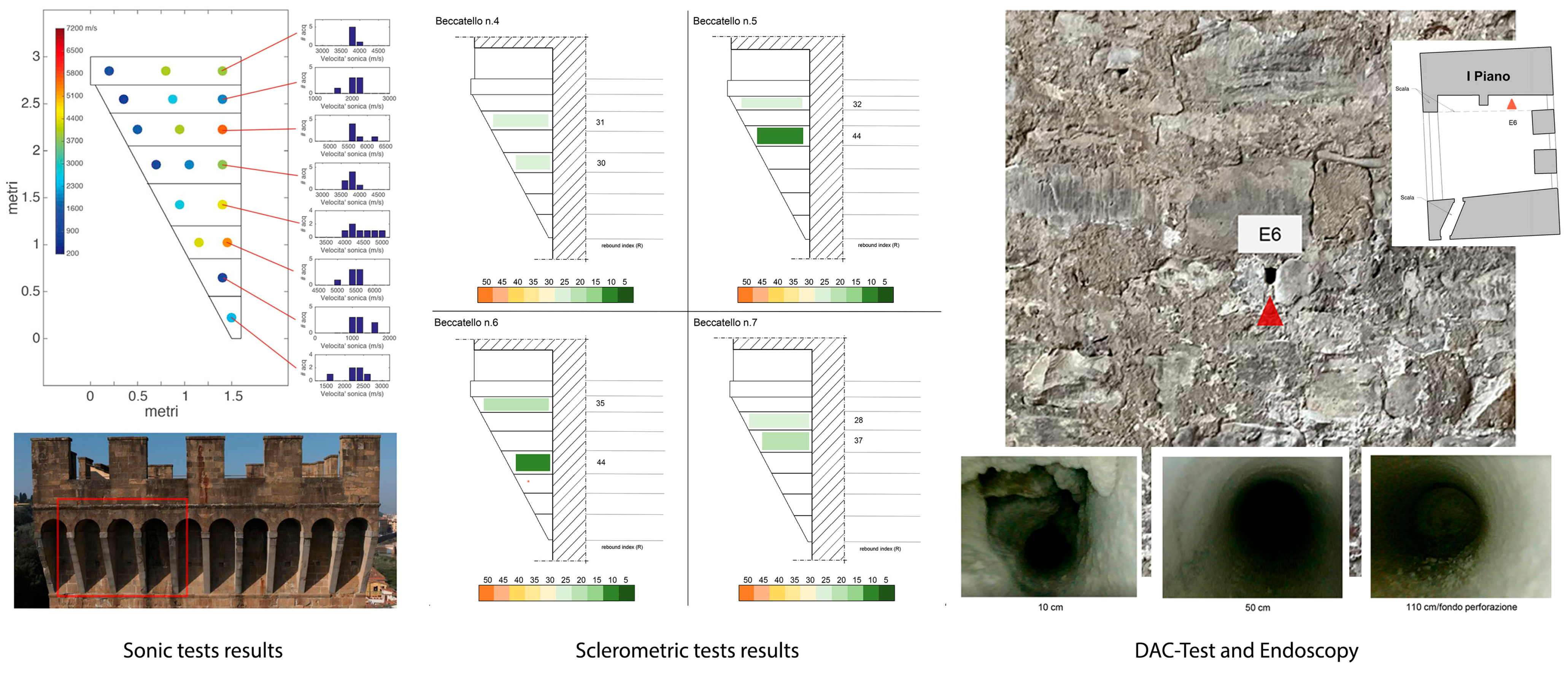
3.2.2. Sclerometric and Penetrometric Tests

Sclerometric tests were conducted using the Schmidt Hammer N-type 58-C0181/N. Results from the tests on Pietraforte yielded JCS values between 67 and 170 MPa, indicating a good to excellent state of preservation relative to an inherent compressive strength (σc) of this material around 130 MPa. However, intentionally conducted tests on visibly degraded elements yielded values up to a maximum of 70 MPa. Regarding the corbels, rebound values (R) were obtained, indicative of a degraded surface, with degradation progressing for individual Pietra Serena rods from the front to the masonry and from top to bottom (Figure 9). Penetrometric tests on mortar were conducted using DRC instrumentation with the insertion of a metal-tipped probe, measuring the penetration in millimeters after 10 strikes. The investigation focused on the original bedding mortars, following the removal of the surface layer applied during restoration in the last century. Via curve analysis and correlation formulas, resistance values were derived, proving to be more than satisfactory, with an average around 20 MPa, consistent with findings in the literature on Florentine mortars executed by the craftsmen of the Opera del Duomo [33].

3.2.3. Sonic Tests

Using the Novasonic U5200 CSD instrumentation, a campaign of direct transmission sonic tests was conducted, enabling the detection of the sonic transmission velocity of in situ stone materials and the overall masonry structure. Velocity values reached Vp = 2900 m/s in the pylon masonry and Vp = 1900 m/s in the frontal curtain masonry, suggesting a high degree of compactness in the masonry as a whole, even in substantial thicknesses. In contrast, the tests on the corbels revealed a general state of degradation (Vp < 1000 m/s) (Figure 9). Regarding the merlons, minimal velocity values (<1500 m/s) are associated with the more exfoliated blocks, indicating widespread deterioration, while those in good conservation condition are linked to Vp values exceeding 4600 m/s.

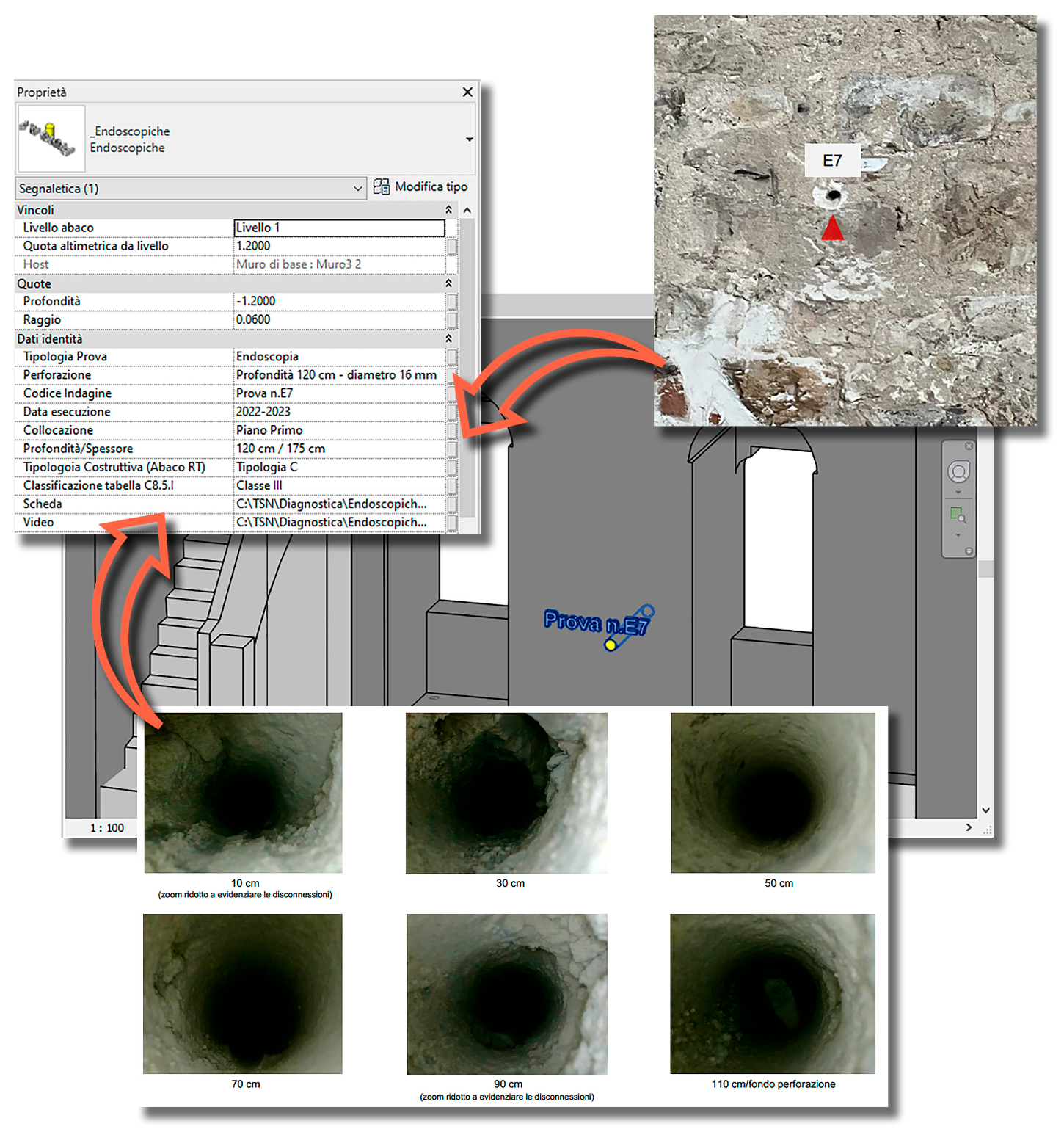
3.2.4. DAC-Test and Endoscopic Analysis

The Ø16 mm drillings, conducted along mortar joints, penetrated into the masonry for 120 cm at a height of approximately 120–150 cm from the floor. For the two pillars, the examination of masonry compactness during drilling and observation of the cuttings led to the conclusion that the walls are well constructed and compact, with no internal voids. The estimated stone/mortar ratio is approximately 70% stone and 30% mortar for the walls from ground to the second floor, and about 55% stone and 45% mortar for the walls from the second floor to the ridge. On the first and second floors, perforations made on the internal surfaces of the Tower’s walls frequently revealed small voids after the first stone course (within the first 50 cm). Beyond this depth, up to 120 cm, the core appeared compact and well knit. From endoscopic analysis, the curtain wall appears slightly less compact, with more widespread but still very modest-sized voids, resulting in a stone/mortar ratio of around 50% (Figure 9).

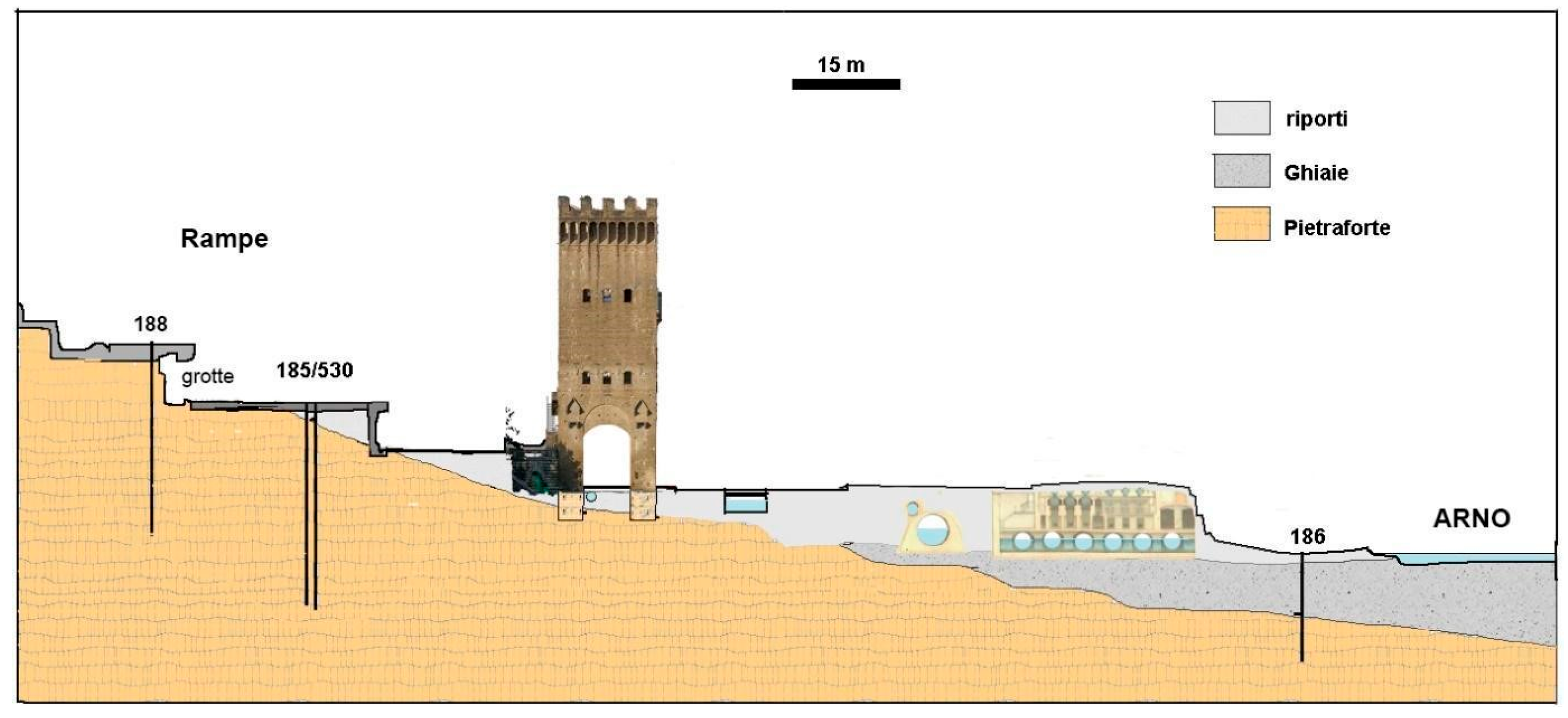
3.3. Geological and Seismic Characterization of the Area

The geological framework of Florence has been characterized in its three-dimensional configuration in various studies [34,35,36], culminating in a Geodatabase (GDB) containing over 2200 boreholes, representing a critically important knowledge document. Groundwater measurement data, collected by the Municipality a few years ago from a well near the Tower, indicate a level approximately −3 m from the ground surface, with a seasonal annual variation of about 1.5 m, and overall equilibrium with the Arno River.
The detailed geological situation, inferred from the boreholes in the area, reveals a lithoid substrate composed of Pietraforte, forming the hill and bedrock of the area of interest (Figure 10). This is overlain by historical anthropogenic deposits and backfills, reaching a thickness of up to seven meters in the marginal area between the Arno River and the hill, followed by clean gravel from the Arno riverbed. The following reference parameters are attributed to Pietraforte: seismic velocities Vp ≥ 2100 m/s and Vs = 900 m/s; UCS = 130 MPa [37]. In the geological–technical mapping accompanying the seismic microzoning studies, the area does not appear to be affected by the known historical instability present on the northern slope of the San Salvatore al Monte hill.
Data acquired from the station installed at the base of the Tower were used to calculate the horizontal-to-vertical spectral ratio (HVSR), providing both the peak frequency where seismic shaking amplification from the overlying soils is expected and an estimate of the thickness of the covering layer overlying a rigid substrate. In the specific measurement at the base of the structure, the analysis reveals a high-frequency amplification peak around 17 Hz, consistent with the shallow depth (a few meters) of the rigid substrate, in agreement with the geological section. The uniformly distributed azimuthal pattern of the spectral amplification peak confirms the reliability of the result. Therefore, according to NTC2018 [38], the area in question is classified as a category A soil, and seismic checks at the foundation should be based on rigid soil conditions. The city of Florence has historically been the epicentre of significant earthquakes, with estimated magnitudes consistently below 5 ML [39]. Seismogenetically, the Florentine area exhibits moderate seismic activity, resulting in local earthquakes with an Imax of VIII on the MCS scale.
In relation to the recent development of seismic microzoning for the Florentine area adopted by the Municipality, the area around the San Niccolò Tower, considering the presence of anthropic backfills, is assigned a surface amplification factor of 1.75 and falls within seismic microzoning Level III, No. 4.

4. San Niccolò Tower: The Parametric Informative Model

The geometric and material knowledge acquired during the analyses and checks carried out on the building constitute a database of information which, linked to a geometric model, defines the concept of BIM.
In this section we will describe the process of creating and organizing the information model of the tower of San Niccolò aimed at managing the data from research, surveys, and interventions. All operations were conducted using the commercial BIM modeling software Autodesk Revit [40]. The result is a database that, linked to the virtual representation of the architecture, constitutes a valid tool for the protection of the asset and the sharing of information with the various figures involved in the management of the building.
The case study examined is part of the research line that studies the possible applications of this methodology to the knowledge of historic buildings. In particular, the aim of these studies is to validate the applied workflows and discuss the problems encountered during the application. Via the application of a methodology to multiple case studies with different complexities it is possible to experiment with different paths and solutions.

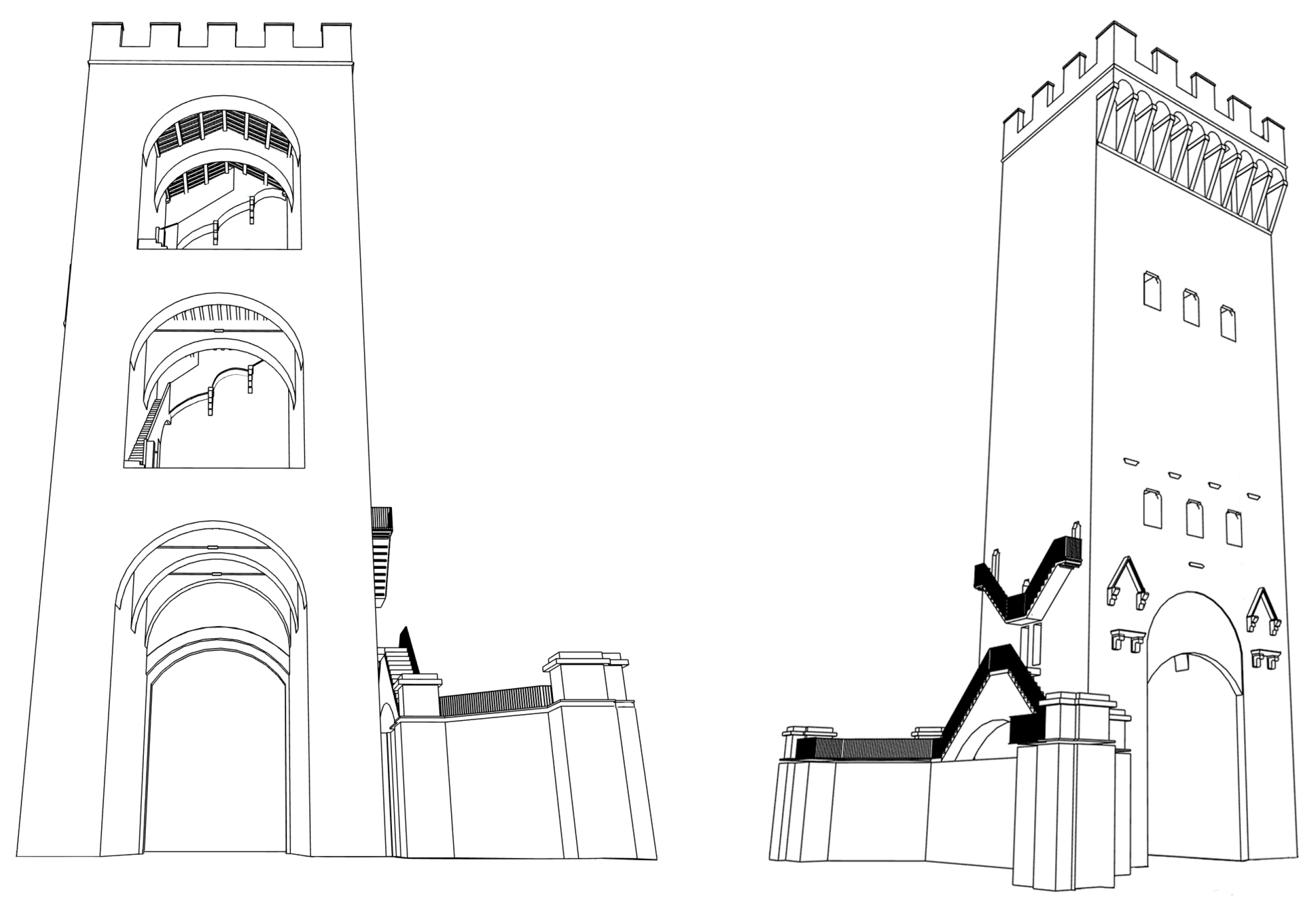
4.1. The Creation of the Geometric Model

The point cloud from the TLS and aerial survey was the morphological–dimensional guide for the modelling of the Tower of San Niccolò (Figure 11). The information coming from the historical analysis from the diagnostic investigations has also contributed to increase the material and evolutive knowledge of the structure. In the Autodesk Revit modelling environment, modelling was made possible by two types of tools:
-
the use or creation of system families, loadable and adaptive;
-
the use of several types of views (plans, sections, and elevations).
To create the walls, floors, and roof, the system families were used. The walls, specifically, were inserted after modifying the types available in the program, varying their stratigraphy and thickness. These families do not always adapt to the unevenness that characterizes the existing heritage. The out-of-square and out-of-plumb conditions were managed using specifically created families, based on generic metric models that were sometimes adaptive, solid, or subtractive depending on the specific case.
Uploadable families were created for doors, windows, and decorative elements. The specific family was not used for the stairs since these elements, of a peculiar shape, are characterized by strong irregularity; they were then managed using combinations of uploadable families and local models. For the wooden parts of the floors, families of beams and joists present in the Revit libraries or specifically created due to the particular geometry of the sections were used.
Furthermore, the use of adaptive families allowed the overcoming of geometric difficulties linked to the presence of unique and irregular shapes. The arches were modelled using generic adaptive metric models of solid subtraction type. For the creation of these parametric objects, the control points through which the object is inserted into the model are chosen and some reference elements are drawn, which will constitute the profiles used by the software to generate the solid or void.
These families are therefore particularly interesting when interfacing with the existing heritage, due to their ability to conform to local peculiarities directly, without resorting to angular parameters. Customized families have been created, including those relating to the categories of diagnostic objects and seismic vulnerability. Finally, the use of multiple views used simultaneously allows the user to model from the point cloud using parametric objects.
The result (Figure 12) can be framed, according to the definitions of the BIM Forum, in an LOD 300: “the quantity, size, shape, location, and orientation of the element as designed can be measured directly from the model without referring to non-modelled information such as notes or dimension call-outs” [41].
In the context of Italian legislation [42] and LODs for restoration, the work can be squared in a LOD F. This level expresses the “as built” of the structure by introducing information on the current state, degradation, and temporal programming as non-geometric content of the planned maintenance interventions. From the point of view of documenting the current state, the digitalization of the knowledge acquired on the structural and conservative structure of the tower is therefore included.

4.2. The Organization and Insertion of Information Content

The information collected during the cognitive process was unified and rationally organized, enriching the three-dimensional representation with extensive and varied information content to be digitally managed in a logical and orderly way.
The information content included in the template can be classified as follows:
-
historical data;
-
data from the structural survey: construction characteristics of structures, material characteristics, cracks, etc.;
-
data from diagnostic campaigns: non-destructive or mild partial destructive investigations, data from dynamic monitoring;
-
results of seismic vulnerability analyses.
Some of the information content has already been used and inserted during the modelling phase: historical information, geometric information from the point cloud or from the structural survey for example. The data of the structural survey were entered mainly via the stratigraphy of the objects, the geometric shape, and the materials. For all other categories of information, however, an intelligent object parameterized with dimensional rules and equipped with other parameters for non-geometric information was created. Among the types of parameters used are textual parameters that make the contained data directly readable (embedded data) or URL parameters corresponding to external files stored in specific folders (linked data). For each type of diagnostic investigation, a personalized parametric family with a defined geometry was prepared and placed in the exact place where the investigation was performed. This also provides the opportunity to quickly compare the results of different tests performed on the same part of the structure. The parameters entered include the type of test, the investigation code, the date of execution, the equipment used, and the link to the data sheet. (Figure 13 and Figure 14).
The data processed during the seismic safety analysis were linked to the model by means of a parametric object, which provided access to the information collected on the seismic action assessment via URL.
The use of Revit’s schedules provides a unified framework of investigations closely linked to the model via a one-to-one relationship that allows the database to be easily interrogated. Information content can always be updated using schedules and filtered or displayed in model views.

4.3. Seismic Vulnerability Assessment via a BIM-Based Approach

Thanks to the database developed as previously mentioned, the unified framework of investigations involving the Tower can be consulted directly on the model. The results of the diagnostic campaign, combined with the walls and floors characterization, are integrated into the model using specific parameters. The incorporation of geological data into a three-dimensional environment has facilitated the instantaneous visualization of relationships between the subsurface structure of the area and the building. Geological stratigraphy has been modelled by assigning relative characteristics. In the pre-analysis phase, the model transforms into an interactive database, a valuable tool for extracting and processing data to conduct seismic safety analyses of the tower. Below are described the simplified seismic vulnerability analyses performed using the BIM approach to modelling and sharing results.

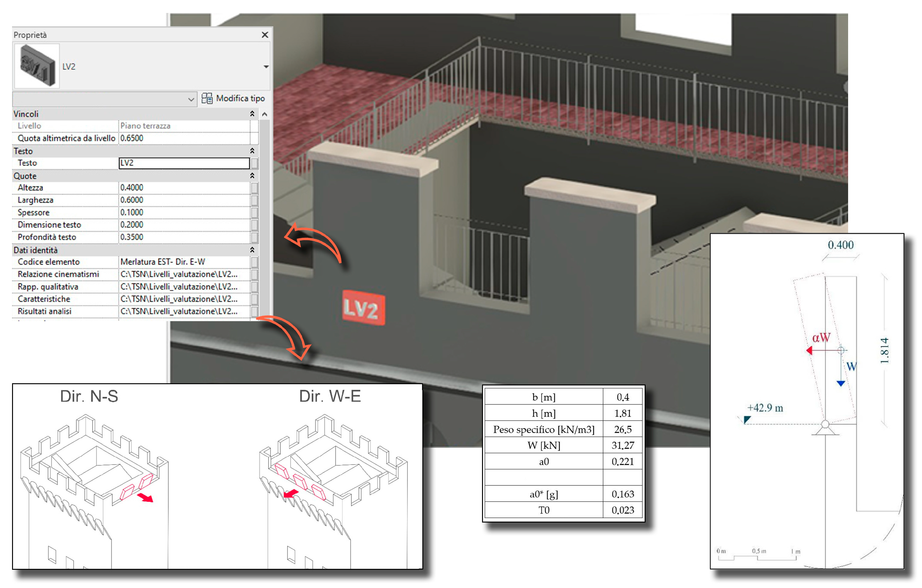
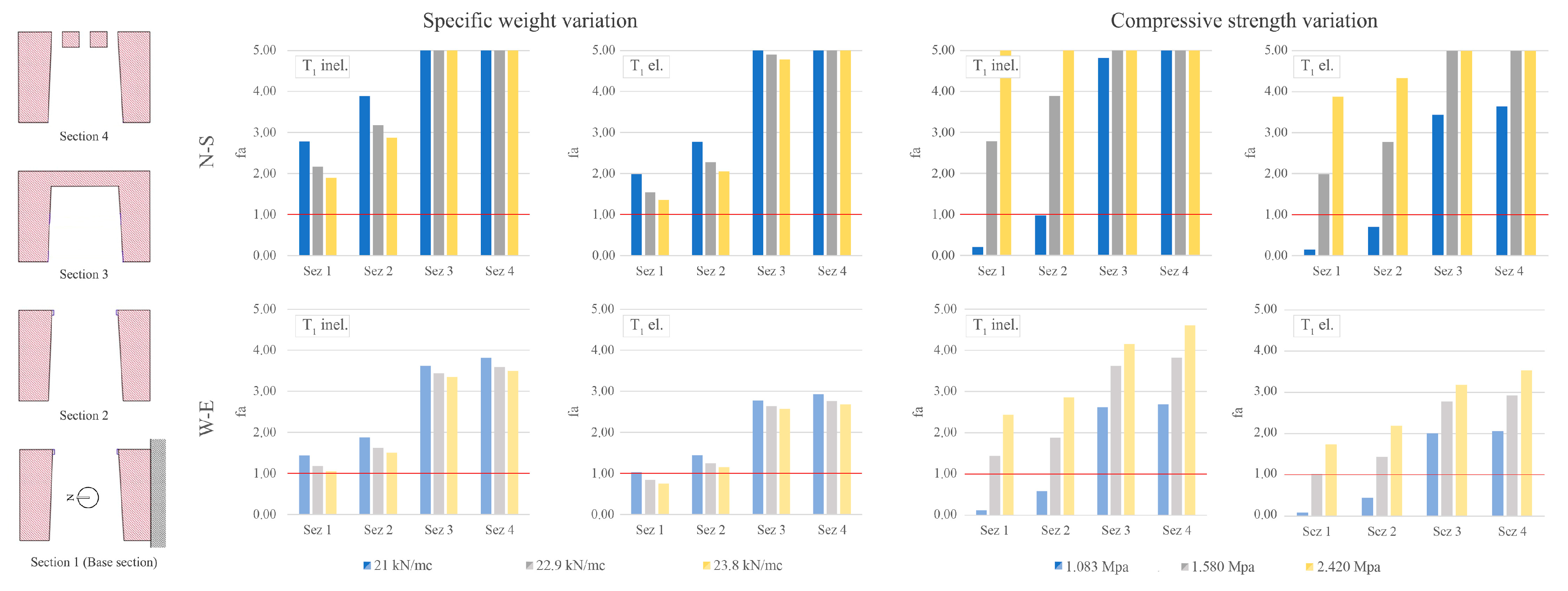
4.3.1. Simplified Seismic Assessment—LV1 and LV2

As indicated in Section 2.2, the seismic safety assessment of the tower has been developed following the first two levels of assessments (LV1 and LV2) proposed by the Italian guidelines [1].
The seismic demand has been characterized following the Italian standard [38]. A nominal reference period of 50 years has been assumed, with a use coefficient of 1.5 (use class III), obtaining a return period (TR) of 75 years. Seismic safety was computed with respect to the life safety limit state (SLV) of 712 years of return period, considering a subsoil category A (according with geological profiles) and considering a topographical category T1, resulting in a maximum ground acceleration of 0.149 g.
The first level of assessment (LV1) involves the application of a simplified modelling procedure that evaluates the structure’s global behavior. The safety index can be calculated in terms of the return period of the seismic action leading to the considered LS and the corresponding reference return period, or similarly in terms of the acceleration factor (fa), defined as the ratio between the ground acceleration leading to the LS and that corresponding to the reference return period (both related to soil category A).
In the case of towers, bell towers, and other structures with predominant vertical development, for the LV1, guidelines provide a simplified calculation scheme based on collapse due to pressure bending. This method considers the structure as a cantilever beam subjected to horizontal forces and to its own weight, and checks for crushing failure in the compressed zone in different sections. The structure has been divided into uniform sections, considering openings, detachment points, section reduction, and changes in material or construction phase.
This procedure is based on imposing the equivalence between the ultimate resisting moment (Mui) and the acting moment in each individual i-section. This allows the ordinate value of the elastic response spectrum corresponding to the attainment of the SLV in the i-section (considering the confidence factor FC) to be derived, as follows:
S e , S L V , i T 1 = q g M u i k = 1 n z k w k 0.85 W k = i n z k 2 w k z i   * k = i n z k w k F c
where zk is the heights of the center of gravity of sectors i and k with respect to the foundations; wi and wk are the weights of sectors i and k, respectively; Se(T1) is the ordinate of the elastic response spectrum as a function of the first period T1 of the structure according to the direction considered; z i   * is the height of verification i-section in relation to the base; and q is the behavior factor representing the dissipative capacity of the structure.
A more detailed explanation of the theoretical assumptions can be found in [26].
In this case, due to the significant asymmetry of the tower’s plan, both main directions of the section were considered in the check. The resisting moment of each section has been evaluated analytically using the eccentricity method, similar to that reported by [43].
Considering the investigation conducted and the simplified nature of the mechanical model adopted, the use of parameter sensitivity analysis is valuable. It allowed the effective understanding of the influence of the most uncertain single parameters on the structure.
Different specific weight and compressive strength values were considered. The adopted compression strength values were as follows: (i) 1.083 MPa, considering the minimum value of the “stone masonry with good texture” masonry class [44]; (ii) 1.58 MPa, considering the maximum value of the “stone masonry with good texture” masonry class; and (iii) 2.42 MPa, considering the minimum value of the “squared stone block masonry” masonry class.
Considering specific weights of stone and mortar equal to 26.5 kN/m3 and 17.5 kN/m3, respectively, different specific weights were assumed for the masonry: (i) 21 kN/m3, according with “stone masonry with good texture” masonry class; (ii) 22.9 kN/m3 considering a stone/mortar ratio of 60/40; and (iii) 23.8 kN/m3, considering a ratio of 70/30.
For the two main verification directions (NS and WE), the periods related to the predominant modal form in the verification direction were considered in the calculation. The first mode for the NS direction and the second mode for the WE direction have been considered. In addition, the periods were considered with the structure in a cracked configuration (increasing the period by 40%), as well as in the elastic phase.
The obtained results of sensitivity analysis for the first four sections considered are reported in Figure 15. The results clearly show the sensitivity of this mechanical model to the assumed compressive strength parameter of the masonry. In this case, a greater criticality was observed in the basal section, especially along the west-east direction (parallel to the shorter side). Nevertheless, the average of values considered for masonry compressive strength returned safety indices above one, providing a satisfactory overall evaluation.
These results, although obtained via a simplified modelling procedure, provide essential information highlighting the level of seismic vulnerability of the tower in relation to the site risk, considering various aspects related to the materials constituting the structure.
The second evaluation level (LV2) consists of the assessing of local vulnerabilities of the structure by means of the kinematics method. The reference model is the limit analysis of the equilibrium of masonry structures, considered as rigid blocks not resistant to tension. The kinematic approach is based on the evaluation of the horizontal action sufficient to activate the collapse mechanism.
In accordance with Italian standards [38], the safety index has been calculated using linear kinematic analysis via the relationship between capacity and floor level demand in terms of spectral accelerations using the following relation:
I s , S L V = a 0 , S L V * q S e Z , k ( T , ξ , z )
where SeZ,k(T, ξ, z) is the contribution to the floor response spectrum provided by the k-th mode of the structure of period proper Tk, equivalent viscous damping ξ, and at z height of the kinematism; q is the behavior factor usually chosen equal to two; and a 0 * is the spectral trigger acceleration of the kinematism of the equivalent system.
Considering the generally positive results of the structure in the LV1 analyses, the local vulnerabilities were focused on the non-structural elements, such as the merlons. Numerous case studies in the literature highlight the susceptibility of merlons to oscillations induced by seismic activity [45]. Overturning is possible if the merlons are not reinforced with vertical bars within the masonry. Structurally, a merlon can be considered as a cantilevered beam, subject to flexure. After a crack forms, it behaves as a rigid block capable of sliding or rotating. Since these elements are typically located on top of structures, it is essential to consider the contribution of the underlying structure in the evaluation of seismic demand [46]. As in LV1, it is important to take into account the different dynamic behavior of the structure in relation to the direction of the assumed seismic action for the verification. For this reason, in this case, given similar geometric characteristics and the same height of the merlons, four configurations were analyzed by considering the first two periods of the structure in both elastic and inelastic phases.
Table 1 shows the safety index calculated for different directions of seismic action. Safety index values for the analyzed assumptions consistently exceed one, meeting the performance criteria for life safety limit state (SLV).

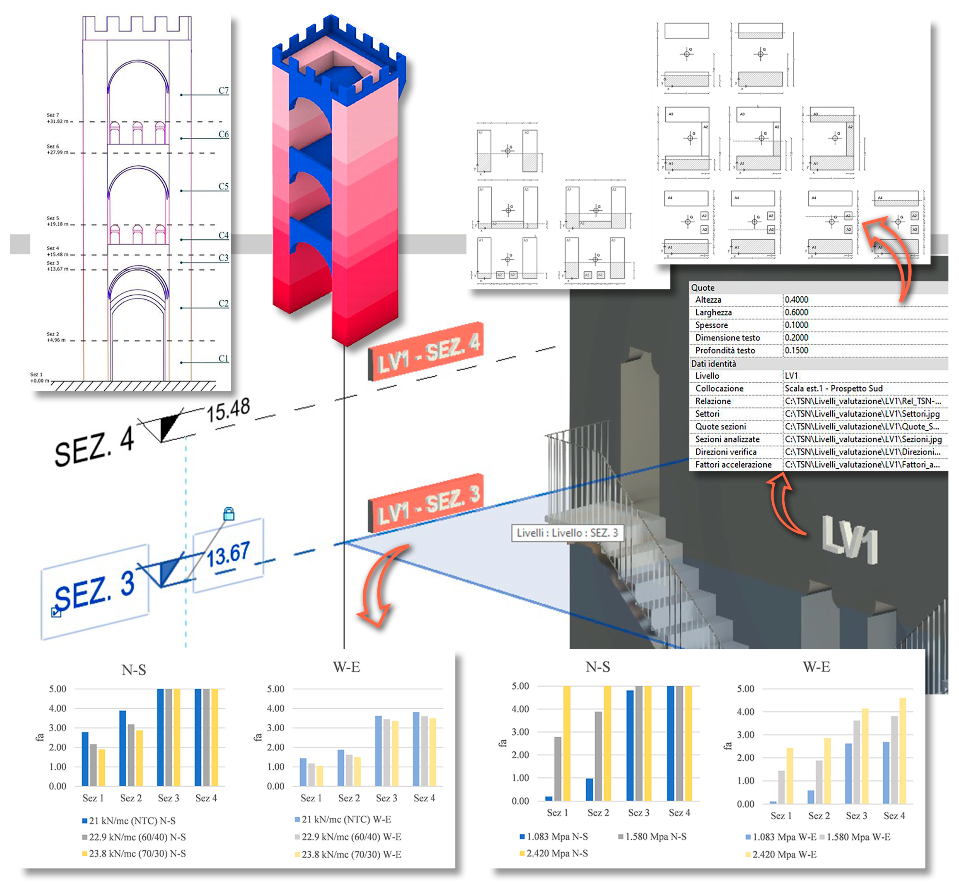
4.3.2. Seismic Vulnerability Data Insertion and Organization

The integration and organization of data in the model is crucial to the clear communication of seismic vulnerability assessment information.
Similarly to data obtained from the diagnostic campaign, this was performed using a customized parametric family containing insights related to the seismic analyses.
The integrated information not only includes the analysis results, but also explains all the methods and settings adopted. For example, information about the mechanical model used and its theoretical assumptions, as well as the parameters used in the calculations, such as the mechanical properties of materials and the geometric properties of various elements.
Regarding LV1, Figure 16 shows the different sectors and sections considered for each verification direction. Via the three-dimensional visualization, it is easy to identify the position of the most critical sections based on the direction of seismic action to which the structure is most sensitive.
Similarly in the case of LV2, Figure 17 highlights the information contained in the model, such as the hypnotized kinematic mechanism scheme, its geometric characteristics, and material specific weight, as well as the variation in the seismic demand.
A key benefit of this organization scheme is its accessibility and clarity. Stakeholders involved in the recovery process can easily access and interpret results, facilitating decision-making processes such as the planning of intervention aimed at improving seismic performance. In addition, the systematic organization of data makes it possible to identify the most critical areas and the most vulnerable local elements, facilitating the prioritization of interventions.

5. Conclusions

This paper presents the application of the HBIM methodology to manage experimental information obtained from diagnostics up to the structural evaluation phases of San Niccolò Tower/Gate, one of the access gates to the fourteenth-century city of Florence. In this case study, the main objective is to create a historic building model based on interdisciplinary research.
The authors collaborated to collect information to define an HBIM model. The model collects and archives the information derived from the knowledge and structural evaluation process. Thanks to a detailed three-dimensional survey, it is possible to rebuild the geometry that adheres to the state of the building. The historical information allowed us to reconstruct the evolutionary phases of the building and contextualize them in the model. The diagnostic campaign provided the main mechanical properties of the materials that constitute the structural components. All this information contained within a single platform allows for integrated reading.
The first results of the structural assessments, carried out according to the Guidelines, allow a positive judgement using the LV1 assessment; in fact, the structure presents a safety index greater than one considering the average values of the mechanical properties of the materials. Similarly, LV2 assessment of merlons returns favorable values.
Preliminary information and structural assessments can support decision-making processes that often involve multiple institutions and actors. The BIM approach therefore allows for effective collaboration between parties, improving the process of management, valorization, and protection of architectural works.
Thanks to the accurate and constantly updated archiving of information, it is possible to define the state of preservation of the building at any given time and to optimally plan maintenance work or more appropriately define its execution. This makes it possible to develop effective intervention strategies to address current critical issues and minimize any emergency interventions due to lack of knowledge and planning.
The implementation of the knowledge management system is essential to effectively organizing, archiving, and then accessing large amounts of information of various types. The development of data visualization tools and searching functions can simplify the process and use of knowledge by stakeholders. This is relevant in the context of seismic vulnerability assessment, which can employ simplified modeling strategies. It is essential that the correct assumptions at the base of such models are adequately supported by the intersection of comprehensive information about the structure. When more refined structural models are adopted, further investigation should be conducted. In these cases, the principal advantage of the knowledge management tool would be in managing complexity.

Author Contributions

Conceptualization, M.T., A.L.C. and M.C.; methodology, M.T., A.L.C. and F.T.; software, F.M. and F.T.; formal analysis, F.T. and M.T.; data curation, A.L.C., F.T. and F.M.; writing—original draft preparation, F.T. and A.L.C.; writing—review and editing, F.T., F.M., A.L.C. and M.T.; supervision, M.T.; project administration, M.C., G.C. and C.S.; and funding acquisition, M.C., G.C. and C.S. All authors have read and agreed to the published version of the manuscript.

Funding

Grant VANN22COMFIRENZE_TorSan by Firenze Municipality.

Data Availability Statement

Data are contained within the article.

Conflicts of Interest

The authors declare no conflicts of interest.

References

  1. DPCM 9/2/2011. Linee Guida per la Valutazione E Riduzione Del Rischio Sismico Del Patrimonio Culturale Allineate Alle Nuove Norme Tecniche per Le Costruzioni. Gazzetta Ufficiale GU Serie Generale n.47 del 26/02/2011 EZecca, Supplemento Ordinario n. 54. 2011, Rome, Italy: Istituto Poligrafico e Zecca dello Stato. Available online: https://www.soprintendenzapdve.beniculturali.it/wp-content/uploads/2021/04/Linee-Guida_miglioramento-antisismico1.pdf (accessed on 5 March 2024). (In Italian).
  2. Murphy, M.; McGovern, E.; Pavia, S. Historic building information modelling (HBIM). Struct. Surv. 2009, 27, 311–327. [Google Scholar] [CrossRef]
  3. Dore, C.; Murphy, M.; McCarthy, S.; Brechin, F.; Casidy, C.; Dirix, E. Structural simulations and conservation analysis—Historic Building information model (HBIM). ISPRS-Int. Arch. Photogramm. Remote Sens. Spat. Inf. Sci. 2015, XL-5/W4, 351–357. [Google Scholar] [CrossRef]
  4. Bruno, N.; Roncella, R. HBIM for conservation: A new proposal for information modeling. Remote Sens. 2019, 11, 1751. [Google Scholar] [CrossRef]
  5. Croce, V.; Caroti, G.; De Luca, L.; Jacquot, K.; Piemonte, A.; Véron, P. From the semantic point cloud to heritage-building information modeling: A semiautomatic approach exploiting machine learning. Remote Sens. 2021, 13, 461. [Google Scholar] [CrossRef]
  6. Monchetti, S.; Betti, M.; Borri, C.; Gerola, C.; Matta, C.; Francalanci, B. Insight on HBIM for conservation of cultural heritage: The Galleria dell’Accademia di Firenze. Heritage 2023, 6, 6949–6964. [Google Scholar] [CrossRef]
  7. Godinho, M.; Machete, R.; Ponte, M.; Falcão, A.P.; Gonçalves, A.B.; Bento, R. BIM as a resource in heritage management: An application for the National Palace of Sintra, Portugal. J. Cult. Herit. 2019, 43, 153–162. [Google Scholar] [CrossRef]
  8. Taileb, A.; Dekkiche, H.; Sherzad, M.F. HBIM: A tool for enhancing the diagnosis of historical buildings: The case of St. George’s Memorial Anglican Church, Oshawa. Heritage 2023, 6, 5848–5866. [Google Scholar] [CrossRef]
  9. Banfi, F.; Chow, L.; Ortiz, M.R.; Ouimet, C.; Fai, S. Building Information Modeling for Cultural Heritage: The Management of Generative Process for Complex Historical Buildings. In Digital Cultural Heritage; Ioannides, M., Ed.; Lecture Notes in Computer Science; Springer: Cham, Switzerland, 2018; Volume 10605, pp. 119–130. [Google Scholar] [CrossRef]
  10. Lovell, L.J.; Davies, R.J.; Hunt, D.V.L. The application of historic building information modelling (HBIM) to cultural heritage: A review. Heritage 2023, 6, 6691–6717. [Google Scholar] [CrossRef]
  11. Diara, F.; Rinaudo, F. IFC classification for FOSS HBIM: Open issues and a schema proposal for cultural heritage assets. Appl. Sci. 2020, 10, 8320. [Google Scholar] [CrossRef]
  12. Costantino, D.; Pepe, M.; Restuccia, A. Scan-to-HBIM for conservation and preservation of cultural heritage building: The case study of San Nicola in Montedoro church (Italy). Appl. Geomat. 2021, 15, 607–621. [Google Scholar] [CrossRef]
  13. Calvano, M.; Martinelli, L.; Calcerano, F.; Gigliarelli, E. Parametric processes for the implementation of HBIM—Visual programming language for the digitisation of the index of masonry quality. ISPRS Int. J. Geo-Inf. 2022, 11, 93. [Google Scholar] [CrossRef]
  14. Vesho, N.; Guri, M.; Sava, A. The use of numerical models within the BIM environment, for the issue of cultural heritage restoration. Buildings designed until 1940 in Albania. Arch. Struct. Constr. 2023, 1–17. [Google Scholar] [CrossRef]
  15. Biagini, C.; Bongini, A.; Di Costanzo, E. Management of Information Workflows in HBIM Processes for Structural Analysis: Interoperability and Open Exchange Formats. In Structural Analysis of Historical Constructions; Endo, Y., Hanazato, T., Eds.; RILEM Bookseries; Springer Nature: Cham, Switzerland, 2024; Volume 47, pp. 1410–1423. [Google Scholar] [CrossRef]
  16. Abbate, E.; Invernizzi, S.; Spanò, A. HBIM parametric modelling from clouds to perform structural analyses based on finite elements: A case study on a parabolic concrete vault. Appl. Geomat. 2020, 14, 79–96. [Google Scholar] [CrossRef]
  17. Kovacevic, V.C.; Conti, A.; Borri, C.; Tucci, G.; Hollberg, C.; Matta, C.; Fiorini, L.; Betti, M.; Pintucchi, B. An integrated computational approach for heritage monumental museums. In Proceedings of the 7th International Conference on Computational Methods in Structural Dynamics and Earthquake Engineering (COMPDYN 2015), Crete, Greece, 25–27 May 2019; pp. 2878–2892. [Google Scholar] [CrossRef]
  18. Pirchio, D.; Walsh, K.Q.; Kerr, E.; Giongo, I.; Giaretton, M.; Weldon, B.D.; Ciocci, L.; Sorrentino, L. Integrated framework to structurally model unreinforced masonry Italian medieval churches from photogrammetry to finite element model analysis through heritage building information modeling. Eng. Struct. 2021, 241, 112439. [Google Scholar] [CrossRef]
  19. Zouaoui, M.A.; Djebri, B.; Capsoni, A. From point cloud to HBIM to FEA, the case of a vernacular architecture: Aggregate of the Kasbah of Algiers. J. Comput. Cult. Herit. 2020, 14, 1–21. [Google Scholar] [CrossRef]
  20. Castellazzi, G.; Cardillo, E.; Presti, N.L.; D’altri, A.M.; de Miranda, S.; Bertani, G.; Ferretti, F.; Mazzotti, C. Advancing cultural heritage structures conservation: Integrating BIM and cloud-based solutions for enhanced management and visualization. Heritage 2023, 6, 7316–7342. [Google Scholar] [CrossRef]
  21. Cardinali, V.; Ciuffreda, A.L.; Coli, M.; De Stefano, M.; Meli, F.; Tanganelli, M.; Trovatelli, F. An oriented H-BIM approach for the seismic assessment of cultural heritage buildings: Palazzo Vecchio in Florence. Buildings 2023, 13, 913. [Google Scholar] [CrossRef]
  22. Rocha, G.; Mateus, L.; Fernández, J.; Ferreira, V. A scan-to-BIM methodology applied to heritage buildings. Heritage 2020, 3, 47–67. [Google Scholar] [CrossRef]
  23. Zizi, M.; Rouhi, J.; Chisari, C.; Cacace, D.; De Matteis, G. Seismic vulnerability assessment for masonry churches: An overview on existing methodologies. Buildings 2021, 11, 588. [Google Scholar] [CrossRef]
  24. D’amato, M.; Sulla, R. Investigations of masonry churches seismic performance with numerical models: Application to a case study. Arch. Civ. Mech. Eng. 2021, 21, 1–26. [Google Scholar] [CrossRef]
  25. Bartoli, G.; Betti, M.; Vignoli, A. A numerical study on seismic risk assessment of historic masonry towers: A case study in San Gimignano. Bull. Earthq. Eng. 2016, 14, 1475–1518. [Google Scholar] [CrossRef]
  26. Tanganelli, M.; Trovatelli, F.; Rotunno, T. Evaluation of the seismic vulnerability of Giotto’s Bell Tower: Comparison of different methodologies. Int. J. Arch. Herit. 2022, 18, 254–278. [Google Scholar] [CrossRef]
  27. Torelli, G.; D’ayala, D.; Betti, M.; Bartoli, G. Analytical and numerical seismic assessment of heritage masonry towers. Bull. Earthq. Eng. 2020, 18, 969–1008. [Google Scholar] [CrossRef]
  28. Trovatelli, F.; Falcao, A.P.; Machete, R.; Tanganelli, M.; Bento, R. Parametric Modelling in BIM for Structural Analysis of Masonry Vaults. In Shell and Spatial Structures; Gabriele, S., Bertetto, A.M., Marmo, F., Micheletti, A., Eds.; Lecture Notes in Civil Engineering; Springer Nature: Cham, Switzerland, 2024; Volume 437, pp. 717–726. [Google Scholar] [CrossRef]
  29. Degli Abbati, S.; Sivori, D.; Cattari, S.; Lagomarsino, S. Ambient vibrations-supported seismic assessment of the Saint Lawrence Cathedral’s bell tower in Genoa, Italy. J. Civ. Struct. Health Monit. 2024, 14, 121–142. [Google Scholar] [CrossRef]
  30. Coli, M.; Lacanna, G.; Vannucchi, P.; Marchetti, E.; Tanganelli, M.; Trovatelli, F.; Papeschi, P.; Ciuffreda, A.L.; Caselli, G.; Stramaccioni, C. San Niccolo’s tower-gate, Florence–Italy: Masonry characterisation and structural analysis. In Proceedings of the 9th International Conference on Computational Methods in Structural Dynamics and Earthquake Engineering Methods in Structural Dynamics and Earthquake Engineering, Athens, Greece, 12–14 June 2023; pp. 239–248. [Google Scholar] [CrossRef]
  31. Zini, G.; Betti, M.; Bartoli, G. A pilot project for the long-term structural health monitoring of historic city gates. J. Civ. Struct. Health Monit. 2022, 12, 537–556. [Google Scholar] [CrossRef]
  32. Autodesk ReCap Pro. Reality Capture and 3D Scanning Software. Available online: https://www.autodesk.com/products/recap/ (accessed on 28 February 2024).
  33. Barbi, L.; Leggeri, B.; Vasari, V.; Franchi, R.; Fratini, F.; Manganelli Del Fa, F.C. Indagine sperimentale sui materiali costituenti la Cupola di Santa Maria del Fiore; Università degli Studi di Firenze, Facoltà di Architettura, Atti Dipartimento di Costruzioni: Firenze, Italy, 1986; Volume 1, pp. 5–78. [Google Scholar]
  34. Briganti, R.; Ciufegni, S.; Coli, M.; Polimeni, S.; Pranzini, G. Underground Florence; Plio-Quaternary geological evolution of the Florence area. Boll. Della Soc. Geol. Ital. 2003, 122, 435–445. [Google Scholar]
  35. Coli, M.; Rubellini, P. Geological anamnesis of the Florence area, Italy. Z. Dtsch. Ges. Geowiss. 2013, 164, 581–589. [Google Scholar] [CrossRef]
  36. Coli, M.; Guerri, L.; Orti, L.; Pranzini, G.; Rubellini, P.; Tanini, C. La conoscenza geologica 3D del sottosuolo quale base imprescindibile per una corretta pianificazione, progettazione ed esecuzione: Il caso di Firenze. GEAM 2012, 49/1, 31–38. [Google Scholar]
  37. Coli, M.; Donigaglia, T.; Cristofaro, M.T.; Tanganelli, M.; Viti, S. Assessments on the material properties of the Pietraforte stone of Florence (Italy) in conservation, restoration and construction. Case Stud. Constr. Mater. 2022, 16, e00986. [Google Scholar] [CrossRef]
  38. NTC 2018. D.M. 17/01/2018; Aggiornamento Delle ‘Norme Tecniche per le Costruzioni’. Ministero Delle Infrastrutture e dei Trasporti: Rome, Italy. (In Italian)
  39. Regione Toscana. Consiglio Regionale della Toscana. La Microzonazione Sismica e Le Analisi Delle Condizioni Limite per l’Emergenza del Comune di Firenze; Regione Toscana: Firenze, Italy, 2022; ISBN 0978-88-7040-137-0. (In Italian) [Google Scholar]
  40. Autodesk Revit, BIM Software. Available online: https://www.autodesk.com/products/revit/ (accessed on 28 February 2024).
  41. Bim Forum. Level of Development (LOD), Specification 2021 Supplement, December 2022. Available online: https://bimforum.org/wp-content/uploads/2023/01/Supplement-to-LOD-Spec-2022-Supplement.pdf (accessed on 18 January 2024).
  42. UNI Ente Italiano di Normazione. UNI 11337, Edilizia e Opere di Ingegneria Civile, Gestione Digitale dei Processi Informativi delle Costruzioni. 2017. Available online: https://store.uni.com/uni-11337-1-2017 (accessed on 18 January 2024). (In Italian).
  43. Lionello; Moro, L.; Faccio, P.; Saetta, A. L’applicazione della direttiva del 12.10.2007 per la valutazione e riduzione del rischio sismico. In Tecniche Costruttive, Dissesti e Consolidamenti dei Campanili di Venezia; Lionello, A., Ed.; Corbo e Fiore: Venezia, Italy, 2011. (In Italian) [Google Scholar]
  44. NTC2019 Circolare n. 7 del 21/01/2019. Ministero delle Infrastrutture e dei Trasporti. Istruzioni per l’Applicazione dell’«Aggiornamento delle ‘Norme Tecniche per le Costruzioni’» di cui al Decreto Ministeriale 17 Gennaio 2018; Ministero delle Infrastrutture e dei Trasporti: Rome, Italy, 2019. (In Italian)
  45. Ferretti, D.; Coïsson, E.; Lenticchia, E. Seismic damage on merlons in masonry fortified buildings: A parametric analysis for overturning mechanism. Eng. Struct. 2018, 177, 117–132. [Google Scholar] [CrossRef]
  46. Degli Abbati, S.; Cattari, S.; Lagomarsino, S. Validation of a practice-oriented floor spectra formulation through actual data from the 2016/2017 Central Italy earthquake. Bull. Earthq. Eng. 2022, 20, 7477–7511. [Google Scholar] [CrossRef]
Figure 1. The scan-to-BIM process, from reality to the heritage building information model.
Heritage 07 00064 g001
Figure 2. Structure of the database models.
Heritage 07 00064 g002
Figure 3. Lorenzo Gelati, Veduta dell’Arno con le Mulina e la torre di San Niccolò.
Heritage 07 00064 g003
Figure 4. Arch. Poggi’s intervention on the Tower and the surroundings [https://www.progettostoriadellarte.it (accessed on 25 January 2024)].
Heritage 07 00064 g004
Figure 5. The digital survey was performed using 3D laser scanners and a drone.
Heritage 07 00064 g005
Figure 6. The Tower point cloud displayed in Autodesk Recap.
Heritage 07 00064 g006
Figure 7. The diagnostic campaign conducted on the construction.
Heritage 07 00064 g007
Figure 8. GPR investigations on the floor of the rooftop terrace.
Heritage 07 00064 g008
Figure 9. Sonic and sclerometric tests on the corbels: DAC-test with endoscopy on the walls.
Heritage 07 00064 g009
Figure 10. Geological section of the area showing the lithoid substrate composed of Pietraforte.
Heritage 07 00064 g010
Figure 11. The point cloud overlapping the three-dimensional model of the Tower.
Heritage 07 00064 g011
Figure 12. Different views of the HBIM model.
Heritage 07 00064 g012
Figure 13. An example of a personalized parametric family for endoscopic tests.
Heritage 07 00064 g013
Figure 14. An example of a personalized parametric family for GPR investigations.
Heritage 07 00064 g014
Figure 15. LV1 Results.
Heritage 07 00064 g015
Figure 16. LV1 data linked to the model via a specific parametric family.
Heritage 07 00064 g016
Figure 17. Assessment of local collapse mechanisms: LV2 data are also linked to the model.
Heritage 07 00064 g017
Table 1. LV2 results.
Sez SLV (T0, ξ, z) a 0 * [g] Is SLV
NS dir.T1 el.0.2180.1631.49
T1 inel.0.2150.1631.51
WE dir.T2 el.0.2190.1631.49
T2 inel.0.2160.1631.51
Disclaimer/Publisher’s Note: The statements, opinions and data contained in all publications are solely those of the individual author(s) and contributor(s) and not of MDPI and/or the editor(s). MDPI and/or the editor(s) disclaim responsibility for any injury to people or property resulting from any ideas, methods, instructions or products referred to in the content.

