1. Introduction
The relatively small number of books that discuss the subject of the construction of Gothic cathedrals [
1,
2,
3,
4,
5,
6,
7] focus mainly on the erection of the naves and vaults, barely mentioning the towers, although the construction of Gothic church towers—with carved stone spires and often with significant height—required the most advanced technology and financial support of their age.
According to the definition of HansKoepf, a tower is “a structure built over a small floor plan area in relation to the height, which can stand freely but can also occur in conjunction with other structures.” [
8] (p. 393).
1 The Hungarian scholar Miklós Mojzer offers a more poetic approach: “The tower is the most advanced form of the architectural operation of humankind. It expresses that we are able to shape Nature in the most striking and imperishable way.” [
9] (p. 8).
2Based on the term “great church” by Peter Kidson and Christopher Wilson, Robert Bork—the most renowned expert on the subject—created the term “great spire” [
10] (p. 9, footnote 4). These towers are mostly large-scale, intricate, and artistically and technically very advanced constructions. In this article, this term will be used for these building parts.
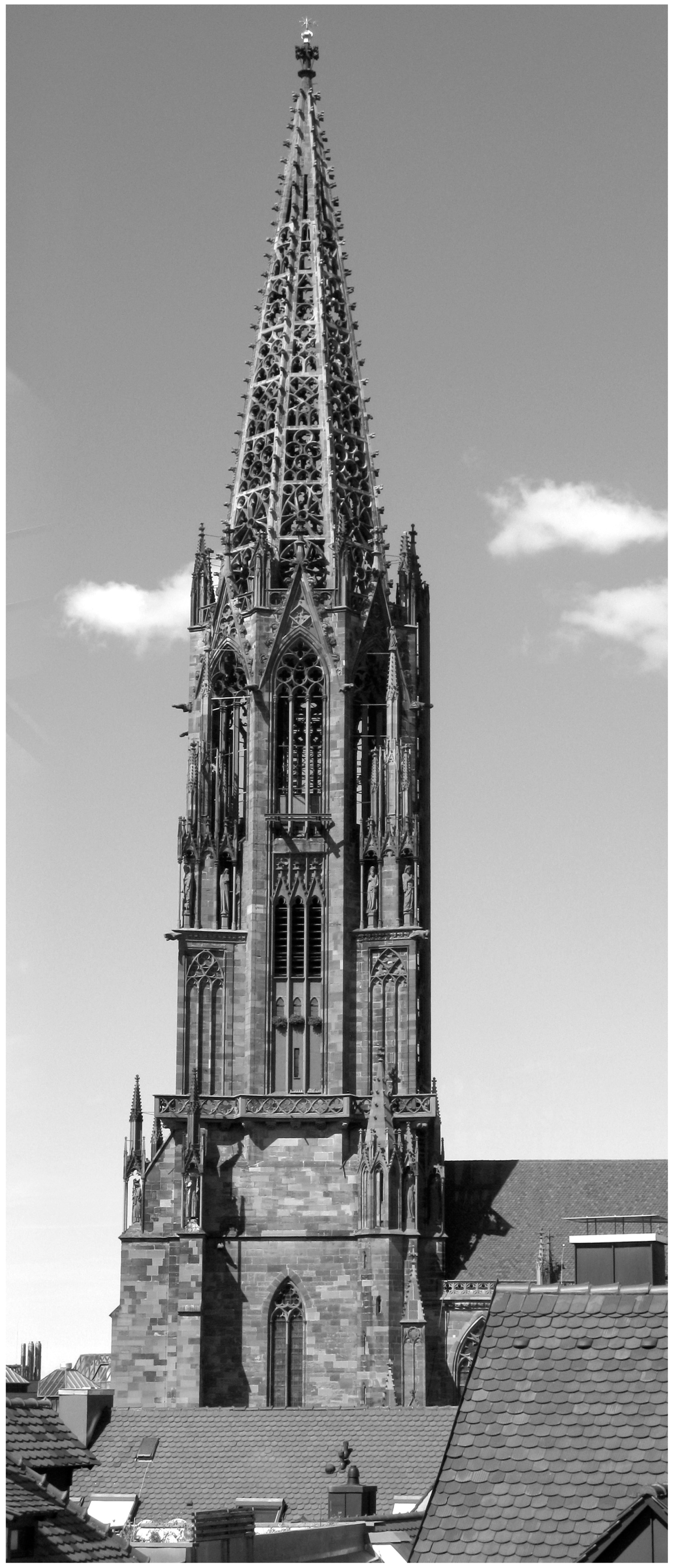
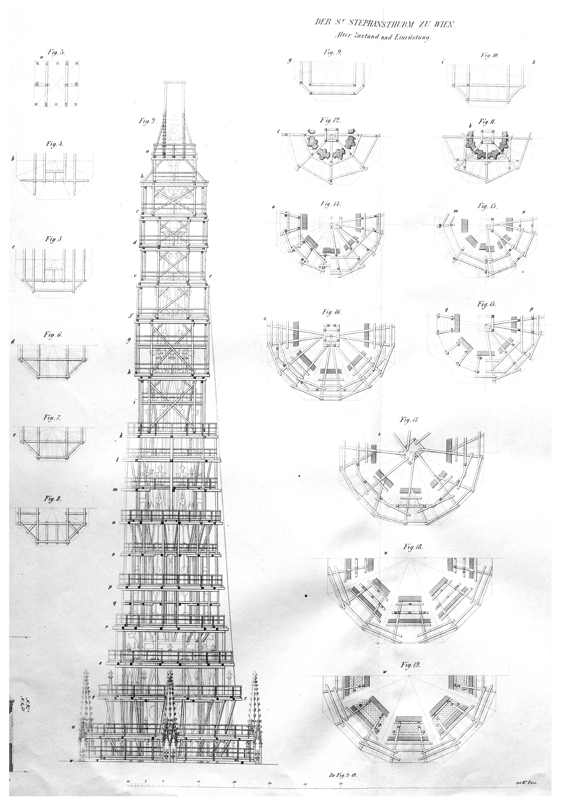
The golden age of the great spires was during the 14th and 15th centuries. Their most beautiful and most significant examples are on the territory of the former Holy Roman Empire. One spire in Freiburg (
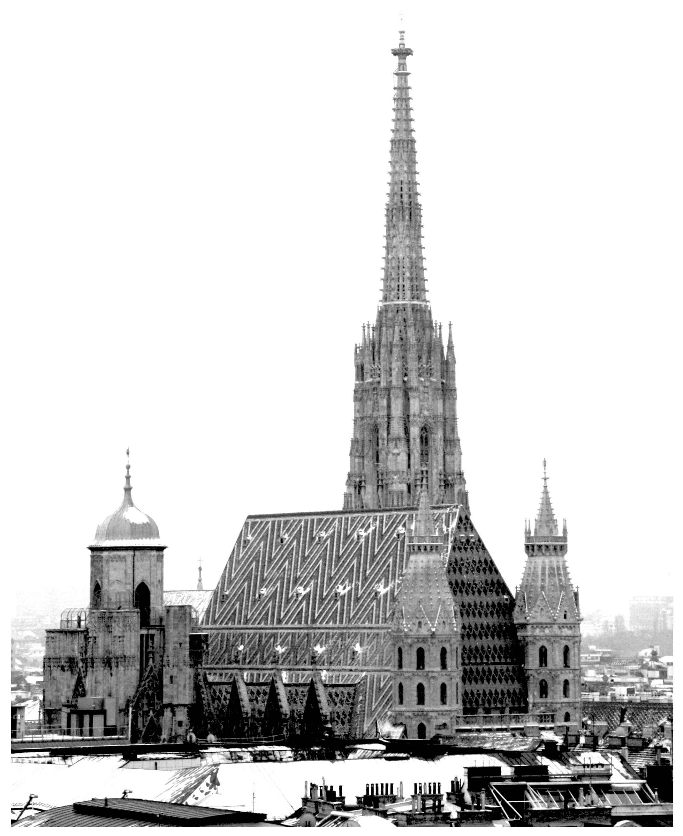
Figure 1), one in Strasbourg (Straßburg), and one in Vienna (
Figure 2) were completed during the Middle Ages. The spires of Cologne and Ulm were completed only in the 19th century, based on medieval plans. The tower of Prague and the second towers of Vienna and of Strasbourg remain uncompleted. Regarding the two latter, original plans of them have been preserved.
Discussing the question of the great spires from the technical side, it is important to mention that a church tower is a building element without any antique prototypes. The towers of antiquity were usually watchtowers and were either part of city fortifications or were freestanding, e.g., next to the limes by the Danube. Two important, legendary exceptions to ancient symbol-bearing tower-like structures are the Tower of Babel and the Pharos lighthouse [
9] (p. 8). The large number of medieval depictions of the construction of the Tower of Babel is also an important source of contemporary construction techniques [
11].
Since a tower is a freestanding structure, its construction differs largely from the construction of other building parts. This characteristic has special importance if we keep in mind that several researchers of the Gothic construction practice agree that the already completed building parts served as supports for the scaffolding and formwork. In the case of a freestanding, high, slender structure, there are not any adjacent building parts (walls, pillars) available that could be used as supports [
1] (p. 164), [
3] (p. 427), [
12] (p. 224). It is not by accident that the unfinished major tower constructions were usually suspended at the height of the main cornice of the nave. Discussing the structural behaviour of the Gothic churches, several authors came to the conclusion that, from the viewpoint of stability, the most important factor is not the quality of the building materials or the overall size, but the geometry [
13] (p. 22), [
14,
15]. This was already a known fact in the Middle Ages, but, of course, without any scientific background.
3 Summarised (and simplified), this means that a Gothic church could be safely scaled up to any level (of course just to some reasonable, but still very large, size), and it would still be stable if each of its parts were scaled up proportionally. There is only one significant exception: the tower. For towers, it is not only the geometry that matters. While, in the case of naves, the stability depends only on the proper geometry—the resulting stress in the stone cannot reach the limit—it is different in the case of towers.
The cause of this behaviour is a specific characteristic of the stone as a building material: its tensile strength is negligible compared to its compressive strength. According to Jacques Heyman, the theoretical maximum height at which a stone column would crush its base due to its own weight would be 2 km [
13] (p. 12). The highest medieval nave can be found in Beauvais; its height is 48 m [
17] (p. 463). This example illustrates that the crucial factor is not the compressive strength of the stone. The problem is that, due to their modest tensile strength, stone structures are not able to carry large moment. By choosing the right shape of the structure, it is possible to avoid tensile stresses; that is what proper geometry means.
The tallest medieval stone towers are 130 to 140 m high, not even close to the theoretical 2 km limit, but the practice is more complicated. First of all, a tower is much heavier than the naves of the Gothic era with their large windows, so more severe foundations are needed. Since the height of the tower is many times larger than its base area, the structure is much more endangered by uneven settling. Because of the large height and the lack of adjacent structures, supporting the horizontal load of the vaults and the spire is more problematic.
4 That is why the large openwork stone spires contain hidden metal reinforcing [
18] (p. 58), [
13] (p. 121), [
19] (p. 20), [
20] (pp. 272–273). Structurally, they are the early forerunners of reinforced concrete structures: the compressive forces are carried by the stone, while the tensile ones by the hidden metal parts. In addition to their dead load, the towers carry the significant imposed dynamic load of the bells. The wind is a dynamic load, too, and it can induce significant movement of the structure. In the case of a 130 m high tower, a 1% horizontal displacement of the top is equal to 130 cm. This could not be borne by a rigid stone structure. The solution is the application of a soft material in the joints: lead [
21].
Stone structures can easily handle fully vertical loads, but arched (e.g., vaults) or inclined (e.g., roofs, spires) structures induce horizontal loads too. The bearing of these forces is a crucial problem, running through the entire history of architecture. The closest the resulting force is to the vertical, and the smallest is the lateral component, meaning the problematic horizontal load. So, above a certain size, a slender tower is statically more appropriate than a wide one. Size matters because of the stability when carrying the wind load. The wind load depends on the cross-sectional surface of the tower (the elevation area), but the weight depends (and so the resistance against the wind load) on the volume. This can be illustrated in an example of a cube: if the side length of a cube is doubled, the area of a side surface plane will be four times bigger (the square of the side length), while the volume will be eight times bigger (the cube of the side length). In the case of a tower, the weight will increase significantly more than the elevation area only if the wall thickness is also scaled up parallel to the increase in height.
5 Contemporary sources testify that the Gothic practice was based on similar principles: in these manuscripts, the wall thickness of a tower depends on its height [
14] (p. 168). So, if a tower is considered a rigid structure, its stability is in relation to its height (it is more stable if it is higher) [
14] (p. 191). Summarising the above, the higher and slenderer the tower and the steeper its spire, the better it works structurally. As the comparison of the Freiburg tower (the first great spire) to the ca. 100-year-younger south tower of the Stephanskirche in Vienna proves, the direction of evolution was exactly like this [
22] (pp. 159–160). But the larger size, the slenderness, and the steeper spire made the construction process more difficult. The difficulty of the task can be observed in practice too; only a few great spires were completed in the Middle Ages. The three most significant are in Freiburg, Strasbourg, and Vienna. The “second line” consists of much smaller towers. The end of the Middle Ages marked the end of the era of great spires too; this form was extraneous in the Renaissance and Baroque periods. Similar structures were erected again only in the Gothic Revival period. The most significant ones (Ulm, Cologne) are the completions of medieval ones based on original plans.
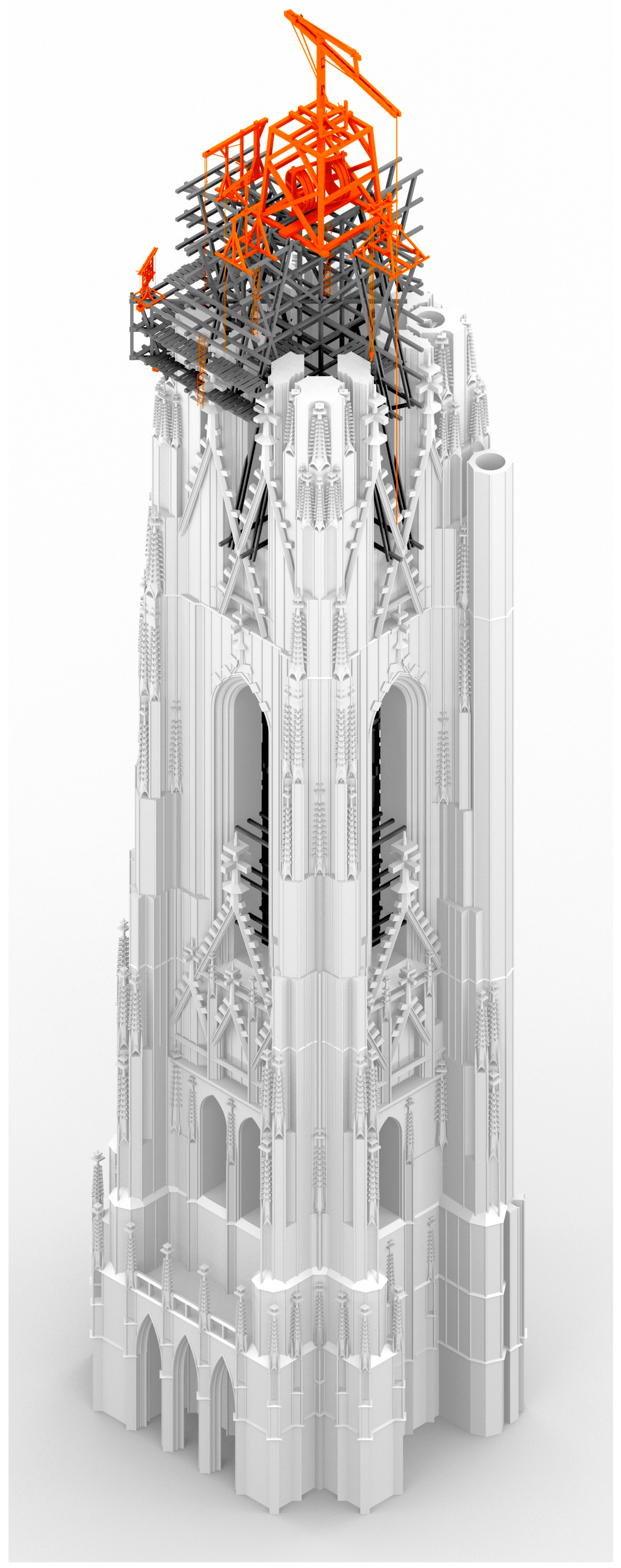
The most reassuring way to reconstruct a medieval construction site would be to conduct a life-size experiment: to construct the structures using the original plans and the technology available at that time. Since there is hardly an opportunity to achieve this, 3D modelling emerges as a solution. To reconstruct and illustrate the building process step by step, an unrealised structure was chosen for which original plans are preserved: the north tower of the Stephanskirche in Vienna. The reason for choosing an unrealised tower was to avoid any possible misunderstanding: the aim of this project was not to introduce how a particular tower was built, but how a tower could have been constructed using the instruments in the sources discussed.
It is important to emphasise—as is discussed in several papers written by Norbert Nußbaum [
23,
24,
25]—that the Gothic construction practice cannot be generalised. While forms could be spread on paper or parchment, the technical details and solutions could not. Norbert Nußbaum distinguishes the expressions ‘entwerfen’ and ‘planen’: the first means the invention of new forms, while the second is the application of new forms in practice on a particular building. The switch between the two induced a change in the medium (from parchment/paper to Reissbrett, a kind of drawing board), as well as a change in scale [
25] (pp. 284–285). The drawing series in this article is similar to the process of how a medieval master builder made preparations for the construction using the plans (planen), with the notable difference that this project focuses mainly on the auxiliary structures, not on the buildings themselves (of course this was the task of the medieval builder, too). So, not only can it not be stated that a particular tower was constructed this way, but it also cannot be stated that Gothic towers were generally constructed this way; the drawing series illustrates only a possible solution.
No similar, comprehensive series of drawings about a Gothic tower’s construction—illustrating not only the tower itself but also the auxiliary structures, based on historic sources—has been published yet in the literature.
6 The situation is different south of the Alps; on the construction of Brunelleschi’s dome for the Florence Cathedral (the most thoroughly researched construction site in the history of architecture), several similar drawing series are available,
7 not unrelated to the fact that a contemporary drawing collection also survived about Brunelleschi’s machines.
8 The intention of this project was to create the northern counterpart of the drawings describing the dome’s construction and, at the same time, to suggest that the construction of great Gothic spires was, albeit in a different nature, a similarly significant achievement in engineering. The parallel did not come out of thin air. According to recent literature, Brunelleschi’s dome can be considered an advancement of medieval technology rather than a reiteration of antique Vitruvian ideas within the context of Renaissance architecture [
30] (pp. 116–117).
The aim of this paper is to create and interpret a 3D visualisation of the theoretical construction process of a great Gothic spire, with each element grounded in contemporary or early modern sources. Since discussing these sources is integral to the topic, the first part of the paper will focus on that. Then, based on the discussed sources, 3D models are created to illustrate and interpret the building process and the way of using the devices from the sources.
2. Materials and Methods
To reach the goal, first, reliable sources had to be revealed that were suitable to provide information for the 3D models. During the construction of a tower, the scaffolding and machinery are the most important auxiliary structures, so for the reconstruction of a building process, three groups of sources are needed:
Architectural plans for a tower;
Drawings of machines used for tower construction;
Drawings of scaffolding used for tower construction.
In the first step, extensive research was conducted to find and review as many contemporary drawings in these categories as possible. The most suitable sources for the goal will be discussed in the following subchapters.
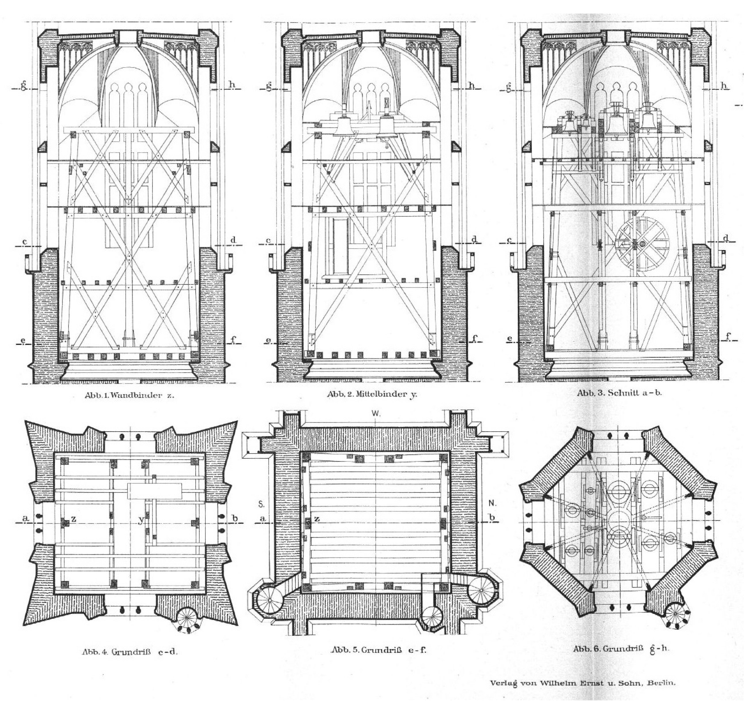
After selecting the appropriate sources, the 3D modelling began. The software of choice was Rhinoceros 3D version 5 by Robert McNeel & Associates. Due to the technical requirements of the project involving floor plans, elevations, etc., the software needed to operate in a sufficiently CAD-like manner compared to other popular 3D software (e.g., Blender, Maya, 3D Studio Max). Additionally, it was crucial for the software to provide high-level 3D functionality, accommodating complex geometries such as supporting real arcs instead of polygons (which some other software uses to emulate arcs), offering the possibility of sub-layers, enabling multiple instancing, and ensuring the high quality of the built-in renderer. The visualisation was divided into four stages, following the usual structure of a great spire: (1) tower base, (2) freestanding square-shaped part, (3) freestanding octagonal part, and (4) spire.
In general, the models were prepared as follows: for each phase, first, the building itself was modelled in 3D, based on the chosen medieval drawings (floor plan, elevation) until the given height; then, a possible scaffolding was prepared using the sources discussed later; and finally, the relevant machines were positioned at their proper locations, mostly based on the drawings of the Strasbourg master builder Hans Hammer.
The three types of contemporary sources required different approaches. The architectural drawings of the 15th century are similar to their modern counterparts in the key aspects: they use orthogonal projection, they are drawn precisely to a given scale, and the related drawings for a given structure (floor plans, elevations) are consistent with each other [
31] (pp. 15–52). One idiosyncratic characteristic of the Gothic floor plans is that the different levels (horizontal sections) are represented in one single drawing. The result of this method is high accuracy and consistency, and a single floor plan is enough to model the entire structure if the related elevation is also available. So, first, the two chosen drawings were imported into Rhino 3D as pixel drawings (the floor plan into the top view and the elevation into the front view) and set to the appropriate scale. For the dimensions of the actual north tower, a scaled drawing by Böker was used, where the medieval drawing is combined with the actual floor plan of the existing building [
32] Taf. 1.
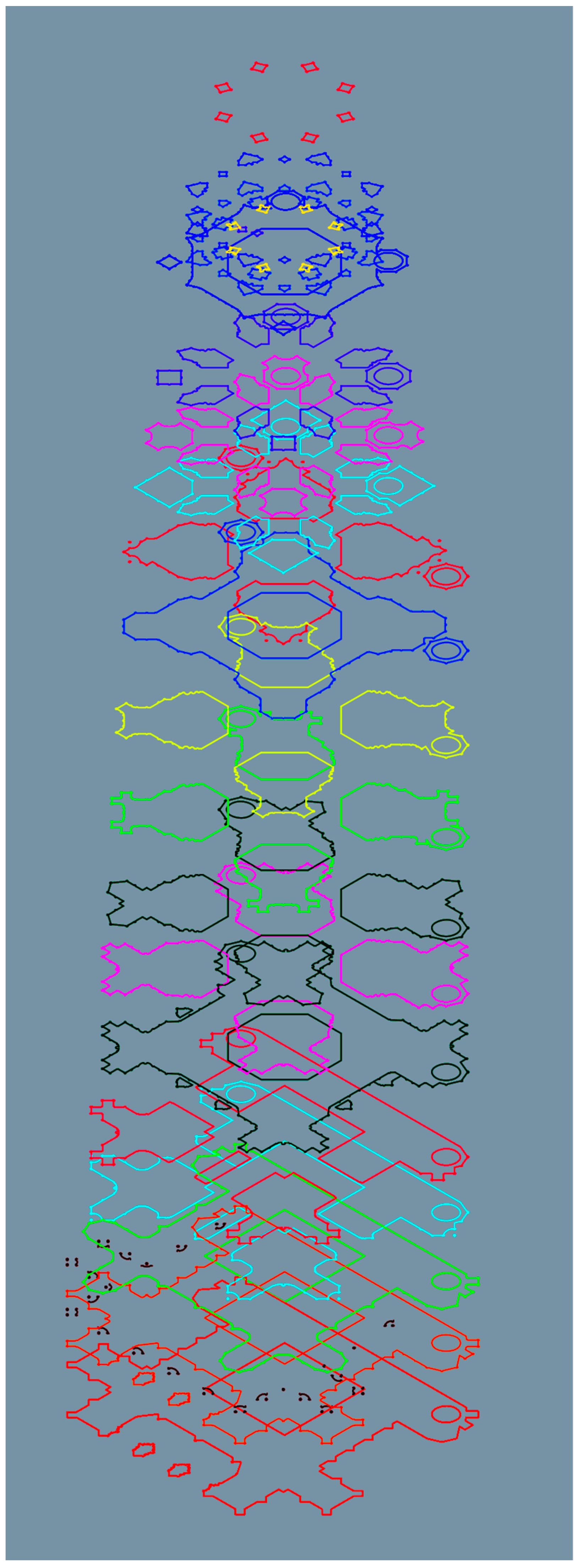
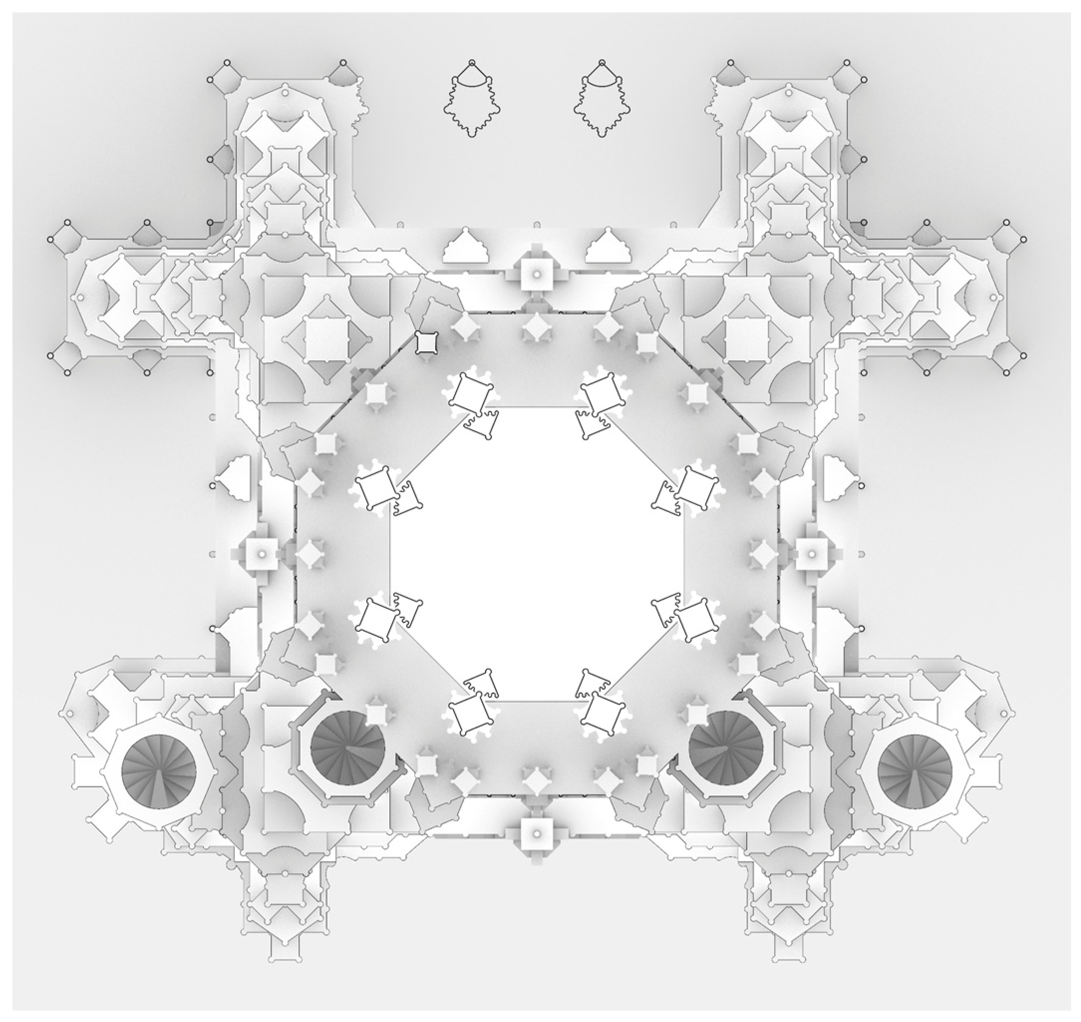
In the second step, in the floor plan, the contours for the different levels had to be separated and redrawn (
Figure 3). Due to the tapering nature of the structure, the outermost contour belongs to the bottom level; counting from the outside in, the second belongs to the second level, and so on. Then, these levels had to be identified on the related elevation drawing, and based on that, elevated to their appropriate height (
Figure 4). In the next step, the curves were vertically extruded until the base of the next level.
This way, the basic framework of the structure is defined.
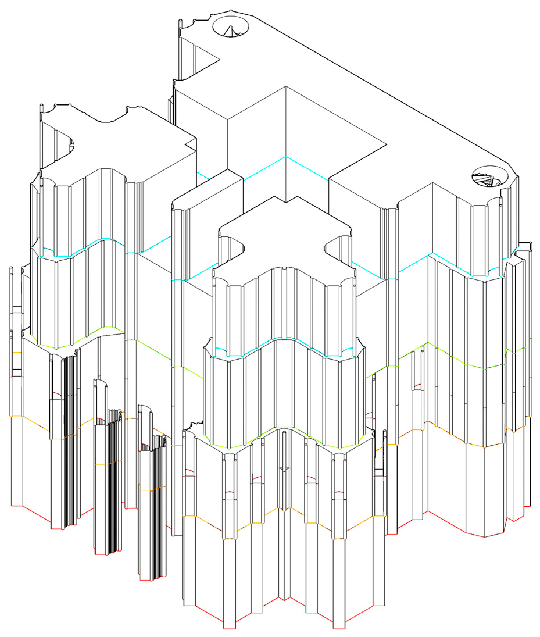
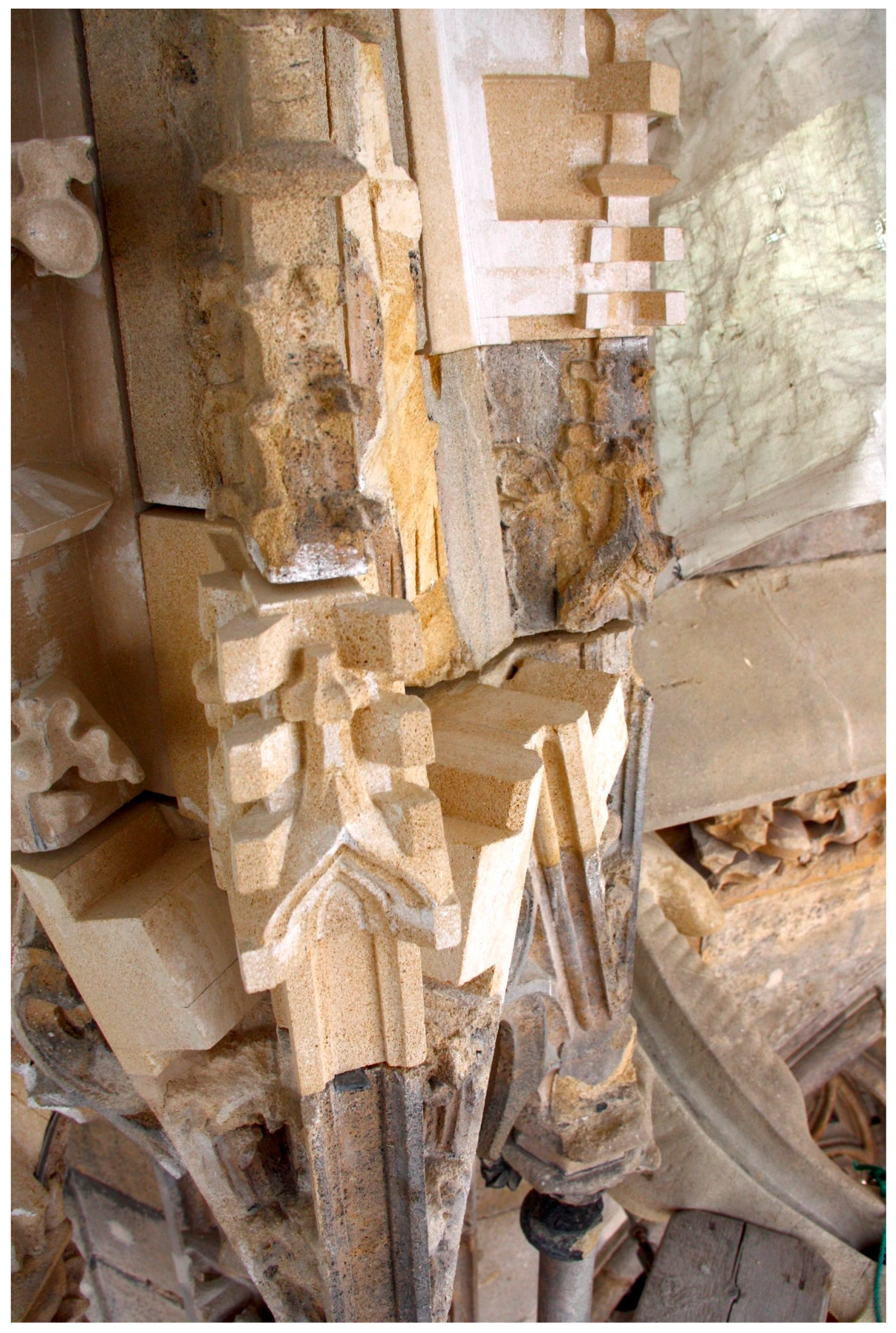
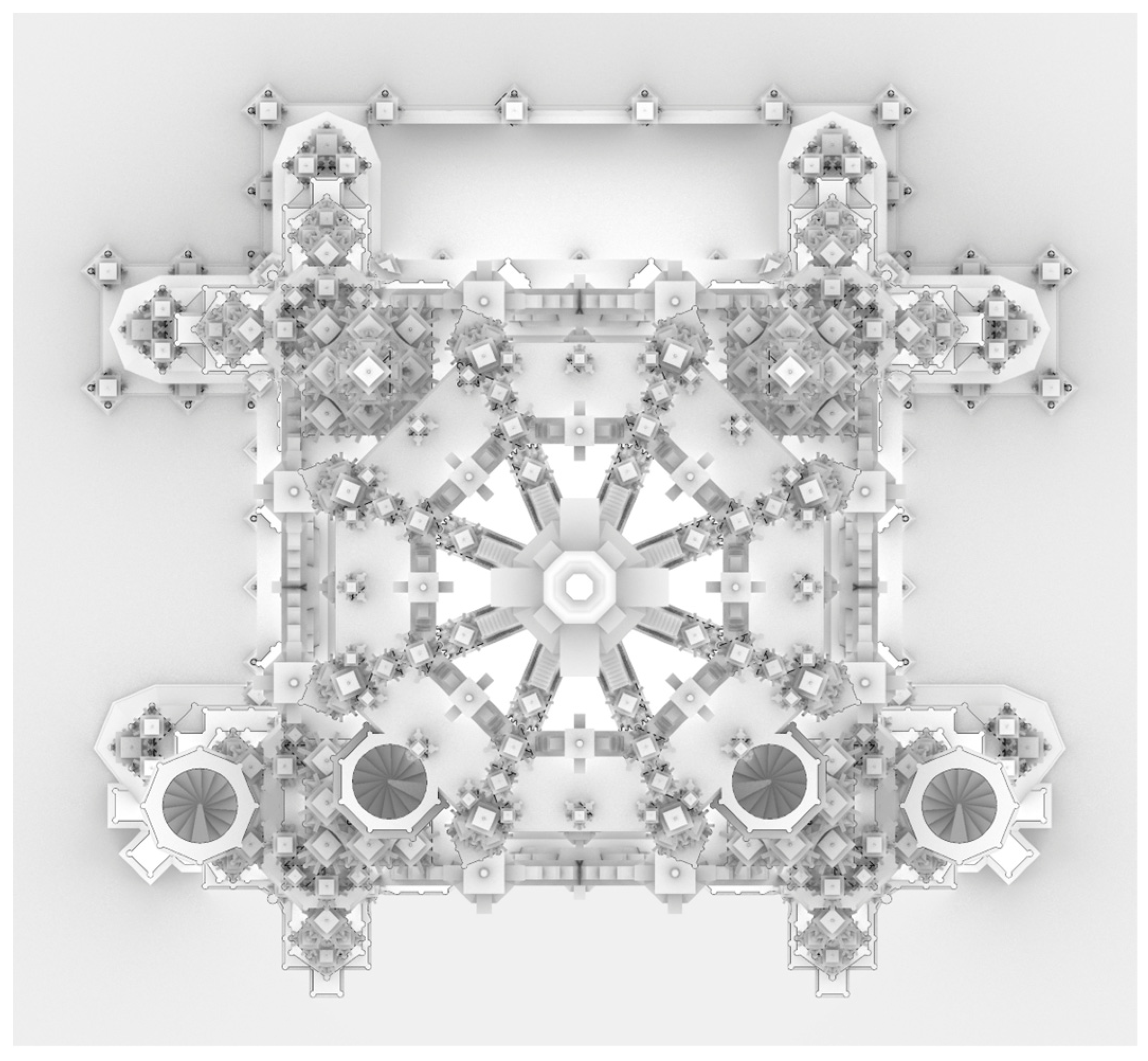
Figure 5 illustrates an intermediate stage, where only the extruded contours are present up to the sixth contour. In the next step, the architectural elements not presented on the floor plan (cornices, gables, and pinnacles) are modelled using the elevation drawing. The modelled geometry is simplified compared to the elevation drawing. In medieval stonemasonry, at first, the geometrical base shape of the ornaments (finials, crockets) was carved. Matthäus Roriczer’s booklet about the construction of a pinnacle is a contemporary source representing this method [
33], and stone masons working on the maintenance of Gothic structures work the same way even nowadays (
Figure 6). In the model, the structure is displayed at this stage. Another simplification is that traceries (as they are secondary structures) are not shown.
The resulting geometry can be seen in
Figure 7. It is a shaded, orthogonal top view of the model, and only the elements are displayed that are present on the floor plan drawing, so it can be compared to
Figure 3. For comparison, in
Figure 8, the elements are also displayed that were modelled using the elevation drawing (cornices, gables, pinnacles).
In the case of the scaffolds, the sources could not be adapted unchanged due to the nature of these structures. Here, some kind of design work was needed: the solutions learned from the sources had to be adapted for the given structure. For this, the structural and operational logic of contemporary structures had to be understood.
Some kind of interpretation was needed in the case of the machine drawings too, due to their contemporary conventions. According to McGee [
34] and Leng [
35], this representational style has the following main characteristics:
The drawings have no scale; the final size of the machines was determined during their construction. To understand the drawings, the context of their construction is needed;
One drawing for one machine. There are no different views about the same machine;
Only one, usually elevated viewpoint. The perspective is distorted when it is necessary for the understanding of some parts.
This means that these drawings cannot be simply imported into Rhino and then redrawn. The modelling process here is similar to creating a 3D model based on a single photo. The scale is also problematic, both in relative and absolute terms; sometimes, the different parts are not drawn to scale in the modern sense, as will be discussed below. Identifying the appropriate general scale (size) of the machines is also difficult; usually, the size of the drive winch and the approximate cross-section size of the timber parts can provide hints, but a precise absolute scale for these devices is not applicable, as it will be discussed later.
2.1. Sources Used for the Visualisation
As mentioned above, three groups of sources were needed: (1) architectural plans of a tower, (2) drawings of construction machines, and (3) drawings of scaffoldings.
Fortunately, in the first group, many contemporary drawings survived; there are thousands of architectural plans available from the Gothic period.
9 Since these drawings are popular, well-researched subjects, even 3D models can be created using them [
40,
41]. In this paper, only the main statements of the relevant literature will be briefly introduced regarding the chosen structure (Stephanskirche, Vienna, north tower).
The second group (machine drawings) is different. Compared to the relatively high number of preserved warfare-related illustrated manuscripts [
43], the representation of machines for civil usage in the Middle Ages is very rare, and in contrast to the architectural drawings, the majority of them are unpublished. It is very important for the subject of this paper that the portfolio of Hans Hammer, who was the master builder of the Strasbourg Cathedral at the end of the 15th century, survived,
10 and it includes many machine drawings. When these drawings were created, the north tower in Vienna was under construction.
The situation of the third group (scaffoldings) is the most difficult. Although scaffoldings are technically very challenging auxiliary structures, there are no contemporary plans or technical drawings of them preserved. So, representations from the fine arts and the few preserved scaffoldings had to be used. These are quite rare but very informative and valuable sources. They were able to survive because they were not external scaffoldings (as is usual nowadays), but were situated inside the towers.
Although the first technical drawings of tower scaffoldings date only from the 19th century, it is important to discuss them. Between the Gothic and the Gothic Revival eras, builders did not have to face the challenge of constructing large-scale, intricate, carved stone towers. Similar technical problems require similar solutions even when several centuries have passed, and all the more if the technical problem did not exist in the period inbetween.
11 This assumption is supported by Viollet-le-Duc as well, regarding machines. According to the fifth volume of his dictionary (published in 1861), only the previous two decades brought significant improvements in the field of construction machines; until that time, the machines were the same as in the 13th century [
48] (p. 218).
The example of the scaffoldings illustrates very well how challenging the work on the Gothic and Neo-Gothic towers was in the 19th century. There were no such high scaffoldings erected since the Middle Ages as in the Gothic Revival era [
49] (p. 231). The dismantling and then the reconstruction of the upper parts of the Viennese south tower between 1838 and 1842 generated so much interest that a detailed article was published in the journal
Allgemeine Bauzeitung about the scaffolding used [
50]. A few decades later, due to the completion of the Cologne Cathedral, the carpenters of the scaffoldings were more celebrated than the stonemasons [
51] (p. 158). The photographs of the scaffoldings were published abroad [
51] (p. 134), and professionals arrived even from America to see them [
49] (p. 79), [
52] (II, p. 273).
2.1.1. The Plans for the Viennese North Tower
According to the Dehio-Handbuch, the construction of the north tower in Vienna started in 1450 under the leadership of Hans Puchsbaum and stopped above the interlocking gables in 1511, when the master builder was Anton Pilgram [
53] (pp. 182–183) (
Figure 2, to the left).
The first catalogue of the Gothic plans of Vienna lists 18 drawings related to this structure [
38] (p. 3). For the present project, the complete ones (displaying the whole structure) are the most important. These are the following: floor plans: 105.063, 16.872v, 105.064; elevations: 105.067, 17.061, 105.062. Examining the level of detail and consistency, for this project, drawings 105.067 (elevation)
12 and 105.064 (floor plan)
13 were chosen. Both of them are owned by the Wien Museum Karlsplatz.
According to Hans Koepf (editor/compiler of the first catalogue), two main questions emerge about these drawings: why did their creators put so much effort into a task to which a solution was available in the shape of the completed south tower; and who were the masters who drew the plans [
38] (pp. 3–4)? He answers the first question immediately: in the Middle Ages, the builders never copied an existing structure. The more time passes between the two constructions, the greater the differences. He cites the north tower of the Strasbourg Cathedral and Hans Hammer’s later tower plan as an example as well as the two towers of the Münster in Basel. With a few exceptions, he did not name any possible authors for the drawings and only identified the drawings relating to each other.
According to the second comprehensive catalogue of the Viennese drawings [
31], drawing 105.064 is the completed and finalised version of the earlier 105.063 drawing, which was made by Laurenz Spenning around 1465. The 105.064 was probably made by Georg Hauser in 1516 [
31] (pp. 421, 424–425). Drawing 105.067 was the work of Laurenz Spenning, and it closely follows the levels of the south tower and is very similar to the constructed parts of the north tower. It corrects the unevenness, which is the result of the continuous changes in the plans for the south tower, so it can be considered the actualised and integrated reconstruction of the south tower [
31] (pp. 435–443).
According to a theory of Böker, Hans Hammer might have been involved in the construction of the north tower [
54,
55] (pp. 204–205), [
56] (p. 274), [
57] (p. 48), [
41] (p. 153). This theory cannot be proven, although the portfolio of the master informs us that Hans Hammer visited Vienna in 1478 and recorded one dimension of one tower.
14 2.1.2. The Machinery of Hans Hammer
Hans Hammer was active at the turn of the 15th and 16th centuries.
15 Luckily, a number of his drawings have been preserved as originals: out of the 34 pages of his portfolio, 29 pages still exist, and some of his other drawings are kept at the Musée de l’Œuvre Notre-Dame in Strasbourg (Frauenhaus). This manuscript corpus is excellent for examining Gothic construction since the range of drawings extends from absolutely fictitious sketches through preliminary designs of specific buildings all the way to fully detailed plans. With regards to the construction, there are a number of drawings made of construction machines and instruments too. Furthermore, Hans Hammer was twice the master builder of the church that has the highest and most admired Gothic tower. Even though he himself did not build any towers, he made a detailed plan for the south tower in Strasbourg that was never realised, and many of the drawings in the portfolio can be connected to the plans of the tower [
61].
His portfolio is owned by the Herzog August Bibliothek in Wolfenbüttel (Germany).
16 The earliest date in the portfolio is 1476, and the latest is 1507. Of course, this does not mean that it was used by the master builder exactly from 1476 to 1507. The sheets include a modern numbering written in pencil in the upper-right corner of the pages. This numbering is used in the majority of the related literature, and it will be used in this paper too.
The significance of the portfolio lies in the following.
It is from a single author.
Its author is a known and significant person (he was twice the head of the supreme lodge), a large amount of data has survived regarding him, some other drawings of him are also preserved, and his preserved architectural works are known.
A number of drawings (and texts) can be linked to particular buildings.
In addition to the drawings with the expected architectural topics, there are drawings in the collection that are typical of military technology manuscripts of the age (machinery, ladders, instruments).
It has a textual part too, and thus it fits into the category of the rare tractate-type medieval architecture books.
17Except for five missing pages, it has survived almost in its entirety.
The Hungarian–German vocabulary at the end of the portfolio is an important linguistic record.
The portfolio is especially valuable from the perspective of the present paper because a number of hints indicate that Hans Hammer wanted to build the south tower of the Strasbourg cathedral [
59] (p. 185), [
45] (p. 127), [
61]. One of the most important arguments supporting the idea that the master had the intention to construct the tower is the large number of machinery drawings in the portfolio. The cathedral does not have any part attributed to Hans Hammer that needed the use of such machinery; it is obvious that there is no need for machinery in order to build a pulpit, sacrament house, small treasury, or small side chapel (in the works clearly attributed to Hans Hammer) [
58] (pp. 519–520), but these devices are needed when constructing a huge tower.
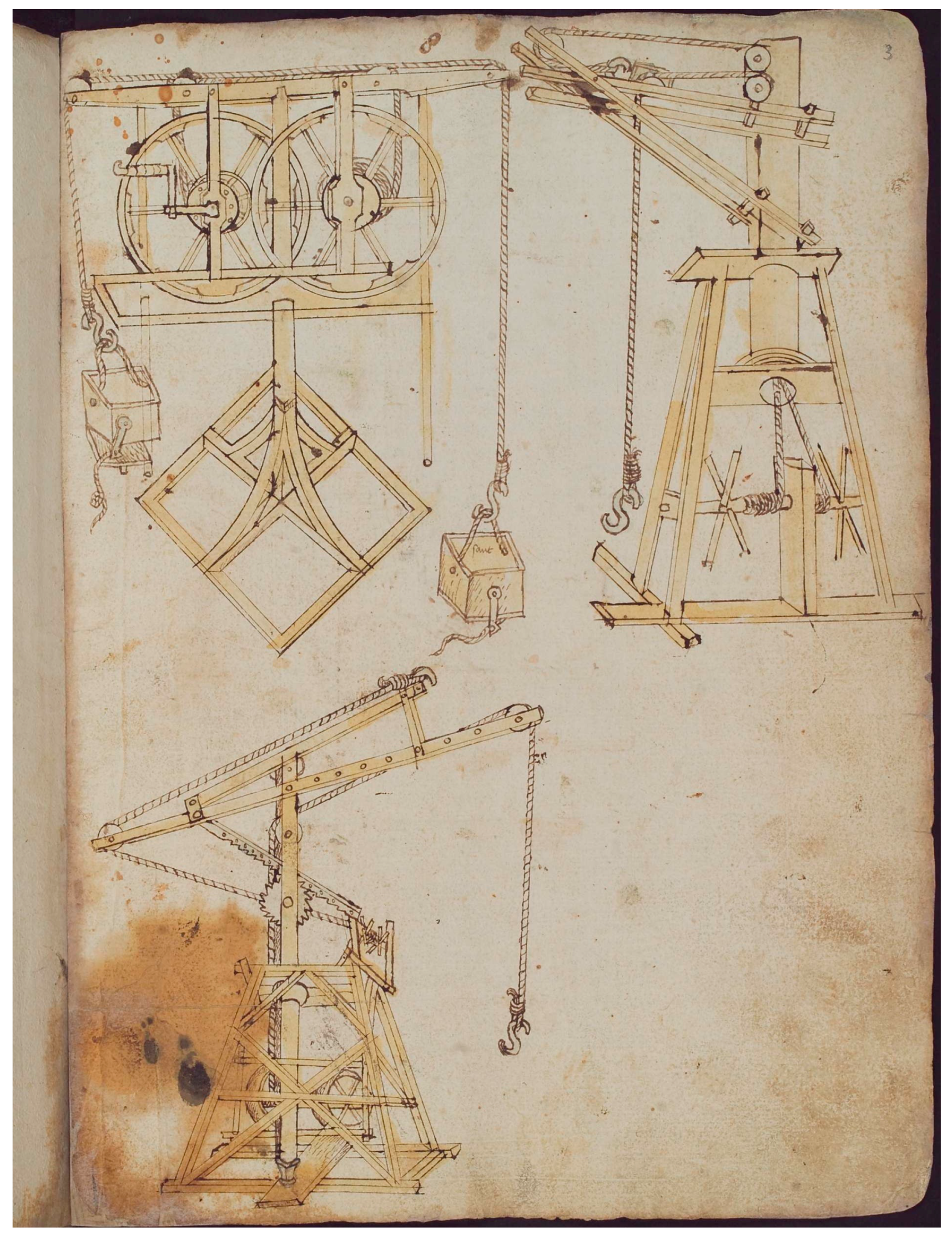
Nineteen machines are presented in Hans Hammer’s portfolio on nine pages, without any written commentary except for one case. The drawings are at the beginning of the portfolio, following four text pages, but these do not mention machinery at all.
Based on their operation, the machines of Hans Hammer can be divided into two main groups: frame hoists (for example,
Figure 9, top right, bottom left, bottom right) and cantilever cranes (for example,
Figure 9, top left;
Figure 10, top right, bottom). A third group is formed of a few machines that cannot be categorised into the two main types. The fourth drawing group of devices is the ladders.
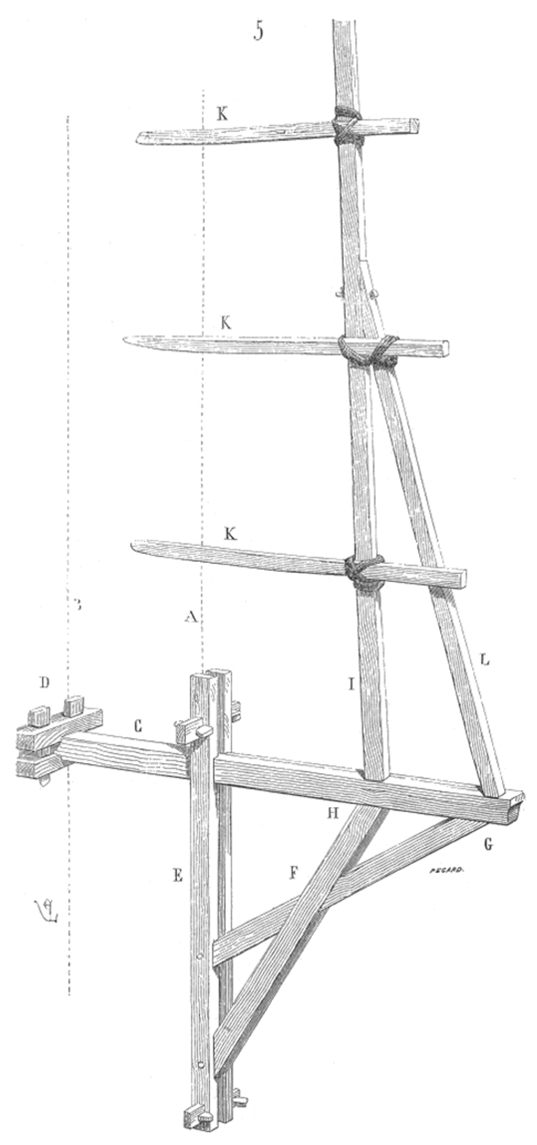
18 The Main Parts of the Machines
Based on contemporary representations,
19 a medieval crane consists of the following main parts (the same elements are present in Hans Hammer’s work too):
Frame Hoists
Eight frame hoist drawings can be found in Hans Hammer’s portfolio.
These structures usually consist of a frame shaped like an upside-down V and a rope that is attached to the middle and hangs down (for example,
Figure 9, top right, bottom left). It is not possible to position the load horizontally.
The drives are always winches with levers (the levers themselves are not drawn in some cases), of which they use either one or two. Levers are positioned at both sides of the axle of the winch in all cases, which means that either two or four people handled the machines.
All frame hoists (even the simplest ones) have block and tackle transmissions. This (and the fact that a number of people were needed to handle them) supports the argument that these were designed to lift heavy loads. Three of them (10r 2, 10r 3, 10v 1) have a structure with a ratchet to eliminate rolling back (these are not present in the case of the cantilever cranes at all). In the case of drawing 4r 4 (
Figure 9, bottom right), the drive is separated from the crane frame. In this case, the winch was either on the ground or on a lower level, while the frame itself was at the given height. A number of contemporary representations contain similar setups [
63] (p. 83), [
66] (p. 571).
The preserved contemporary military technology drawings often show frame cranes as cannon hoists. These were probably used on construction sites as well to load heavy stones on carts on ground level or to unload them, for instance, to unload the raw stone blocks arriving from the quarry. The Spiezer Bilderchronik shows a machine very similar to Hans Hammer’s machines at the work site of ashlar hewing workers (Steinhauers) [
67] (p. 204). In Strasbourg, but at other places as well, a stonemason workshop might have been set up somewhere in the heights (in Strasbourg, the so-called Wächter—on the top of the facade, at the foot of the tower—is ideal for this). In this case, construction work could have been sped up significantly if the large stones were first lifted to this level using a frame hoist with ratchet and transmission, then cut into parts and carved in this workshop, and from this point, lifted to their final location using cantilever cranes with smaller load-bearing capacities but suitable to position the load horizontally. In this case, the frame hoist was probably set up at the top of an inner scaffolding, and the large stones were lifted in through the middle opening in the vaults in the levels underneath (these openings are present both in Vienna and in Strasbourg). A number of medieval drawings show a rope running inside the tower [
63] (pp. 31, 44, 51, 57, 87, 100 (frame hoist with winch), 147 (frame hoist), 187, 191, 210 (frame hoist).
The two types of application of these machines (on the ground or at a height) can be deducted from the height to which the cranes can lift a load. The cranes 4r 3 (
Figure 9, top right) and 10v 1 can lift to a moderate height; 4r 4 (
Figure 9, bottom left), 4r 5 (
Figure 9, bottom right;
Figure 11), 4v 1 (
Figure 12), 4v 4, and 10r 2 can lift to greater heights.
Their further use might be to lift the bell into place. There are a number of examples in medieval sources for this type of use. On page 60v of Johannes Fromschneider’s military book from the middle of the 15th century, a frame hoist is displayed in the process of lifting a cannon, but the text next to it mentions a bell too [
35] (p. 96), and a bell is being lifted using a frame crane in a drawing of a manuscript from the 15th century, now kept in Vienna.
Cantilever Cranes
Eight cantilever crane drawings can be found in Hans Hammer’s portfolio. Their structure is as follows: a vertical crane post is protruding from a timber scaffolding, with a crane boom joining it (horizontally or obliquely). The frame itself is rolling on wheels on crane 4r 1 (
Figure 9, top left;
Figure 13). The crane post can be rotated in each case. Two drawings show a hollow crane post, with ropes running in the middle of it: 3r 2 (
Figure 10, top right) and 3v. The angle of the boom can be adjusted in most cases, either by using a second winch or by using a ladder-like auxiliary boom. A crane trolley that can be moved with rope is also shown in one of the drawings (3r 2,
Figure 10, top right).
The drive is always a winch with a lever, even in the case of the cantilever cranes, with one exception. The sole exception (3r 3) shows a pair of treadwheels with slightly distorted proportions (
Figure 10, below). The diameter of an average treadwheel used to be 4.5 to 5 m (based on the preserved examples) [
66] (p. 524). According to this measurement, the relevant crane would be 30 m high. But this is not necessarily a drawing error. Contemporary machine drawings were not made to scale, and their purpose was not the proportional representation of the object. It was more important to present the principles and to show the relationships between the elements and the details that were important from the point of view of their operation [
34] (p. 59), [
35] (p. 96). The already mentioned hoist drawing of Forschneider shows the transmissions and the pulleys out of proportion: they are too large [
35] (p. 96). It was probably more important for Hans Hammer to emphasise and make a detailed drawing of the new kind of rack and pinion solution fixing the angle of the crane boom instead of showing the treadwheel, which is, in reality, much larger but was already well known at the time.
Figure 14 displays the 3D model based on Hans Hammer’s drawing but with realistic proportions.
In the case of cantilever cranes, the horizontal positioning of the load is usually performed using a rotating crane post (often on a metal bushing) and an adjustable angle boom. These cranes were definitely used to lift lighter loads. This is supported not only by the fact that the boom has a smaller load-bearing capacity but also because most of them have no transmissions of any kind; the pulleys shown are there only to guide the rope (in drawing 9r, there are no less than five of them). The absence of ratchets also indicates lighter loads.
These cranes probably operated at great heights by being fastened to the scaffolding and used to lift the smaller, carved stones into place. The frequent occurrence of the vertical axle winch, which is otherwise rare in the so-called German school, also indicates its use on scaffolding, claims Tissot [
46] (p. 70). A contemporary representation also supports the theory that machinery fastened to scaffolding was used in medieval times in tower constructions.
20A special example of Hans Hammer’s cantilever cranes is a double crane with two posts and two booms (3v). It might be a fictitious structure since the position and fastening of one of the posts are not clear. Tissot assumes that this crane was used while fastened to a scaffolding, based on the fact that the method of drive is not shown: the ropes are simply hanging off of the bottom of the crane [
46] (p. 62).
Other Machinery
Cranes similar to the ones categorised into the two main groups above are well known from other contemporary representations. Two machine drawings of the portfolio seem to be completely unique.
Machine 3r 1 is a structure with a crank handle and flywheel, with a reducing transmission, counterweight, and arched legs (
Figure 10, top left;
Figure 15). Both the crank and the arched legs indicate southern connections; these are rarely found in representations created north of the Alps, but in Italy, they are common [
66] (p. 519).
21 The wheel driven by the crank handle drives another, much larger wheel; the load rope is wound onto the shaft of the latter one. At the same time, a rope is running on the shaft of the crank, and at the end of it, there is a box on the drawing; the bottom of the box can be opened, and it is marked “sand”. This is probably a counterweight.
22 A similar sand box, clearly used as a counterweight, is shown on a drawing from around 1450.
23 Due to its transmission, this machine was capable of lifting loads about three times as heavy as the counterweight and doing so without any serious effort. But the routing of the rope is incorrect. The machine obviously operates only if it uses alternating motion: when one of the ropes is moving up, the other one is moving down. But the ropes are marked differently on the drawing; this must be a drawing error. Such drawing errors can be found elsewhere as well, but these were possible to correct during the construction by experts.
This machine is special also because it employs a double flywheel, and this feature is absent in the other known contemporary machine drawings. The structure most similar to this one found in contemporary representations is an image of a torturing device, also employing crank handles, in the altar painting of the Neustift Church in Tirol made in the 1480s [
70] (p. 531).
The other unique machine (4v 2) consists of a frame fastened to a vertical cylinder and a metal block and tackle system (Flaschenzug). This is probably a small, one-person-operated lifting device that can be fastened to an existing building structure (to the wall/pillar). Tissot supposes that the cylinder is hollow, so the structure can be impaled on any existing vertical pole (for instance, a crane post or scaffolding element), so it could be used on a construction site at many locations with many copies [
46] (p. 147). Notable is the removable metal handle, which ensures that, by removing it, no unauthorised person can move the machine.
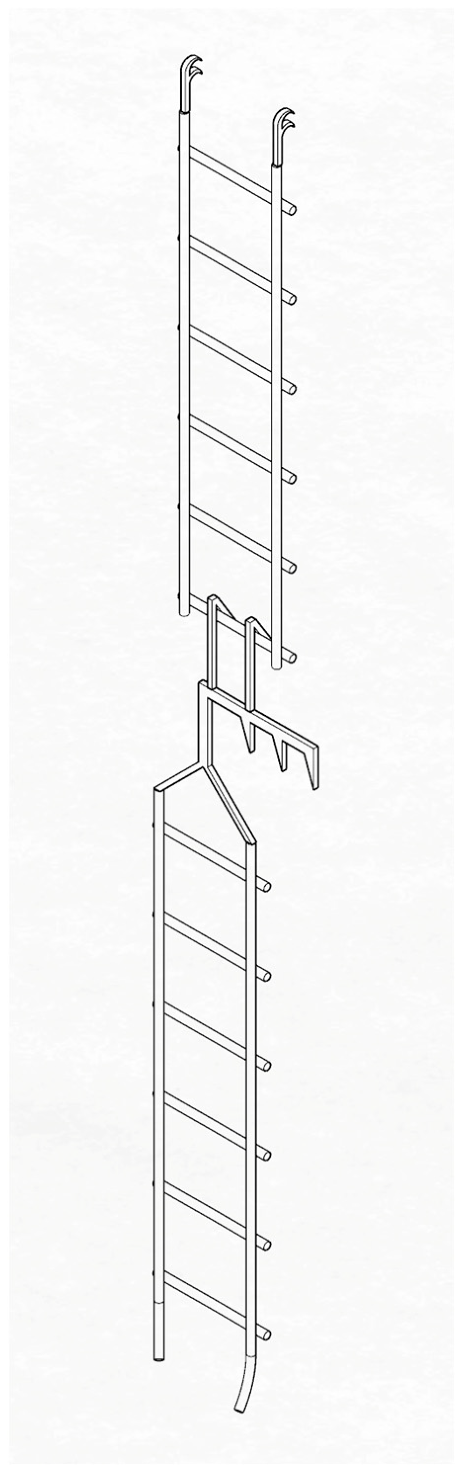
Ladders
The drawings of various ingenious hooked ladders are in one block with the drawings of machines. In addition to rigid ladders, there are also rope ladders and ladders made of straps. A number of them are combined with pulleys, and the majority of them are modular (
Figure 16). There are similar ladder representations among the drawings of contemporary military technology as siege devices.
24Since Hans Hammer was a master builder and not a military engineer (by that time the two professions were separated [
72]), it is almost certain that Hans Hammer’s ladders were not siege ladders but served to provide access to the different levels of the scaffolding of the cathedral and, in general, to provide access for working on the building. As a master builder, it was probably one of his duties to continuously supervise the condition of the building. It is known from contemporary sources that it was one of his tasks to renovate the angel on top of the south tower [
60] (p. 276). It is possible that locations that were hard to access were reachable using these ladders, either for him or for his workers.
2.1.3. Scaffolds
There are two main types of construction scaffolding: centre scaffolds and work scaffolds [
47] (p. 18). The first type served to define the shape of the building structure and provide temporary support during the construction, similar to modern formwork; the latter type is for carrying out work. Usually, the two functions can be clearly distinguished, but the tower spire is a very special structure; it is possible that here the same scaffold served both functions, at least partly.
Unfortunately, there are no technical drawings available from medieval times about scaffolds [
47] (p. 22). Because of that, the artistic representations showing constructions are especially valuable. These were collected at the University of Cologne into catalogues [
63,
65]. Günther Binding’s study about scaffolding in the catalogue from 1978 provides a very good overview [
65] (pp. 58–61), so its main statements will be summarised in the next paragraph.
The two main scaffolding types were cantilever scaffolds (Auslegergerüst) and rod scaffolding (Stangengerüst). The first one was already present in representations in the second half of the 12th century, while the latter one only appeared in the 1380s, but from then on, it is similarly frequent as the cantilever scaffolds. The work areas were usually approached using ramps or, more often, ladders. In the case of cantilever scaffolds, the walk platform is laid out on horizontal cantilevers, which are laid on the top of the wall, built into it, and supported by angle braces underneath. There are representations from the end of the 15th century that depict scaffolds where the upper levels are laid on the surface of the lower scaffold and are reinforced using saltires. Rod scaffoldings are more and more frequent in representations following their first appearance (in the 1380s). The rods (legs) were usually set up about 1–1.5 m away from the wall. From the middle of the 15th century, horizontal longitudinal rods (Streichstange) appear fastened perpendicularly to the poles with ropes. Cross-beams of 8–13 cm thick (also called crossbars, Netz- oder Rüstriegeln) were fastened to longitudinal rods and the wall, and on top, the walk platforms were laid (Laufboden, Flechtwerk). A representation from the end of the 15th century shows a scaffolding in connection with a tower construction that is so advanced
25 that its type remained in use until the 19th century. The representation shows how the scaffolding, supported on columns, encircles the entire tower. Every second vertical rod is cross-strutted on all sides. The longitudinal rods are fastened to the vertical rods using ropes or straps. The walk platform is made of planks, which are laid on top of the cross-beams. An exception is the solution where a second vertical rod system is installed right in front of the wall (meaning that the cross-beams are not lying against the wall); this can be seen in a representation from the middle of the 15th century.
26A number of authors agree that scaffoldings used in medieval times were work scaffolds only and were not used as temporary storage for building materials [
48] (p. 104), [
73] (p. 117), [
74] (p. 220). One of the reasons for this could be that heavy scaffolding, suitable for storing stone, requires much more timber to build, and they tried to solve the matter of scaffolding (among other things) economically. Accordingly, the entire building was probably not scaffolded fully, starting from the ground, but the scaffolding was moved around as the construction work progressed [
73] (p. 117).
The surviving scaffold holes in buildings provide important information about the size of the scaffolds. In the case of cantilever scaffolds, the cantilevers themselves were built into the scaffold holes; in the case of rod scaffoldings, the ends of the cross-beams were inserted. As per the observations of Phelps and Lacroix, the vertical distance of the hole sequences in the case of cantilever scaffolds is usually 1.20 to 1.30 m [
75] (p. 114), [
74] (p. 218). The reason for such a small distance could be that it provided fairly easy access to build the next level of scaffolding while standing on the existing top level [
75] (p. 114).
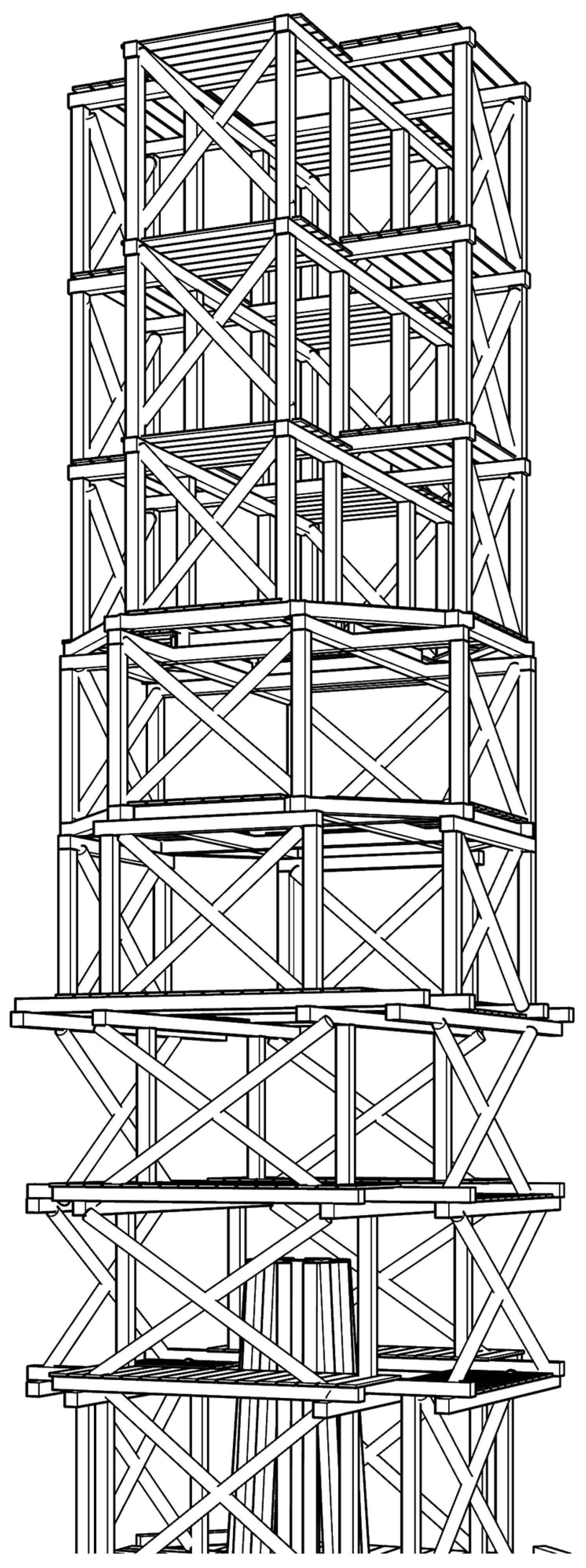
Bechtold publishes the specific dimensions that became common during those times [
47] (p. 22). According to these, the scaffold posts stood about 3 m apart, next to one another. If a post was extended, the overlapping part had to be 2 m long, and the parts were fastened to each other using hemp rope. An end-board running at a height of about 30 cm and a railing at a height of 80 cm are also mentioned in his article.
Based on the literature summarised above, it seems that, in late medieval times, scaffolding with posts was probably in use in the case of large-scale constructions since it has a number of advantages when compared to cantilever scaffolds. The hole sequence of the cantilever scaffolds indicates that work was performed only on a single level at a time. The process of building was probably the following: when the wall top reached a height of 1.20 to 1.30 m from the current work level, which was still easily accessible, the next series of cantilevers were placed on the top of the wall, and on top of them, the stones that provided a superimposed load. Next, the planks were placed on top of the cantilevers; from this moment on, the lower level became unusable. The planks of the upper work level were probably put directly in place during the removal of planks from the lower work level. But, in the case of the scaffolding with posts, the work levels were further away from each other, so fewer work levels were needed; also, work could have been carried out on multiple levels at the same time. The increase in the volume of timber needed due to the posts could have been compensated for since the cross-beams of the scaffolding with posts could be much thinner than the cantilevers of the cantilever scaffolds. Based on the maximum stress induced, a two-support beam can have four times the span of a cantilever with the same cross-section.
Drawings Showing Actual Scaffoldings
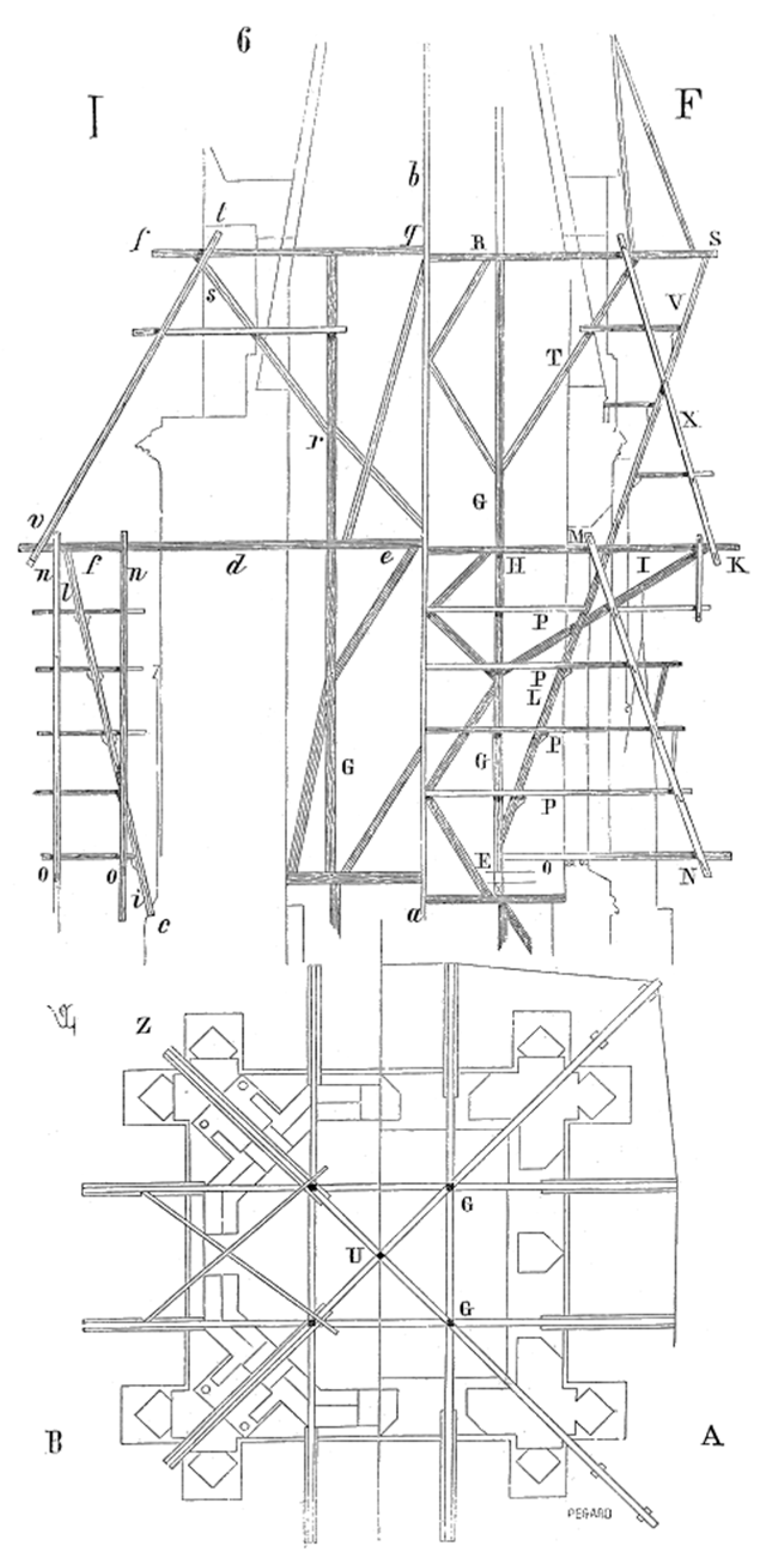
Since no technical drawings of scaffolding have survived from medieval times, the technical drawings from the 19th century related to Gothic towers are particularly valuable. In this chapter, two of these will be discussed. One of them was built for the 1838–1842 reconstruction of the spire of the south tower of Stephanskirche in Vienna, the other one is listed by Viollet-le-Duc in his dictionary.
Dismantling and reconstruction of the Stephanskirche’s spire top in the 19th century.
The top of the spire of the south tower of the Stephanskirche was dismantled and rebuilt between 1838 and 1842 [
76] (p. 312), [
77] (p. 106). First, scaffolding was built around the top of the spire; then, after onsite condition surveys, a decision was made to dismantle and then re-build the top. The architects were Josef Baumgartner and Paul Sprenger. Sprenger made the top of the spire out of metal as a great innovation (this later proved to be a bad decision, and the spire was once again made of stone during the reconstruction between 1860 and 1864).
This construction was especially well documented: a painting [
77] (p. 106), a daguerreotype [
77] (p. 107), and a technical publication were made about it [
50]. The latter introduces the scaffolding both with a textual description and in drawings (
Figure 17). The scaffolding was made by carpenters Jakob Fellner and Anton Rueff. The description of the scaffolding can be found on pages 8 and 9 in the article of the Allgemeine Bauzeitung; it will be very briefly summarised below.
The material of the scaffolding was larch, and it had 21 levels. Its lower level lay on top of the stone gallery running along the bottom of the spire; the other levels were on top of each other. The horizontal rods led through the openings of the spire, so they did not add a load to the stone spire. Their ends were fastened together using carpentry joints reinforced with metal inside the spire, and here, a vertical rod system was also added to them, serving as a superimposed load on the parts with the cantilevers. The system changed at the 11th level (marked with a “k”) because, from this point on upward, the spire was not suitable to have horizontal rods protruding into it. The upper levels stood on top of each other, completely independent from the spire, not even touching it. The (level-high) posts were stiffened by saltires at each main level, so this part of the scaffolding was a structure that was stiff on its own. The uppermost level served to put the eagle decorating the top into place. The eagle had to be lifted to an additional 2.5 m high in order to be able to insert the vertical iron rod located at the bottom of it in place. In order to do this, a pulley was installed on the uppermost cross-beam. Railings were present at each level of the scaffolding, and the individual levels could be accessed using ladders. The published drawings were created by Jakob Fellner based on the completed scaffolding because it was not possible to make detailed designs beforehand. The scaffolding was built using a series of decisions made on the site, always adjusting to the situation at hand for each level.
The lifting of materials was also directed by the carpenters. For this, an almost fully vertical wooden track was created on the outer side of the scaffolding, between levels “t” and “e”. The published drawing only contains the line of this track but not its details. The rope used for lifting ran through a pulley that was installed at the uppermost levels of the scaffolding; the structure was driven by a simple iron crank handle. Building materials were lifted first inside the tower, from the floor of the church through the openings in the vaults to the level beneath the clock (level “E”). From here, lifting was vertical and was carried out on the outside, all the way to the bottom of the wooden track.
There were four phases in lifting the building materials from the ground all the way to the top of the tower (so four lifting devices had to be used at the same time): first to the level of the clock; next, on the outside, vertically, to the spire gallery; then obliquely, along the lines of the spire, to the uppermost level; and here, a separate pulley served to lift the top into place.
The summary of Trost’s description ends here. The load-lifting method of medieval times must have been very similar to the one he describes, not counting the wooden track (no such thing is shown in any contemporary representations). Zykan writes the following about the machinery used in the construction of the Viennese south tower, based on contemporary sources [
79] (pp. 77–78, footnote 27): accounts often mention a lift (Zug) that was driven by a treadwheel and ran inside the tower. One of these was still in operation in the 16th century, so the open stone ring of the vaults was left uncovered. According to a source, in 1562, a Türmerknabe (“tower boy”) fell into the church from the treadwheel, down 30 Klafter (56.88 m). Here, the original location of the treadwheel is discussed as being above the bell tower. In 1426, after the octagon level had been completed, another lift was added in order to move the material to great heights in a number of phases. In 1429, both the old and the new lifts were mentioned.
There is only one representation in the catalogue of Binding that shows an external scaffold similar to the one described by Trost [
63] (p. 204, catalogue item 620). This originated in France in 1447/50.
27 The representation shows the construction of a church tower. The scaffolding starts at the height of the main cornice of the church and extends all the way to the top of the tower. Around the square-shaped area of the tower, two series of posts support the work levels. Stiffening is provided by saltires and angle braces, but not all of them are shown on the drawing. The outer series of posts ends at the bottom of the octagon, but the inner series of posts next to the wall stretches further and forms the outer support of the work levels running around the octagon. The cross-beams are probably supported by the walls here.
At about halfway up the octagon, the rectangular scaffolding turns into an octagonal shape. The posts are simply standing on the cross-beams of the uppermost square-shaped level. Ladders are only shown in the lower levels, but they were definitely used in the upper levels as well. All work levels have railings. The scaffolding ends with the cantilever crane at the very top, and there are two workers putting the metal cross on the top of the spire in place. This cantilever crane was probably rotating, so it was suitable for horizontally positioning the load. The lightness of the entire structure, together with the fact that there is only one pulley on the crane, suggests that it was not suitable to lift greater loads. It is important to take into account that the spire on the drawing is not very large: Richard A. Jones estimated that it is about 4.5 m tall, with approx. 1 m greatest inner diameter, so it would not have been possible to build it from the inside [
80] (p. 15).
Viollet-le-Duc’s Tower Scaffolding
In the entry “échafaud” in his dictionary, Viollet-le-Duc discusses the matter of scaffolding in the case of Gothic towers at considerable length [
48] (pp. 103–114). According to the entry, the observation of scaffold holes suggests that, above a certain height, suspended scaffolds were used. The walls of towers usually thin out with height, which means that the wall face actually moves further to the back. These locations are excellent for supporting the scaffolding, inside or outside. It is not very difficult to suspend a scaffold on the outside of an existing building, but building up a new structure this way needed some ingenuity, which was a common characteristic of medieval master builders. Viollet-le-Duc observed that the towers were constructed using suspended scaffolds, leaving the lower parts of the facade free. It is important to note that a suspended scaffold is not the same as the cantilevered scaffolds discussed above. In the latter case, every level is supported by cantilevers walled into the masonry, while in the first case, they are not. Although the scaffold hung from the building, it was more or less independent of the masonry.
Detailed drawings and descriptions of such scaffolding were published by him, which he reconstructed based on the scaffold holes in existing buildings (
Figure 18). The core structure of this was a rigid, triangular framework, completed before the walls of the bell storey were built. The work levels were then installed on top of this core system. The system could be built level by level, in phases, and when the walls were finished, the entire scaffolding could be removed from the inside.
Viollet-le-Duc also presents another type of scaffolding that is a combination of cantilever scaffolds and scaffolding with posts (
Figure 19). The scaffolding starts from a cantilever, and its horizontal rod runs through the entire width of the wall. Posts start from here, and the cross-beams of the next level are built into the wall on one side, and on the other, they are supported by the posts. If an existing building had one series of thick scaffold holes and more than one series of thin ones, this kind of scaffolding was used. This solution was especially useful in the case of tall Gothic buildings and church towers, where it was not possible to start the scaffolding from the ground [
48] (p. 108).
Preserved Scaffoldings
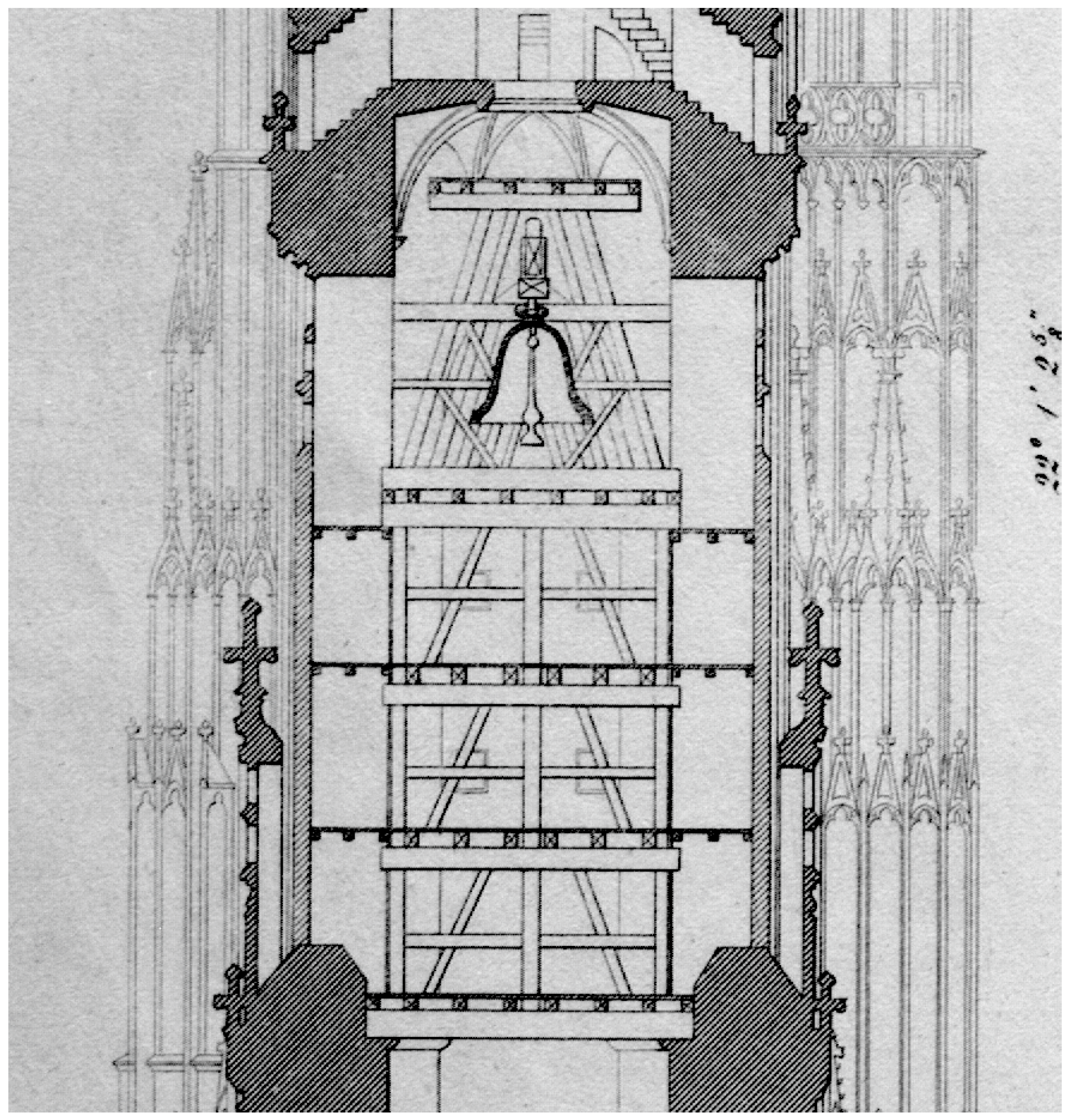
The scaffoldings mentioned in this chapter are either preserved inside towers or can be reconstructed from traces. Some of them had/have a primary function as formwork or bell stands, and it can be supposed that they were also used as building scaffolding. This theory in general is supported, among other things, by the efforts of the Gothic construction industry to work economically (material saving). It seems logical that, if a major timber structure was built to support the bells or to define the shape of the spire, they would also use this timber structure as building scaffolding.
The bell stands of the Gothic period are especially suitable for construction scaffolding since, in the case of larger towers, these structures were internal timber towers themselves. The reason behind this is that, from the point of view of statics, it is better to have the load of the bell tower stressing the tower itself at a lower point since the horizontal loads originating from the movements of the bell will have a smaller level arm on the tower as a vertical cantilever. This was already discovered in the time of the Gothic era (of course without the theoretical background), which is why tall bell stands inside masonry towers were built: the loads are transferred to the walls at a relatively low position, decreasing the level arm, but the bells can still be located high [
81] (p. 94).
In his comprehensive article on medieval and early modern era bell stands, Heinrich Biebel mentions a number of churches where the bell stands were used as construction scaffolding: the Minster in Freiburg am Breisgau, the parish church in Deutsch Eylau (today Iława, Poland), St. Ulrichskirche in Augsburg, and St. Martinikirche in Braunschweig [
81] (pp. 94–98). He also mentions, in general, that the type of bell stands where the actual bell stand is supported by a so-called lower scaffold
(Untergerüst) may have also been used as construction scaffolding.
There are a number of representations in the catalogue of Binding where the scaffold is shown inside on the upper levels of a tower, in a number of cases combined with a treadwheel [
63] (catalogue items 94, 468, 537, 618).
Freiburg, Glockenstuhl
In the tower in Freiburg, the bell stand starts on the square-shaped area of the tower, and its upper part protrudes into the octagon (
Figure 20). Its structure is a truncated pyramid, standing on the narrow cornice on the inner side of the wall. Underneath it there is a vault with an opening in the middle; the bell stand does not impose any load here. In addition to the posts forming the edges of the truncated pyramid, a further eight posts are installed along the entire height, so ten posts support the structure; their profile is about 50 × 50 cm [
82] (p. 505), [
83] (p. 64). The bell tower itself is about 11 m wide and 17 m tall [
81] (p. 95) and has four main levels. There is a treadwheel on the second level; it was not the original one already in the 19th century, but certainly there was one present in medieval times as well [
82] (p. 505). The bell stand was made mainly of pine, and only a few of its parts were made of oak; the trees used were cut in 1290/91 [
83] (p. 64).
The structure is especially interesting because it is older than the walls around it [
82] (p. 505), [
76] (p. 64); therefore, it must have helped the construction. It was probably used for lifting up materials inside, storing materials, and serving as a work scaffold [
82] (p. 505), [
84] (p. 193), quoted by [
85] (p. 136). The presence of the treadwheel supports this statement too. Inside the famous openwork spire, in addition to the treadwheel, there must have been a work platform including a crane, as the small, currently unused stone corbels indicate [
86] (p. 113). Accordingly, the circular opening that used to serve for load transport can be found in the vault of the bell storey [
19] (p. 19).
Besides the bell stands mentioned earlier, which probably served as construction scaffolding as well, the former bell stand of the south tower of the Stephanskirche should also be mentioned (
Figure 21). Based on contemporary account books, it can be deduced that the bell stand was built earlier than the walls around it [
79] (p. 45). The bell stand in Vienna belonged to type “B” of the Biebel categorisation:
‘Glockenstuhl mit Untergerüst’, bell stand with a supporting lower scaffold. Biebel is of the opinion that it was made in the early modern times [
81] (p. 101), but even if it was so, its predecessor from the medieval times must have been similar, since it does not differ basically in its design from the medieval examples presented by Biebel. Its lower stand is a square-based rectangle with multiple stiffening and four levels. It is interesting to note that the drawing published in Trost’s article [
50] (Taf. XDII) shows beams and planks next to the wall already on the level where the bell tower itself starts, not only on the lower stand. The beams and planks on the top of the bell stand are also noteworthy; these must have formed a suitable work platform for the building of the vault. Unfortunately, this bell stand has not been preserved.
Both in the cases of Vienna and Freiburg, there is a hole in the vaulting above the bell stand. It can be observed in the Freiburg drawings that the two middle beams are moved apart on each level, which made it possible to pull the loads up in between them. The two middle beams are relatively close to each other on the Viennese drawing, which means these must have been put into place only at the end of the construction, similar to the middle planks. A source from the 16th century reports that there was a treadwheel above the bell stand [
79] (pp. 77–78, footnote 27), and during the reconstruction in the 19th century, loads were lifted inside the tower as well [
50] (p. 9). This proves that this task was possible to carry out even without dismantling the bell stand.
The Scaffolding in the Salisbury Spire
The timber structure preserved in the stone spire of the crossing tower of Salisbury Cathedral (England) is the only existing one of its kind (
Figure 22). It was used as construction scaffolding during the construction of the stone spire around 1300 [
80]. This structure was thoroughly researched by Tim Tatton-Brown; in the following paragraph, his findings from his relevant articles [
87,
88] are briefly summarised.
The construction of the scaffolding was as follows. First, cross-beams were laid down in the centre lines of the tower walls. Where the beams meet, a central mast is erected, and four other posts start from the quarter points of the beams. The scaffolding was built level by level, together with the stone structure. The beams were braced to the posts; therefore, the entire structure is stiff and rigid. Parts of the octagonal work platform are preserved on the second and third levels. The system of the structure changes from the fourth level on: the four side posts do not extend further, and the levels from here are only supported by the middle mast using inclined angle braces. Going up from level nine (the inner width of the stone structure is only 1.5 m here), a temporary outer scaffolding was also needed. The scaffold holes are still present (equipped with removable plugs with metal handles), and they are used even today when the top needs to be repaired. There is an iron structure constructed between the top of the middle mast and the cap-stone, which was built at the same time as the tower. This consists of three vertical rod sections; where the sections meet, crosswise metal rods link the stone structure of the spire. There is no consensus in the literature about the function of this metal structure [
89] (pp. 287–290).
Smaller Scaffolds in Spires in Central Europe
Although no scaffolding similar to the one at Salisbury is preserved, it is still possible to find timber structures inside smaller stone spires that may have served as construction scaffolding. Since these are hidden ancillary structures located in the heights, it is very difficult to become aware of them. Philip S. Caston introduces the one-time scaffolding of the St. Matthäus Church of Murau (Austria) in detail, reconstructing the entire process of construction in his excellent book, which discusses medieval crossing towers in German-speaking territories [
26] (pp. 17–27). The tower itself is a simple, solid stone structure with a spire and was built at the beginning of the 14th century [
26] (p. 18). The traces of a dismantled timber scaffolding can be found inside the spire. The spire was built on this scaffolding, serving as a centre scaffold [
26] (p. 21).
28 This structure did not function as construction scaffolding, and its primary task was to define the edges. The construction scaffolding was a separate construction, as indicated by the surviving scaffold holes.
Based on the traces, Caston reconstructed the process of the construction of the spire and the scaffolding in detail. The scaffolding was built level by level, parallel to the building of the spire. The work levels were about 2 m from each other. It is not clear how the last stones were put in place, but it seems to be sure that it was not performed from the inside [
26] (p. 25).
The remains of a scaffolding can be found in the southwest spire of the Stephankirche in Vienna.
29 The rods running along the edges were fastened together on their outer side using horizontal planks, until a height of about 1.5 m. This plank covering served as the formwork for the brick spire. Above this height, the brick rows were built without planks [
90] (pp. 132–133).
A medieval timber structure survived in the north tower of St. Martin’s Church of Zipser Kapitel (Szepeshely) in the Kingdom of Hungary (now Spišská Kapitula, Slovakia). It can be dated to 1382/1383 using dendrochronological evidence [
92] (p. 34). Similar to Murau, the rods run along the edges, and further rods are present at the middle of the edges; these reach the beam cornice running around the middle. In order to decide whether this scaffolding was used as construction scaffolding, a very thorough on-site examination would be needed.
Unfortunately, there are no photographs preserved about the dismantling of the spire of the medieval Franciscan church in Bratislava, Slovakia
30, even though a source from 1865 informs that inside the tower “even today there is the entire timber structure on which the stone spire was raised” [
94] (p. 287). The statement from the same article that “the bell stand reaches the wall of the tower all around” is also interesting since the bell stands usually do not touch the wall due to their function, discussed above. Therefore, it is possible that this structure was primarily an internal scaffolding.
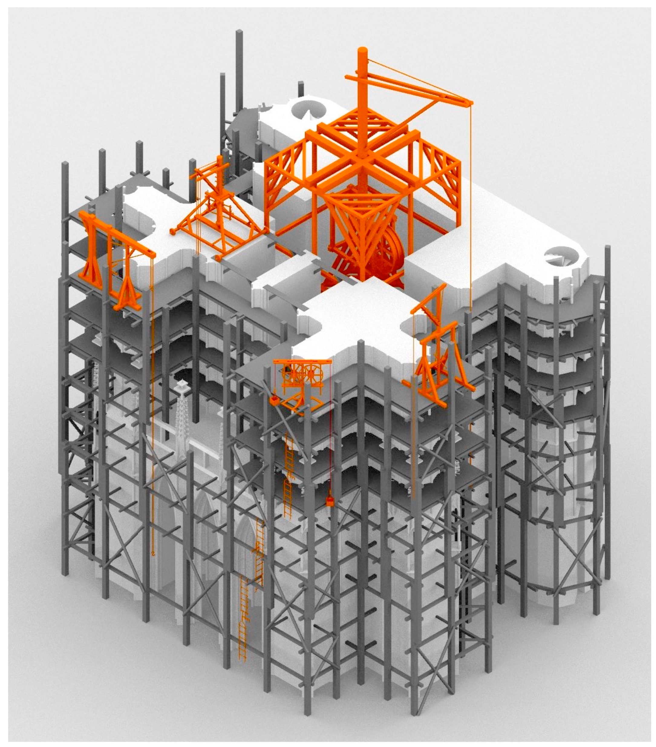
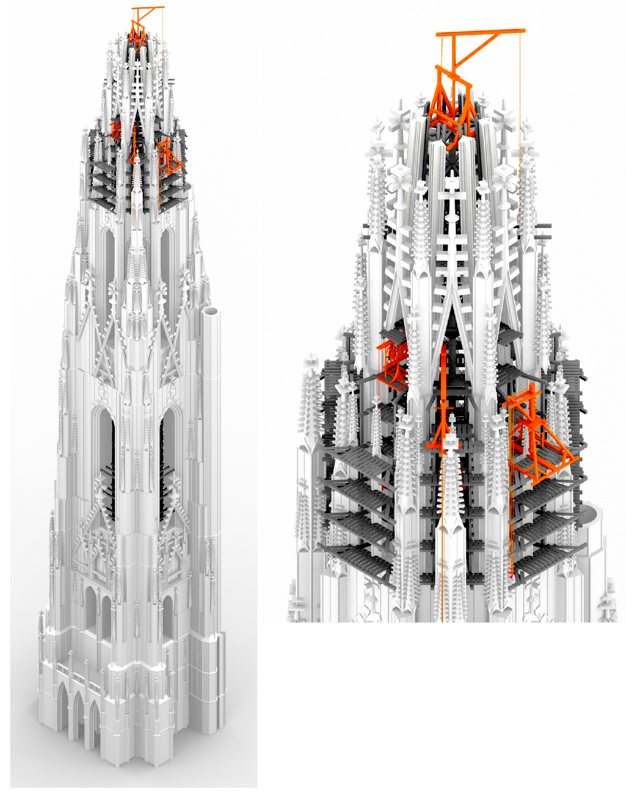
3. Results: The Phases of a Tower Construction
In the following, the phases of a tower construction will be presented with the example of the Viennese north tower, using hypothetical illustrations with the application of the possible devices used (scaffoldings, machinery), as described above. Every element of these models is based on the knowledge discussed above.
As mentioned earlier, the most complete floor plan of the north tower is No. 105.064
31, and the most complete elevation drawing is 105.067
32, so these were used for the model. Where these two deviated from each other, the floor plan was followed. Since the goal was to reconstruct a structure based solely on the original plans, only these drawings were used for the model, and the photographs taken of the actual tower were only taken into consideration in order to interpret the drawings correctly. Therefore, for those parts not shown in the drawings and in cases where it is impossible to deduce how they should look (mostly the east and west facades of the ground floor), they are represented only schematically.
The scaffolding types introduced in the previous chapter were applied to these models as follows:
Lower part: scaffolding with posts, on the outside.
Bell storey: bell stand as stay-in-place scaffolding, smaller auxiliary scaffolds.
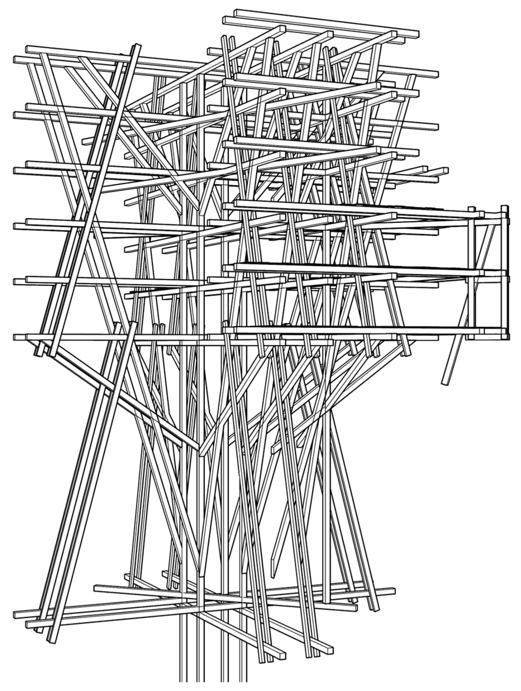
Octagon level: inner scaffolding, with extensions for the construction of the giant pinnacles.
Spire: centre scaffolds as inner work scaffold, an auxiliary scaffolding for the pinnacles, positioned on the gallery around the spire, and on the top, an external scaffolding.
33
For every stage, the most logical and economical solution was chosen, but it has to be emphasised again that this is just one of the possibilities, although a probable one.
The reason for choosing the outside scaffold with posts for the lower level is that the inner scaffold provides no advantages over the outer one. Additionally, the use of an outer scaffold on posts is common on lower levels in works of art depicting tower construction. Another consideration was whether the cross-beams should rest on the wall or on an internal row of columns. The decision was made in favour of the former option, as it is the more commonly depicted solution in the contemporary representation discussed above.
In the case of the upper levels, using inner scaffolding standing on the wall entablature seems more practical when compared to using outside scaffolding, especially since it can be used later on as a bell stand. In the case of the spire, a combination of centre scaffolds and work scaffolds was chosen, even though neither in Freiburg nor in Salisbury was a centre scaffold needed. These two spires differ greatly from the spire in Vienna since both of them basically consist of a series of trapezoid elements, which are stable on their own even in a single row, so it is not necessary to have a centre scaffold. The main structure of the spire in the case of Vienna is the ribs forming the edges; these needed to be supported during the construction. Also, centre scaffolds were used in the case of smaller spires as well, which is another reason for their application in the model.
In Binding’s catalogue, there are representations in the very same codex that show the construction of lower levels using external scaffolding and the construction of upper levels using inside ones [
63] (p. 190).
It is very difficult to identify scaffold holes on the realised parts of the Viennese north tower. According to Kieslinger, there are not too many of them in the entire church except for the south tower, but those probably originate from later repairing works [
91] (p. 149).
There are three very valuable pieces of data at our disposal regarding the construction of the north tower: two very similar crane plans from the archives of the Viennese workshop from about the year 1500 [
31] (p. 412), [
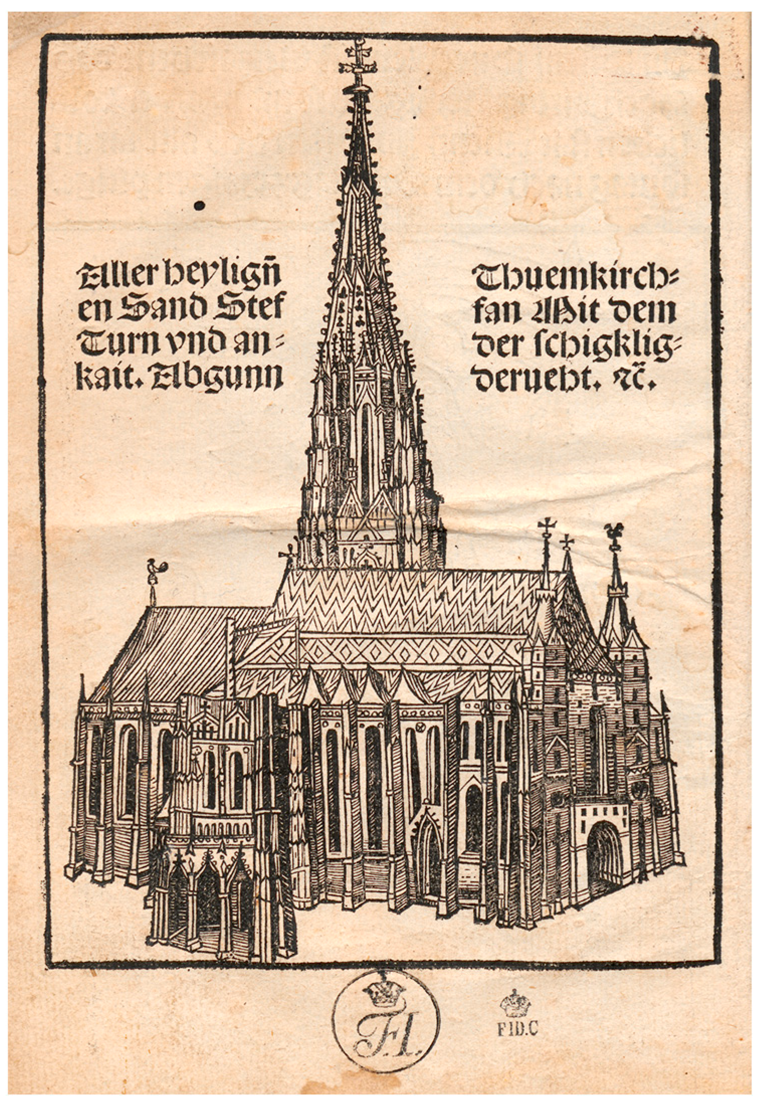
77] (p. 82), and a woodcut from 1502 showing the church from the so-called Wiener Heiltumsbuch (
Figure 23). The tower was still under construction at this time. These drawings show a huge crane equipped with a treadwheel in a timber frame. The crane on the woodcut might very well be one of the cranes in the crane plans, or more precisely, the cantilever crane, despite the schematic representation. An interesting addition to the construction is the so-called
Asylring at the bottom of the tower, which is still preserved today (
Figure 24). Kieslinger is of the opinion that this belonged to the crane shown on the woodcut and served as a rope guide [
91] (p. 148). This only makes sense if the crane is in the heights but the drive is on the ground; the crane shown on the plan, however, has the drive in the heights as well.
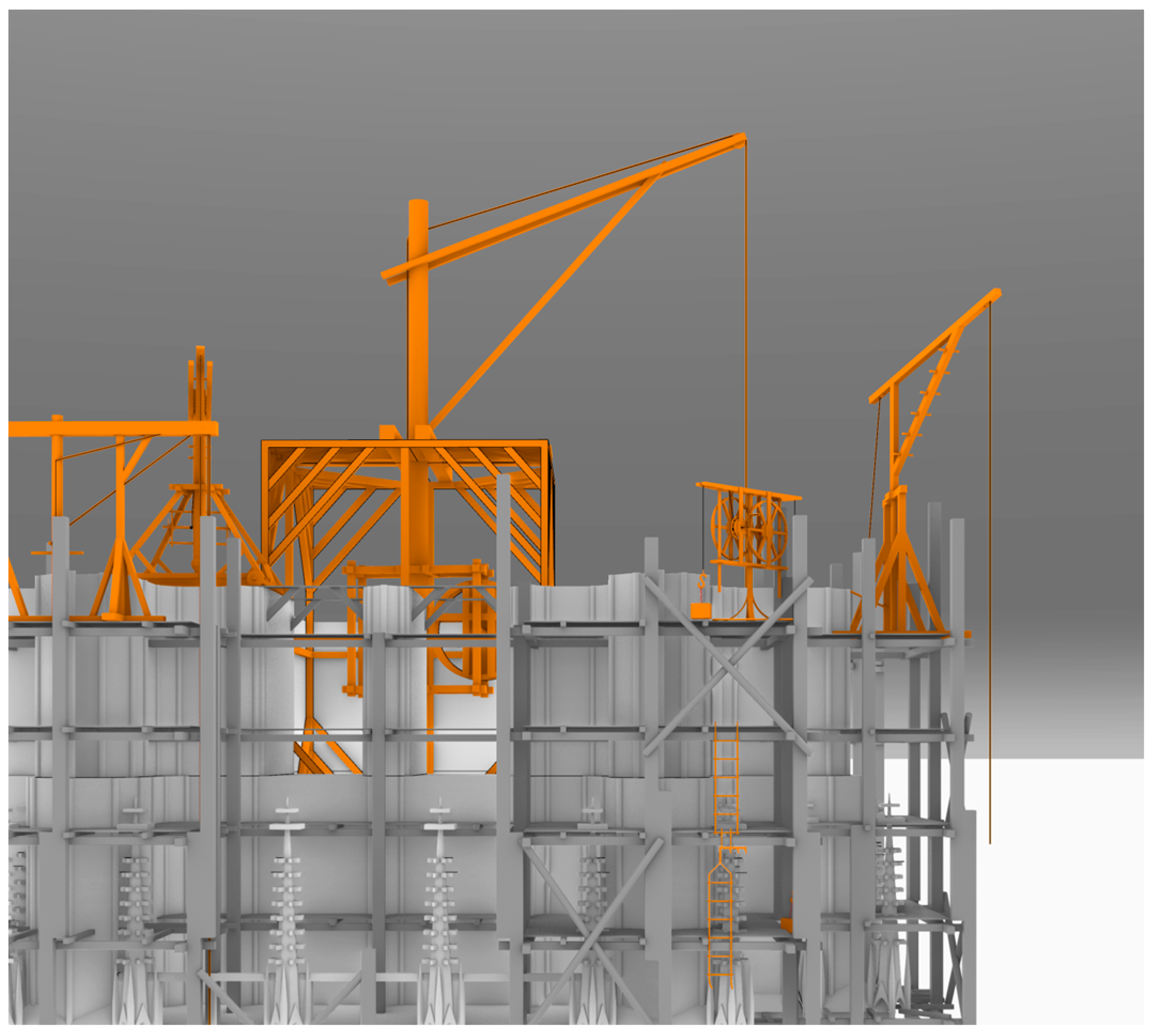
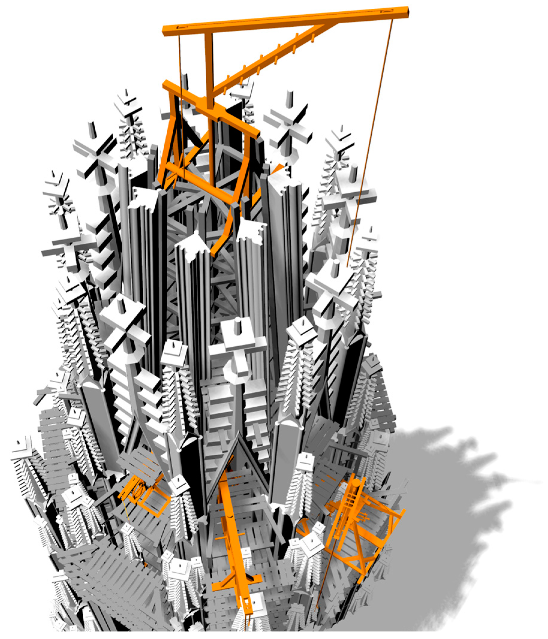
3.1. First Phase: Tower Body
Drawings used as sources:
The main aim was to introduce the application of Hans Hammer’s machines, but the crane drawing from Vienna could not be left out. This drawing is special in the sense that, as opposed to Hans Hammer’s machine drawings, it was prepared according to the convention of architectural drawings.
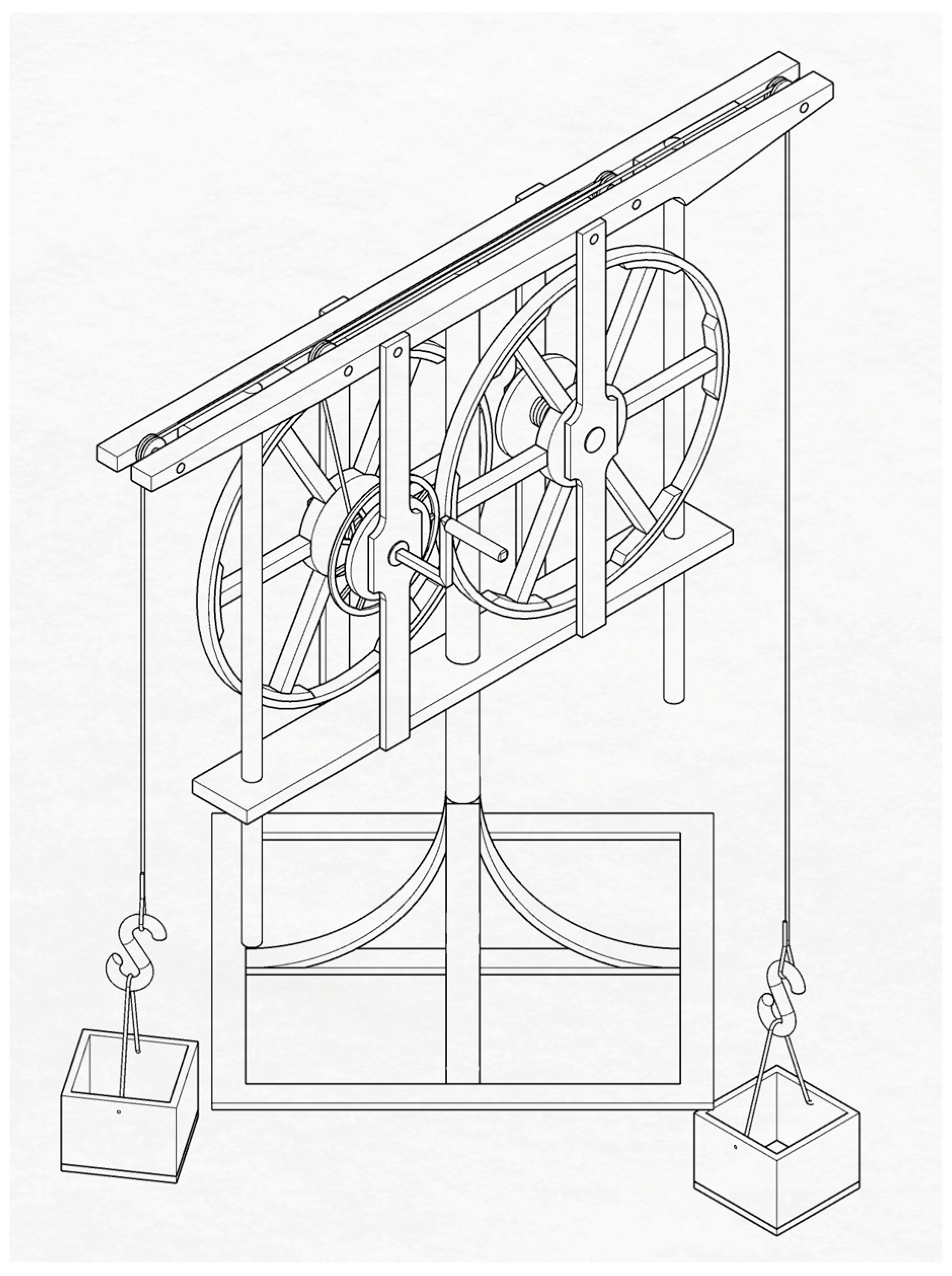
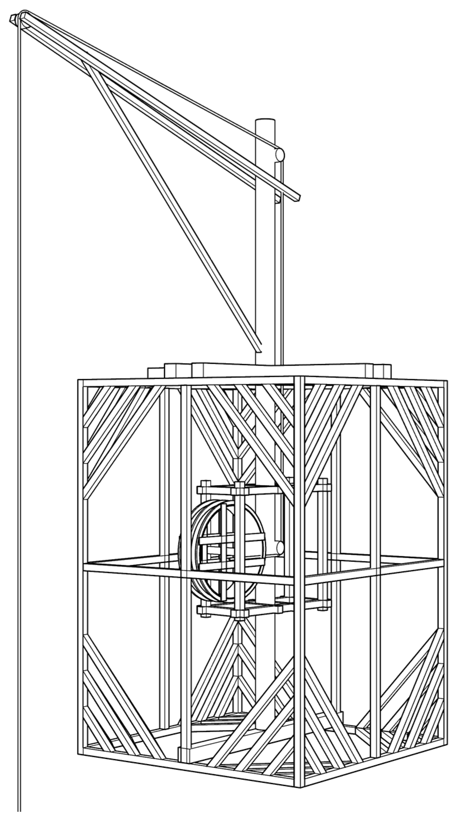
34 The crane in the design shown on the plan would not be stable, so the model was supplemented with bracings (
Figure 25), similar to those of the medieval crane of the Cologne cathedral, preserved until the 19th century (
Figure 26). It is certain that treadwheel cranes built in rectangular frames, similar to the one in Vienna, existed in medieval times because they can be seen in many representations.
35 In the case of the drawing from Vienna, the treadwheel is encased in a separate wooden frame. This frame probably rotated together with the crane post (
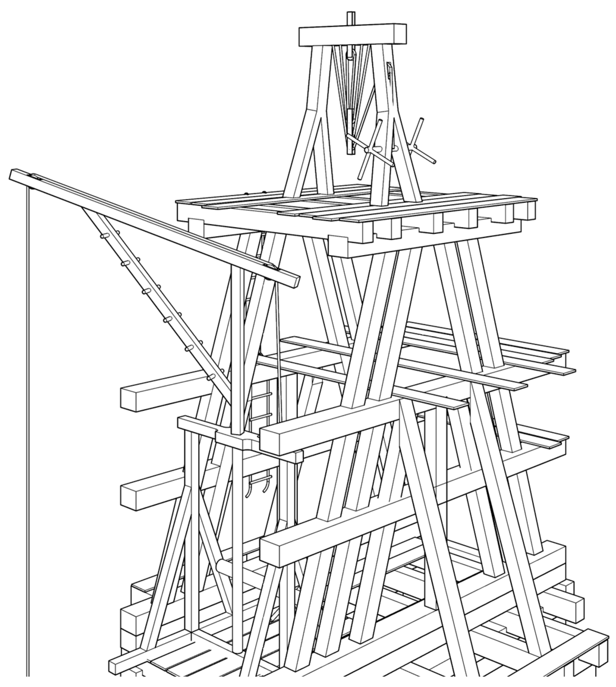
Figure 13).
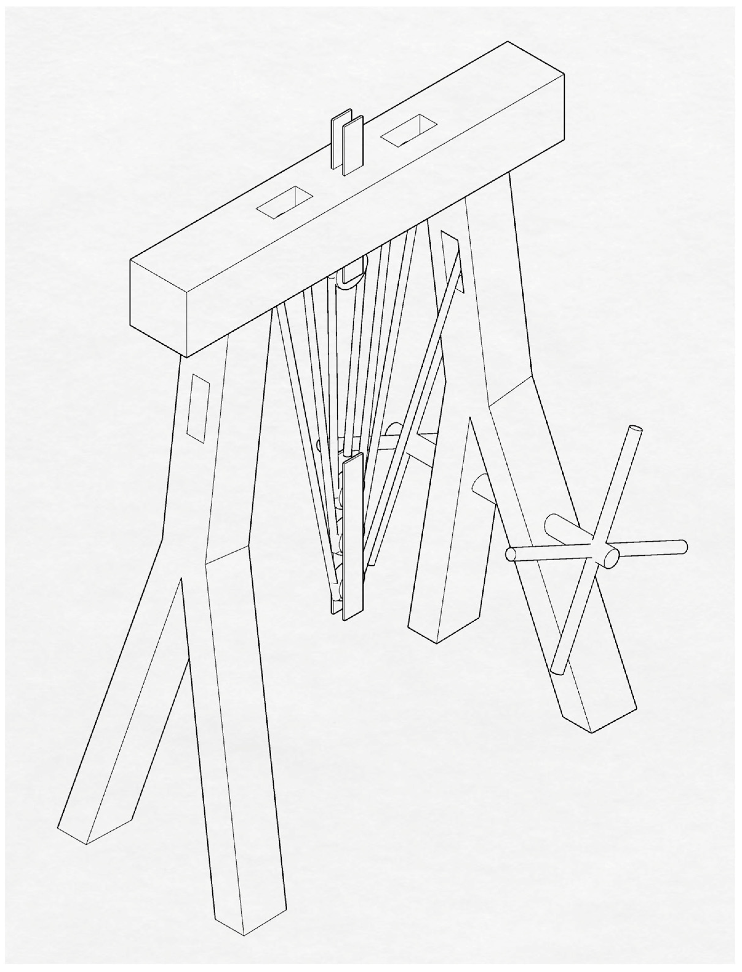
As evidenced by a number of drawings in the Binding catalogue and the crane from Cologne, it seems that such a large crane positioned in the middle of the tower was used regularly for tower construction. The construction procedure probably went thus: first, this approximately 20 m high “tower crane” was erected, then the construction of the scaffolding started around it, and in parallel with building the scaffolding, the tower was built. Once the walls reached a height where it was no longer possible to use the crane, it was relocated to the wall top together with its rectangular frame, and the new phase of construction began. Therefore, the height of the crane actually determines the height of each construction phase. It seems logical that the scaffolding was moved together with the crane, so only as many levels of scaffolding were completed as covered the entire height of the crane. Many medieval representations displaying scaffolding with posts (for example, the two referenced above) show that the lower work levels are no longer there, only the posts and the stiffeners. The posts were probably extended with additions until a certain height, but due to material economy, those work levels that were no longer needed were disassembled and rebuilt at higher levels.
In the 3D visualisation, the construction is at the level of the springing level of the double windows (
Figure 27). Around the tower stub, a scaffolding with posts can be found, stiffened with saltires around (
Figure 28). Longitudinal rods are fastened to the posts, and the cross-beams are supported by these and the walls. The lower work levels and part of the cross-beams have already been disassembled. In the middle, the tower crane is positioned similarly to the one shown in the woodcut. One of Hans Hammer’s wheeled cranes is moving on the wall top (4r 1); thanks to the great wall thickness, it can be positioned and operated there. Hans Hammer’s 3r 1 machine is placed in the north-west corner of the scaffolding (
Figure 29). Large-scale towers have great wall thickness on the lower level, and this gradually decreases towards the top. In the case of the Viennese towers, it is known that the walls are layered on the lower level: the inner and outer shells are made of ashlars, and inbetween they are filled with rubble stone [
79] (p. 33). The inner shell is almost completely featureless, but the outer shell is richly articulated. In my drawing, the large tower crane in the middle primarily lifts the inner featureless ashlars; the smaller building stones of the façade with detailed carving are mainly lifted by smaller cranes; therefore, the work can be carried out on many fronts simultaneously.
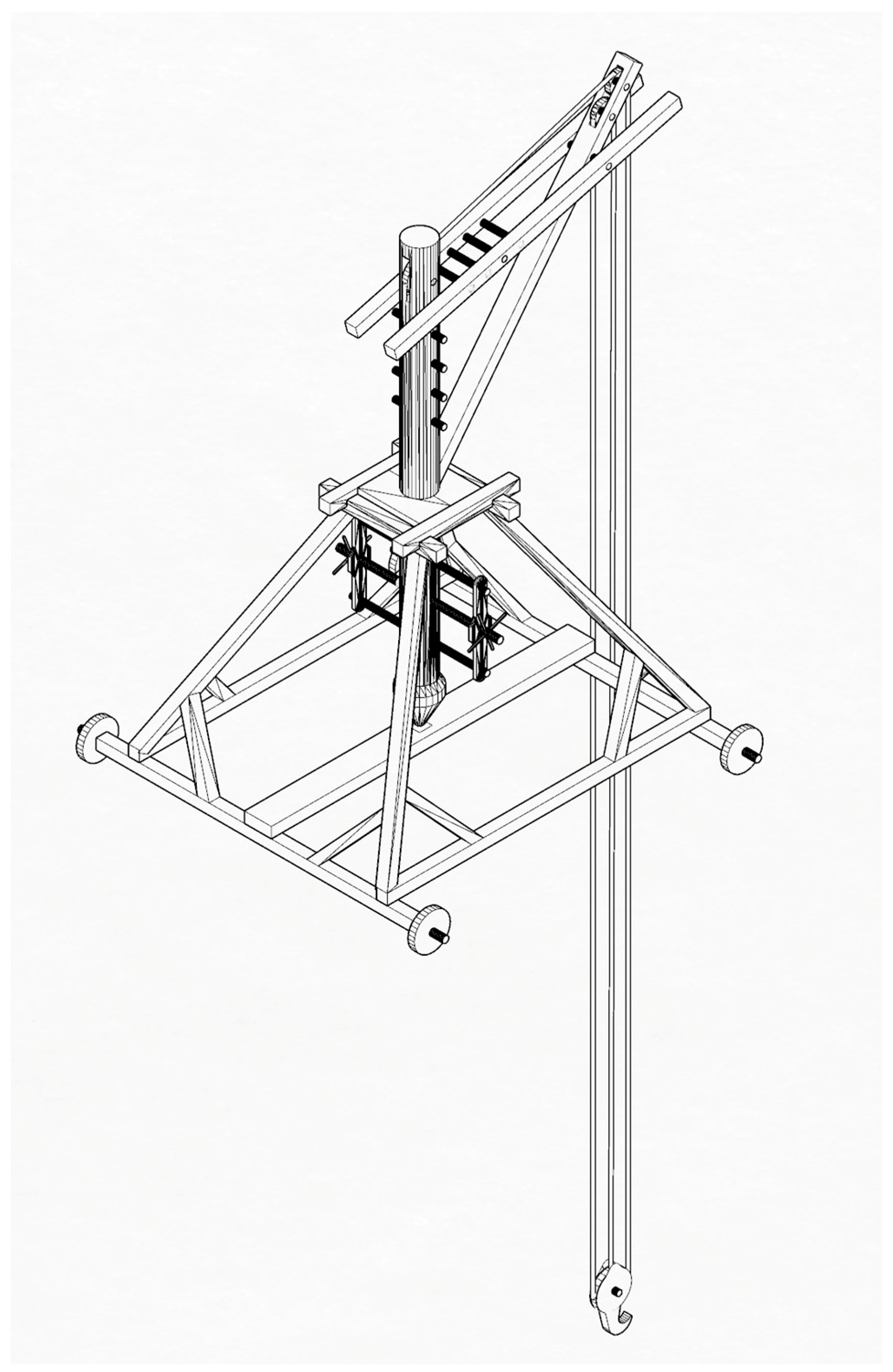
3.2. Second Phase: Freestanding Square-Shaped Part
Drawings used as sources:
The visualisation shows the construction of the freestanding square-shaped part (
Figure 30). The model shows the solution used in Freiburg: the bell stand is completed prior to the construction of the surrounding walls, and it functions as a construction scaffolding as well (
Figure 31). Sources indicate that, in the case of the south tower in Vienna, the situation might have been similar [
79] (p. 45).
On the model, at the top of this bell stand scaffolding, one of Hans Hammer’s frame cranes is positioned (4v 1), which is suitable for lifting heavy loads (
Figure 32). It was mentioned in the overview of scaffoldings that scaffoldings of the medieval times were probably unsuitable for storing heavy stone building material. Bell-stand scaffoldings are exceptions. They were designed to bear the load of bells of many tonnes, so they are perfectly suitable for temporarily storing stones. This made it possible to work on the stones at a height: the frame crane lifts the large stones to the proper height, where the stones are deposited, cut, and hewn, and then they are put in their place using cantilever cranes, which are suitable for horizontal positioning of the loads.
It is probable that, in addition to using large scaffoldings, multilevel scaffoldings were also used supported on cantilevers, which are shown in the drawing published by Viollet-le-Duc (
Figure 19) [
48] (p. 108). In the case of the tower in Vienna, this structure would have been ideal to build the interlocking gables. At the bottom of the gables, the wall of the tower moves back, which creates a suitable platform for placing the cantilevers of the scaffolding. The parapet of the large window also offers a suitable surface. In the model, such auxiliary scaffoldings are displayed on each of the two sides of the tower (
Figure 33).
It is interesting to observe the beams with plank boarding built into the window openings in the drawing published in Trost’s article (
Figure 17). These must have been perfectly suitable for construction; therefore, they are also displayed in the model.
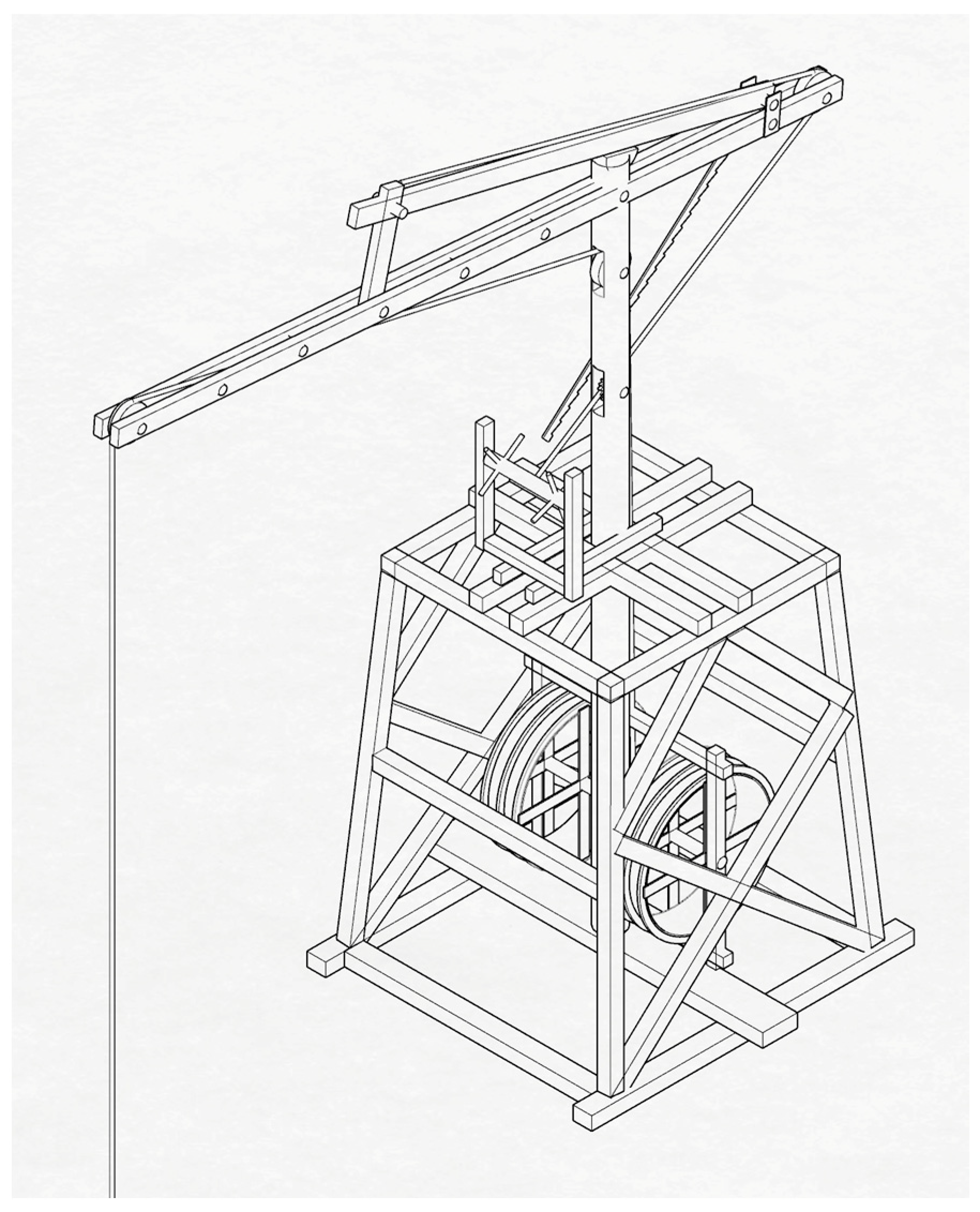
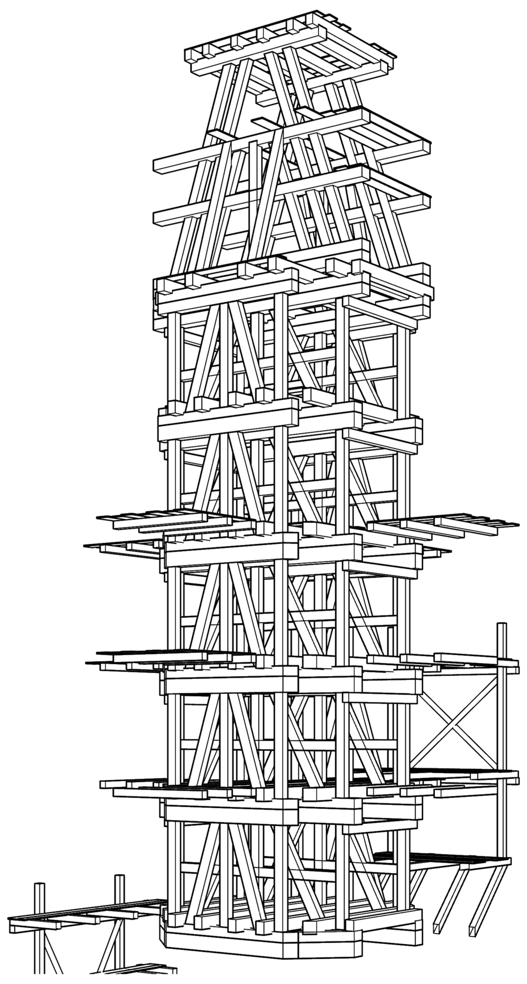
3.3. Third Phase: Freestanding Octagonal Part
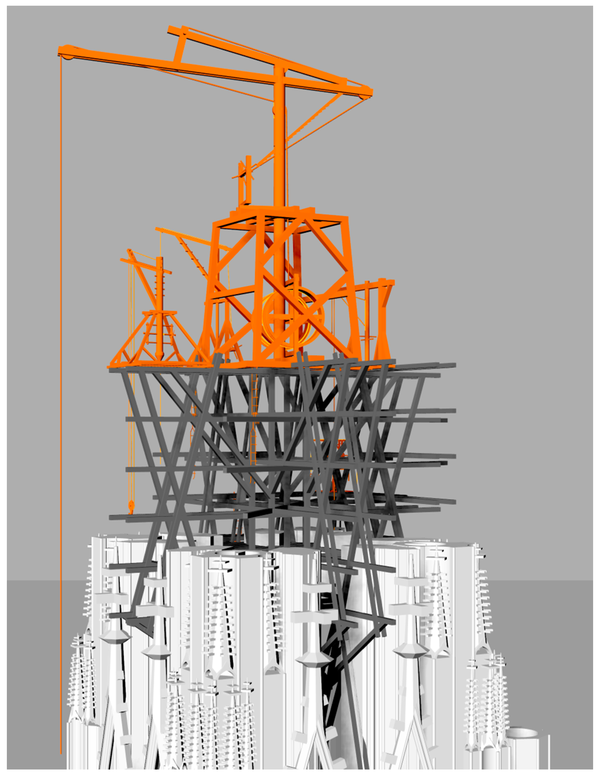
Drawings used as sources:
The figure shows the construction of the tower octagon (
Figure 34). The scaffolding is based on the scaffolding drawing in Viollet-le-Duc’s dictionary (
Figure 18), but it was partly modified since the bell house is square-shaped and there are no large pinnacles. The scaffolding was modified to make it suitable for use in an octagonal bell house and to make it possible to complete the construction of the giant pinnacles (
Figure 35).
In the middle, a large “tower crane” was placed, of similar dimensions as in the first phase; this can be found on page 3r of Hans Hammer’s work (
Figure 10). This is the largest crane in the portfolio and the only one that uses a treadwheel (
Figure 36).
The scaffolding of the previous phase is still in the tower; therefore, the frame crane, suitable for lifting large stones, shown on top of this in the previous phase, can still operate, and this solves the problem of multi-phase lifting (
Figure 37). There are also a few smaller cranes on the model, which were already in use on the lower levels.
3.4. Fourth Phase: Spire
Drawings used as sources:
The construction of the spire is introduced in two steps: first, the construction of the lower part of the spire and the “forest of pinnacles” around it (
Figure 38); then, the construction of the upper part. There is an inner scaffolding inside the spire, similar to the one in Salisbury; it serves as a temporary support for the stones forming the edges of the spire as well. There is an adjoining scaffolding, partly supported by the gallery around the spire, from which it is possible to construct the many pinnacles around the spire (
Figure 39). The scaffolding used in the reconstruction of the spire of the south tower in Vienna between 1838 and 1842 served as a model for this scaffolding (
Figure 17).
Figure 38 shows the construction of the spire to the height to which it was possible to build it from the inside. On the top, one of the smaller, rotating cantilever cranes of Hans Hammer is situated (10r 1), fastened to the scaffolding (
Figure 40).
The spire becomes too narrow above this height to be constructed from the inside. Here, an outside scaffolding was needed, and this is shown by the second series of figures (
Figure 41,
Figure 42 and
Figure 43). In Salisbury, the so-called ”weather door” is located at this height; it is supposed that the switch from internal scaffolding to outside scaffolding took place at this height [
88] (p. 345), [
80] (p. 13). To construct the outside scaffolding shown in the figure, once again the drawing of the scaffolding from the reconstruction in Vienna was used (
Figure 17). The scaffolding is supported by the inner scaffolding reaching all the way up to the spire. The horizontal beams run through the holes of the spire (
Figure 42). To place the finial, Hans Hammer’s 4r 5 machine is ideal: this is a “portal crane”, which has a drive that is independent of the crane itself, so it can be placed on a lower level if needed (
Figure 9, bottom right,
Figure 11). This is similar to the solutions applied in Vienna between 1838 and 1842 and in the 1870s in Cologne. There is scaffolding around the finial, which is stable by itself and has no internal support (
Figure 38 and
Figure 39).
4. Conclusions
The research and the modelling based on it demonstrate that the possible course of a Gothic tower construction can be reconstructed largely based on contemporary drawings and material sources. The modelling has shown that, already in the late medieval times, the technical representations were specialised according to their topic. The architectural drawings had been much like their modern counterparts, so they could be applied rigorously for modelling. The only limitation was the lack of an absolute scale due to the lack of a standardised unit system at that time. Because of this, the actual dimensions of the represented structure were needed to put the drawings to scale. The machine drawings had to be understood before modelling; they cannot be considered as modern blueprints since they lack the orthogonal projection and the exact proportions between their parts, and technical drawings of scaffoldings are entirely missing from the Middle Ages. According to the above, the medieval blueprints of the north tower in Vienna proved to be suitable for the spatial modelling of the structure, with the exception of some contradictions and hidden structures. This model proved to be a suitable ground to “design” the scaffolding for its construction, with the help of medieval representations and the examination of the surviving internal carpentry structures. This way, the modelled scaffolding would be possible to build using medieval technology. The originality and application method of Hans Hammer’s machines and ladders were also revealed with the help of this reconstructed setting, as they were placed in the appropriate places of the 3D models as proof-of-concept. In this way, the series of figures based on models illustrates the possible construction process of a Gothic church tower, including the scaffolds and machines used.
The study of Gothic geometry is an important and relevant topic [
42]. The 3D modelling of contemporary architectural drawings can be complemented with 3D scanning of actual structures; the geometry represented in the drawings can be compared to realised buildings. This way, our knowledge can be deepened about medieval planning and construction processes and methods. The advantages are not only theoretical: this knowledge can be used in the maintenance and preservation of the built heritage.
Due to the nature of the topic, printing as a medium is not fully suitable for communicating all the information contained in 3D models, so an online visualisation was also created, with models and related data that can be viewed interactively [
95]. The website presenting the visualisation is available at the following URL:
https://zbereczki.github.io/gothic-construction/ Accessed on 2 February 2024.


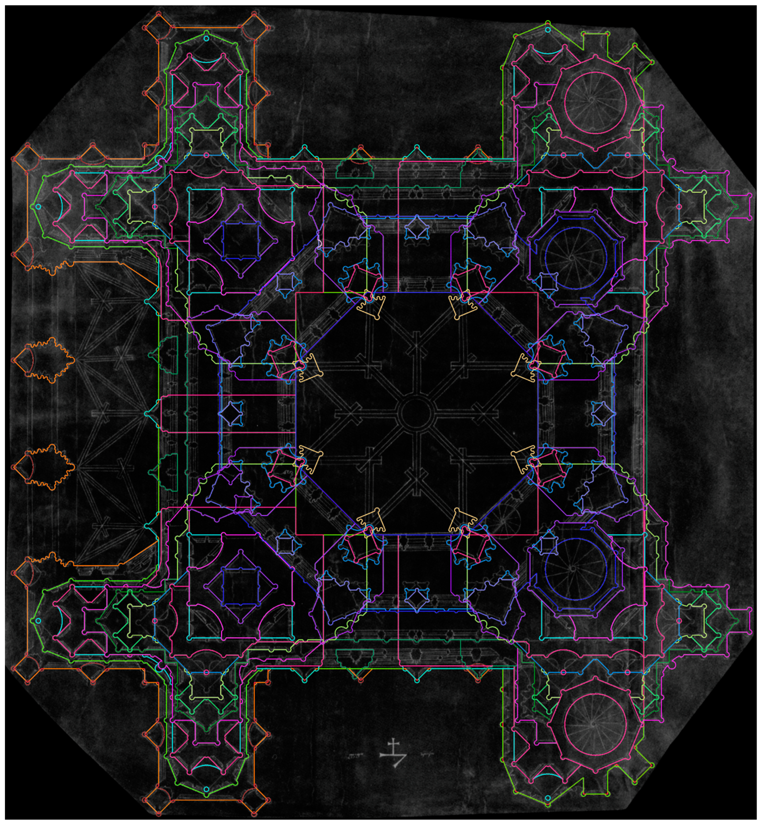
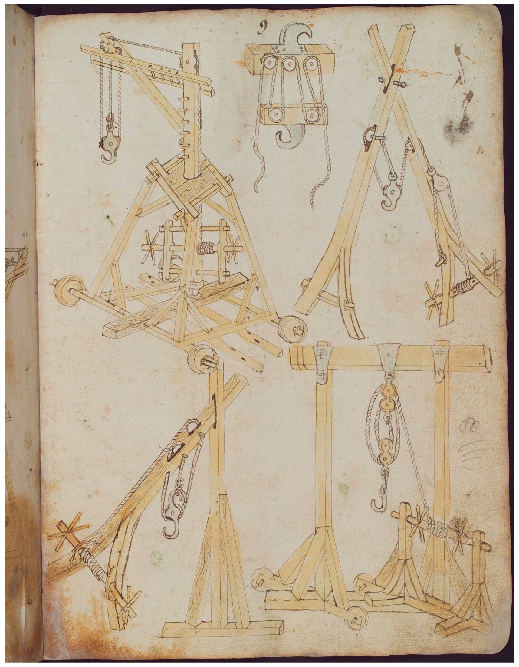
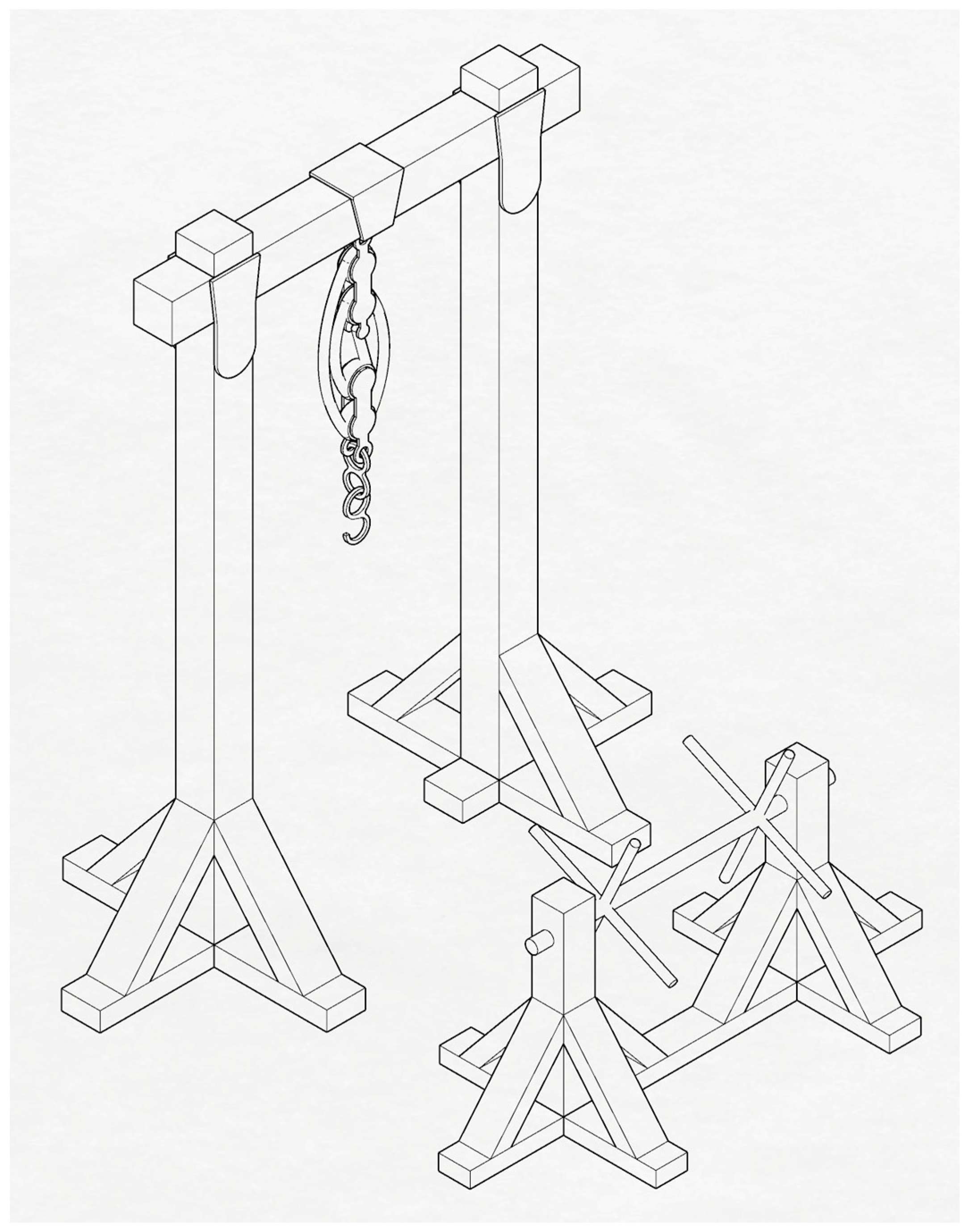
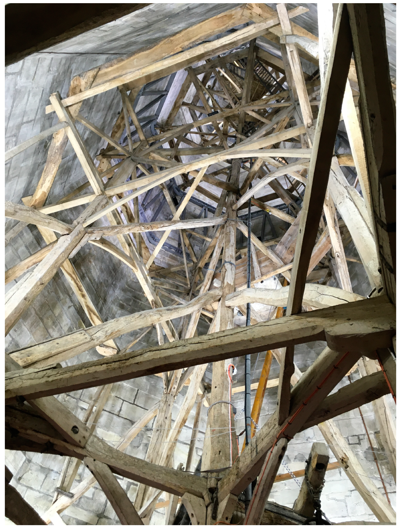
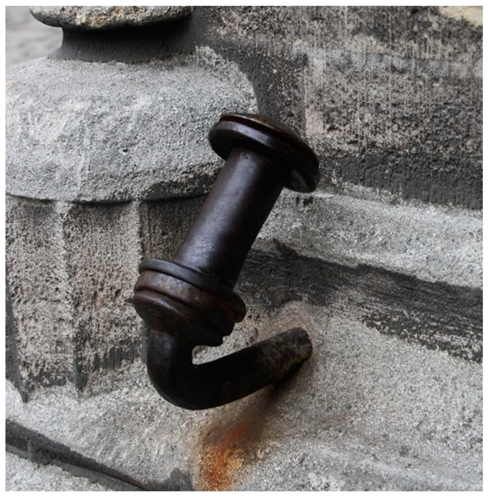
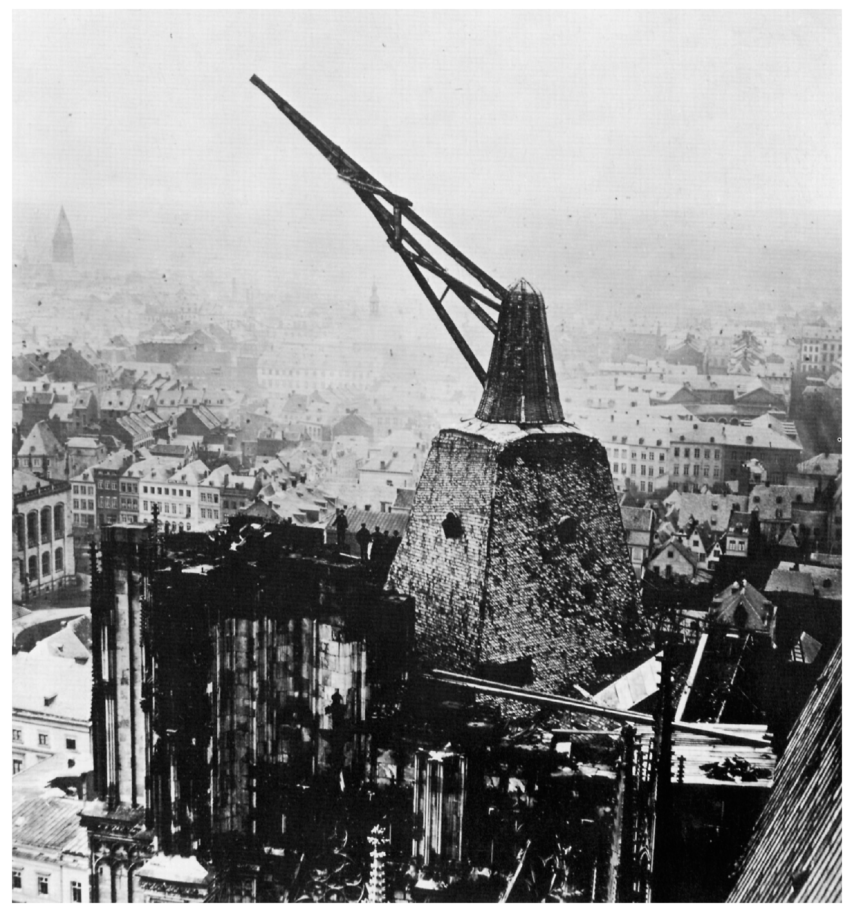
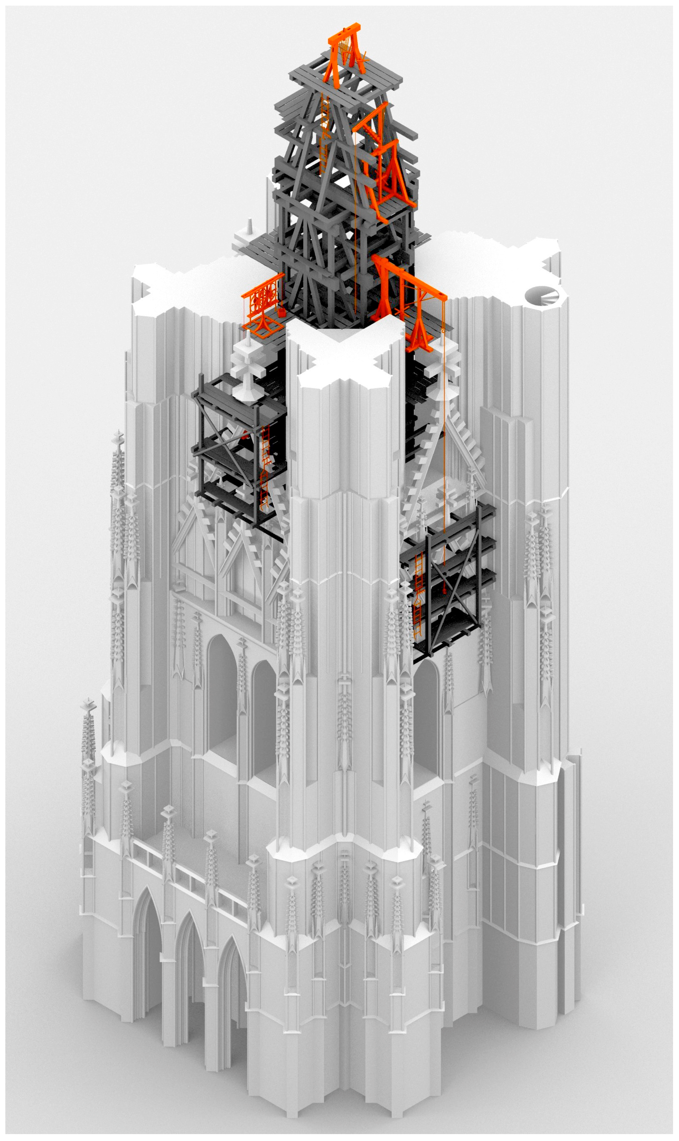
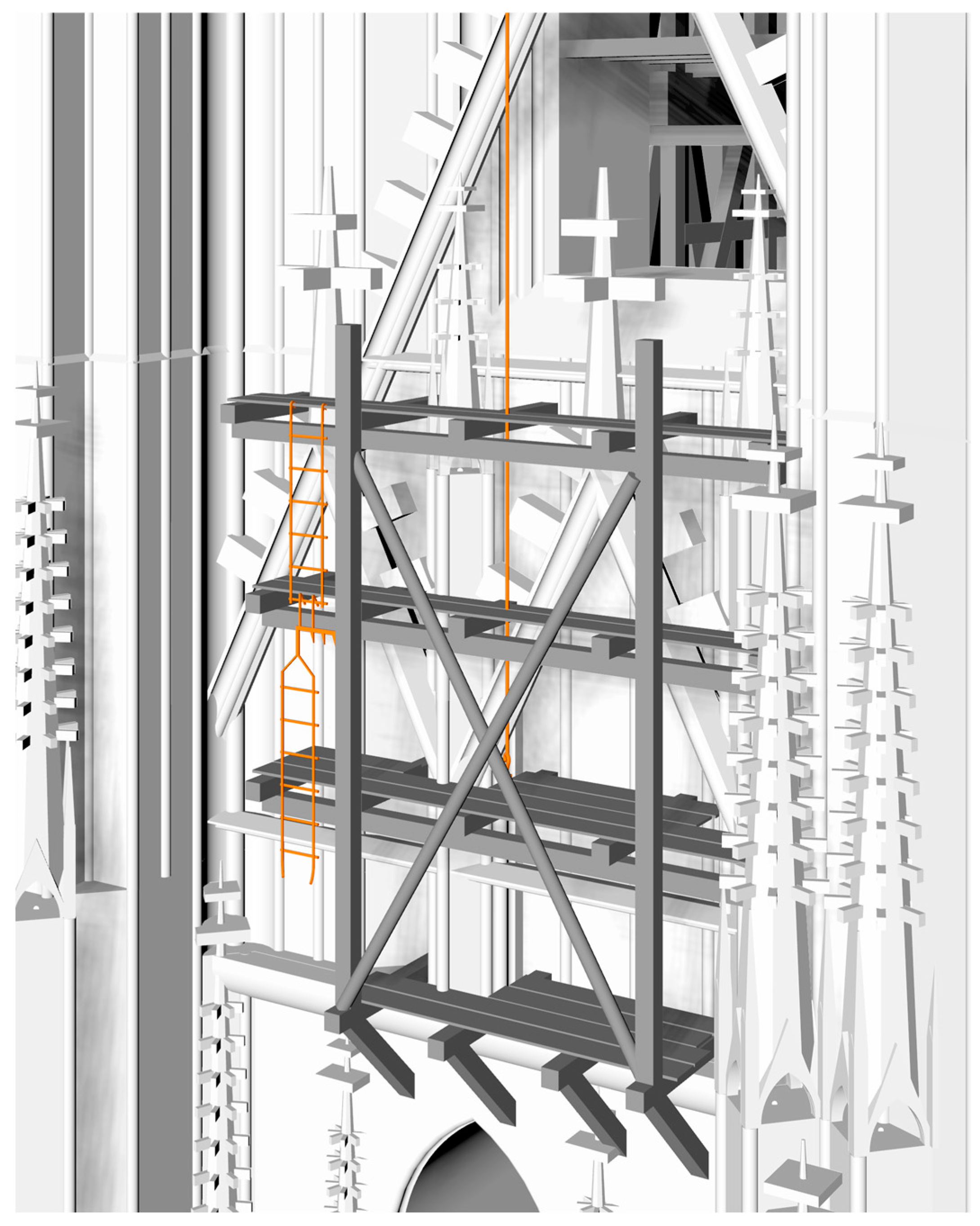
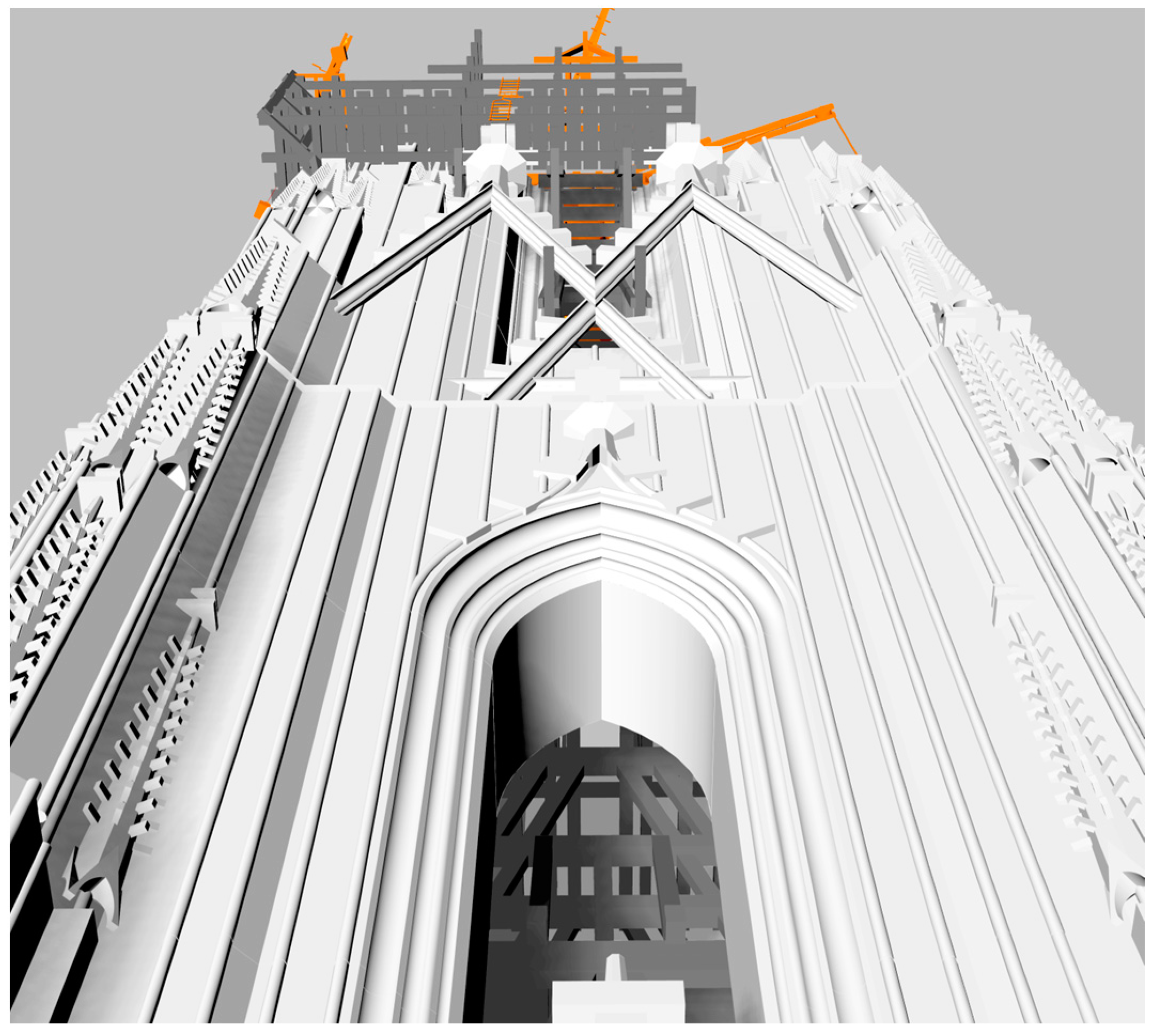
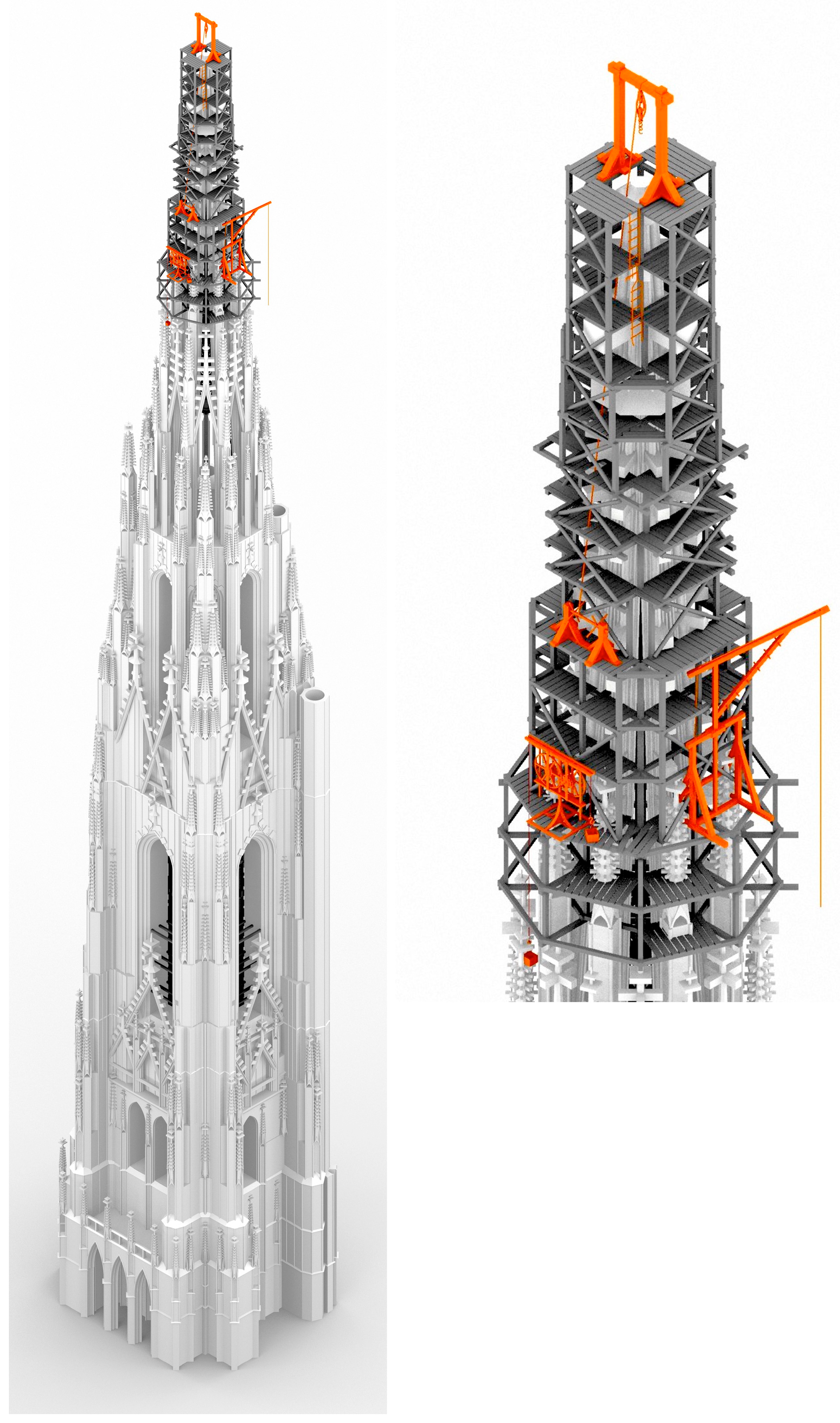
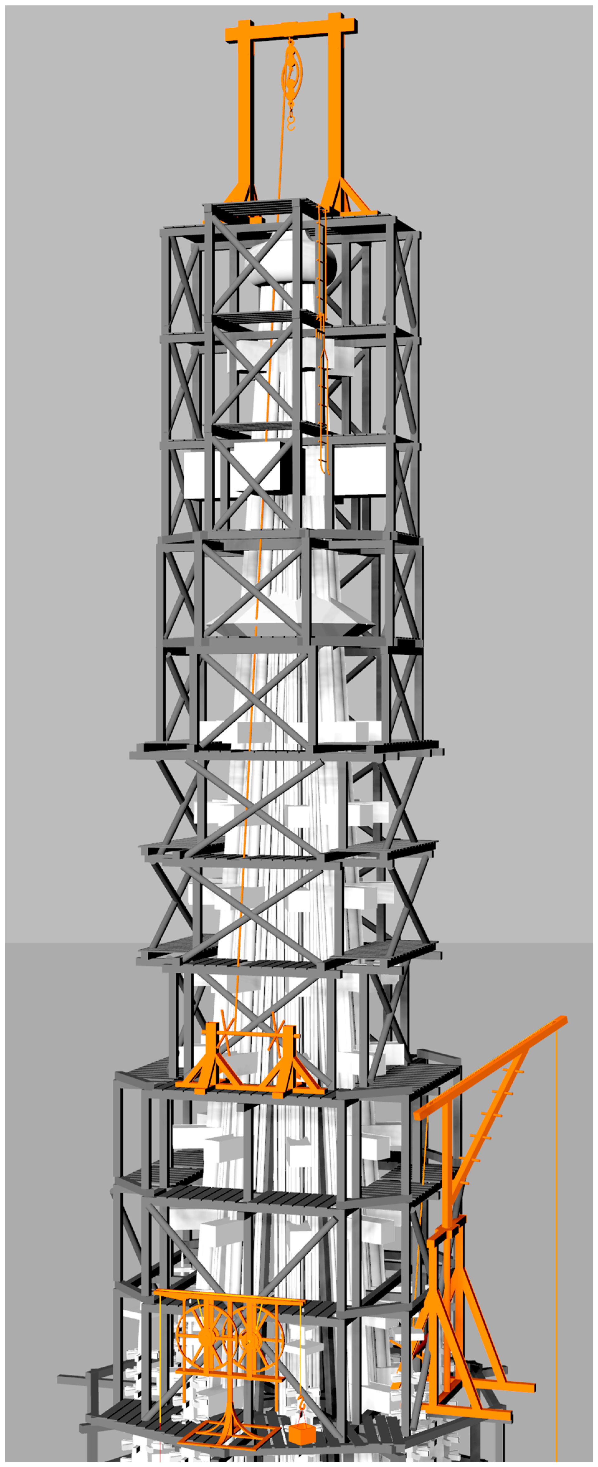