Article

Investigation towards Laser Cleaning of Corrosion Products from Lead Objects

by
Denis Prokuratov
1,2,3,*,
Andrey Samokhvalov
4,
Dmitry Pankin
5,
Oleg Vereshchagin
6,
Nikolai Kurganov
7,8,
Anastasia Povolotckaia
5,
Alexander Shimko
5,
Alexandra Mikhailova
5,
Roman Balmashnov
9,
Anastasia Reveguk
10,
Olga Smolyanskaya
2,
Dmitry Redka
11,12 and
Vjaceslavs Bobrovs
12
1
The State Hermitage Museum, 190000 St. Petersburg, Russia
2
Heritage Science Laboratory, ITMO University, 199034 St. Petersburg, Russia
3
School of Arts and Cultural Heritage, European University at St. Petersburg, 191187 St. Petersburg, Russia
4
International Scientific Laboratory of Laser Micro- and Nanotechnology, ITMO University, 197101 St. Petersburg, Russia
5
Centre for Optical and Laser Materials Research, St. Petersburg University, 198504 St. Petersburg, Russia
6
Mineralogical Department, Institute of Earth Sciences, St. Petersburg University, 199034 St. Petersburg, Russia
7
Conservation Department, Faculty of Arts, St. Petersburg University, 199004 St. Petersburg, Russia
8
Institute of the History of Material Culture of the Russian Academy of Sciences, 191186 St. Petersburg, Russia
9
Lasers & Optical Systems Co., Ltd., 199053 St. Petersburg, Russia
10
Physical Methods of Surface Investigation Resource Centre, St. Petersburg University, 198504 St. Petersburg, Russia
11
Photonics Department, St. Petersburg Electrotechnical University (“LETI”), 197022 St. Petersburg, Russia
12
Institute of Telecommunications, Riga Technical University, 1048 Riga, Latvia
*
Author to whom correspondence should be addressed.
Heritage 2023, 6(2), 1293-1307; https://doi.org/10.3390/heritage6020071
Submission received: 31 December 2022 / Revised: 23 January 2023 / Accepted: 27 January 2023 / Published: 29 January 2023
(This article belongs to the Special Issue Cleaning Strategies for Cultural Heritage)

Abstract

:
In this work lasers with micro-, nano-, pico- and femtosecond pulse durations were used to clean atmospheric corrosion products from the fragments of a 19th-century lead outdoor sculpture. The state of the surface was studied by optical microscopy, Raman spectroscopy, X-ray photoelectron spectroscopy and scanning electron microscopy. It was shown that for all lasers used there is no self-limiting cleaning effect, and the metal damage threshold is lower than the corrosion removal threshold. Using the XPS method, it has been demonstrated that the effect of turning a metallic lead surface blue after irradiation is associated with an interference effect in the PbO film. Raman spectroscopy indicated no phase changes in the corrosion layer after laser cleaning with 8 ns, 75 ps and 100 fs pulses, which makes these lasers useful for the layer-by-layer cleaning of archaeological objects.

1. Introduction

Lead is one of the first metals that became known to humans and many museums around the world store lead objects in their collections. Lead is quite well preserved in atmospheric conditions as it forms a thin oxide film which protects the base metal from any damaging influence of the environment. The main cause of lead corrosion is the presence of humidity condensed on its surface. Water serves as an electrolyte and provides a medium for dissolving the entire spectrum of the atmosphere’s gases [1,2]. By entering a condensed water drop, carbon dioxide leads to the formation of lead carbonates, primarily cerussite (PbCO3) and hydrocerussite (Pb3(CO3)2(OH)2). Upon further exposure to the atmosphere, carbonates react with sulfur dioxide (SO2) and sulfur trioxide (SO3) and form a film, which consists of a mixture of scotlandite (PbSO3) and anglesite (PbSO4). Subsequently, the main part of scotlandite is displaced, forming a protective film of anglesite [2,3]. The build-up of corrosion products eventually leads to the cracking of the surface, thereby increasing the access of contaminants to the underlying metal [4]. Atmospheric composition affects both the relative amounts of corrosion products formed and the order of their formation [5].
In the case of museum storage, volatile organic acids, mostly acetic and formic, can initiate and/or catalyze the corrosion process [6,7]. These acids come from oak or coniferous wood, used in the manufacturing of museum showcases [8]. In the presence of acetic acid vapors, lead forms lead acetate, which then turns into basic carbonate-cerussite under the action of atmospheric carbon dioxide. This process is accompanied by a further release of acid, which in turn causes a cyclic corrosion reaction of the metal up to its complete destruction. In the case of organs, the use of oak wood in their construction led to such a damaging corrosion processes that, in order to preserve organ heritage, the research project COLLAPSE (Corrosion of Lead and Lead-Tin Alloys of Organ Pipes in Europe) was realized [1,9,10].
Lead objects in museums need regular monitoring, stabilization and cleaning to extend their lifetime. Corrosion processes weaken the metal, making it brittle and sensitive to mechanical stress. Metallic lead is softer than its corrosion products: according to the Mohs scale of mineral hardness, the hardness of lead is 1.5, while the hardness of laurionite (Pb(OH)Cl), anglesite (PbSO4) and cerussite (PbCO3) is in the range of 2.5–3.5 [11]. Abrasive or harsh manual cleaning can cause a loss of an object’s fragments and leave tool marks on the surface. Even cleaning with compressed air or a pressure washer can damage soft metal [12]. With regard to the conservator, the mechanical cleaning of lead objects can be hazardous, given that lead dust is poisonous [1]. In view of all the above factors, the mechanical cleaning of lead is a rather complicated restoration procedure.
In the case of chemical cleaning, the reagents are difficult to remove completely from an object. As a result, traces of chemical agents activate processes of metal destruction [1]. Electrochemical cleaning has been successfully applied to small lead objects [7]. However, the method is quite time-consuming [13] and requires the full immersion of the object in a solution, which is impossible for monumental sculptures. An additional constraint is that only materials that have a non-aggressive nature in relation to an object, and are also safe both to a restorer as well as the environment, are recommended for restoration procedures [1].
Shortcomings of the current suite of methods dictate the need to investigate alternative techniques. The application of laser cleaning for heritage objects is very promising, since the effect of radiation is strictly localized, well controlled and can be immediately stopped. Radiation parameters can be selected individually, there is no mechanical pressure on the treated surface and this is a chemical-free technique.
Only a few papers on the laser cleaning of heritage lead objects have been published, although lead was one of the first metals that laser cleaning was applied to [14]. In the pioneering work of John Asmus in the early 1970s, a ruby laser was used to clear a section of lead strip from a XII century sarcophagus. In the work [12], a Phoenix Nd:YAG laser was used to clean a gilded lead statue, operating in a Q-switched mode (pulse duration of about 10 ns) at a wavelength of 1064 nm, which showed high efficiency. The authors claimed that the achieved results demonstrate a good level of preservation of the lead monument. In another study [15], the laser cleaning of lead coins from calcareous encrustations was carried out. The authors recommend operating with a laser fluence of 0.4–1 J/cm2 and a pulse frequency of less than 10 Hz for 2–10 ns, using a 1064 nm Nd:YAG laser. None of the three papers contain any surface examination, either with optical microscopy or SEM.
The aim of the present work is to study the processes that occur during the interaction of laser pulses of various durations with lead and its corrosion products in order to create a guideline for conservators. Laser cleaning of museum objects is rather demanding, and must meet a number of requirements. Firstly, laser irradiation should not create new artificial colors on the surface, since this changes the historical authenticity of the object. Secondly, the laser must not damage the bulk metal during corrosion removal, since this interferes with the original surface [16,17] and can activate a corrosion process. In this work a number of laser systems with different pulse lengths were used to find the proper cleaning regime and to detect a potential self-limiting cleaning effect.

2. Materials and Methods
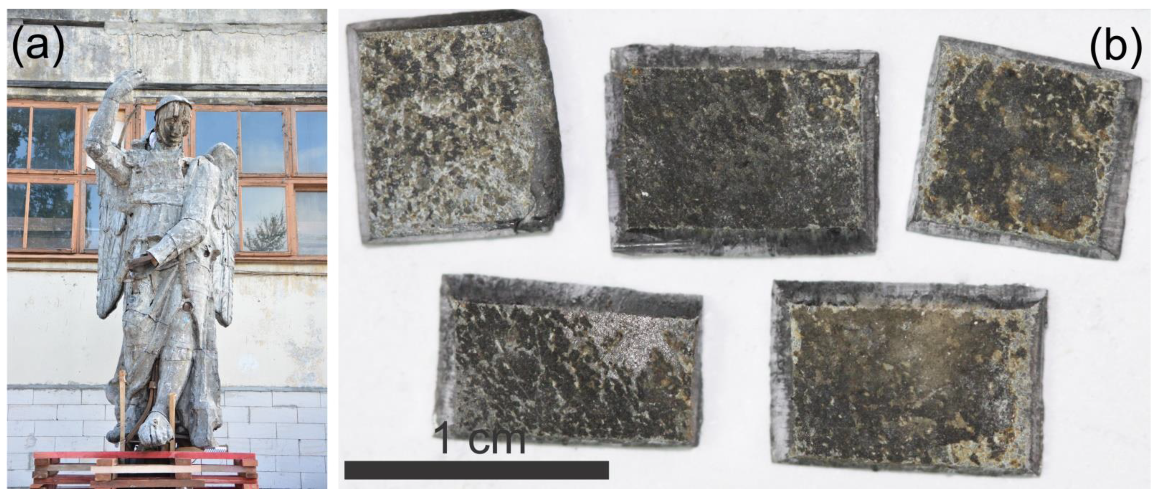
2.1. Materials

Fragments of an outdoor statue of an angel by sculptor I. P. Prokofiev, dated 1823, from the dome of Saint Catherine Church of Vasilyevsky Island in Saint Petersburg, were used as experimental samples. The 3.8 meter high sculpture was made of wood and covered with 2-mm-thick lead plates (Figure 1). Due to the destruction of both the wooden base and the lead sheets, the sculpture was dismantled and replaced with a copy. Our experiments were carried out on small fragments of the original lead sheet.

2.2. Analytical Methods and Laser Systems

Optical microscopy was used to observe the surface changes (color, topography) after irradiation. Visual appearance is the most important parameter for a museum object, because it represents the original state of cultural heritage items. Surface examination was performed using Carl Zeiss Stemi 508, Hirox-6700, Olympus BX-51 and Levenhuk D740T microscopes. To investigate the optical characteristics of the samples, UV-Vis-NIR spectroscopy was used. The surface reflection spectra were measured using a Lambda 1050 spectrophotometer (Perkin Elmer, Waltham, MA, USA) with an analytical module 150 mm InGaAs Integrating Sphere in the 250–2500 nm range with a scanning step of 2 nm, and with a 2 nm slit width.
The color change of the irradiated surface occurred for multiple reasons, such as the formation of a new substance, a change in the crystal’s size or a phase modification of initial corrosion products. To analyze the phase composition of corrosion deposits Raman spectroscopy was used. Raman spectra were obtained with a Senterra (Bruker, Billerica, MA, USA) Raman spectrometer, conjugated with an Olympus BX-51 microscope, using a 785 nm solid state laser. Due to a relatively strong luminescence, the obtained spectra were baseline corrected and normalized. X-ray photoelectron spectroscopy (XPS) was used to analyze the thin top-most surface layer on the irradiated surface. The XPS measurements were conducted with an Escalab 250Xi (Thermo Fisher Scientific, Waltham, MA, USA) photoelectron spectrometer with Al-Kα radiation (photon energy 1486.6 eV). Spectra were recorded in the constant pass energy mode at 50 eV, using XPS spot size 650 μm. Peaks were fitted with the product of asymmetric Gaussian and Lorentzian line shapes. The surface micro-topography and elemental composition analysis was performed using a TESCAN LYRA3 microscope and a Carl Zeiss EVO MA 25 microscope with the energy-dispersive X-ray detector X-MaxN 80 (Oxford Instruments, Abingdon, UK).
The lasers used in the experiments varied in pulse duration, and are listed in decreasing order in Table 1.

3. Results

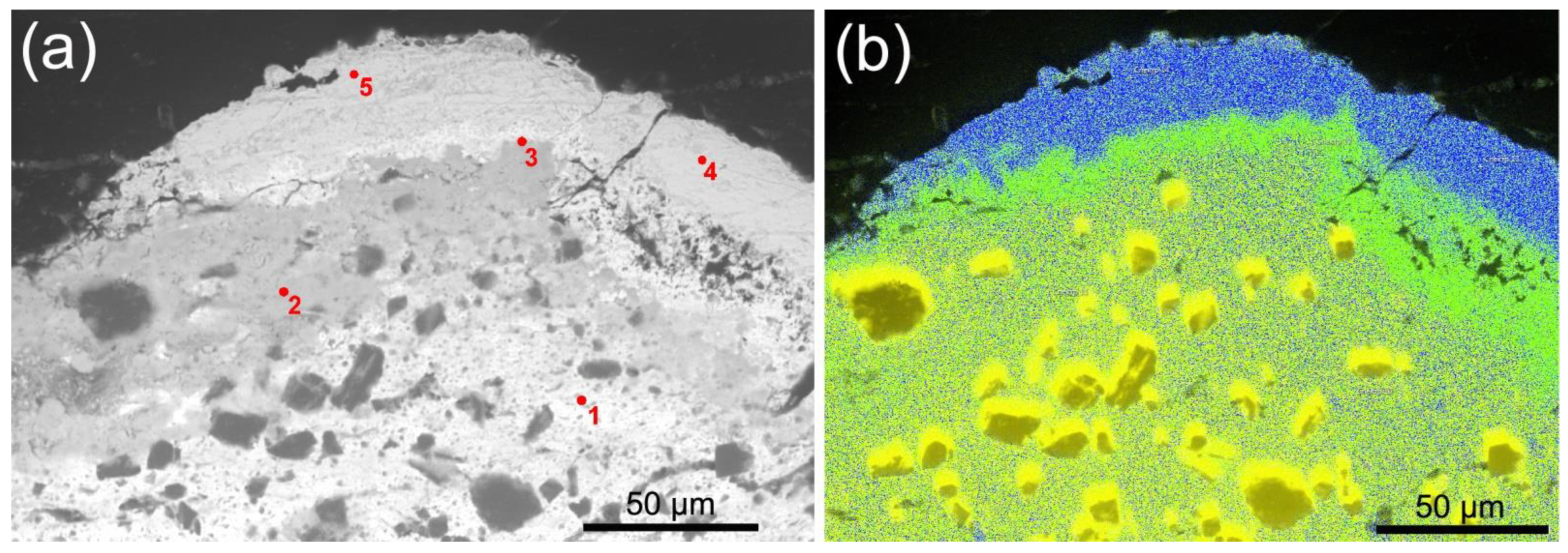
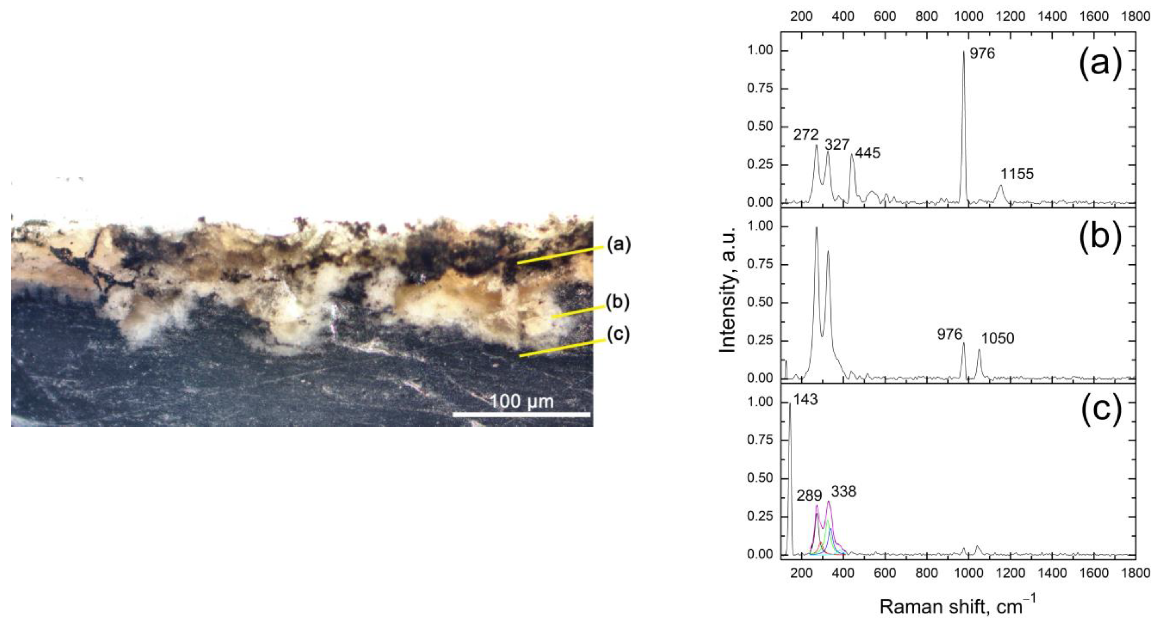
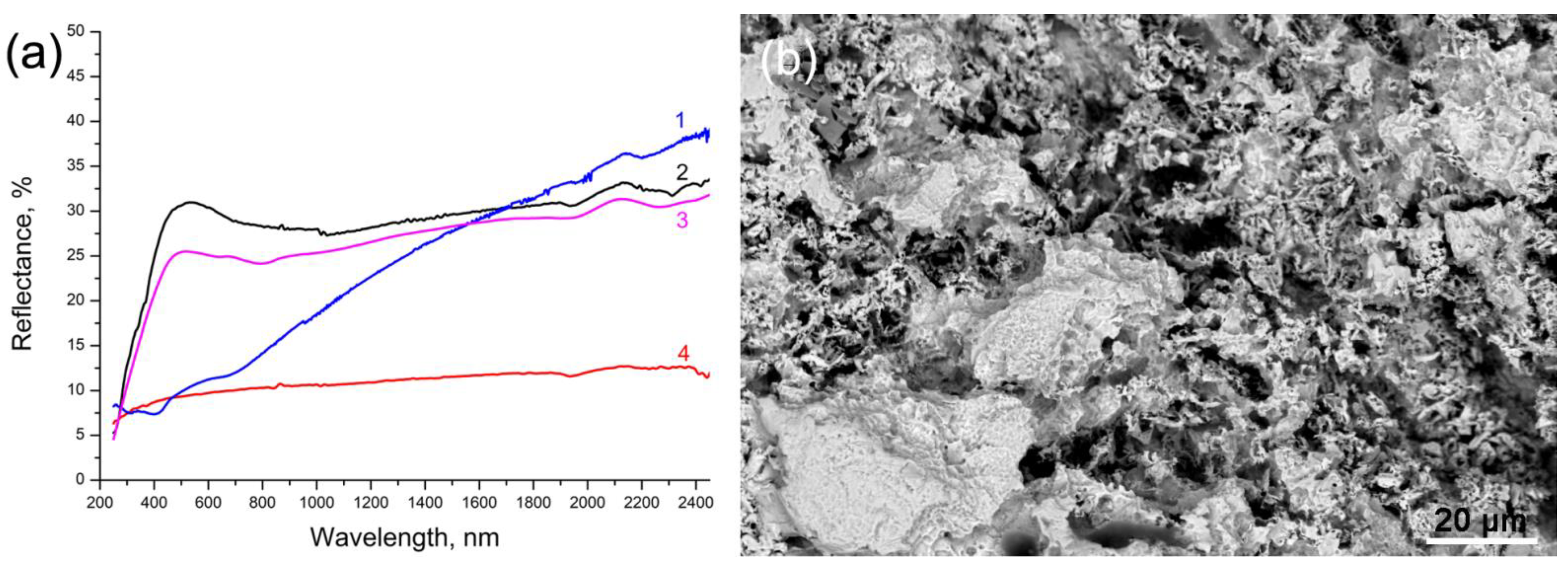
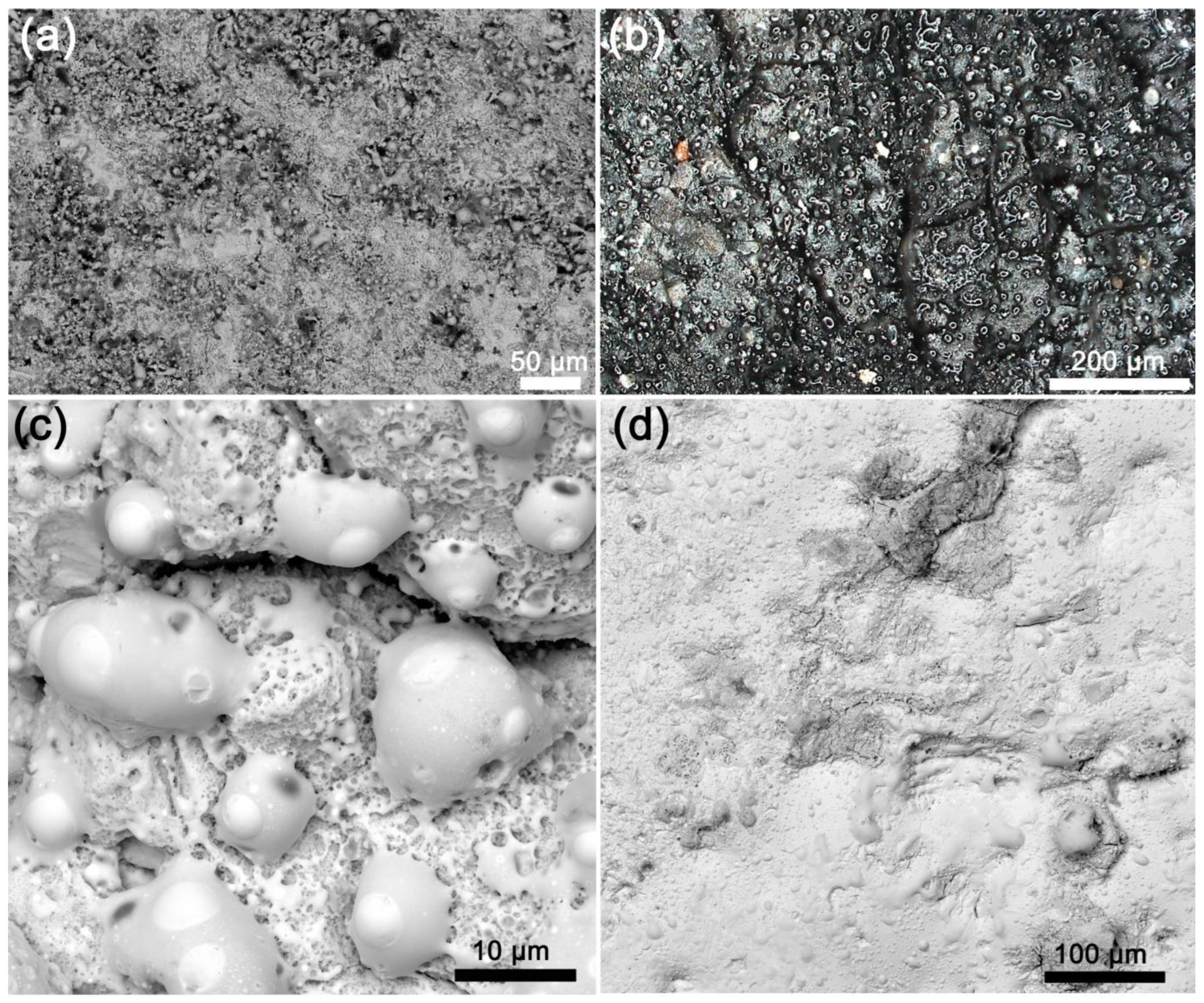
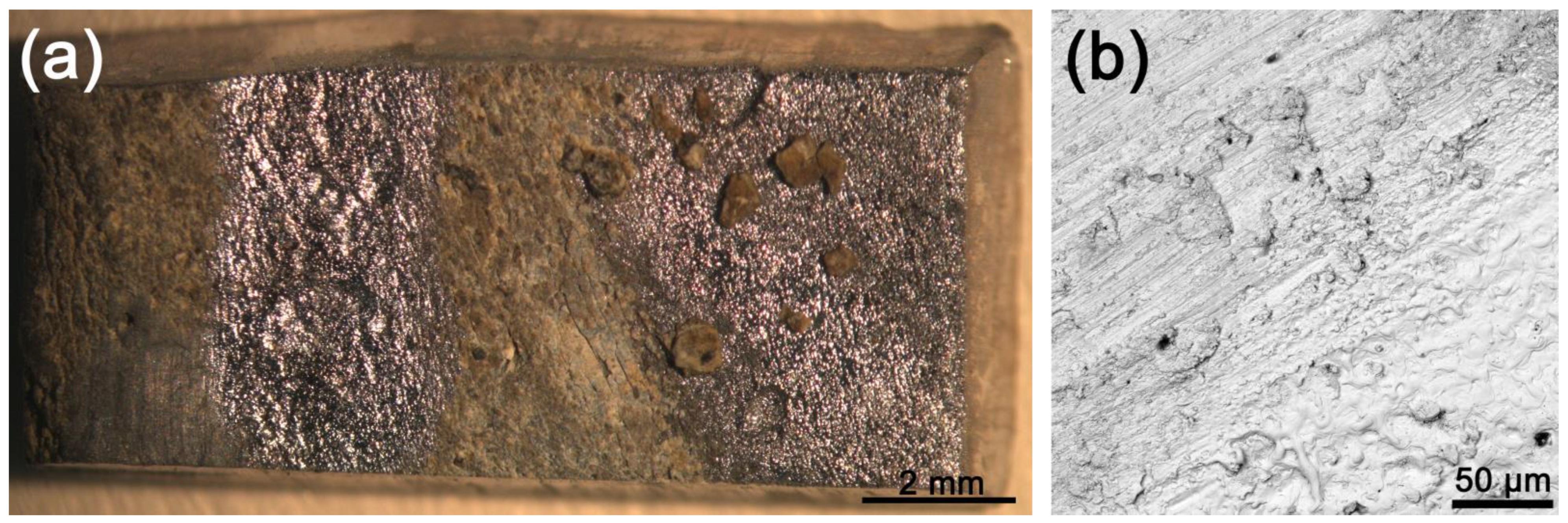
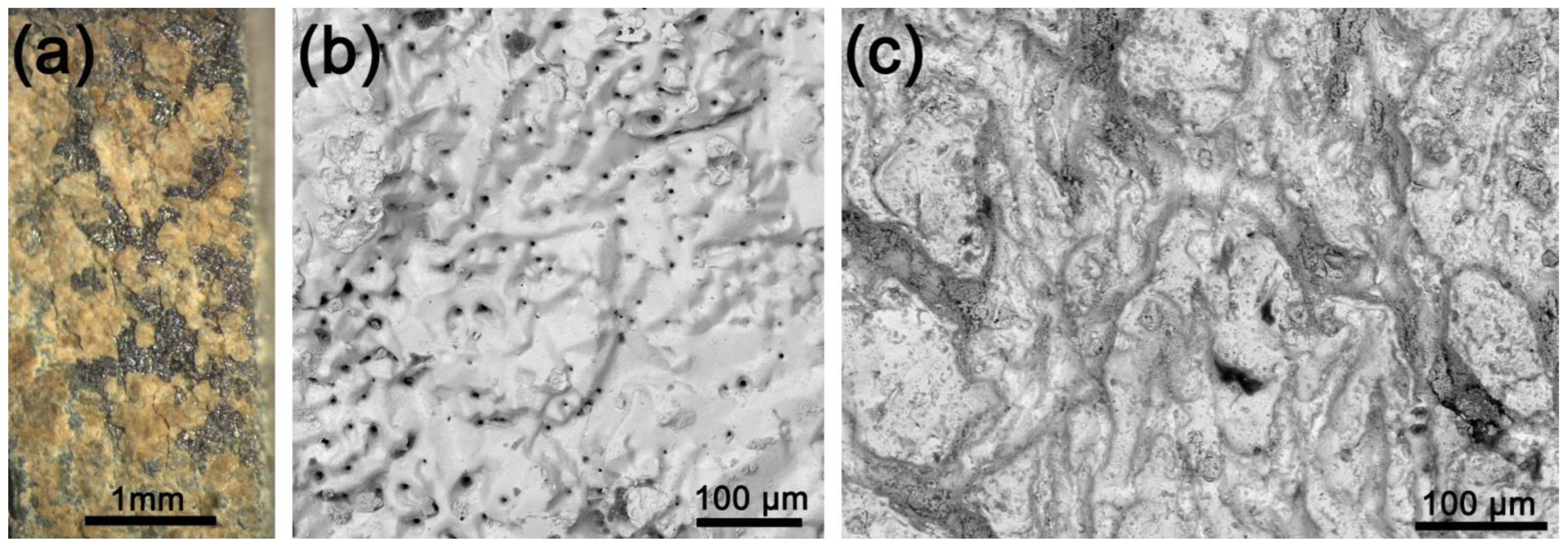
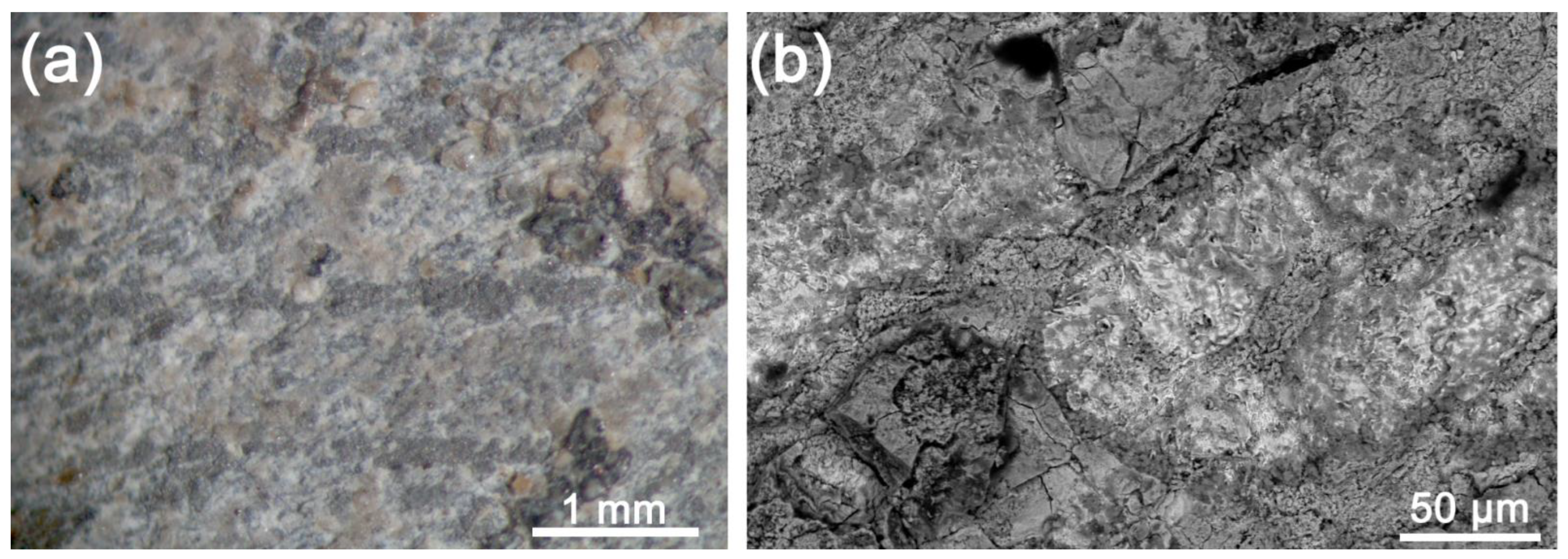
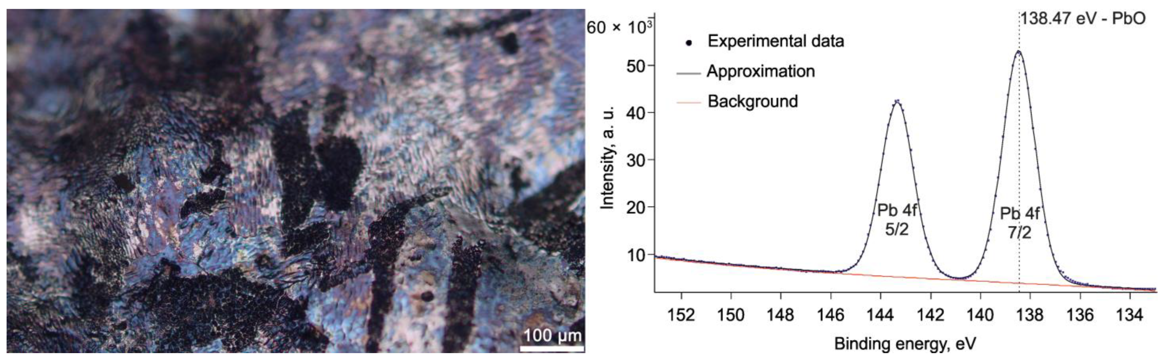
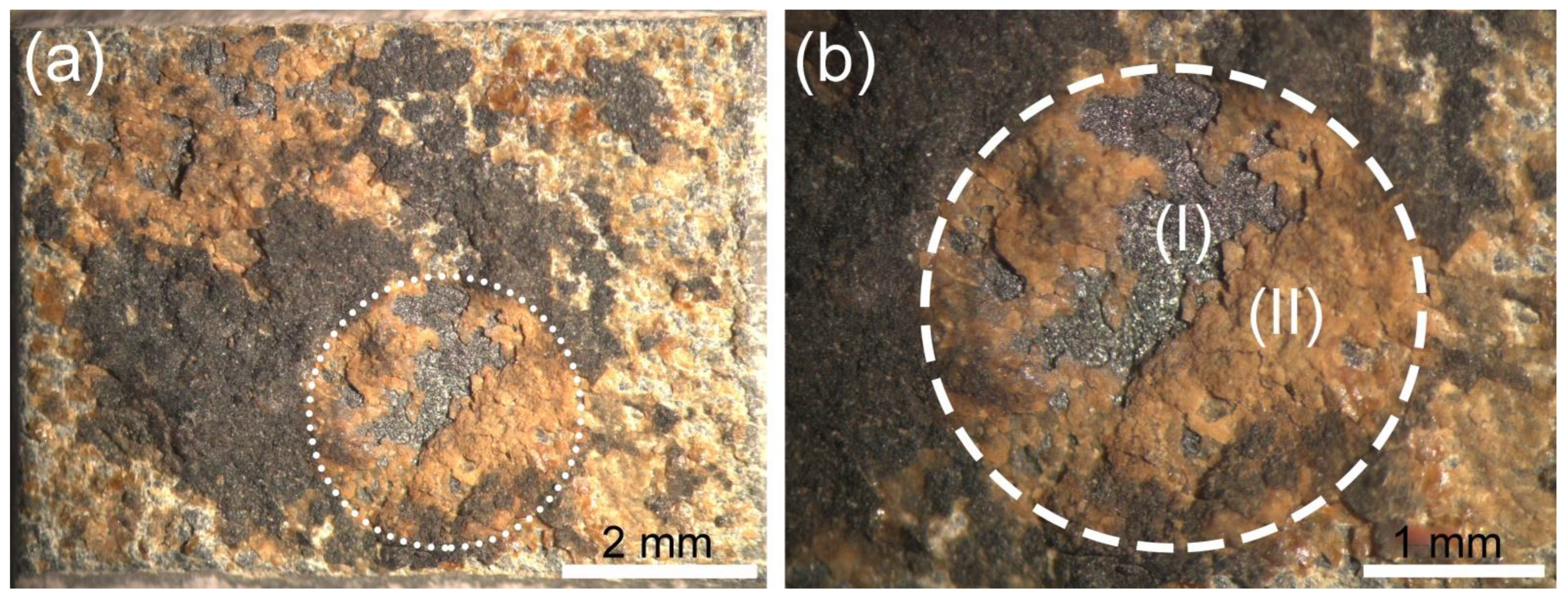
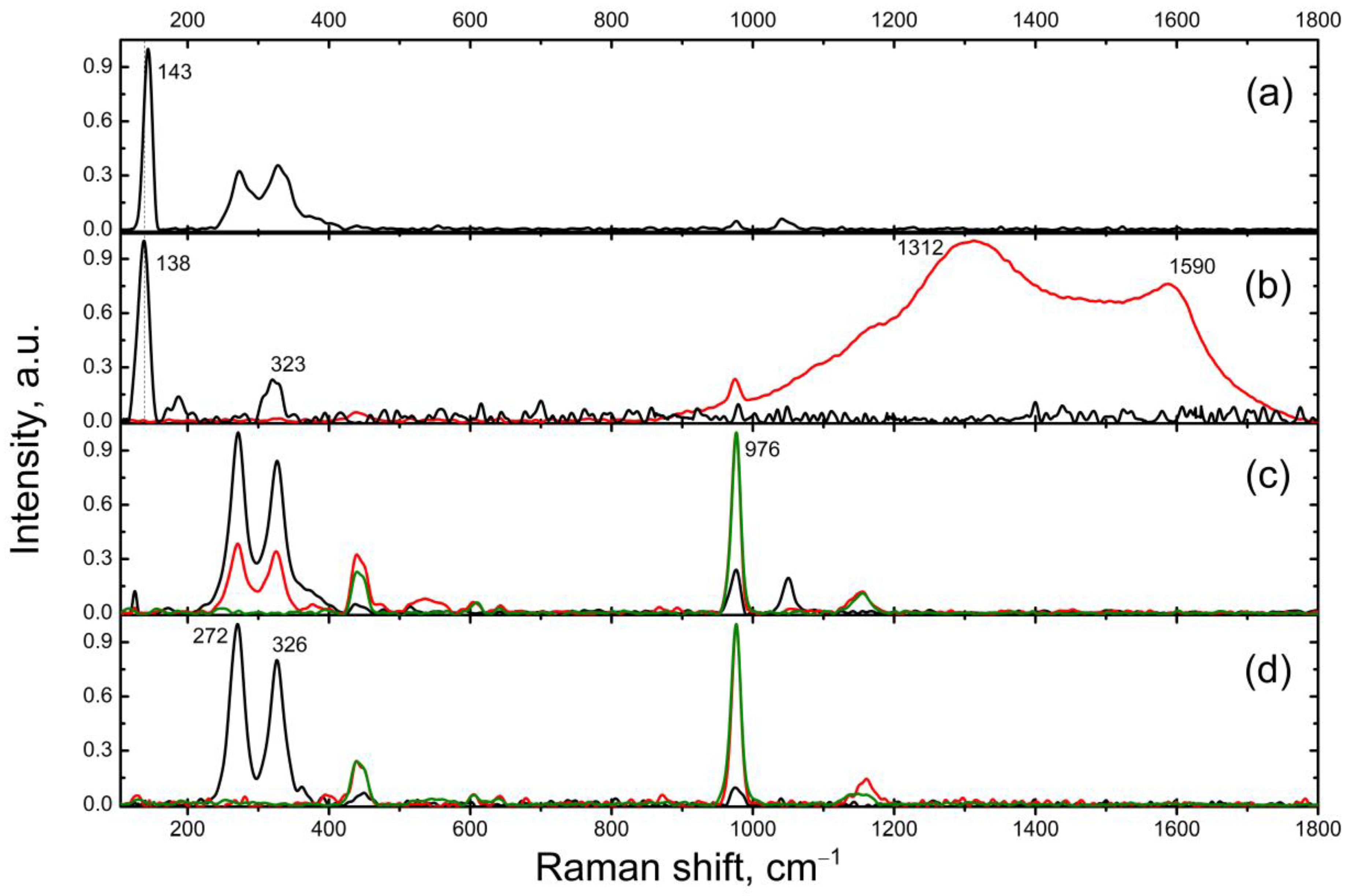
3.1. Samples Characterization

An investigation of corrosion layers includes the cross-section preparation, followed by SEM-EDX and Raman analyses. Figure 2a shows the SEM image of the cross-section with a stratigraphy of corrosion layers. Two centuries of outdoor exposure resulted in a weakening of the sculpture’s metal due to intergranular corrosion. The angular dark fragments are the remnants of abrasive paper and contain particles of Al2O3 and SiC; they were stuck in the soft metal during the cross-section creation. The SEM-EDX map (Figure 2b) shows the distribution of chlorine (green), sulfur (blue) and silicon (yellow). Table 2 represents the results of EDX analysis at several points: metallic lead (1), internal (2,3) and external (4,5) layers of corrosion products (see Figure 2a). Chlorine adjoins metallic lead, while sulfur is situated in the outer corrosion layers. The EDX analysis showed that lead was quite pure: only trace impurities of Al (0.16 wt. %) and Cu (0.10 wt. %) were detected.
As it can be seen from Figure 1b, corrosion layers differ in color. Each of the observed layers was studied by Raman spectroscopy (Figure 3). The top layer has shades from brown to black. A typical spectrum from this area is shown in Figure 3a. Its characteristic feature is the presence of an intense peak with a maximum at 976 cm−1, which is interpreted as the peak ν1 of the totally symmetric vibration in SO42− in anglesite [18,19,20]. Additional confirmation of the anglesite presence is the detection of bands, corresponding to vibrations ν2 (at 445 cm−1), ν3 (1155 cm−1) and ν4 (608 and 640 cm−1) [18,21]. The Figure 3a spectrum also shows peaks at 272 and 327 cm−1. Their intensities change concurrently but independently of anglesite peaks and, as the Figure 3b spectrum shows, they become dominant in areas with the white color. This pair of peaks is consistent with the chlorine-containing mineral laurionite. For this mineral, crystallizing with the orthorhombic space group Pnma, the peak at 327 cm−1 was assigned to phonons with the symmetry of the irreducible representation of Ag and B2g, and the peak at 272 cm−1 to B1 and B3g [22]. Additionally, the spectrum Figure 3b shows peaks at 976 and 1050 cm−1. The 976 cm−1 peak refers to anglesite, while the 1050 cm−1 peak is interpreted as the totally symmetric vibration of ν1 in the CO32− ion in hydrocerussite or cerussite [23]. Overall, comparison of the spectra clearly indicates that the white area (Figure 3b) contains significantly less anglesite than laurionite as compared with the brown area (Figure 3a). The presence of the chlorine-containing mineral laurionite in the white region, as well as small amounts of hydrocerussite, is consistent with SEM-EDX data.
The third area is a visually dark layer adjacent to the metal (Figure 3c). Its spectrum has an intense peak with a maximum at 143 cm−1, which is close to the characteristic peak of Pb–O bonds in lead oxides. The peak shape of bands in the range of 250–400 cm−1 is slightly distorted. Data fitting of the complex contour with five Lorentzian equations allowed for the identification of two more peaks, characteristic for the lead oxide—289 and 338 cm−1. These peaks are attributed to the tetragonal modification of PbO—litharge [23].
Spectral reflection coefficients were measured for the different color areas of the surface. The reflectance spectra for the original metallic lead (1) and corrosion layers of white (2), yellow (3) and black color (4) are presented in Figure 4a. To investigate the original metal surface, one of the fragments was immersed for 5 minutes in an EDTA (Ethylene Diamine Tetra Acetic, C10H14N2Na2O8·2H2O) solution, pre-heated to 90 °C. Due to two hundred years of outdoor exposure, the sculpture’s metal had degraded and formed a unique texture, which is hidden by corrosion deposits. Figure 4b shows a SEM image of this surface, where corroded metal has gained a spongy structure. The curve №1 in Figure 4a corresponds to the reflectance spectrum of this surface.
As can be seen from the graphs (Figure 4), all the layers have low reflection in the UV region. The white (2) and brown (3) corrosion layers have reflection peaks around 500 nm. The reflection coefficient of the metallic lead does not exceed 40% in the entire wavelength range and has a smooth increase towards the infrared region (Figure 4, spectrum 1). Qualitative characteristics of the colored areas observed in Raman spectra are consistent with the features observed in reflection spectra. For example, in the black area, where anglesite is abundant in Raman spectra, a shallow horizontal spectrum is observed (Figure 4, spectrum 4), which is consistent with the anglesite mineral spectrum presented in [24]. Moving to lighter colored areas, brown and white (Figure 4, spectrum 3 and 2, respectively), we observe an increase in the reflection at 400–800 nm. This is consistent with an increase in the relative concentration of laurionite and hydrocerussite, which looks bright under natural light [24].
With a multi-analytical approach to the sample study, the following sequence is obtained: a visually dark oxide layer (PbO, litharge) with the inclusion of laurionite (PbClOH) and hydrocerussite (Pb3(CO3)2(OH)2) is located closest to the lead. We consider that this layer contains the original surface layer, and so therefore with laser cleaning we need to stop at this depth. Moving outwards away from the metal layer, the dark oxide layer is followed by a white layer, which becomes thicker with a gradual increase in anglesite (PbSO4) content. Furthermore, as the percentage of anglesite increases, laurionite and hydrocerussite decrease. Areas with the highest content of anglesite have brown and black shades. Previously [5,25], the sequence of formation of various lead compounds has been studied, and even though different authors gave different orders of phase formation, the final substance in all works was anglesite. In our case, the marine air of Saint Petersburg led to the appearance of laurionite in this chain, as a result of the reaction of sodium chloride with lead oxide, as reported in [1,2]. Due to the outdoor exposure, the topmost layer of contamination contains soot/dust deposits.

3.2. Laser Cleaning Experiments

The laser cleaning experiments were carried out according to the following procedure: first, the laser-induced damage threshold of a chemically cleaned lead sample irradiated by a single pulse was determined. SEM was used for the precise detection of this damage threshold. Secondly, the corroded samples were irradiated with respect to the damage threshold of the metal. In the case of under-cleaning, firstly the number of pulses was increased. If the complete removal of corrosion products still could not be achieved, then the laser fluence was gradually increased. Irradiation was carried out in dry conditions and with the addition of water/isopropyl alcohol by wet brush. A portable ventilation system was used in all trials, since the by-products generated by the laser irradiation of lead are poisonous.
Although it is widely known that micro- and nanosecond pulses lead to sufficient heating of the surface, no negative consequences for these durations have been reported in published papers [12,14,15]. From the authors’ own experience and the published review on laser cleaning of metals [26], it follows that even similar museum objects can behave differently under the same irradiation parameters. The slight difference in composition accounts for the differences in laser absorption and removal of the corrosion layers. Therefore, irradiation with μs and ns pulses was performed.

3.2.1. Microsecond Pulses

Experiments began with EOS Combo laser irradiation of the chemically cleaned sample in free-running mode (τpulse = 30–110 μs) with a pulse energy of 100 mJ. By gradually reducing the laser spot from 10 to 4 mm, we obtained several steps of fluence from 0.12 to 0.80 J/cm2. The effect of the laser irradiation was visible to the naked eye starting from 0.35 J/cm2. However, the SEM study showed that already at fluence above 0.19 J/cm2, molten metal globules were formed on the lead surface (Figure 5a).
A corroded sample was then irradiated: at a fluence of 0.12–0.19 J/cm2 no visible cleaning effect was observed even after 100 pulses. The addition of water or isopropyl alcohol did not increase the cleaning efficiency. There was no cleaning at the fluence of 0.35–0.80 J/cm2, however black globules appeared on top of the corrosion layer (Figure 5b,c). Raman spectroscopy has shown that the globules’ composition is very heterogeneous, and three main groups can be distinguished. The first group consists of synthetic analogues of litharge with a relatively large contribution of anglesite and a small amount of amorphous carbon. The second group is qualitatively similar to the first one, except there are fewer sulfates, and a larger proportion of the amorphous phase. In the third group, globules consist almost entirely of massicot (orthorhombic PbO), with occasional litharge in small quantities.
In an attempt to complete cleaning of the lead surface from corrosion layers, the laser fluence was increased. At 0.8 J/cm2, a slight removal occurred. The number of pulses was increased to 100, but this did not lead to a complete cleaning of the metal. With a fluence of 3.2 J/cm2, all deposits were removed after 3–4 pulses; however, the surface became heavily melted. SEM image demonstrates that while lead melts, the contaminants partially integrate into melted metal (Figure 5d). The surface, weakened by the corrosion processes, develops cracks and cavities which fill up with the corrosion products. Heating, produced by high energy irradiation, seals these cavities with corrosion products inside. This process is highly undesirable in the cleaning of heritage objects. The threshold for removing corrosion deposits in this mode is noticeably higher than the threshold for lead damage.

3.2.2. 100-Nanosecond Pulses

In the Long Q-Switching mode (τpulse = 100 ns) of the EOS Combo, the pulse energy was 150 mJ, and a range of the fluence from 0.20 to 0.76 J/cm2 was tested on the chemically cleaned sample. SEM study showed traces of melting already at the minimal fluence 0.20 J/cm2.
In a corrosion layer irradiation, a slight darkening was observed at 0.2–0.3 J/cm2. This darkening was associated with the formation of dark globules, as in the case of μs pulses. Increasing the number of pulses or wetting did not lead to surface cleaning. At 0.4 J/cm2 and above, together with the darkening of the surface, a partial cleaning occurred and the metal in the cleared areas was melted. With fluence above 0.53 J/cm2, the percentage of cleaned surface was increased; however, the cleaned-to-metal areas acquired a bluish tint. As a result of further laser fluence increase (to 1.2 J/cm2, Figure 6a, right edge of the sample) the surface melted after a single pulse, but the corrosion deposits only partially remained. The laser fluence was increased to 4.7 J/cm2, and all impurities were removed, but the surface became heavily melted (Figure 6a, middle area). SEM study of the irradiated surface highlighted this aspect, which is of great importance during laser cleaning of heritage objects. Laser irradiation fuses the traces of original manufacturing tools, which is extremely undesirable in conservation (Figure 6b). The self-limiting cleaning effect, occurring in marble or limestone cleaning [14], was not observed here. In the lead case, after reaching the metal base, ablation intensifies, the plasma jet becomes brighter, and the ablation sound gets louder. The water-assisted cleaning mode, recommended in [15], did not prevent surface melting in either EOS Combo laser regimes. Therefore, it is recommended to avoid both regimes of the EOS Combo laser in lead object cleaning.

3.2.3. 6–8-Nanosecond Pulses

In the trials with SpitLight laser, irradiation was performed in the fluence range from 0.02 to 0.4 J/cm2 with 20 mJ pulse energy. SEM studies showed that chemically cleaned lead melting started from 0.06 J/cm2. When a corroded sample was irradiated at 0.06 J/cm2, no cleaning was observed. The number of pulses was increased to 100, but there was no cleaning effect. The addition of water or isopropyl alcohol also did not increase the cleaning efficiency. When laser fluence was increased to 0.2 J/cm2 a noticeable removal of corrosion layers occurred, but in the cleaned areas lead was melted (Figure 7a). Fluence was increased, and with 100 pulses at 0.4 J/cm2 the corrosion deposits were completely removed, but the SEM indicates that traces were integrated into the melted metal (Figure 7b).
The irradiation experiments demonstrate that lead corrosion layers have different local densities and adhesion to the metal surface. The very top layers of contaminants which are formed by soft corrosion products and soot/dust pollution can be removed quite easily with several pulses. In the areas where contaminants are soft and have weak adhesion to the metal, the surface can be successfully cleaned by laser irradiation. In the areas where the corrosion layers are thicker, harder and have stronger adhesion to the metal, the laser cannot clean the surface completely.

3.2.4. Picosecond Pulses

532 nm, 63 ps

In the experiments with picosecond laser, the first trials were performed at 532 nm. The laser spot diameter was constant (3 mm), while pulse energy varied. The chemically cleaned sample was irradiated in the fluence range of 0.004–0.030 J/cm2. SEM studies showed that surface melting starts from 0.030 J/cm2. When the corrosion layer was irradiated, only at a fluence of 0.065 J/cm2 did partial removal begin. An increase in the number of pulses or wetting of the surface did not improve cleaning efficiency. Thus, only by doubling the metal damage threshold was the removal of the corrosion layer achieved.

1064 nm, 76 ps

At a wavelength of 1064 nm, when the chemically cleaned sample was irradiated, SEM studies showed melting at 0.01 J/cm2. The corroded sample was irradiated in the range from 0.005 to 0.070 J/cm2, and only at 0.06 J/cm2 did deposits begin to be removed. For the complete cleaning of the surface, around 50 pulses were needed at 0.14 J/cm2. Under these conditions, melting and flattening of the surface was observed by SEM (Figure 7c).

3.2.5. Femtosecond pulses

The femtosecond laser system has a constant pulse frequency of 10 Hz. To determine the threshold for metal damage, it is necessary to obtain a single crater; therefore, the sample was moved by a motorized translation stage at a 2 mm/s speed. By reducing the beam energy with a discrete attenuator, 7 crater tracks were obtained with a laser fluence of 0.07–1.10 J/cm2. With SEM studies, it was shown that the single pulse at 0.07 J/cm2 did not cause the lead to melt. When a corroded sample was irradiated at 0.07 J/cm2, no cleaning was observed. As the initial irradiation of the corrosion layer under these conditions did not reveal any sign of melting, the speed of the translation stage was reduced to 0.1 mm/s. With the size of the laser spot about 300 μm and a 10 Hz pulse frequency, there are approximately 30 laser pulses per spot. Unfortunately, the results confirmed previous laser experiments: in areas where the local removal of corrosion layers occurred, metal melting was observed (Figure 8a). Due to the differences in the nature of radiation absorption, femtosecond radiation energy is more strongly absorbed by the metal than by the oxide layer [27]. This leads to explosive melting of the metal base (see Figure 8b), although the zone of thermal effect of the fs-laser radiation is much smaller than with longer pulses.

4. Discussion

It was found that for all lasers used in the study, the metallic lead melting threshold is lower than the corrosion layer removal threshold. This may be the result of one or a combination of the following factors:
  • The spectral reflection coefficients at 1064 nm for metal lead and corrosion layers are almost the same, and approximately 30% (Figure 4). This means that they absorb laser radiation equally well;
  • Some part of the incident radiation is effectively scattered and reflected at the surfaces of corrosion layer grains; this leads to a decrease in the absorbed energy;
  • Lead has a low melting point (327.5 °C). As the bonding energy of the corrosion layers is quite high, the laser energy used is not sufficient to remove the corrosion layers but generates enough heat to melt the metal;
  • The heat capacity of the irradiated materials is quite different. The heat capacity of lead is quite low—0.13 kJ/(kg·K), and a relatively small amount of heat is required to melt it. For comparison, the heat capacities of cerussite and anglesite are (330 J/(kg·K)) and (344 J/(kg·K)), respectively [28];
  • The thermal conductivity of lead is relatively low. During the laser heating, the near-surface layer gets overheated and, as the heat does not have time to transfer to the inner layers, this results in metal melting. The thermal conductivity of the corrosion layer is even lower, but due to the optical properties, absorption occurs mainly in the metal.
Melting of the lead surface during laser cleaning destroys the protective lead oxide layer. As a result, the surface becomes chemically active and corrosion processes can accelerate. To avoid this, the surface should be passivated after cleaning. The surface details, including the traces of the manufacturer’s tools, can also be destroyed, which is highly undesirable in the case of cultural heritage objects. In our experiments the μs and 100-ns pulses caused a significant melting effect. In addition, the lead fumes produced are harmful to the operator, so a proper ventilation system should be always in place.
In all the irradiation experiments it was impossible to achieve the selective cleaning of the corrosion layer, based on its composition. The non-uniform cleaning occurs due to an uneven density of corrosion deposits and their different adhesion to the bulk lead. With the lasers used it was also impossible to stop the treatment on the original surface, since there was no perceptible difference for the laser beam.
The atmospheric corrosion of lead results in the formation of caverns. Corrosion products anchor tightly in these caverns. During laser cleaning at high energy densities, the remaining corrosion products fuse into the metal base, which is highly undesirable. To prevent this, high energy densities should be avoided, or chemicals should be used in the final stage of surface cleaning after laser irradiation.

4.1. Surface’s Discoloration

4.1.1. Blue Discoloration

With all lasers, straight after melting, the surface acquires a blue color (Figure 9, left). This blue coloring has not been described in previous publications on lead laser cleaning. Since Raman spectroscopy detected only metallic lead in the blue areas, XPS was used to investigate the chemical composition of the irradiated regions (Figure 9, right). The XPS spectrum shows a pair of peaks, characteristic for the spin-orbit splitting of the 4f level of lead and corresponding to the quantum numbers 7/2 and 5/2. The peak energy (138.47 eV for Pb 4f7/2) indicates that the entire surface layer in the blue region consists of the native lead oxide PbO [29]. Therefore, the blue color of the surface appears not due to the presence of colored chemical substance(s), but rather is caused by light interference in the thin lead oxide film. In a few months after irradiation, the blue color became less noticeable, and disappeared completely on several samples.

4.1.2. Yellow Discoloration

In the case of picosecond pulse irradiation, the cleaning resulted in an apparent yellow discoloration of corrosion layers (Figure 10a). Figure 10b shows a fragment of the surface, exposed to 10 pulses at 0.06 J/cm2. Several effects can be noted: (1) the upper black layer, formed by soot and dust pollution from the atmosphere, was removed (Figure 10b, region II); (2) corrosion layers were partially removed down to the metal (Figure 10b, region I); (3) the remaining part of the corrosion layers appear yellowed. To determine if the yellowing had actually occurred, this area was analyzed using Raman spectroscopy (Figure 11).
The spectrum for area I in Figure 10b has a relatively intense peak with a maximum at 138 cm−1 (Figure 11b). It is unsymmetrically broadened from the low frequency side. Compared to the spectrum for the non-irradiated lead (Figure 11a), a shift to the low-frequency area by about 5 cm−1 and an additional peak at 323 cm−1 are observed, which may be due to the thermal effect of irradiation on the lead oxide film [23]. Additionally, the spectrum in Figure 11b shows the emergence of intense bands characteristic of amorphous carbon, namely peaks D (1312 cm−1) and G (1590 cm−1): the black spectrum corresponds to the area with oxide layer and the red spectrum corresponds to the area with high amorphous carbon content. This is a typical result of organic matter undergoing thermal damage, which in the Raman spectrum of the non-irradiated lead gave weak unidentified peaks with a strong luminescence. The background was subtracted during the data processing for better visualization of the signal.
For region II in Figure 10b, where yellowing is expected, Raman spectra do not highlight any significant difference in composition before and after irradiation (Figure 11c,d). The Raman analysis spot was 20 μm. This allowed differentiation in the yellow region grains of white, yellow and brown color (black, red and green curves, respectively, Figure 11c,d). The yellow grains contain anglesite, identified by a characteristic peak at 976 cm−1, while the white grains contain laurionite, identified by a characteristic pair of peaks at 272 and 326 cm−1. The peaks’ maxima and their full width at half maximum (FWHM) values without and after irradiation were in agreement with the corresponding parameters within the defined error limits, e.g., for anglesite (FWHM = 15 ± 1 cm−1) and laurionite (FWHM ≈ 25 ± 1 cm−1 for peak 272 ± 1 cm−1, FWHM ≈ 23 ± 2 cm−1 for peak 327 ± 1.5). Based on this, it can be concluded that the areas without and after irradiation have a qualitatively close composition. Thus, laser cleaning leads to a partial removal of corrosion layers formed by anglesite and laurionite, without any change in the actual color of the remaining layers.

5. Conclusions

This study addresses the effects of laser irradiation on a XIX-century outdoor lead sculpture. The effects of pulse duration and laser fluence on the morphology, composition and color of corrosion layers and the base metal were investigated.
It was found that for all lasers used in the study, the metallic lead damage threshold is lower than the corrosion layer removal threshold. Furthermore, there is no self-limiting cleaning effect for the lead atmospheric corrosion deposits and it is impossible to stop the ablation at the original surface. Laser irradiation performs a non-uniform surface cleaning due to the inhomogeneous density and adhesion to metal of the corrosion layers.
In the case of μs and ns pulses, black globules of mixed composition form on the top of the corrosion layer. The shorter laser pulses do not change the phase composition of the corrosion layer, which is confirmed by Raman spectroscopy studies. This aspect may be important in laser cleaning of archaeological objects, which are covered with a dense layer of corrosion deposits. The benefit of lasers for archaeological lead object cleaning is that, unlike cleaning with hand tools, it does not exert mechanical pressure on the surface being cleaned.

Author Contributions

Conceptualization D.P. (Denis Prokuratov), methodology, D.P. (Denis Prokuratov); writing—original draft, D.P. (Denis Prokuratov) and D.P. (Dmitry Pankin); writing—review and editing, D.P. (Denis Prokuratov), D.R. and V.B.; investigation, A.S. (Andrey Samokhvalov), D.P. (Dmitry Pankin), O.V., N.K., A.P., A.S. (Alexander Shimko), A.M., R.B., A.R. and O.S.; funding acquisition, O.S. All authors have read and agreed to the published version of the manuscript.

Funding

This research was carried out with the support of a grant under the Decree of the Government of the Russian Federation No. 220 of 9 April 2010 (Agreement No. 075-15-2021-593 of 1 June 2021).

Data Availability Statement

Not applicable.

Acknowledgments

The authors are thankful to colleagues from the State Hermitage Museum: Yuri Spiridonov for the photographs on the Hirox microscope, Nikolai Malinovsky for making the cross-section and its macro-photo, and Veronika Wirth for editing. We express our gratitude to the restoration workshop Nasledie Ltd. for a kindly provided photo of the angel sculpture and to Pavel Somov (TESCAN Ltd.) for the SEM images at LYRA3 microscope. In this work the equipment of the Resource Centers for Optical and laser materials research and Physical Methods of Surface Investigation at St. Petersburg University (SPbU) were used.

Conflicts of Interest

The authors declare no conflict of interest.

References

  1. De Keersmaecker, M.; Dowsett, M.; Adriaens, M. How to Preserve Lead Artifacts for Future Generations. In Chemical Interactions between Cultural Artefacts and Indoor Environment; Adriaens, M., Bioletti, S., Rabin, I., Eds.; ACCO: Leuven, Belgium; The Hague, The Netherlands, 2018; pp. 215–244. [Google Scholar]
  2. Graedel, T.E. Chemical mechanisms for the atmospheric corrosion of lead. J. Electrochem. Soc. 1994, 141, 922–927. [Google Scholar] [CrossRef]
  3. Costa, V.; Urban, F. Lead and its alloys: Metallurgy, deterioration and conservation. Stud. Conserv. 2005, 50 (Suppl. 1), 48–62. [Google Scholar] [CrossRef]
  4. Schotte, B.; Adriens, A. The treatment of corroded lead artefacts: An Overview. Stud. Conserv. 2006, 51, 297–304. [Google Scholar] [CrossRef]
  5. Tranter, G.C. Patination of Lead: An Infra-Red Spectroscopic Study. Br. Corros. J. 1976, 11, 222–224. [Google Scholar] [CrossRef]
  6. Shemakhanskaya, M.S. Metals and Things; Indrik: Moscow, Russia, 2016; pp. 133–134. (In Russian) [Google Scholar]
  7. Allen, G.C.; Black, L. Role of organic acids in lead patination. Br. Corros. J. 2000, 35, 39–42. [Google Scholar] [CrossRef]
  8. Heath, D.; Martin, G. The corrosion of lead and lead/tin alloys occurring on Japanese lacquer objects. Stud. Conserv. 1988, 33 (Suppl. 1), 137–141. [Google Scholar] [CrossRef]
  9. Niklasson, A.; Johansson, L.-G.; Svensson, J.-E. Atmospheric corrosion of historical organ pipes: Influence of acetic and formic acid vapour and water leaching on lead. In Proceedings of the International Conference on Metals Conservation, Canberra, Australia, 4–8 October 2004; pp. 273–280. [Google Scholar]
  10. Justo-Estebaranz, A.; Herrera, L.K.; Sigüenza, B.; de Haro, M.C.J.; Justo, A.; Laguna, O. Study of the corrosion products of the lead blocks from the historical organ Jean Pierre Cavaillé of Vinça, France. In Science and Technology for the Conservation of Cultural Heritage, 1st ed.; Rogerio-Candelera, M.A., Lazzari, M., Cano, E., Eds.; CRC Press: London, UK, 2013; pp. 131–134. [Google Scholar]
  11. Palache, C.; Berman, H.; Frondel, C. The System of Mineralogy of J.D. Dana and E.S. Dana, 7th ed.; Wiley: New York, NY, USA, 1951; p. 322. (In Russian) [Google Scholar]
  12. Naylor, A. Conservation of the eighteenth century lead statue of George II and the role of laser cleaning. J. Cult. Herit. 2000, 1, 145–149. [Google Scholar] [CrossRef]
  13. Dickens, J.; Smith, N.; Gerritsen, W. On again, off again: Cathodic protection of a lead and ceramic water closet during desalination. In Proceedings of the International Conference on Metals Conservation, Canberra, Australia, 4–8 October 2004; pp. 465–483. [Google Scholar]
  14. Asmus, J.F.; Murphy, C.G.; Munk, W.H. Studies on the interaction of laser radiation with art artifacts. In Proceedings of the Developments in Laser Technology II of the Annual Technical Symposium, San Diego, CA, USA, 27–29 August 1974. [Google Scholar] [CrossRef]
  15. Pini, R.; Siano, S.; Salimbeni, R.; Pasquinucci, M.; Miccio, M. Tests of Laser Cleaning on Archeological Metal Artefacts. J. Cult. Herit. 2000, 1, 129–137. [Google Scholar] [CrossRef]
  16. Bertholon, R. The location of the original surface, a review of the conservation literature. In Proceedings of the ICOM-CC Metals Working Group, Santiago, Chile, 2–6 April 2001; pp. 167–179. [Google Scholar]
  17. Korenberg, C.; Baldwin, A. Laser cleaning tests on archaeological copper alloys using an Nd:YAG laser. Laser Chem. 2006, 2006, 075831. [Google Scholar] [CrossRef]
  18. Buzgar, N.; Buzatu, A.; Sanislav, I.V. The Raman study on certain sulfates. Geology 2009, LV 1, 5–23. [Google Scholar]
  19. Miyake, M.; Minato, I.; Morikawa, H.; Iwai, S.-I. Crystal structures and sulphate force constants of barite, celestite, and anglesite. Am. Min. 1978, 63, 506–510. [Google Scholar]
  20. Lee, P.; Huang, E.; Yu, S.; Chen, Y. High-Pressure Raman Study on Anglesite. World J. Condens. Matter Phys. 2013, 3, 28–32. [Google Scholar] [CrossRef] [Green Version]
  21. Sawchuk, K.; O’Bannon, E.F., III; Vennari, C.; Kavner, A.; Knittle, E.; Williams, Q. An infrared and Raman spectroscopic study of PbSO4-anglesite at high pressures. Phys. Chem. Miner. 2019, 46, 623–637. [Google Scholar] [CrossRef]
  22. Lutz, H.D.; Beckenkamp, K.; Peter, S. Laurionite-type M(OH)X (M=Ba, Pb; X=Cl, Br, I) and Sr(OH)I. An IR and Raman spectroscopic study. Spectrochim. Acta A Mol. Biomol. Spectrosc. 1995, 51, 755–767. [Google Scholar] [CrossRef]
  23. Burgio, L.; Clark, R.J.H.; Firtha, S. Raman spectroscopy as a means for the identification of plattnerite (PbO2), of lead pigments and of their degradation products. Analyst 2001, 126, 222–227. [Google Scholar] [CrossRef] [PubMed]
  24. McConachy, T.F.; Yang, K.; Boni, M.; Evans, N.J. Spectral reflectance: Preliminary data on a new technique with potential for non-sulphide base metal exploration. Geochem. Explor. Environ. Anal. 2007, 7, 139–151. [Google Scholar] [CrossRef]
  25. Black, L.; Allen, G.C. Nature of lead patination. Br. Corros. J. 1999, 34, 192–197. [Google Scholar] [CrossRef]
  26. Bertasa, M.; Korenberg, C. Successes and challenges in laser cleaning metal artefacts: A review. J. Cult. Herit. 2022, 53, 100–117. [Google Scholar] [CrossRef]
  27. Rode, A.V.; Baldwin, K.G.H.; Wain, A.; Delaporte, P.H. Ultrafast lasers for conservation of heritage artefacts. AICCM Bull. 2006, 30, 17–26. [Google Scholar] [CrossRef]
  28. Waples, D.W.; Waples, J.S. A Review and Evaluation of Specific Heat Capacities of Rocks, Minerals, and Subsurface Fluids. Part 1: Minerals and Nonporous Rock. Nat. Resour. Res. 2004, 13, 97–122. [Google Scholar] [CrossRef]
  29. Thermo Fisher Scientific, Analytical Equipment and Instruments. Available online: https://www.thermofisher.com/ru/ru/home/materials-science/learning-center/periodic-table/other-metal/lead.html (accessed on 30 December 2022).
Figure 1. (a) Sculpture of an angel, showing intense corrosion features (photo provided by the Nasledie Ltd. restoration workshop). (b) Macro-photo of lead plate fragments.
Heritage 06 00071 g001
Figure 2. (a) SEM image of the cross-section, numbers correspond to analysis listed in Table 2. (b) SEM-EDX map of the same area, showing the distribution of chlorine (green), sulfur (blue) and silicon (yellow).
Heritage 06 00071 g002
Figure 3. Macro-photo of the cross-section (left). The Raman spectra of different corrosion layers (right): black-brown (a); white (b); and dark, adjacent to metallic lead (c).
Heritage 06 00071 g003
Figure 4. (a) Reflection spectra of various surface areas: chemically cleaned lead (1); white (2), brown (3) and black (4) corrosion layers. (b) SEM image of the chemically cleaned lead surface.
Heritage 06 00071 g004
Figure 5. (a) SEM image of chemically cleaned lead surface, irradiated with a single pulse at 0.19 J/cm2. (b) Macro-photo of the globules after irradiation with 0.35 J/cm2. (c) SEM image of globules. (d) SEM image of the surface, irradiated with five pulses at 3.2 J/cm2.
Heritage 06 00071 g005
Figure 6. (a) Macro-photo of the sample irradiated in LQS mode. (b) SEM image of the sample surface after several pulses at 4.7 J/cm2.
Heritage 06 00071 g006
Figure 7. (a) Macro-photo of the area, irradiated with one pulse at 0.2 J/cm2. (b) SEM image of the sample, cleaned with 100 pulses at 0.4 J/cm2 (scale bar 100 µm). (c) SEM image if the corroded sample, irradiated with 50 pulses were needed at 0.14 J/cm2.
Heritage 06 00071 g007
Figure 8. (a) Macro-photo of the horizontal tracks of the laser irradiation of the corrosion layer at 0.1 mm/s speed. (b) SEM image of irradiated (0.07 J/cm2) spot.
Heritage 06 00071 g008
Figure 9. Macro-photo of the surface after irradiation with ns pulses (left). XPS spectrum of the 4f level of lead in the bluish region (right).
Heritage 06 00071 g009
Figure 10. The macro-photos of the sample (a), and irradiated region at higher magnification (b). The irradiation parameters: 1064 nm, 76 ps, 10 pulses at 0.06 J/cm2.
Heritage 06 00071 g010
Figure 11. Raman spectra: metallic lead surface without (a) and after (b) irradiation (zone I in Figure 10b); white-yellow area without (c) and after (d) irradiation (zone II in Figure 10b).
Heritage 06 00071 g011
Table 1. Technical characteristics of the lasers used.
Laser SystemWavelength, nmPulse
Duration
EOS Combo (El. En., Firenze, Italy)106430–110 μs (FR)
100 ns (LQS)
SpitLight 2000 (Innolas, Krailling, Germany)10646–8 ns
Diode-pumped Nd:YAG laser (Lasers and Optical Systems Co., Ltd., Saint Petersburg, Russia)106476 ps
53263 ps
Ti:Sa laser (Avesta Ltd., Moscow, Russia)800100 fs
Table 2. Chemical composition (wt. %) of the lead alteration products.
Element/№12345
O7.177.087.3417.2617.74
Sn.d.*n.d.0.207.718.04
Cln.d.1.181.320.920.34
Pb92.8391.7491.1374.173.88
* n.d.—not detected.
Disclaimer/Publisher’s Note: The statements, opinions and data contained in all publications are solely those of the individual author(s) and contributor(s) and not of MDPI and/or the editor(s). MDPI and/or the editor(s) disclaim responsibility for any injury to people or property resulting from any ideas, methods, instructions or products referred to in the content.

