1. Introduction
The current challenges faced by built heritage are well known. While today, these challenges are perhaps the most complex in history, at the same time, we are seeing the greatest attention and focus regarding its protection on a global level. Excessive tourism [
1], climate change effects on the environments of heritage assets [
2,
3], bad decisions and policies regarding conservation, and even restoration interventions are among many persistent factors (like war or theft and vandalism [
4,
5,
6]) that raise the pressure on the quality and even quantity of heritage assets everywhere. The past few years have seen an increased awareness led by global actors in this field (like ICCROM, the Getty Conservation Institute, the World Monuments Fund, Europa Nostra, Europeana, ICOMOS, ICOM, and others [
7]), which has allowed more focused activity regarding the documentation and preservation of these assets, whether they are museum-curated artworks or open-air sites, monuments, and buildings [
8,
9,
10].
At the end of 2022, the Romanian government issued an official methodology for the non-invasive approach to the energy efficiency of buildings with historical and architectural value [
11], followed by an update to the Heritage Code Law in 2023. This comprehensive guide was a step towards the alignment with the EU practices and standards regarding the documentation and preservation of historical buildings, especially in regard to the European Green Deal roadmap [
12]. With this document, many issues derived from old and outdated laws regarding the energy auditing of buildings were fixed, with a focus on historical buildings. An important result of this step is that now, in Romania, the multidisciplinary scientific documentation of monuments, complexes, sites, and historically valuable buildings is no longer optional but has become mandatory.
With the increasing maturity of 3D digitization actions towards built heritage, new possibilities have emerged regarding the accessibility of complex and associated data on the state of conservation. Most notable is the H-BIM (historical building information model) workflow and method [
13], adapted from the BIM (building information model) workflow used in architecture and civil engineering. The concept of creating a BIM is simply to model a digital 3D representation of a building within which each structural element is a logical entity with properties and attributes, usually managed via a database. Based on this approach, the H-BIM goes further, as it attempts to link the spatial and geometrical shape data of valuable cultural and historical building elements to different types of specialized information regarding the characterization of the state of conservation. In heritage science, buildings are documented through many ‘lenses’ so that a complete and in-depth portrait can be drawn. As [
14] points out, in such an informational model, architectural details and style, material analysis, degradation and intervention mapping, structural modifications, archive drawings, photos, and other related historical documents can all be linked to any of the structural elements defined. This kind of documentation should be carried out periodically and systematically so that prediction models can be generated for a building’s entire lifecycle. But, usually, it is performed once and only when intervention is mandatory, and it stands as the conservation state of a given building or artwork at an instant of time. Finally, the end-users can explore the virtual model of the building and access or retrieve any pieces of the associated information for each element.
There is a great focus in the scientific community on BIM and H-BIM approaches, which can be seen if we look not only at the number of papers published in recent years [
15] but also at the topics of international conferences linked to heritage science. In most cases, similar methods and even software programs are used, with the differences usually being the type of investigation or specific case studies included. Key steps in such workflows include data collection (laser scans, photogrammetry, or other survey methods) and processing (3D format compatible with BIM software), BIM modelling (based on 3D processed data) of the building and of certain structural elements and architectural details (walls, floors, windows, doors, decorations, etc.) [
16], the inclusion of historical documents and previous reports, and finally, the assigning of the investigation data to the BIM elements (concerning materials, surfaces, etc.). The modelling of a building and building elements is usually restricted to a low LOD (level of detail), making the representation of historical buildings or damaged buildings (ruins) that have complex structures quite difficult.
In this paper, we introduce a new way of documenting, managing, and disseminating heritage buildings’ multimodal imaging data in an interactive online medium. The concept stems from the need to attribute imaging data from different sensors to realistic digitized building elements, accessible in an open, interactive online environment. Although similar approaches based on 3D photogrammetric or scanned models have been reported [
17], the presented workflow and product simplify the multimodal imaging integration method and add to the realism of the presented 3D data.
To test this concept, a prototype web application was developed, which is able to manage all of the available data for a 3D digitized building while featuring a custom 3D viewer, interchangeable referenced imaging data, and other 3D-viewer-specific tools and features. The web platform was developed using a minimal framework with a Model–View–Controller (MVC) architecture (like CodeIgniter4), which makes the application compatible with different database management systems and WebGL libraries (Three.js) for the 3D viewer. This paper covers not only the development process but also a typical workflow using this web application in a particular case study involving a 17th-century church.
The contents of the web platform, although it is a prototype, are freely accessible following the principles of the open-access policy for the democratization of research results. It is accessible at this address:
http://3d-vimm.luthonium.com/ (accessed on 30 October 2023).
Before describing the web application development process and workflow, although it might seem trivial, the terms and meanings of a 3D model and multimodal imaging will be briefly described.
A 3D model is a term used for a digital format that embodies multiple elements that can be interpreted and rendered in a 3D virtual environment. It is often confused with a 3D mesh model. A 3D model can contain multiple meshes, lights, materials, and even animation data. A 3D mesh model refers to the geometric structure of a specific object and is composed of vertices (points in 3D space), edges (segments that connect the vertices), and polygons (or faces, formed by the edges). A 3D model can also be reduced to a single 3D mesh but can also represent an entire scene with multiple objects. The file formats for these 3D data are the same in either case. The proposed concept is based on this aspect, as the digitized buildings will be split into multiple sub-objects but stored on the disk as a singular 3D model.
The concept of multimodal imaging, or multimodality imaging, is not new [
18,
19]. In medicine, it has been used for decades in relation to the integration of two or more distinct imaging methods to capture different types of information for the same subject [
20]. Today, multimodal imaging is pivotal in all areas of research, like neuroscience, the environment, or military and security applications. In heritage science, in conservation and restoration projects, a complete characterization of a cultural heritage asset is necessary to understand the current state of conservation and to be able to propose a proper conservation plan [
21]. This involves a multidisciplinary and multi-temporal approach ranging from material characterization to structural analysis [
22].
2. Web Application Development
The innovative aspect of this approach lies in the use of optimized 3D digitized cultural heritage assets as core elements for multilayered imaging data dissemination in an interactive online environment. This is a departure from the standard use of basic 3D shapes modelled with visually separate data attributes seen in BIM solutions. The implementation of this concept required the development of a web platform so that it could meet specific features:
- -
User-friendly access: data accessibility through web browsers without the need for plugins or any other third-party installations.
- -
Easy project setup: simple project design and data upload for any type of cultural heritage assets, not just buildings.
- -
Interactive 3D visualization: intuitive and easy-to-use Graphic User Interface for the custom 3D viewer.
- -
Localized repository: local storage and management of 3D data with no third-party involvement.
- -
Versatility: easy to transfer and adapt to different projects or institutions.
- -
No database system dependency: can accommodate any database management system.
- -
Multimodal imaging data integration: seamlessly connects imaging data from various sensors with specific parts of the 3D digitized models.
To achieve these objectives, the web application was designed with an emphasis on user-friendliness, accessibility, and the ability to present data in a highly realistic manner. However, at the moment, no automated workflow exists for implementing a digital twin/H-BIM solution. Available solutions demand proficiency in multiple programs and platforms, leading to substantial associated costs. The approach presented here requires intermediate 3D optimization and editing skills for the preparation of 3D and imaging data. Some of the basic ideas of this concept were applied to a single object, showcasing a digitized fresco with an interactive view of a timelapse of thermal imaging data sets [
23]. This prototype represents a significant step forward, as the web application is tailored to serve as an online platform for multiple 3D models, each comprising various sub-objects and diverse types of imaging data sets.
2.1. Technology Stack
The web application was developed using CodeIgniter4 [
24], a robust and well-structured PHP framework, adhering to the MVC architecture. The application employs a combination of PHP and HTML for a dynamic user interface. Milligram CSS [
25] was used for a good user experience and ease of use in a minimalist and responsive front-end design. For the back end, MySQL was used for the relational database management system (DBMS).
In the MVC architecture, the Model is responsible for application data management and manipulation. It handles data retrieval, storage, and manipulation and abstracts the underlying database operations. The View is the presentation layer of the application. It is responsible for the data display retrieved from the Model in a user-friendly way. It includes HTML, stylesheets, and client-side scripts. The Controller acts as an intermediary between the Model and the View, managing the flow of data and controlling the overall application behaviour. Upon user interaction with the application, the Controller decides which Model methods to call or which View to render in response.
One of the distinguishing features of this web application is a custom interactive 3D viewer. It was developed using Three.js for WebGL (Web Graphics Library). WebGL [
26] is a JavaScript API that provides low-level access to the GPU for rendering 2D and 3D graphics within web browsers without the need for plugins. Three.js [
27] is a JavaScript library that simplifies and streamlines the process of working with WebGL, making it more accessible for developers.
2.2. Database Design
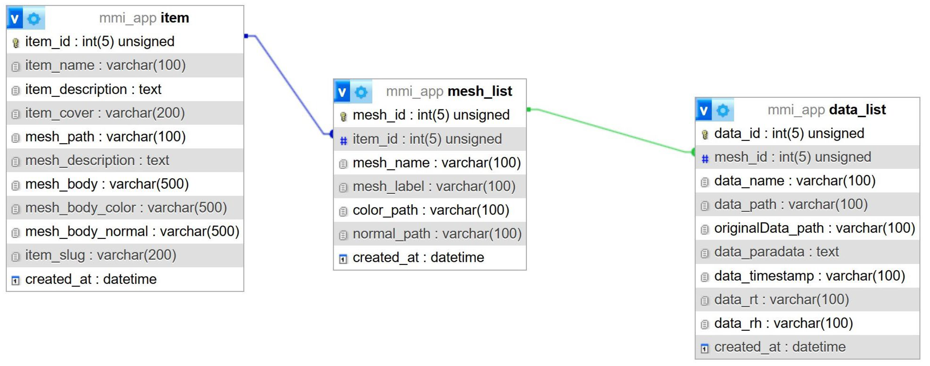
For the purposes of this web application prototype, a simple, straightforward database structure was designed to store data about a cultural heritage asset (an entity called an item in the database) digitized in 3D and investigated with multiple imaging sensors. To accomplish the objectives stated in previous sections, the database should store data about each of the item’s 3D parts (in an entity called the mesh_list) and, for each of these parts, store data about all imaging information available (in an entity called the data_list). This is a simple design with one-to-many-type relationships between the item and the mesh_list and the mesh_list and the data_list.
The entity’s structure (
Figure 1) reflects the prototype concept. The item stores metadata for the cultural heritage asset (a Text-type field for a general description), the path to the 3D model file (stored on disk), and paradata information for the 3D model (also a Text-type field for a general description). Also stored in this table are the paths for the 3D model section (if it exists) that has no imaging data attached, a section considered the mesh_body. For each of the other model sections with imaging or other associated data, the table mesh_list stores the following basic information: the internal mesh name of the section, the label to be displayed in the UI, and the paths to the colour and normal map textures. The imaging data information is stored in a simple manner: paths to the adapted texture from the imaging data and to the original image with all of the scales and other related information, paradata (as a generic Text-type description), recording time stamp, and another two fields for relative humidity and relative temperature in the proximity of the related cultural heritage asset section at the moment of the recording.
As mentioned, this is a simple structure for this stage of the development.
The database structure was created using migrations and seeds from the CodeIgniter4 MVC framework so that it can be re-built and replicated for any other DBMS. The chosen database system for this project was MySQL, a popular DBMS for web applications due to its ease of use, scalability, and reliability. The MVC framework, however, makes this web application versatile in regard to the database system used due to its Query Builder class. The main feature of this class is that the query syntax is generated by each database adapter, allowing safer queries (data retrieval, insert, and update) with minimal scripting.
Data input, display, and update actions all benefit from the MVC architecture. In this pattern, the Model represents the data and database interactions. The Model can represent a database table or a query for data input or updates. The Controller receives feedback from the user with new data to be inserted or to be displayed. In the first case, the data sent by the user are sent to the Model to be inserted into the database. In the second case, the data requested by the user are retrieved from the Model and sent to the View to be displayed.
2.3. WebGL Integration
The main feature of this web application is the custom 3D viewer, which provides an immersive and interactive experience for users. This viewer is a defined area within the user interface where all 3D and imaging information is displayed. Users can engage with the 3D scene through a range of intuitive controls, enabling actions such as rotation, panning, and zooming to examine the 3D model. Additionally, users can select which imaging data are displayed in specific sections of the 3D model. This interactive and dynamic environment is achieved with the Three.js library, which is compatible with both WebGL 1.0 and WebGL 2.0.
A key advantage of this 3D viewer is its cross-platform compatibility. It seamlessly runs on a variety of devices, including PCs, Macs, iOS, and Android devices, and it is fully accessible through mainstream web browsers. This versatility ensures that users can access and interact with 3D models and rasterized imaging data from virtually anywhere.
The 3D environment created with Three.js is based on the principles of the PBR (Physically Based Rendering) workflow. This means that texture materials and lighting in the scene are designed to mimic real-world physical properties, resulting in a high level of visual realism and accuracy. This not only enhances the visual quality of the 3D models but also provides a more lifelike representation of the imaging data.
Another notable feature of this viewer is its real-time data update capability. Users view seamless updates of the data displayed in the 3D scene. This feature is made possible through simple and efficient APIs, allowing for the dynamic visualization of information.
Furthermore, the 3D viewer offers an automated camera-positioning feature that enhances the user experience. When focusing on a specific part of a 3D model, the camera smoothly adjusts its position to provide an optimal view. This feature, powered by GSAP animations, ensures that users can effortlessly explore and inspect various elements of the 3D scene.
2.4. Front-End Design
The user interface follows the same principle of simplicity. The minimal website structure has a few static pages (Home, About, and Contact), two dynamic pages (Projects and Project View), and a management page to add a new project or update an existing one. The graphic design is realized with a Milligram cascade stylesheet and JavaScript codes for real-time display and interaction with the back end and the 3D viewer and other custom scripts, like image lightbox and others, for added functionality. The main part is the Project View page. The code is embedded in an HTML template and utilizes PHP to dynamically populate data and handle user interactions. The PHP section of the page fetches data from the database for the selected project and stores it in different variables. The HTML is simple and based on the Milligram grid.
The main section of the Project View page (
Figure 2) is split into three columns for data display. The left column is populated with two sets of radio buttons. The first set is a list with the 3D model parts loaded from the database. The second radio button set is a list with all of the recorded imaging methods for the selected 3D model part in the first list. Two more options are added by default, Default Colour and Matcap, which are not dependent on the imaging set. The middle column contains the canvas element, which is used by the 3D viewer script to display the 3D and associated imaging data. The third column has two sections: one for the original imaging data and the second for other information stored in the database for the selected imaging method. The imaging data section (top right in
Figure 2) displays the original image with all of its features (scale, axis, explanations, etc.) from which the imaging texture mapped on the 3D model was extracted. Below the main section, two additional fields contain a description of the selected project and the paradata and other descriptions for the 3D model.
2.5. Further Development
After this first phase of development, a survey of potential beneficiaries and users will be able to highlight missing features and nice-to-have options. There are a set of future developments that are scheduled to be implemented in the next instalments and that are briefly described in the following, but users’ feedback will be essential in the design of the first production version.
In terms of the database design, the current version has a minimal structure, only to include the strictly necessary data. In the final production, the database will be designed to manage collections and relationships between objects and buildings or archaeological sites. Metadata and paradata will furthermore align with current practices in the documentation and archival of cultural heritage assets.
More data to be displayed will require significant UI improvements. A future instalment based on a laborious database will make use of other frameworks like React to ease the complexity of the development process but also to accommodate new functionalities of the 3D viewer.
The technology behind the online 3D viewer allows a wide range of possibilities to take advantage of. An adjustable scale can be introduced in the viewport as an overlay that adapts to changes in the camera position in the scene in relation to the subject. Interactive tools like two-point distance measurement, profile section, or raking light, similar to 3D Hop [
28] or segment surface profiler, will greatly improve the usability of the 3D viewer. Certainly, the upload and project creation/editing section could benefit from a 3D scene editor, where the user can adjust the presentation starting position of the 3D digitized subject as well as other scene elements, like environmental light or background. But the most important improvements will be the implementation of an annotation system and a way to monitor increased-condensation-risk areas or automatically detect water infiltration.
3. Results
This section describes a case study that can serve as a demonstration of data preparation and the workflow of using the web platform. The chosen asset is an important church in Romania. The church Saint Trinity is a historical monument located in the village of Golești, belonging to the town of Ștefănești, Argeș County, Romania. It is an architectural masterpiece built in the 17th century by the master Stoica at the request of Stroe Leurdeanu, a great treasurer, and his wife, Visa. The church is a fine blend of Wallachian, Moldavian, Armenian, and Middle Eastern influences. The church has a rectangular plan with a polygonal apse, without a porch. The interior is structured into a narthex, nave, and altar. The separation of the nave from the narthex by a solid wall pierced only by a door and the four buttresses that rise to the full height of the facades are elements that differentiate the monument from other contemporary churches. The wooden polychrome iconostasis (temple) stands out for its religious depictions and extensive decorative registers dominated by phytomorphic elements. The imperial doors and the bishop’s throne are carved in the Brâncovenesc style. The stone portal from the entrance to the nave bears the inscription of its founders, Stroe and Visa. The church is part of an ensemble of historical monuments located in the territory of Golești village belonging to Ștefănești town. It is classified as a historical monument under code LMI AG-II-a-A-13698.
3.1. Data Acquisition
For this project demonstration, the data acquisition plan included the 3D digitization of the church’s exterior walls and roof, thermal imaging with different sensors and at different epochs, and UV imaging for a selected area.
3.1.1. Three-Dimensional Digitization of the Church
The digitization of the exterior of the church was based on photogrammetric measurements and was carried out using a UAS, model DJI M30T, produced by SZ DJI Technology Co., Ltd (Shenzhen, Guangdong, China). It features three cameras that shoot at the same time: a wide camera (12 megapixels), a zoom camera (48 megapixels), and a thermal camera (640 × 512 pixels). There are a couple of high trees on the church’s west side, where the entrance portal is located, as well as on the north narthex wall (see the red-marked area in
Figure 3), making it impossible to access with the UAS. For this reason, these sectors were digitized using a Sony A7R3 camera (42 megapixels) from the ground level, with a monopod for higher perspectives. For alignment purposes and scale, both image sets included 12 ground control points (coded targets) around the church, with the precise distance measured between them. In total, 1556 images from the wide camera were used for aerial photogrammetry processing, along with 1114 images for the ground level. To have a uniform visual aspect in both image sets, a colour calibration chart and a white balance chart were also used.
Both image sets were processed in Agisoft Metashape PRO v2.0 at the ultra-high-quality setting. For the aerial image set, with a 12-megapixel wide camera (see
Figure 4), the final mesh amounted to 134 million polygons, while the ground image set had a sum of 113 million polygons. As part of the optimization process, two models were exported from each image set processed in Wavefront OBJ file format: a high-poly mesh (10 million polygons) and a low-poly mesh (500,000 polygons). The low-poly meshes will be the base models for the following data preparation stage, so they also had high-resolution textures (8192 × 8192 pixels) exported as well.
3.1.2. Thermal Imaging
Thermal imaging is a widely used non-invasive method to map the infrared radiation that a surface emits [
29,
30]. It is mainly used in search-and-rescue missions with UAS systems and for buildings’ energy efficiency evaluations in real estate and civil engineering. In the built cultural heritage field, thermal imaging is relevant for the assessment of the state of conservation. One of the main features of this method is being able to view, in real time, the different behaviours of construction materials, water infiltration [
31,
32,
33], cracks [
34], or detachments in built structures [
35].
Thermal imaging can refer to two types of recordings: qualitative (distribution of the estimated radiation intensity over the surface) and quantitative (distribution of the real temperature of the surface with compensation for other factors that affect the measurements). For the accurate measurement of the temperature of the surface, apparent temperature, emissivity, ambient temperature, relative humidity, and surface features must be taken into account. The sensor plane of the camera must be parallel with the recorded surface at a known distance. An important aspect of outdoor quantitative measurements carried out with thermal cameras is that they must be carried out before sunrise or after sunset because the Sun’s radiation and sky reflections greatly impact the accuracy of the measurements. Other reported systems, like that in [
36], are able to perform both 3D and IR scanning regardless of the lighting conditions.
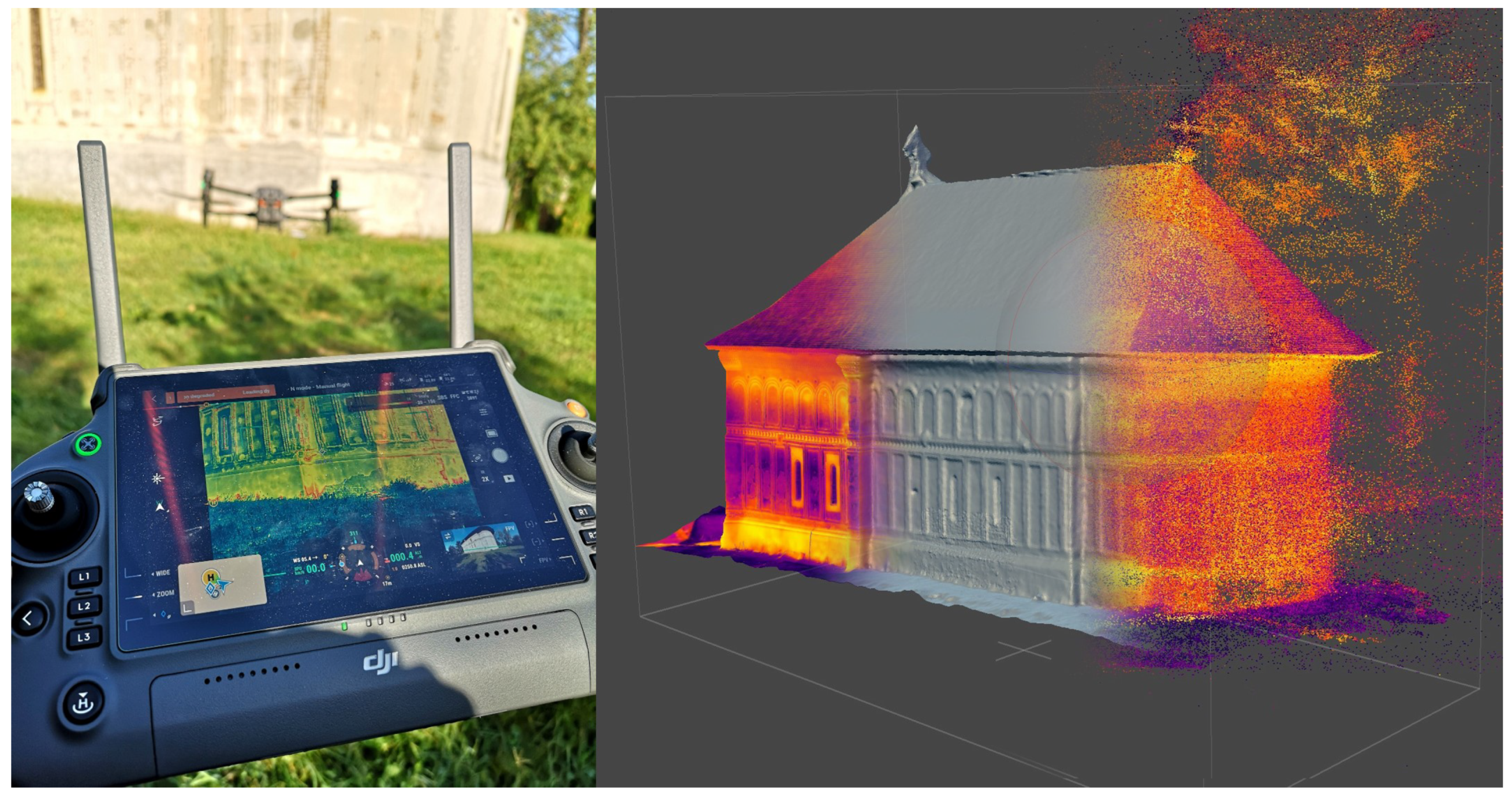
Two IR imaging systems were employed. The UAS DJI M30T used for aerial photogrammetry already has its own integrated thermal camera that records thermograms at the same time as photo images. The thermal camera has an equivalent focal length of 40 mm, 640 × 512 pixels, and a measurement accuracy of ±2 °C. The images were saved and then processed directly in Agisoft Metashape PRO v2.0, an approach similar to that in [
37]. This image set was processed directly without any prior adjustments in other software. The purpose in this case was not to obtain a usable 3D model but to generate textures that can later be baked for the accurate 3D model generated from the photo image set. Even so, with the 3D mesh generated with the medium-quality factor in Metashape, the result was better than expected (
Figure 5, right, middle section), considering that thermal images retain far fewer details about the surface than photographic images.
The second IR imaging system employed was a state-of-the-art FLIR T1020 camera, produced by Teledyne FLIR LLC, USA. It features a 120° FOV lens and 1024 × 768 pixel resolution, with very good image stabilization. The thermal sensitivity of this system is less than 20 mK at 30 °C.
With this system, two image sets were recorded: one after sunset and another in the morning. The set acquired in the morning was after sunrise, so the data are not quite reliable considering the errors induced by direct Sun exposure and other environmental reflections. These data were not included in the project. All images were recorded at the same distance from the church exterior walls, which was 5 m (see
Figure 6). The high image stabilization of the camera allowed the images to be recorded handheld. For each position, the images were shot from two height levels: one for the lower part of the wall, below the horizontal decorative band that splits two vertical registers, and the other one above it to maintain a parallel orientation of the camera sensor to the wall. The camera was set on Auto mode (emissivity: 0.95; reflected temperature: 16.0 °C), but the parameters can be adjusted afterwards for corrections in the FLIR Thermal Studio Suite v.1.9.95 software. The optical focus was adjusted manually for each image to ensure the best detail quality.
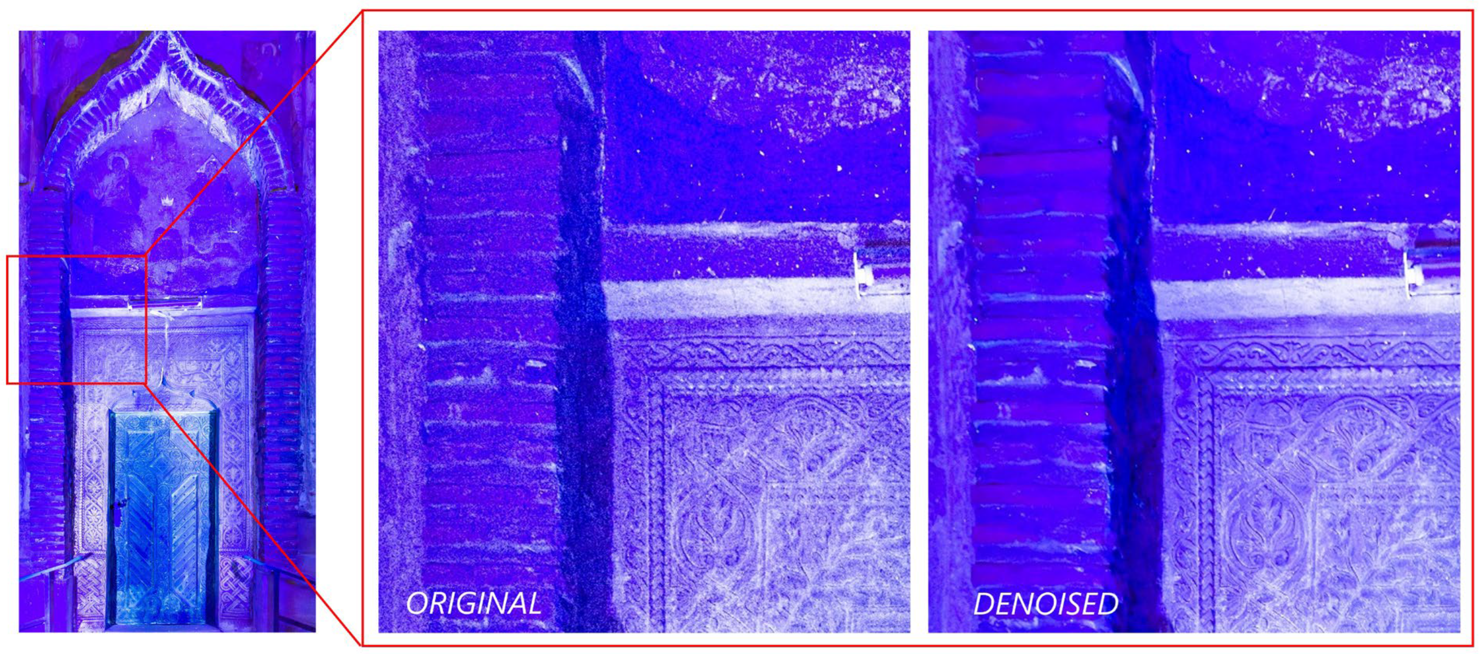
3.1.3. Ultraviolet Fluorescence Imaging
The west wall of the church features a portal with a painted scene above the entrance. A pair of UV lamps from Karl Deutsch (Wuppertal, Germany) were used to highlight possible areas of interest with UV fluorescence. These lamps have a maximum peak at 365 nm and 60 W/m
2 intensity at 0,4 m distance. The UV fluorescence manifests in the visible band of the electromagnetic spectrum, so it was recorded with a Sony A7R3 (Tokyo, Japan) during the night in RAW format. The images were processed in Adobe Lightroom 2023 Classic v13, and the Denoising AI algorithm available in the program was also used for experimental purposes to enhance the quality of the images without altering the details, colours, or content (see
Figure 7). But, as with any imaging filter, special attention must be given so that no details are lost.
3.2. Data Preparation
Like with any H-BIM solution, there is no automated way to drag and drop data or an ‘algorithm’ to optimize, reference, and make the project look good and easy to follow. In regard to visual presentation, the difference between scan-to-BIM solutions and the presented concept is that this solution uses optimized 3D scanned models instead of modelled replicas (as BIM solutions usually employ). For this reason, the 3D digitization and optimization process must be professionally carried out. For the data to be presented with a high level of realism, it is necessary to record and retain as many details as possible with the correct colours.
This section will describe all of the steps from the processed 3D and imaging data to the ready-to-publish online content.
3.2.1. Preparation of 3D Data
As mentioned, for online use, 3D digitized data must be optimized. The methodology employed for this project is structured in several steps. The first step was already described, where the generated raw 3D model is simplified in two versions: one with 10 million polygons, retaining all of the detailed geometry, and one with 500,000 polygons that loosely retains the geometrical features.
The second step is to split the low-poly mesh into the parts (or sections) of interest. These parts of the general model are selected to highlight certain building elements or to correspond to the investigated multimodal imaging areas. Blender 3.6.5 LTS was used for this stage. Photogrammetric processing for the 3D surface of the church resulted in two 3D mesh models (one for aerial photogrammetry and the other one for terrestrial photogrammetry), with each mesh model being exported in two versions: high and low poly. In Blender, these meshes had to be re-oriented (repositioned and rotated) so that the final exported scene for online use would be correctly displayed. The colour texture and normal map baking processes require the source mesh (high poly) and the optimized mesh (low poly) to have the exact same position for a correct bake. For this reason, the low- and high-poly meshes had to be aligned at the same time. This process is performed manually. After this alignment, the low-poly meshes were duplicated. The default colour textures of the duplicates were deleted, as they are going to be baked based on new UV (not to be confused with the acronym for ultraviolet) coordinate maps generated further in the process.
Then, the low-poly models were cleaned and cut to resemble the complete shape of the church 3D model. Now, these unified models can be split into the sections of interest (see
Figure 8).
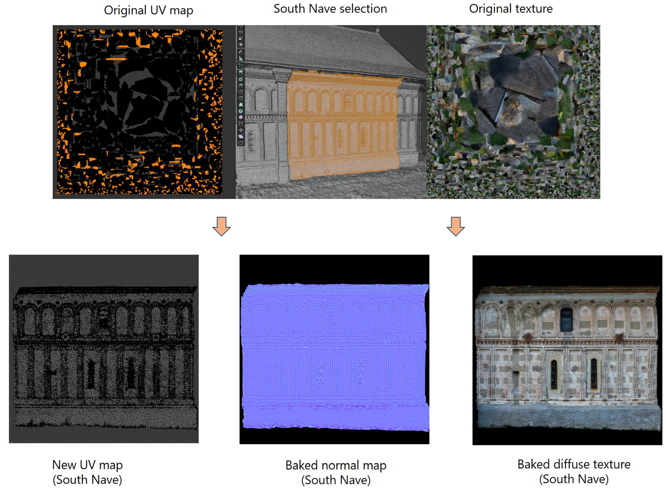
For each church section, the UV coordinate map was regenerated (a process known as retopology) for easier referencing of other imaging data, and a new texture was created. In this case, where all the parts are planar, the easiest method to generate a UV coordinate map that best resembles the topology of the walls was the Project from View unwrapping method, provided that the view was adjusted to be perpendicular to the wall part, and the viewport camera was set to orthographic.
With the new UV coordinate maps, the colour information is baked from the original low-poly mesh into the new textures of the duplicates and saved as separate image files. The baking method used was Blender Cycles’ rendering engine’s own baking feature with the Selected to Active feature turned on (meaning the colour from the selected mesh was baked into the active one—the duplicate).
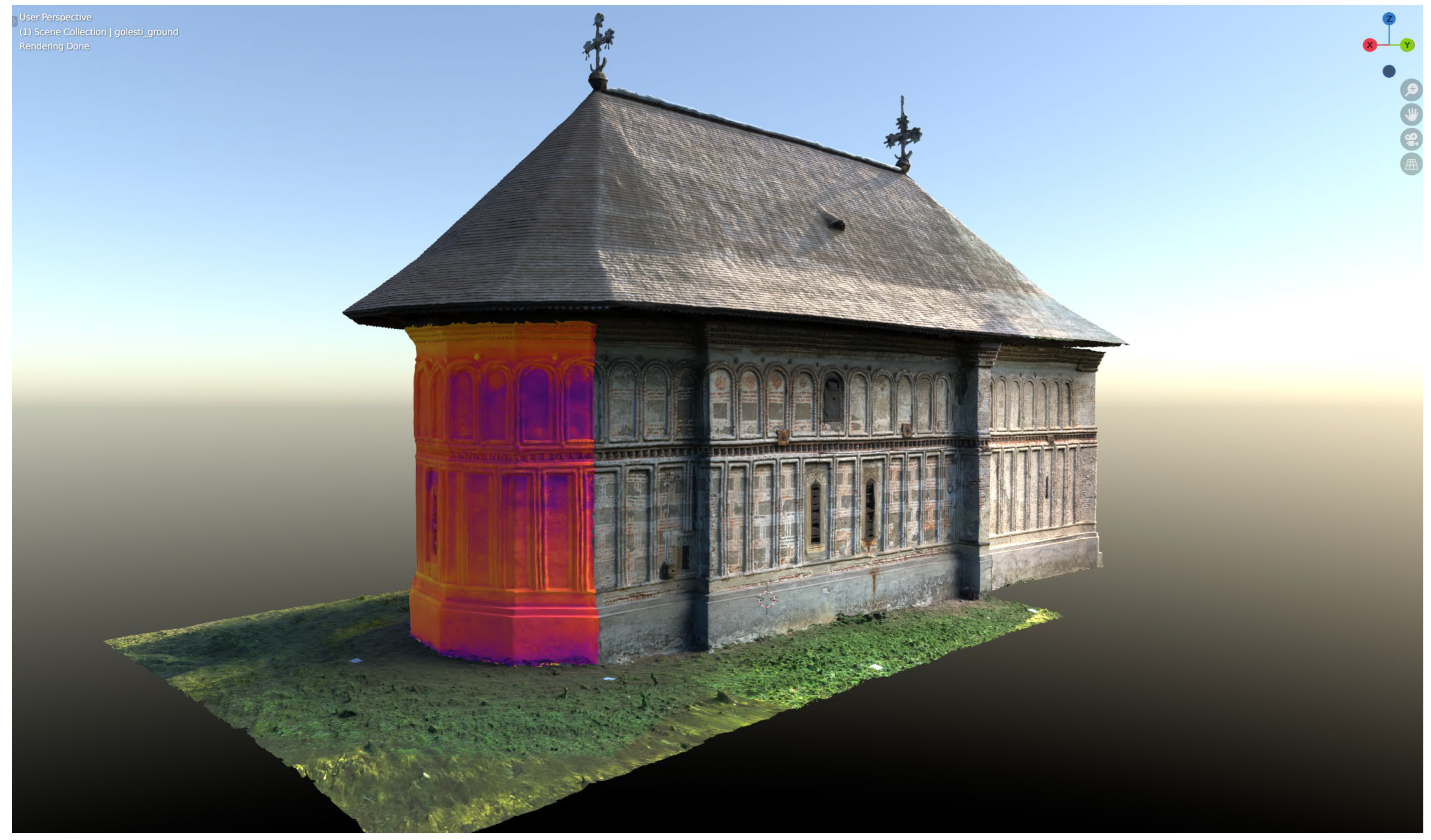
Figure 9 shows the distribution of the polygons representing the south nave wall selection (shown in orange) in the original UV coordinate map as it was generated by Metashape, as well as the original texture for the whole church. In the same figure, the new regenerated UV coordinate map of the south nave wall is shown after it was separated from the main mesh. The baked colour texture with the new UV coordinates is now helpful in referencing other imaging data.
The third step is to recover all of the geometrical details for the low-poly mesh from the high-poly one. This can be carried out using many methods. The most efficient method from our point of view is the use of Adobe Substance 3D Painter 2022 v 8.3.1 (Steam Edition) by baking the normal maps from the high-poly mesh and exporting them as textures. First, the 3D models with the new UV coordinate maps and orientation (due to the alignment) are exported together with their high-poly pairs. In Substance 3D Painter, the low-poly model is imported, and, on the baking screen, normal maps are generated based on the corresponding high-poly model. The mesh maps generated are exported as image files (in this case, PNG file format) for each 3D model section.
The resulting normal map textures are imported into Blender and assigned to each mesh section. The process is now complete, and the 3D model can be exported as a single file by selecting all of the component parts. The chosen file format was Autodesk FBX for its good compression and portability. Each mesh part is renamed with meaningful titles so it will be easy to recognize when imported into the web platform.
3.2.2. Imaging Data Preparation
In this case study, there are two situations: the thermal texture resulting from the aerial thermal photogrammetry processing and the image sets resulting from the ground sensors (thermal and UV fluorescence).
For aerial thermal imaging, the easiest solution was to export the resulting photogrammetric 3D model and its colour texture (colour being the thermal information) and import them into the Blender scene of the complete church 3D model split into sections. After carefully aligning the ‘thermal 3D model’ with the complete church, the thermal texture could be baked for each of the church sections (
Figure 10) as new textures. This set was available only for the areas that were recorded with the UAS, so the west side and the south narthex are not covered.
For the ground sensors (thermal and UV fluorescence data), considering the complexity of all possible case studies, it was decided that the best way to reference any imaging data to the 3D surface is manually. Any automated solution required too many control parameters and manual verifications, which defeated the purpose of saving time. The reconstructed UV coordinate maps simplified this process. By using any image-editing software, in this case, Adobe Photoshop 2024 v25.1, the imaging data can be superimposed over the texture of the corresponding section. The new texture has the same size and format as the original texture and is transparent in the areas where the imaging data do not cover the surface. Most areas were recorded from different positions, so the final texture would be a mosaic from all corresponding images.
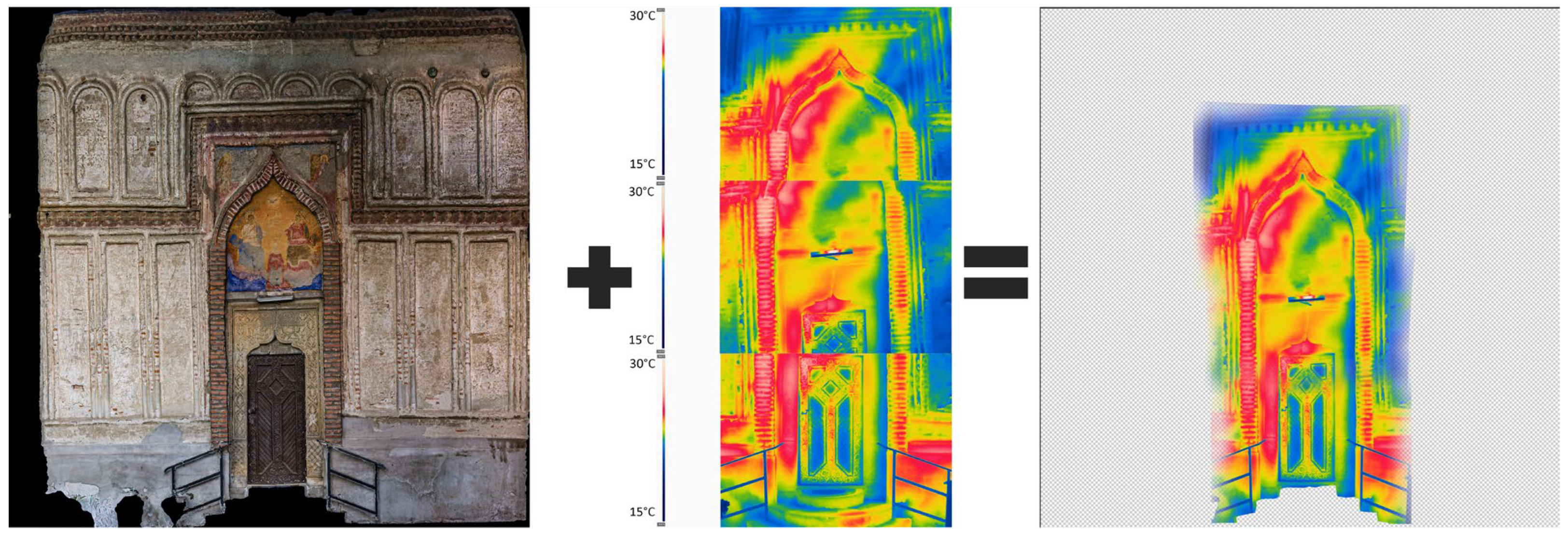
Figure 11 presents the final texture, generated from three different thermal images, with an Overlay mode that emphasizes the surface features from the underlying colour texture.
3.3. Web Application Data Input and Visualization
In the web application, the data upload was intended to be as simple as possible. Using intuitive forms, the user creates a new project by uploading the 3D model and all of the required information. The model is then analysed, and a list of component mesh parts is displayed with their names. The user can choose which parts will be relevant for adding imaging data and add relevant information for each of them. Adding new imaging data for each part will cause a new pop-up card to appear with a new form to complete. When all of the required information is inputted, the project is saved, and all of the data are stored on the disk and in the database.
To view a project in the platform user interface, it must be selected from the project list. The project list is populated from the database. When a project is selected, a dedicated page is generated from the information stored in the database for this project (see
Figure 2). There are several main sections where the information is displayed: title section, model parts, method list, 3D canvas, imaging data section, additional information section, and two more descriptive sections for project details and 3D digitization paradata.
The model parts section lists all of the recorded 3D model elements in the database. They are displayed as radio button lists. When selecting one of the parts, the method list section is updated with the list of the imaging data available for that specific element of the 3D model. At the same time, the 3D viewer loaded in the 3D canvas section automatically changes the camera position to focus on the selected 3D element.
As part of the future development plan, this selection will also be available directly on the 3D model. The user can rotate, pan, or zoom in and out in the 3D viewer using the mouse controls. When selecting one of the imaging methods in the method list, the respective imaging data are loaded on the surface of the 3D element in the viewer, allowing the user to further explore the 3D scene. In the imaging data section is displayed the original imaging data used for the mapping of the 3D element. It can be clicked to be enlarged in a lightbox element. The additional data section displays the imaging paradata and other related information.
4. Discussion
This iteration of the web application serves as a proof of concept for a dedicated web platform designed to manage and disseminate 3D digitized and multimodal imaging data for a wide range of cultural heritage assets, including buildings and museum collection items. It revolves around the concept of an H-BIM and digital twins for historical structures and cultural artefacts, with a particular emphasis on the utilization and enhancement of 3D scanned data. As elaborated in this paper, the current version has limited features, but it effectively showcases the capabilities of the underlying technologies.
Section 2.5 provides a brief overview of forthcoming updates.
While the concept is based on a minimal but versatile web application, it relies on a well-planned data collection strategy. All of the subject areas of interest must be defined beforehand so that 3D digitization and multimodal imaging data can be correctly recorded and referenced.
Figure 12 depicts the flow of data from the moment of recording to the registration in the web application database and server disk. This workflow stems from the realism requirement of the concept. Data should be presented in the online interactive environment and retain as much of the geometrical details of the original 3D scan. The proposed steps successfully lead to such an achievement, the main condition being the quality of the original scan. The free Blender software plays a central role in this workflow. Here, the first action within Blender is to import, duplicate (for baking purposes), and align all of the subject’s digitized sources into a single object. Then, the object is split into the parts of interest, and new UV coordinate maps are generated for each of the resulting sections. After this step, the colour texture coordinates will no longer match with the 3D surface, so it needs to be baked later from the duplicate mesh.
The final object is repositioned in the scene, losing its initial coordinates. For this reason, the workflow requires, in this initial stage, both low-poly and high-poly meshes so that they keep the same 3D coordinates during alignment and repositioning. When exported to another software—Substance 3D Painter—to generate the normal maps, the low-poly and high-poly meshes must have the same position for a correct geometry mapping. Normal map baking will generate a texture for each separate part of the object and will export them as separate files. Back in Blender, the normal maps can be imported to check the details directly on the low-poly mesh. At this point, the colour texture for each part can be baked as well and saved to the disk.
In this case, there was another photogrammetric 3D model resulting from the aerial thermal images. The purpose of this model was just to use its texture to create a set of thermal textures for each part of the main model. The thermal mesh is imported into the same scene in Blender and aligned to the position of the main model, and then, for each part, a new texture is baked and saved to the disk.
For the other imaging systems, the simplest method to create textures is to overlap them with the colour texture of the designated part in any image-editing software. In a similar manner, any other type of information that can be mapped on a surface can be included: spectral data, drawings, old photographs, etc. As an observation, photogrammetry-based data were much easier to map on 3D textures.
The web application database stores the paths to the 3D model and its files, as well as other important information, like metadata and paradata. The presented form is not suitable for complex-scale projects, only for simple case studies like the one described in
Section 3, where only the conservation state assessment of the external walls was needed. As this project is still in progress, a future iteration will consider beneficiary and public feedback along with the proposed development roadmap.
For the presented case study, 1556 images were used for aerial photogrammetry, 1555 images were used for aerial thermography and photogrammetry, 1114 images were used for terrestrial photogrammetry, and 34 images were used for ground-level thermography and several UV fluorescence images during the night. These image sets resulted in a 3D model in FBX file format of 43 MB, with 11 4K colour textures for the mesh parts (summing up to 41 MB) and 11 4K normal map textures (summing up to 103 MB). For imaging data, 15 texture files were generated and processed from the three sensors involved (summing up to 108 MB). A total of 296 MB of data were used for the whole case study. These numbers can be optimized, but even so, this is a reasonable data weight for online usage.


