Article

Interferometric Quantification of the Impact of Relative Humidity Variations on Cultural Heritage

Institute of Electronic Structure and Laser, Foundation for Research and Technology Hellas, N Plastira 100, 11703 Herakleion, Greece
Heritage 2023, 6(1), 177-198; https://doi.org/10.3390/heritage6010009
Submission received: 26 October 2022 / Revised: 12 December 2022 / Accepted: 15 December 2022 / Published: 23 December 2022

Abstract

:
It has been shown that Relative Humidity (RH) provokes dimensional displacement detectable directly from surfaces using holographic interferometry. RH variations constitute a physical environmental load that drives organic materials to a constant equilibrium cycle. This paper is a small synopsis of the interferometric research direction and a data acquisition on the detection of the dimensional impact of relative humidity on cultural heritage objects. Since RH cycling is unavoidable, the interferometric data change depends on the object structure and RH cycle characteristics. Based on the fact that each artwork is by construction unique, and on the observation that the effects of an RH cycle on the structural condition of any artwork are also unique but the preventive conservation strategies require generalised approaches and not on a case-by-case study, being introduced is a novel, universal, preventive deterioration methodology: “deformation threshold value” (DTV). DTV is assignable to each distinct object in order to control routinely its structural condition and prevent damage. DTV is not assigned hypothetically based on any assumed/expected reactions but from a monitored calibration of the artwork in its environment. Each artwork in its hosted environment has its unique reaction. The reaction, though, is not steady but changes as the artwork changes. DTV can be acquired routinely and valued accordingly to seasonal RH change. Monitoring the seasonal RH and seasonal dimensional reaction has been shown to correspond to a standard DTV pattern whose deviations violate the expected seasonal reaction. Through the interferometric monitoring of surface, the distinct DTV acts as a safeguard for the artwork. In this synopsis, some results of the generation of DTVs are shown. Our future plan is for the DTV numbers to serve as data inputs for preventive models to formulate a distinct risk index representative of each artwork condition and to be used as remote risk warning to prevent its deterioration. Based on the DTV concept, methods and instruments for sequential data acquisition aim to present experimental data outputs as DTVs that identify transient shape changes prior to visible damage have been developed. In this research, the starting point was the interferometric quantification of the displacement of well-characterized fresh samples. The fresh samples are known in terms of density, cut, thickness, moisture content, structural condition and are submitted to RH simulation cycles. Shown here are three exemplary cases: usual, abrupt and smooth. The interferometric monitoring following the cycles of RH is a long-term duration of several weeks; measurements are performed directly from the surface, and relative displacement (RD) from temporal measurements of interference fringes provide the required output data to calculate the rate of displacement (RoD) of the surface. Measuring the impact of RH directly from the artwork surface allows the detection of the temporal diversity of structural reactions to the same RH cycle for distinct artworks. The monitoring system uses interferometric precision provided by digital holographic speckle-pattern interferometry (DHSPI) placed on a specially designed climate chamber DHSPI monitoring workstation.

1. Introduction

This paper is written to highlight the importance of experimental data directly from surfaces to the potential universal concept of deformation threshold value of each distinct artwork acting as preventive risk index throughout its lifetime.
The paper provides quantifiable interferometric examples from direct monitoring of surface reactions under simulated environmental cycles of RH. The experimental data allow the classification of the roles of different structural parameters, e.g., thickness, proving ability to typify the susceptibility to RH changes and dry-wet cycles for distinct objects. Experimental data are critical for standardising the future milestones of development in terms of software for the automated evaluation of DTVs. A mathematical model able to foresee—not forecast—ageing, would be possible from experimental data gathered from monitoring the full cycle from elasticity to fracture implementing an even longer-term DTV, but at the moment this remains ambitious future work.
Selected experimental data from the usual, abrupt and smooth RH values briefly reported here are taken from experiments on: (a) the fast, immediate reactions occurring on material surfaces upon abrupt- or smooth-induced rate of change (ΔRH) validating the sensitivity of organic materials to environmental RH; (b) the DTV classification from repetitive cycles depending on the diverse densities and thicknesses validating the clear ability of technique and method to typify and generalise distinct reactions; (c) the association of ΔRH change and rate of displacement to physical properties as the mass change shows hysteresis in the dynamic sorption isotherm and a greater rate of displacement during drying.
Short- and long-term experiments were performed to identify signs of ageing of the samples under RH cycling are summarised. The ΔRH effects in the evolution of the mass and the rate of displacement are graphically represented from dense experimental data. An offset in values with interesting behaviour was observed, highlighting the ageing of wood. The long-term cycles finally showed displacement variability, explained as internal damage evolution. Evidence of new defects suggest the onset of fracture. It is necessary to develop mathematical models from the experimental data, which require longer durations to be achieved and has not yet been accomplished in our experiments.
In general, interferometry-captured reactions can provide the essential experimental data to produce a future preventive damage model for distinct art objects. The experimental data direct from surfaces can be used to determine a distinct damage deformation threshold of each artwork of concern, after which a new characteristic condition of reactions is established, or damage occurs. The experimental data direct from surfaces, once started and routinely monitored, can allow us to define the distinct time at which point of elasticity curve the artwork is found. The process can be performed for each material or artist construction under specific conditioning cycles.
In this context, the study from fresh samples to fracture is still in progress. The experiment is performed on organic samples bearing a variable wood density and thickness under short-, long- and far-seeing-term RH cycles, and monitoring until the samples show visible signs of displacement variability, signifying the start of irreversible damage.
The important potential of the DHSPI monitoring method to get experimental data from ageing-damaging processes to feed and verify theoretical assumptions is enormous for conservation community. Nevertheless, many more long-term experiments are needed to simulate any combination of environmental conditions found in the literature, with any desirable material and impact monitored in full cycles. Such validation of safety values will provide large data numbers of possible surface spatial positions which are required to derive safe ranges and DTVs for precious artworks.
The deformation threshold value can act as a warning signal in a risk-index classification to allow for routine monitoring and mature technology for preventive deterioration assessments on the museum floor. The technology and methodology are available, and this is confirmed in this paper.

1.1. Preventive Conservation

It is known that works of art constantly undergo changes in their condition due to environmental impact. The effort to optimize instrumentation and diagnostic methods to enrich everyday practices, upgrade skills and safeguard artworks holds a constant challenge for professionals involved in artwork preventive maintenance. Handling, transportation, conservation treatments, exposure to environmental fluctuations and recently climate change can all take their toll in structural deterioration. Painted artworks, especially multilayered, mixed-material painted artworks, can be described in terms of non-homogeneous anisotropic engineering structures with non-typical engineering characteristics of being monolayer or single-material. These are complex constructions with a variety of materials in a mixed compilation of layers, and, for such constructions, the main reason for structural alterations leading to damage is mostly the multilayered anisotropic displacement of the multiple constituents with diverse elasticity properties and thermal coefficients causing different dimensional changes in the different layers.
Fluctuations of RH provokes the expansion and contraction of wood elements and, as such, differentiation in dimensional displacement can lead to irreversible damage [1,2,3,4,5,6]. The material cycles of moisture adsorption and desorption is the dominant process and is dependent on the ambient RH for a material to maintain equilibrium with its environment; it is a critical process influencing physicochemical, mechanical and structural alterations [4,5,6,7,8,9]. Organic materials based on carbon and hydrogen molecules are porous and characterized as hydrophilic. When the pores are of the order of thousands of a mm, as in the case of wood and cellulose, they have a large internal surface area, allowing significant water absorption and moisture transmission. As water vapour molecules in the air are adsorbed to the internal surfaces the water content increases, provoking structural expansion [8,9,10]. In particular, wood is a frequently used material and plays a dominant role in cultural heritage (CH), given that many art objects—from panel paintings and wood icons to wood furniture and wood statues—are composed to a large extent of wood, wood deterioration has become a thoroughly studied subject [9,10,11,12,13,14,15,16,17,18]. Additionally, in the last three decades, concern for the safe maintenance of tangible and intangible CH has been augmented due to worries for climate impact and phenomena closely related to climate change, and extreme events with vast consequence to CH safety [19,20]. Climate change’s possible effects on CH have been investigated through large European projects lasting many years, and it is widely accepted that the climate affects the cycle phenomena in environmental alterations, accelerating deterioration. At present, direct measurement solutions and preventive measures are an immense priority [21,22,23,24].

1.2. Coherent Interferometry: Direct Surface Monitoring for Distinct Data Aqcuisition

Coherent techniques, based on interferometry superimposed principle getting structural information directly from surfaces, have been successfully introduced into CH.
The evidence that any change in RH values impacts the artwork, provoking a fast dimensional displacement measurable by direct coherent light reflected on its surface, has been shown in a number of experiments with digital holographic speckle pattern interferometry (DHSPI), in which various samples have been sequentially monitored for their structural responses to environmental alterations [24,25,26,27,28].
Another coherent technique known for its insensitivity to vibrations is the digital speckle shearography (DSS). It has been shown to serve in damage assessments since it provides a clear image of damaging impact, identifying damaging areas faster than other more sensitive interferometric techniques with denser interferometric data. Shearography was employed as an important component in a multisensor for impact identification, especially for loan artworks to be compared before and after transportation, as has been studied within the European Commission (EC) project Multi-Encode [29,30,31,32,33,34,35]. In an effort to further detail the damage assessment of shearography, it has also been shown that photorefractive (PRC) interferometry can provide the highest interferometrically available information density content within strict, boundaried laboratory conditions. PRC results can be very crucial in the identification of tiny unique features in artworks, enabling unique antifraud protocols to take place, as has been validated at European project Multiencode (https://cordis.europa.eu/project/id/6427, accessed on 15 October 2022), although it has been proved to be highly sensitive for out-of-laboratory applications [33].
Here the DHSPI system has been implemented to gather data directly from surfaces.

1.3. State of the Art

As structural responses are primarily considered, the dimensional changes caused by a physical or artificial force provoke a displacement that changes slightly and transiently the spatial coordinates defining the artwork’s surface [34]. To measure changes of spatial coordinates as a response to environmental changes, the scale of measurement is required to be in a micrometre scale and non-destructive (ND), ensuring a safe and reversible impact [35]. The interferometric sensitivity is capable of recording negligible dimensional effects, in contrast to irreversible or damage events only [31]. The difference is crucial for artwork safety since dimensional effects with tiny alterations in spatial coordinates signify dimensional change under even controlled RH changes and represent small transient impacts onto the structure. Realistic RH values from internal conditions extracted from safe museum rooms can be simulated and the impact monitored in sequential recordings [36,37,38].
It is well-accepted that certain ranges of RH and temperature (T) variations are considered as safe limits, [2,3,4,5,6,7]. Although, within the accepted safe range, elastic recoverable deformation can occur, without induced stresses to exceed the yield point, there are little experimental data given [14,18,19,20] to assess the safe limit argument that requires repetitive full field directly from surface sequential monitoring data to be available for validation. Long-term structural deterioration is a slow process and remains invisible as long as a material maintains elastic recovery. Deformation is a product of spatial displacement from alterations which provoke slow but steady structural changes. Deformations that occur as a response to continuous alterations in RH may compromise structural integrity long before any damage occurs on a surface. The physic-mechanical outcomes of deterioration processes on surfaces are visible signs of advanced damage and fracture. Fracture at any visible level or form is an undesired effect for works of art. In this context, preventive conservation in response is a dominant aim in the conservation of historic and artistic works. The aim of long-term monitoring through cycles of RH change research based on recommendations from the European Noah’s Ark project were implemented during the European Project Climate for Culture [37].
A more direct approach is found in the use of the complete “DHSPI climate chamber workstation monitoring” and the DTV methodology to monitor the effects of RH fluctuations. It is engaged in the measurements of the displacement field of the surface, and this is represented by a number extracted from raw interference fringes at each interferogram. The fringe data are used to assign a value reading at each interferogram and it is produced in a temporal evolution in long monitoring experiments. Surface relative displacement due to RH change is captured in a remote, real-time, automated operation with pre-selected intervals according to the expected effects of ΔRH, allowing the continuous monitoring of surface displacement throughout the full cycle of RH change.
The experimental methodology and procedure are presented with some characteristic results.

1.4. Brief Look into Fundamental Theory

Holographic Interferometry

Optical holography geometry, employed in the holographic interferometry digital counterpart used in this research, allows the comparison of diffuse wavefronts from opaque arbitrary objects that cannot be interferometrically compared [39,40]. Conventional interferometry, such as Michelson, only allows simple geometrical wavefronts as spherical or plane to be compared. The surface of an artwork is illuminated at distinct positions before at rest position and after is displaced under a load. Due to the load, the surface is displaced to a new position either instantly or dynamically in sequential positions, as in the case of environmental impact.
Assuming instantaneous positions, point P(x, y) of the surface is at rest and P′(x′, y′) is after load. Light scattered by the surface in the neighbourhood of point P gives rise to a complex amplitude U0 (x, y; z) in a plane at a distance z from the object. If the corresponding irradiance I0 (x, y; z) is detected at the screen after imaging through a finite aperture Q, a noisy spot-type appearance would dominate the field (shown in insert of Figure 1). This high-contrast speckle effect is an inherent property of TEM00 lasers from the photon interference of highly coherent beams. The speckle (objective speckle) is the result of the constructive and destructive interference of neighbouring photons and is the reason lasers have a granulated texture. Speckle in the start of lasers’ invention was considered just noise, and a lot of effort was put to avoid it before the recognition that speckle could play a significant role in measurement. However, if we apply a load on the surface for a second exposure, a second optical wave scattered from the neighbourhood of P is formed. This wave is identical to the first wave but has a slight displacement travelling in a slightly different direction. At a given distance z from the object, this wave will have a complex amplitude U’0 (x,y; z) which differs in detail from U0 (x,y; z). If we could compare the corresponding speckle patterns I0 (x,y; z) and I′0 (x,y; z) at an arbitrary plane in front of the object, their detailed structures would be completely different that is, they would be completely uncorrelated.
However, there exists one certain distance z from the object at which U0 (x,y; z) and U′0 (x,y; z) will be nearly identical, except for a very small relative displacement, and, as such, a variation in phase (as seen by the red line in Figure 1) whose spatial scale is large in comparison with the variation gives rise to the speckle (black lines) which forms the visible interference fringes due to the constructive and destructive interference of highly coherent light waves. Figure 1 shows the displaced surface with light propagating twice to a screen where an intensity variation is produced by the interference of the two beams at P and P′. Irradiance distributions can be exploited and provide information. The irradiance pattern formed when the field at z distance from the object is imaged and has a fine speckle structure modulated by the broader cosinusoidal variation, which gives rise to the visible secondary fringes of holographic interferometry. The speckle pattern, consisting of random irradiance variations of relatively high spatial frequency, conveys information about the microstructure contour of the surface and the size of the viewing aperture, whereas the systematic low-frequency variation which constitutes the fringes of holographic interferometry conveys information about the displacement and surface morphology deformation of the object between exposures. The fringes of hologram interferometry appear to be localised for the given viewing direction only at distance z from the object; at other distances, only speckles will be seen. The selection of the f number, performed prior to recording, determines the z.
The phase difference δ is the variation that gives rise to the fringes of holographic interferometry and can be directly calculated to provide the phase change, due to object displacement in optical pathlengths so that the phase difference is measured in integral numbers N of the interference pairs δ = N 2π/λ. This simple equation is the basis for a simple geometric relation between object displacement and the fringe patterns and is directly quantitative, providing a number for the whole-body displacement at time instances of each recorded interferogram facilitating the direct quantitative deformation measurements in order to extract the missing experimental data [37].

2. Experimental Workstation

2.1. Implemented Optical Geometry

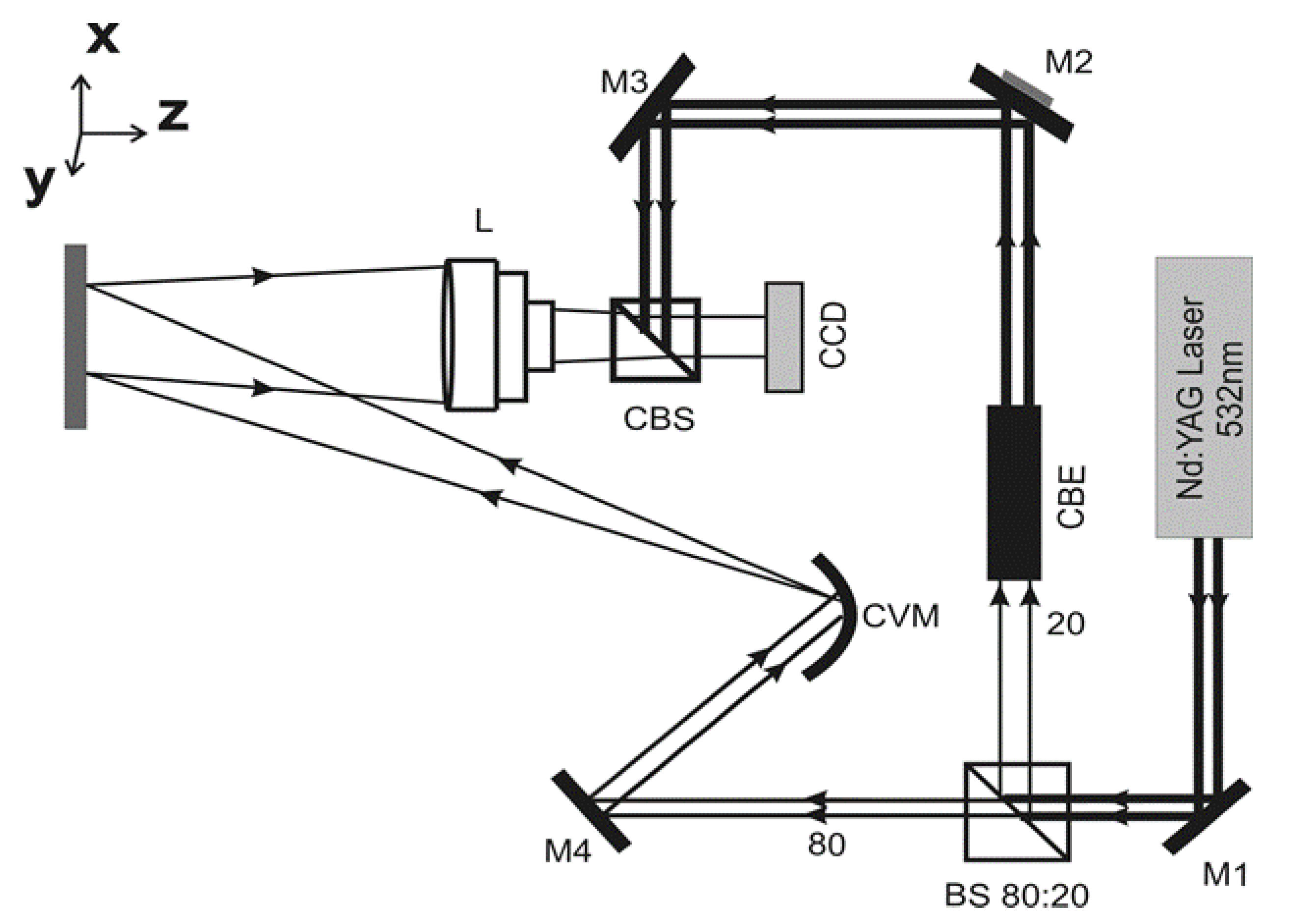
The optical geometry in the DHSPI system is designed according to the strict boundary conditions for optical off-axis transmission holography. It is coupled with a phase-shifted digital recording apparatus operation controlled through specially designed automation algorithms. The hw/sw assembly provides a sequential exposure mode of application to allow data capture from dynamic events where a potentially infinite number of inbetween positions can be covered from the displaced surface [38]. The geometry utilized in the portable instrument is shown in the scheme of Figure 2. Two beams are shown serving as (a) an object illumination beam and (b) a reference phase-shifted beam, a collecting lens driving the object beam to a beam combiner to interfere in an angle θ, with the reference and their interference product to be captured at the CCD position of the image plane. In DHSPI geometry, the displacement sensitivity vector is in z direction where dimensional changes manifests. The generated fringes are the visible, full-field contours of intensity distribution.

2.2. DHSPI Climate Chamber Workstation Monitoring

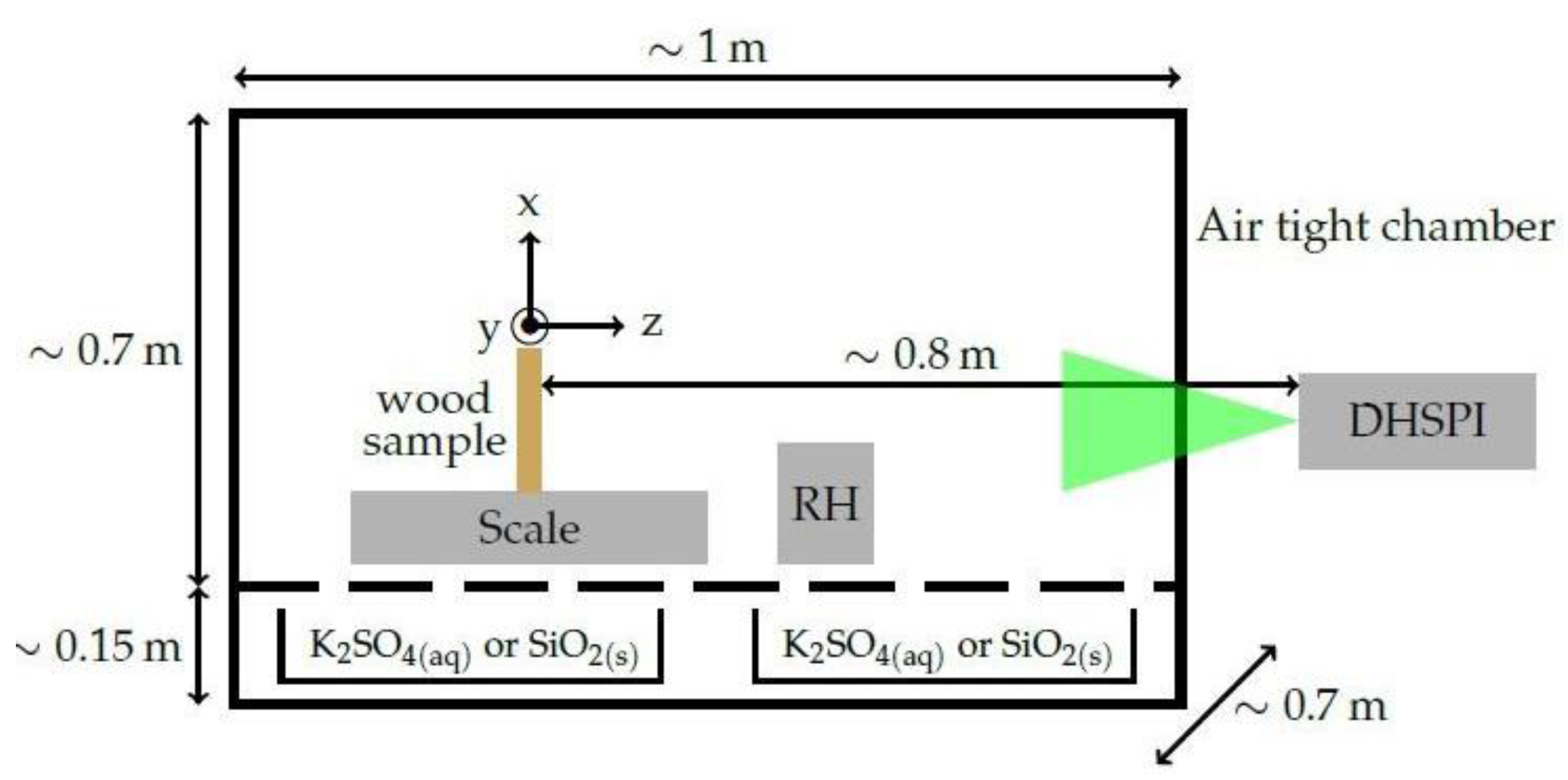
The DHSPI climate chamber workstation monitoring is an air-tight climate chamber measuring 100 × 850 × 700 cm with an extending metal frame carrying the DHSPI instrument. It is housed in laboratory conditions and consists of a salt-simulation-module inside the air-tight chamber that carries built-in cases to insert and alternate the salt solutions for the condition simulation and a vertical holder to mount the data loggers recording RH/T. At the other end of the climate chamber, facing the sample, is the monitoring module equipped with the interferometric DHSPI system at a distance to illuminate the full surface of the measured sample that is place free-standing on a weight-measuring scale, as it is shown in the schematic of Figure 3.
In the present experiment, the laser wavelength is λ = 532 nm, Δz is the displacement along the z-axis measured along the x,y-axis of fringe symmetry from the wrapped-phase interferograms and confirmed in some dubious interferograms by unwrapping the phase. The time interval between the recordings is set at Δt = 3–10 min, a parameter that changes, since it depends on the simulated ΔRH%.
The sample is set for several days in stable RH/T conditions inside the climate chamber before the change in RH condition is applied.
In the experiment, the evolution of three parameters is mainly studied:
  • The RH/T is measured in real-time with a hygrometer (accuracy ≈ 3%) and temperature logger placed inside the air-tight chamber (temperature resolution of 0.4 °C). To control the RH inside the chamber, saturated salt solutions of potassium sulphate (high RH) and silica gel as desiccant (low RH) are employed in long-term experiments.
  • The mass of the wood sample (placed in a free-standing position and taped on the scale) is measured in real-time with a precision of 1 mg.
  • The surface displacement of the sample along the z-axis (orthogonal to the surface) is monitored in real-time by DHSPI. The DHSPI portable device is on-axis with the sample outside the chamber and illuminates its full surface with an expanded laser beam (with expansion to cover the full size of sample).
  • With respect to the laboratory temperature outside the climate chamber during the experiments, the laboratory temperature is kept relatively constant, with smooth fluctuations from a minimum of 24 °C during some nights to a maximum 28 °C during some days. These variations are gradual with very low rate of change. Commonly, the laboratory conditioning ensures a temperature variation of max ±2 °C/24 h.
After the change in the salt solution, the recording of the sample reactions starts, while readings from the hygrometer, the temperature and weight are simultaneously acquired and electronically archived in specific software environments.

3. Simulation Methodology

The simulation methodology to monitor climate change’s impact on selected samples starts with the acclimatization of the sample measured to be in equilibrium when it is inserted in the chamber environment. Then it starts the cycling of RH change in a pre-specified condition and rate by inserting accordingly selected salts solutions to provoke the RH change inside the air-tight chamber at given values and the rate of change of RH.
The RH measurement range achievable in the chamber is 10–95% RH, measured with an accuracy of ±3% RH and a resolution of 0.5% RH. The temperature sensitivity range of the device is from −20 to 50 °C, with an accuracy of ±0.3 °C at 0–40 °C and a resolution of 0.1 °C. An interferogram is recorded every pre-specified time interval Δt and the phase φi of each hologram is extracted; the subtraction of two consecutive phases gives a phase difference Δφi, which is directly linked with the displacement occurred during Δt. The resulting interferograms represent the phase difference within the specified time interval.
It is noted that in these experiments, recorded prolonged sequences of holographic images and subsequent interferograms are not generated by the subtraction of each record from the initial one as in classical double exposure interferometry [39,40], but from the immediately preceding one [36,37,38]. The recording of data takes place while the RH is increased or decreased to provoke the reactions of the materials. The envisaged methodology allows imaging-relative displacements within specific time intervals and hence the estimation of the “rate of change” of material reactions within specific environmental changes. The methodology proves very useful in dynamic effect visualization and is suitable for environmental impact assessment.
Prior to start the cycling process, preliminary interferometry examination of the sample structural condition is performed to get knowledge on any existing structural problems and to measure the reference rest condition. This initial step provides the a-priory knowledge about existing defects as a baseline of the measurement and the whole-body reaction that, before the salts, is no more than a set of fringes in 10 min intervals. At any step of the experimental methodology, the RH and mass readings are automatically stored.
The importance of the method is found in sequential interferometry monitoring directly from the body surface visualising and quantifying the dimensional changes from climate impact. Full-field interferometry of surfaces, through direct real-time recording of surface images from delicate hygroscopic surfaces as they respond to RH changes, allowing interferometry data to be used in developing preventive strategies through the certainty of distinct quantifiable surface reactions. A surface is recorded while the RH changes, resulting in dimensional changes as a new equilibrium moisture content is aimed to be reached. The consequence of the structure’s natural reaction to the surrounding environmental conditions is dimensional displacement and as such the generation of temporally differentiated surface images representing a time-sequence of minute spatial alterations is possible with interferometry. Spatial displacement is due to the moisture absorption/desorption processes of the material.
Moisture content (MC) measurements require destructive actions or physical contact with the surface, interfering with the measurement action and affecting the genuine sample reaction. Organic materials are constantly interacting with the environment, and the importance in cultural heritage preventive deterioration is to have such a stability that minimises structural movements that provoke damage and not natural structural movement in general requiring heavy and expensive climate control. In museums, there are sensors to measure the RH of the environment, ensuring that they are maintained and allow only minor fluctuations. It is the environment that is measured, not the impact on the artwork.
In our experiments, the MC value is indicated from the weight of the sample that is placed throughout the measuring time on the top of a scale and the RH sensor. Any changes are attributed to adsorption or desorption of moisture according to the readings of the sensor and are correlated to the RH value and, in particular, the increase or decrease of RH provoking swelling and shrinking of the wood material surface. The consequence of the phenomenon is seen in the full-field optical displacement evident by changes in fringe number and density.
It should be also emphasized the requirement of high interferometric sensitivity in out-of-plane phase differs with small displacements. Speckle interferometry and speckle photography are mostly sensitive to in-plane displacement that cannot capture out-of-plane information. The out-of-plane displacement happens dominantly in the z-axis and interferometer geometry is required to be sensitive in z direction.
The phase difference is wrapped in the interference fringes. Phase information is not directly imaged by any available sensor due to the high frequency of light wavelengths, but it is visualised as phase differences in the fringes generated through interferometry. Fringe processing algorithms are commonly used to extract the phase from interference fringes to deliver the phase information. There are phase unwrapping algorithms to automatically process interferograms. This is performed through an automated or interactive process used in algorithms to process fine filtering and measure interference fringes. However, the automated algorithms are limited by the complexity of interference patterns, resulting in considerable errors, while the interactive requires processes of corrections onto the skeletonized fringe patterns which are lengthy and also prone to human error. In our methodology, the problem of unwrapping tenths of hundreds of interferograms required in environmental monitoring is avoided by the employment of the filtered wrapped phase interferogram and the extracted intensity profiles that are used to measure the fringes and deliver the total number of fringes of each interferogram. The number of fringes provides the N number for the functions to graphically represent the evolution of the physical process that the material experiences. Hence, the total number of fringes delivered is measured in micrometres to assign a single number as the displacement value, representing the displacement of the full surface in the time window and the ΔRH of each interferogram. Each simulation delivers big data numbers and intensity profiles facilitate fringe number measurements.

4. Results

Using the described workstation and monitoring method, several simulation experiments have been performed and characteristic results are described in next paragraphs.

4.1. Short-Term Monitoring: Rapid Dimensional Reactions

In this experimental work, the fundamental required evidence was how fast a sample “realises” the environmental change and how long it takes to react by starting the equilibrium process.
As one of the many preliminary investigations on capturing directly from materials, the response to environmentally induced changes is presented as an experimental measurement based on the monitoring and analysis of a model panel painting following isothermal changes in RH from 75%, created with NaCl saturated solution, to 44% RH, associated with the desorption of moisture and the contraction of the panel. A change from 10.5%, created with silica gel, to 44% RH was associated with the absorption of moisture and the expansion of the panel [27].
For the model painting, being under contraction condition resulted in shrinking dimensional effects, and expansion condition resulted in swelling dimensional effects. The interference fringe density measurement reveals the associated displacement monitored continuously over the first 300 s following the change in conditions. The start-up reaction of the sample is interferometrically noticeable from the very first second. The reaction throughout the 300 s monitoring shows an indication of submicron displacement until 15 s, with a displacement and development of the first successful fringe formation, and thus 0.265 microns, 16 s after the environmental change.
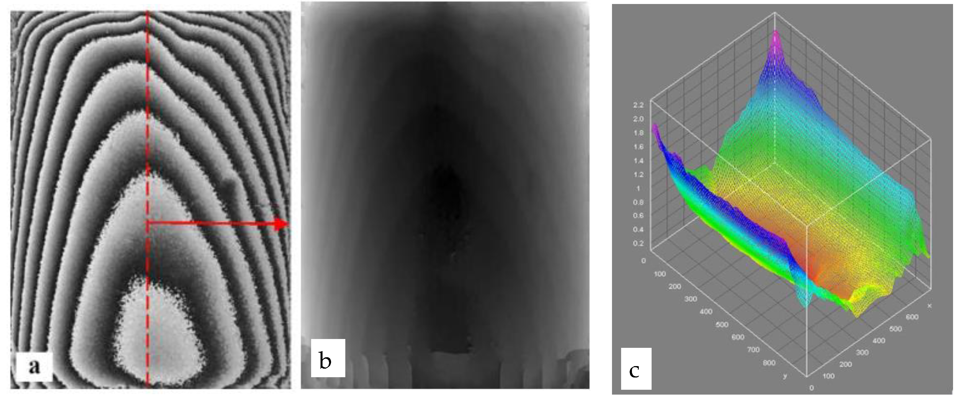
Thereafter, a displacement of 0.265–0.5 µm every second occurs until around 200 s, where a plateau of an average displacement of 3 µm is reached. A plateau was recorded following more than 300 s after the induced humidity change. The relative displacement of each temporally defined interferometric response from the start of the process has been calculated by the number of symmetric fringe-pairs in each interferogram. An example of the simulation process is shown in Figure 4, where an example of the swelling process of the interferogram, recorded 60 s after the climate change from 10.5 to 44% RH, is shown in its wrapped, unwrapped and 3D representation.
The fast reaction results reveal the absolute dependence of the movement of samples on environmental conditions. The surface reaction is recorded immediately, proving that the interaction of sample with the environment is instantaneous and displacement occurs at once as a reaction to the induced change.
In previous experiments with pulsed lasers, it was concluded that the speed of reaction and the displacement value is directly dependent on the rate of change providing a straightforward different reaction mechanism for small rates of change, characterised by long periods plateaus, and high rate of change without classifying reactions as slow or as abrupt surface changes. These movements are also experimentally proved as directly dependent on the direction of change (shrink-swell). The later experiments with DHSPI monitoring confirmed that fast impact and rapid reactions can be recorded even using CW lasers, facilitating application on museum floors [28].
Additionally, the importance of the full-field assessment of entire surface compared to other point-like measuring techniques or conventional strain-gauge methods is particularly advantageous as the entire surface can be examined and assessed simultaneously for all surface points. Although there is not theoretical limitation for beam expansion other than laser power, there is a practical limitation in the size of the climate chamber. Inside the currently-used chamber, the maximum surface imaged is up to 50 cm.
As the technique is directly quantitative, it allows temporal windows of relative displacement to be utilised relevant to the value of the induced change, as shown in the example in Figure 4 after 60 s from induced RH change. The interferogram represents the surface displacement following an abrupt climate change. The shown example is a transient position in a long process towards equilibrium, as the object accommodates the change in order to reach equilibrium with the surrounding environment over time, which may require several days to achieve. DHSPI measurement reveals that a rapid reaction follows whenever a change in RH occurs.
In studying the mechanism of deformation and ageing, it should thus be taken into account that a surface change independent of magnitude of RH change occurs immediately after any alteration in external conditions [29,30,31,32,33,34,35,36,37,38,39,40]. The materials react quickly, and delicate objects may be endangered from the constant movement to achieve EMC. Devoted experiments on testing the range of currently accepted RH/T museum values could highlight the effectiveness of the assumed safety values and rules that currently apply.

4.2. Long-Term Monitoring: Definition of Deformation Threshold Value (DTV)

Herein, the summarised long-term monitoring study aims to experimentally highlight long-term acclimatization behaviour, verifying through experimental data the accumulation of ageing signs and assess the assumed standards of RH safe ranges.
The envisaged experimental methodology is based on a newly introduced concept, during a CfC project, termed as “Deformation Threshold Value” (DTV) [37]. Each material or object exhibits distinct displacement values under same RH changes. These are assigned as a distinct deformation threshold value under specific RH cycles that is further defined as a baseline for accepted safe changes. The baseline of safety is derived from data directly recorded from investigated surface reactions. The displacements within the accepted baseline signify a range of displacement values that the deformation is considered to be within constant limits of displacement without endangering the integrity of the body. The threshold value is not taken theoretically or through indirect readings, but it is extracted from measured values of surface displacement under daily environmental change cycles. Thus, the surface is naturally provoked within its everyday environment to move, and its range of displacements provide the requested values. As long as the reactions are constant, and they produce values within these limits, the object condition is safe. Exceeding the constant reaction limits indicates the deformation threshold is violated, indicating new reactions with new values with potential for the surface integrity risks. As new values are re-established, the new values reset the alarm for risk warning.
During monitoring, the occurred microscopic optical path changes (L2) are simultaneously recorded interferometrically across the full surface.
The initial base displacement of the initial surface path while resting at equilibrium is assigned as d = Nλ/2, with N integer (number of fringe pairs, if the initial state is N = 0 then d = 0). When a displacement exceeds the initial base displacement condition and becomes d > Nλ/2, then the interferometry signal detects a displacement D. Displacement D is measured in half multiples of wavelengths in units of micrometres.
The surface position under the cycle changes, and the change in position provokes the microscopic optical path change (L2) that is a spatial condition change. If the spatial change is interferometrically captured with high-temporal resolution in quasi-real-time, the surface change is detected as a continuous temporal process of transient dynamic displacements. Starting from initial time t, a d = 0 is expected, and with no signal to assign a D to the surface, within the initial limits the surface is in zero fringe range or a couple of fringes in long intervals between data capturing: Dmax−Dmin = d=0.
Since the surface moves towards equilibrium, its D is not static. The transition between D min-max points of displacement is a gradual motion towards to these two points. Surface movement exhibits a displacement transition through an infinite number of potential surface positions. This dynamic phenomenon is captured through the interferometry records of its transient positions representing the surface motion.
In any of the positions, a relative displacement (RD) is recorded. The RD is dominated by the time interval between the capture of two transient positions. As RD is the change of the surface at any time—t = t1, tn−1—the comparison to the previous or initial reference state of the surface at t = 0 or t = 1, etc., is a differentiation among acquisition times corresponding to variety of surface spatial displacement positions, deriving:
Δ V V = ( d i + 1 d i ) x   ( L 2 ) d 0 x ( L 2 ) = d i + 1 d i d 0 = R D i + 1 R D i d 0 = Δ d d
When an RD is captured within a temporal window of time interval between surface positions, then the Rate of Displacement (RoD) is revealed.
RoD reveals how fast the surface reacts to any load that is applied as a function of time. When the RoD does not return in its reference position, even after the removal of the dynamic load, being the full cycle completion, the constant values principle of safe limits is violated and the result is detection of deformation.
Deformation is the change in the volume (ΔV) from the original volume (V), giving a range of constant values (even plateaus). These values, if exceeding the deformation threshold, collapses into a new displacement pattern with variability of values and the surface suffers a new condition, probably with a new deformation threshold, which can be irreversible or not, but as a new condition may bring the surface closer to ageing and/or new damage condition. The cycles of variability raise the behaviour of the variability values, the new threshold condition, the change in temporal windows and other parameters to define the onset of variability and its progression which are as yet unexplored; new experiments should be designed for this exploration.
RoD is introduced in our methodology since it is a parameter better suited to calculate deformation over time in long periodic monitoring than the relative displacement or strain that provide absolute numbers with scalar properties. The rate of deformation that is acceleration/time is suitable to record, in specific temporal windows, the reaction of the surface to the induced impact over long periods of time, providing a deformation threshold validation and thus updating the range of safe fluctuations for each specific artwork. The comparison of RoD from a surface in same measurement parameters can be archived and compared over decades, and graphs of risk can result in an early warning alarm in preventive conservation to serve as guidelines over years.
Samples: The samples here are fresh cut wood specimens. They are categorized according to two wood densities, softwood and hardwood, and thicknesses from 1–5 cm. The samples cover a range of sensitivities to environmental change. The cycles of RH were taken from true values of different locations with different environmental characteristics across Europe. The RH cycles are chosen from the yearly RH monitoring from the day with the maximum fluctuation, since it is expected to be the day with the strongest impact on the hosted artworks. In this way, a classification index of environmental sensitivity can be formed for different locations with the impact on the wood’s DTV.
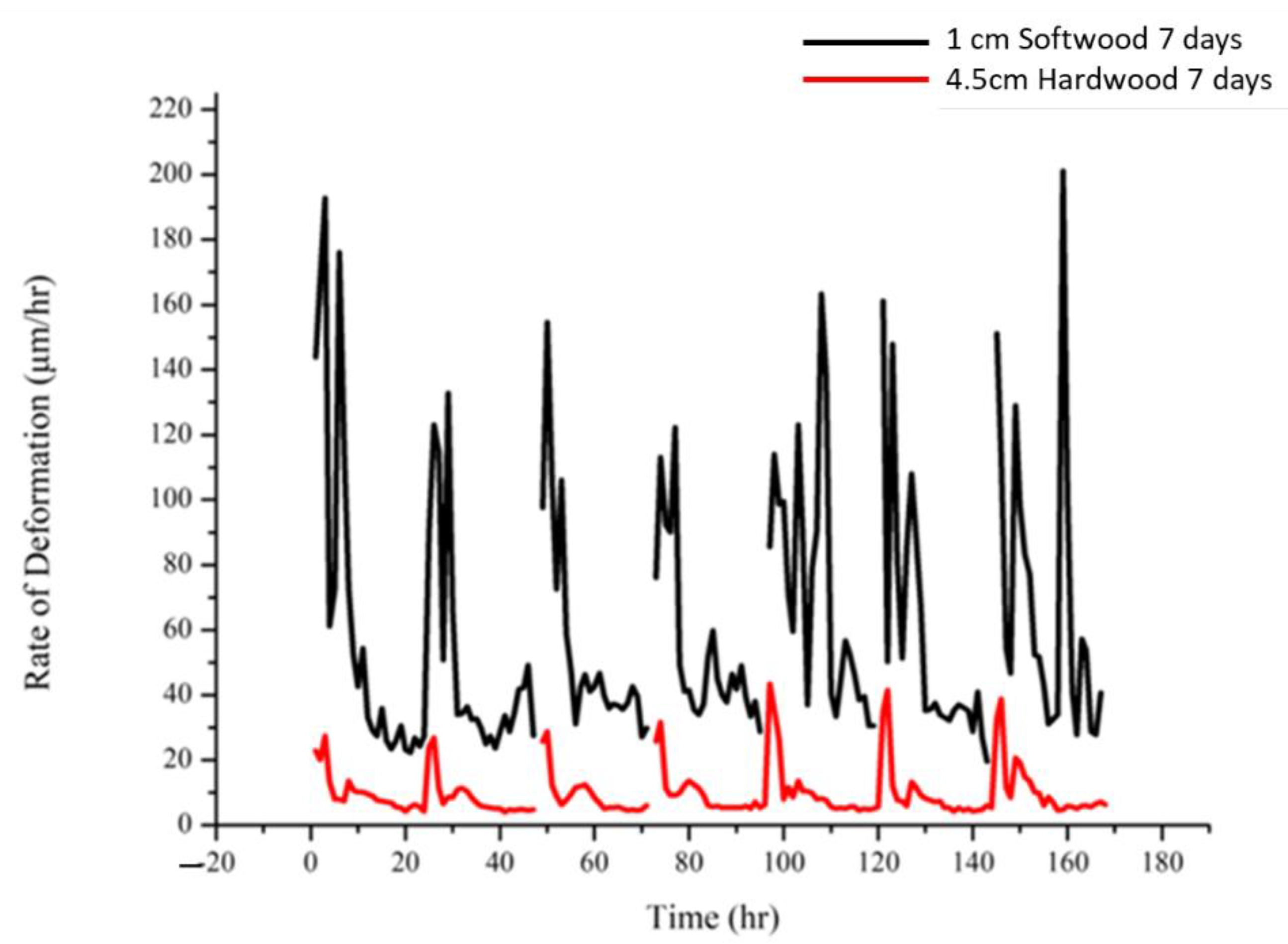
The graph in Figure 5 shows the RoD values of the 4.5 cm hardwood sample for the 7 days of cycling, as well as the corresponding 7 days of 1 cm softwood recorded for 18 cycles in total. The difference in values, as well as in the density and frequency (variability) of occurrence of large RoD values, between the two samples is very large.
The maximum value of 1 cm is 201 μm/h, while the maximum value of the 4.5 cm sample is 43 μm/h.
Based on the RoD values, the threshold value of 1 cm softwood was set at 55 μm/h and for 4.5 cm hardwood at 10 μm/h.
Deformation of the samples at the end of each hour of each 24-h cycle was also calculated.
Based on the above, a “risk-index” tool is formulated and an “alarm” algorithm could be developed for museums’ use, to read the DTV and RoD from for a variety of several fragile or precious artworks inside the galleries, and to always be ready to inform the curators.
Based on the above, the long-term RoD values, as calculated distinctly for each sample, are statistically graded into different categories:
(a)
RoD corresponds to a deformation below or at the edge of threshold value;
(b)
RoD corresponds to a deformation greater than the mean;
(c)
the RoD measurements are greater than the threshold value, but do not correspond to a distortion greater than the absolute mean.
For the average of the absolute values of the deformations, the diagrams in Figure 6 were obtained.
The percentage of RoD values below the threshold value decreases significantly to almost 25% after the seventh day, while the percentages above the threshold value almost double and the change in RoD values (variability) becomes apparent.
In red, we see the rate of deformation for all 24 h of the cycle, while in blue, the values are only to which Δd/d > average of the absolute values of the deformations correspond. We notice that in the majority, the large value of the rate corresponds to a distortion greater than the mean values.

Brief Conclusions on Long-Term RoD Dependencies

At 18 days of the experimental cycle, the sample showed no defects visible to the naked eye. After the sixth day, it shows intense internal activity due to the changes of RH, which is perceived both by the increased frequency of the occurrence of large values of RoD and, respectively, by the increased frequency of large values of deformation. This phenomenon begins to decrease after the 13th day of cycling, which leads to the conclusion that the sample tends to equilibrium within the environmental conditions in which it is located.
As the intense rate of change of deformation, meaning the increase of the frequency of the occurrence of large values, RoD traces the onset of variability reactions and leads to the conclusion that a change in the structure of the sample occurs either sub-superficially or internally—although it is not yet capable of producing visible damage such as a crack that is expected under cycling of shrinking-swelling patterns. This variability trend development occurs only in the long-term, where repetitive changes in RH and periodic 24-h cycles are applied to the sample. The variability pattern seems to be a critical turn leading to deterioration and should be further investigated.
In order to generate a mathematical model and develop the essential algorithms for automatic routine monitoring for preventive conservation, the cycling experiments should be repeated for as long as needed until fracture, proving visible damage occurs. Repetition and characteristics of variability in increasing values should be explored.

4.3. RoD Relation to Sorption Isotherms

Further studies are presented on the possibility of differentiation of displacement rates in relation to the surrounding environment, as wood samples are forced by RH to follow the cycles of sorption isotherm and hysteresis under constant climate-chamber temperature (T °C) [37,38]. In the present experiments, the time interval between the recording of two holograms is set at Δt = 3 min, the laser wavelength is again λ = 532 nm and Δz is the displacement along the z-axis, while fringe measurement is performed from 0 order fringe along the axis of fringe symmetry distribution. Further details on the method with which the number of fringes (N) is determined from an interferogram can be found elsewhere [37,38].
Previously, it has been shown that the measurements allow us to capture shrinking and swelling of a range of wood samples due to environmental alterations to RH. Since the wood surface as a reaction to RH is just a few μm, the technique that measures in multiples of half-wavelengths provide the highest possible sensitivity to visualize and study the reaction of the material. Imperceptible internal changes in wood structure can be detected by witnessing the procedure of the ageing of wood. In this context, the phase difference within specific time intervals indicates the rate of change of the surface and hence is linked to the rate of displacement. To determine the rate of surface deformation (RoD) as a response to environmental fluctuations within a period of time, the RoD is deduced from the direct measurement of the number of fringes N of each interferogram. We have seen that:
R o D = Δ z Δ t = N λ 2 Δ t
Since the results of the non-contact, direct surface measurement technique are encouraging to the aim of further understanding the mechanisms of onset of fatigue, the experiments are further carried out towards the recording of the cycle of the absorption and adsorption mechanisms of wood. This is performed by studying the evolution of the equilibrium of moisture content as a function of the RH in a laboratory environment with constant temperature. The analysis of the reaction in a sorption isotherm graph has been reported [38].
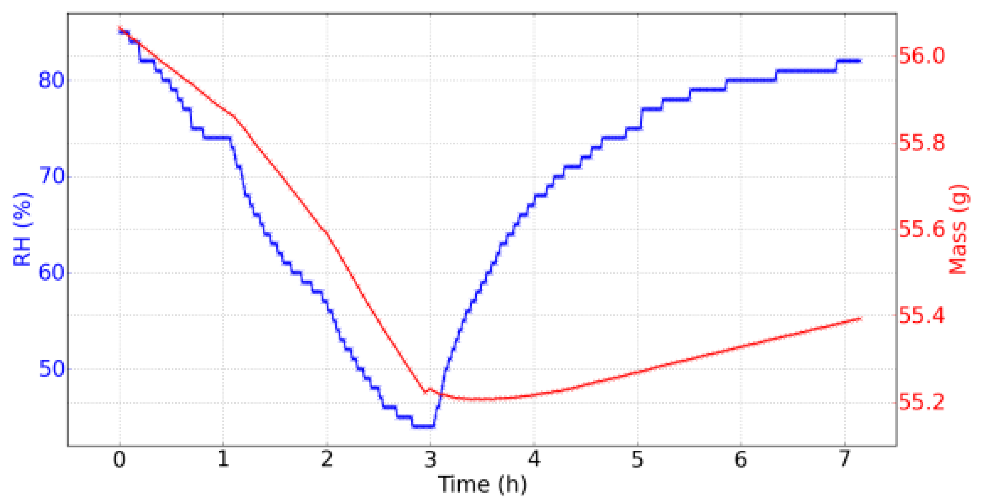
In this experiment, the saturated salt solution of potassium sulphate alternated with silica gel provide a cycle of 85% RH to 44% RH in three hours, then a return in 82% RH in four hours is reached. During drying, the evolution is nearly linear. During rehydration, the evolution is followed an exponential rising curve, becoming more and more slow. In Figure 7, the evolution of the RH and the mass of the wood sample during day 7 is shown. The amplitude of variation of the mass is 0.86 g. It is observed that, during the drying out process, the mass follows the RH and their temporal evolutions are similar, while during rehydration, the mass evolved slower with an almost linear evolution of 0.057 g/h rate change (over the last three hours). Moreover, a “rebound” in the evolution of mass was observed when the RH began to increase: mass reached its minimum after the RH had reached its minimum. This time lag was equal to:
Δt = tMmin − tRHmin = 34 min.
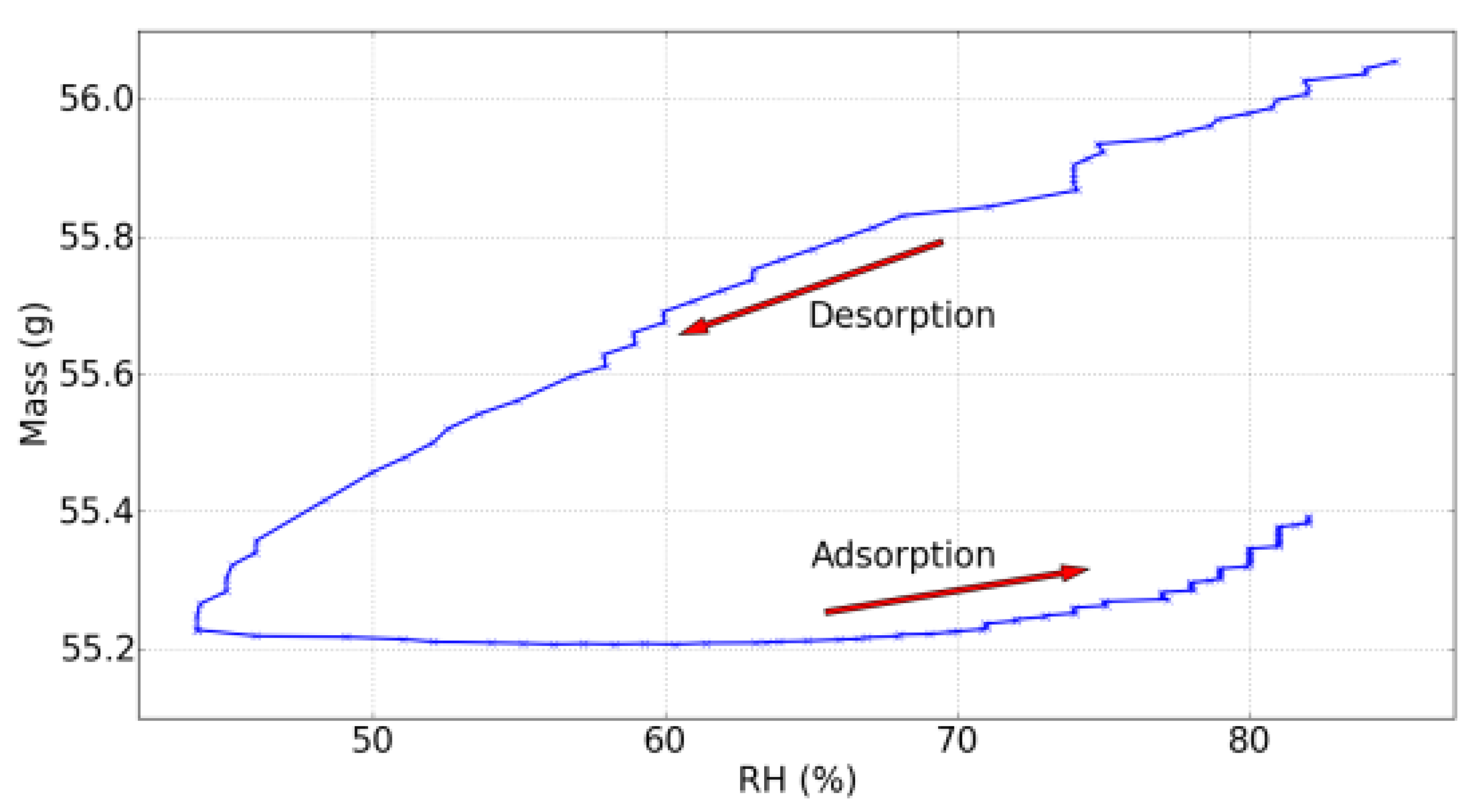
With the available data, the dynamic sorption isotherm at non-equilibrium could be plotted and is shown in Figure 8. A hysteresis is witnessed due to the mass that did not follow the same RH rate change during the rehydration, but rather increased with another characteristic shape linked with this specific evolution of the RH.
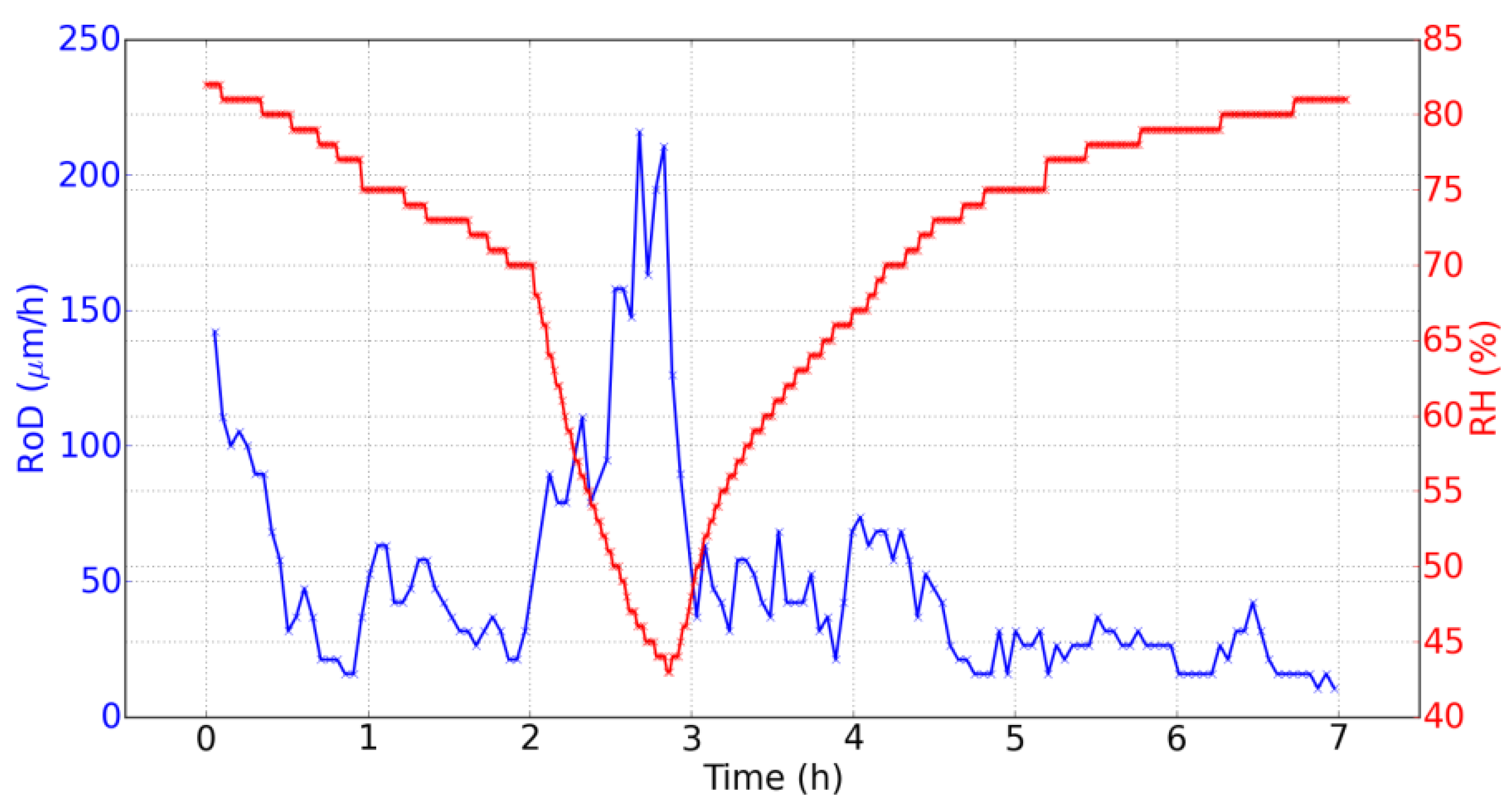
Two main points regarding the temporal evolution of the RoD can be observed at Figure 9.
  • The RoD is clearly greater during drying. It shows the great difference between the two phenomena of drying and rehydration, linked with the hysteresis of the dynamic sorption isotherm (Figure 8).
  • During drying, the RoD is greater after one hour and a half when the RH decreased faster. At the beginning of the rehydration, the RoD is more significant during the first thirty minutes, and then fell as the RH evolved more and more slowly. Therefore, the RoD seems to be correlated with the temporal derivative of the RH. The faster the RH changes, the higher the RoD is.
  • This effect is better demonstrated on the data from day 2, shown in Figure 10, where two different temporal evolutions of the RH during drying can be noted.
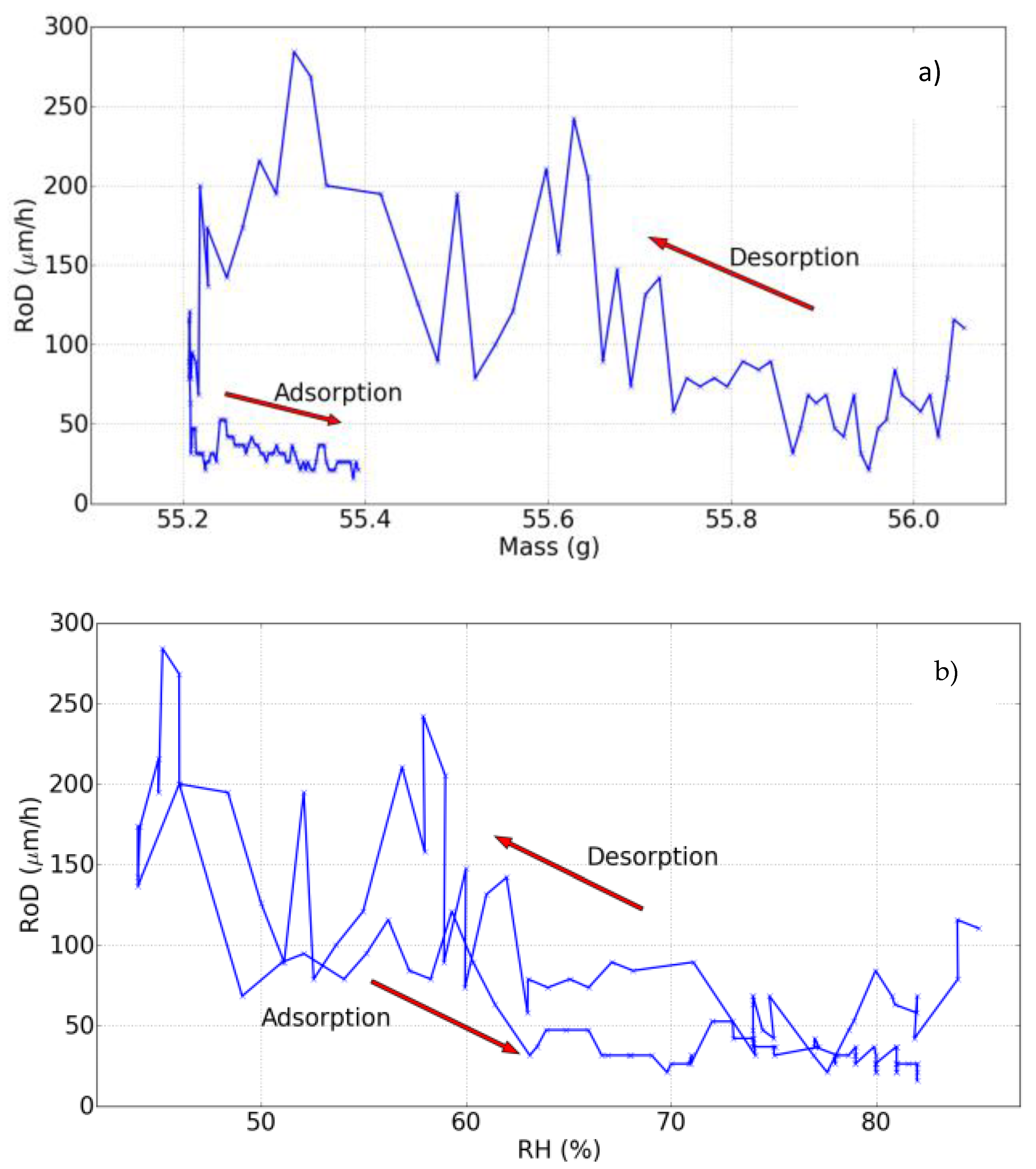
Next, the RoD is plotted as a function of mass shown in Figure 11a and of the RH as shown in Figure 11b, in the same way as the dynamic sorption isotherm (Figure 11). These curves are characterized by hysteresis too.
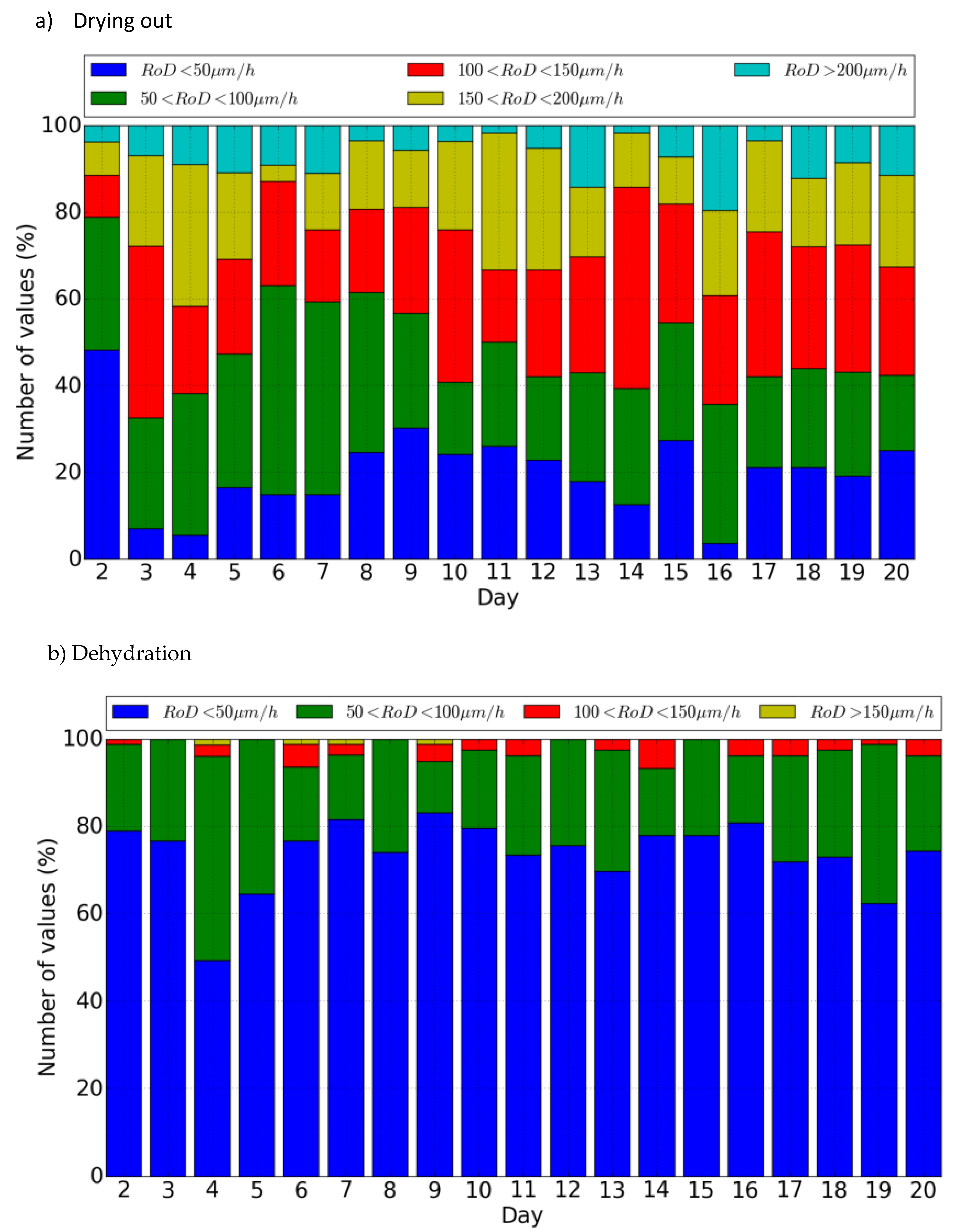
During the long-term experiments, similar evolutions with the same characteristics that are explained above have been observed. There does not appear to be the establishment of new variabilities in these evolutions. Figure 12a,b shows the plotted bar plots of the number of values in given intervals of the RoD in order to see any evolution, for instance, an increase of the number of high RoDs during drying out (Figure 12a) or dehydration (Figure 12b), (bottom to top) if to observe any significant variations within the non-fracture period. It is thus recommended for longer-term monitoring to be continued for an unknown period until evolution of cracks/fracture is observed to complete a full experimental observation.

5. Conclusions

This paper has presented interferometry experimental data gathering from direct surface illumination in full field for monitoring RH impact.
The hypothesis and methodology provide fruitful ground for research and substantial evidence that a direct quantitative interference fringe measuring method of assessing optical displacement, and correlating it to physical values, provides an efficient and necessary direct tool to investigate complex physical phenomena in environmental effects in cultural heritage objects.
The objectives of the experimental research studies implemented in the monitoring workstation were founded with the aim of characterizing the behaviour patterns of ageing, especially as a result of environmental fluctuation of RH. This was mainly with wood materials submitted to RH cycles into a climate chamber, where simulation can be interferometrically monitored in real-time directly from the surface.
A new experimental approach to define deformation threshold values with direct full-field surface monitoring in an automatic, non-contact and remote real-time mode has been presented. The results are consistent and repeatable through the experimental course, from preliminary fast reactions experiments to the advanced long-term cycling and physical quantities correlation. There have been indicative examples chosen from a full set of samples implemented in the study. The lab simulation experiments are an ongoing progress and each experiment is used to improve the next experimental phase.
With regard to long-term cycling, the experimental data and analysis allows confirming theoretical axioms and mathematical simulations for the following main conclusions, which can be confirmed until the moment of writing:
A dry environment provokes higher deformation on wood.
Softwood exhibits higher values of displacement and rate of deformation than hardwood.
Thickness is a dominant parameter with thin samples, expressing higher values of RoD and displacement.
Density is the second dominant parameter, with wood cut not yet classified (tangential exhibits higher displacement than radial; examples have not been shown here).
Threshold value is different for each measured sample.
It is experimentally aimed to define a strain rate above which will it not be considered a safe environmental condition, despite the fact that the conditions can be stable (ΔRH < 5%). It is not the value of the rate of deformation that concerns the deformation risk but the variability in frequency and amplitude over the safe zone (threshold value of RoD). Hence, it is also experimentally aimed to define frequency and amplitude of the rate that corresponds to the deformation risk.
Concerning the mass, it is observed that it adapted fast to the RH during the drying process, a phenomenon directly linked with the well-known hysteresis of the sorption isotherm, which is observed in the dynamic sorption isotherm. The measurements with DHSPI have enabled us to measure the rate of displacement of the surface due to the variation of the RH. A high RoD is observed during the drying and a lower RoD during the rehydration, an observation that illustrates again the difference between the drying and the rehydration process. Moreover, the RoD seems to correlate with the temporal rate of evolution of the RH, showing a dependent relation with temporal derivative of the RH.
The long-term experiments showed that, during several days, observed systematic reactions and a behaviour pattern of the material, which has been described. Past experiments have showed that this statement can be claimed for many different types of materials and complex samples. The DHSPI system is confirmed to be an effective recording system for monitoring reactions to environmental impact directly from the examined object.
In the abrupt high ΔRH experiments of hourly cycling evolution of the mass presented a clear offset, whose evolution seemed to be linked with ageing of wood. No significant variation in the evolution of the RoD is observed. Future experimental data are to be collected with samples to be kept under constant RH cycles during consecutive days until variability and irreversible damage occurs. The aim is to study the ageing of wood under true conditions where, as in the real case scenarios, the RH fluctuations, within a number of different values, are the undisputed everyday reality. It is designed to also submit the wood sample to faster RH cycles, with smaller time windows between the minimum–maximum values in order to simulate more and faster RH variations in cases of extreme climate events where there is also evidence of visualizing very interesting reactions and the tracing of invisible physical phenomena.
With respect to the monitoring system, it is confirmed that DHSPI enabled us to measure the displacement of the surface of wood samples when it swells and shrinks due to variations of the RH. This technique is highly relevant to this study for many important reasons. DHSPI allows for a high accuracy of the order of half-wavelength (λ = 532 nm), with the displacements of the wood surface being of the order of some μm. It thus signifies that imperceptible external or internal changes can be detected (non-visible to the naked eye and to other known techniques employed in conservation or other fields) due to ageing of wood. Moreover, this technique records automatically in pre-specified intervals in a non-contact, non-invasive, non-destructive and full-field manner, all of which offer great advantages to in-situ measurements of material deformations and to the study of artworks and historical buildings in response to their environmental surroundings, since they are based on an optical technique that does not have shape or surface roughness limitations. The DHSPI technique also enables us to measure real-time displacement and to do a full-field surface monitoring of complex 3D objects. It is very important that DHSPI records out-of-plane displacement that is a more relevant component in dimensionally responsive materials escaping from measurement by other techniques. Finally, the rate of deformation (RoD) provides a value that can be classified to provide an early warning signal of deformation for preventive conservation strategies in cultural heritage protection.
Software improvement to achieve fast automation of data processing from interference fringe patterns are in progress through developments based in Sine-Cosine Average (SCA) with Stationary Wavelet Transform (SWT).
The results validate the DHSPI technique as a direct surface monitoring method to investigate imperceivable phenomena and aid the understanding of physical mechanisms, while DTV can be very useful towards the decisive prevention strategies on collections and monuments.
With development of the presented methodology and instrumentation, the aim is to finally correlate the physical values and provide a fully non-contact and non-destructive method for direct environmental impact assessment in the museum environment.

Funding

This research was funded by European project Climate for Culture https://www.climateforculture.eu/ and supported in part by the European Union’s Horizon 2020 research and innovation programme LASERLAB-EUROPE under Grant Agreement No. 871124.

Acknowledgments

From this position, author wishes to thank: former colleagues and co-operators in this study, especially Eirini Bernikola, Nota Tsigarida and Thomas Basset for their persistent devotion in these experiments. The European project Climate for Culture (CfC) (https://www.climateforculture.eu/ accessed 10 October 2022) that allowed long-term experiments and the “Deformation Threshold Value” concept to be tested and the coordinator Johanna Leissner for her support throughout the years. The experimental work was conducted at the Holography Metrology laboratory at the Institute of Electronic Structure and Laser (IESL) and partial funding has been derived also from Ultraviolet Laser Facility at FORTH-IESL, LASERLAB-EUROPE under Grant Agreement No. 871124.

Conflicts of Interest

The authors declare no conflict of interest.

References

  1. Depolo, G.; Walton, M.; Keune, K.; Shull, K.R. After the paint has dried: A review of testing techniques for studying the mechanical properties of artists’ paint. Herit. Sci. 2021, 9, 68. [Google Scholar] [CrossRef]
  2. Thomson, G. The Museum Environment, 2nd ed.; Butterworth-Heinemann: Oxford, UK, 1990. [Google Scholar]
  3. Michalski, S. Paintings—Their Response to Temperature, Relative Humidity, Shock, and Vibration B. In Art in Transit: Studies in the Transport of Paintings; National Gallery of Art: Washington, DC, USA, 1991; pp. 223–248. [Google Scholar]
  4. Michalski, S. Relative Humidity: A Discussion of Correct/Incorrect Values. In Proceedings of the ICOM Committee for Conservation Tenth Triennial Meeting, Washington, DC, USA, 22–27 August 1993. [Google Scholar]
  5. Mecklenburg, M.F.; Tumosa, C.S.; Erhardt, D. Structural Response of Painted Wood Surfaces to Changes in Ambient Relative Humidity. In Painted Wood History and Conservation; Getty Conservation Institute: Los Angeles, CA, USA, 1994; pp. 464–483. [Google Scholar]
  6. Mecklenburg, M.F.; Tumosa, C.S.; Wyplosz, N. The effects of relative humidity on the structural response of selected wood samples in the cross-grained direction. Mater. Res. Soc. 1995, 352, 305–324. [Google Scholar] [CrossRef]
  7. Martens, M. Climate Risk Assessment in Museums; Technische Universiteit Eindhoven: Eindhoven, The Netherlands; Ipskamp Drukkers: Enschede, The Netherlands, 2012; ISBN 978-90-6814-645-5. [Google Scholar]
  8. Krzemień, L.; Łukomski, M.; Bratasz, Ł.; Kozłowski, R.; Mecklenburg, M.F. Mechanism of craquelure pattern formation on panel paintings. Stud. Conserv. 2016, 61, 324–330. [Google Scholar] [CrossRef]
  9. Roche, A.; Soldano, A. The effect of changes in environmental conditions on the mechanical behaviour of selected paint systems. Stud. Conserv. 2018, 63 (Suppl. S1), 216–221. [Google Scholar] [CrossRef]
  10. BSD Moisture and Materials by John Straube. 2006. Available online: https://buildingscience.com (accessed on 15 May 2019).
  11. Skaar, C. Wood-Water Relations; Springer: Berlin/Heidelberg, Germany, 1988. [Google Scholar]
  12. Meier, H. Chemical and morphological aspects of the fine structure of wood. Pure Appl. Chem. 1962, 5, 37–52. [Google Scholar] [CrossRef]
  13. Scallan, A.M. The structure of the cell wall of wood: A consequence of anisotropic inter-microfibrillar bonding? Wood Sci. For Prod. Res. Soc. 1974, 6, 266–271. [Google Scholar]
  14. Bucur, V. Springer Series in Wood Science; Springer: Berlin/Heidelberg, Germany, 2003. [Google Scholar]
  15. Chomcharn, A.; Skaar, C. Dynamic sorption and hygroexpansion of wood wafers exposed to sinusoidally varying humidity. Wood Sci. Technol. 1983, 17, 259–277. [Google Scholar] [CrossRef]
  16. Eckelman, C.A. The shrinking and swelling of wood and its effect on furniture. For. Nat. Resour. 1998, 163, 1–26. [Google Scholar]
  17. Lankester, P.; Brimblecombe, P. The impact of future climate on historic interiors. Sci. Total Environ. 2012, 417–418, 248–254. [Google Scholar] [CrossRef] [PubMed]
  18. Bylund Melin, C.; Hagentoft, C.E.; Holl, K.; Nik, V.M.; Kilian, R. Simulations of Moisture Gradients in Wood Subjected to Changes in Relative Humidity and Temperature Due to Climate Change. Geosciences 2018, 8, 378–392. [Google Scholar] [CrossRef] [Green Version]
  19. Camuffo, D.; della Valle, A.; Becherini, F. A critical analysis of one standard and five methods to monitor surface wetness and time-of-wetness. Theor. Appl. Clim. 2018, 132, 1143–1151. [Google Scholar] [CrossRef]
  20. Camuffo, D.; Van Grieken, R.; Busse, H.J.; Sturaro, G.; Valentino, A.; Bernardi, A.; Blades, N.; Shooter, D.; Gysels, K.; Deutsch, F.; et al. Environmental Monitoring in Four European Museums. Atmos. Environ. 2001, 35, S127–S140. [Google Scholar] [CrossRef]
  21. Noah’s Ark Project 2007. D12—Production of the Vulnerability Atlas and Deliverable 15—Freely Available Guidelines on Adaptation of Cultural Heritage to Climate Change; EU 6th Framework Program, Project No. SSPI-CT-2003-501837-NOAH’S ARK. Available online: https://cordis.europa.eu/project/id/501837/reporting (accessed on 10 October 2022).
  22. Climate for Culture Project. Available online: https://www.climateforculture.eu/index.php?inhalt=dissemination.publications (accessed on 15 May 2019).
  23. Yu, Y.; Zhou, W.; Yannis, O.; Tornari, V. Phase shifting digital holography in image reconstruction. J. Shanghai Univ. 2006, 10, 59. [Google Scholar] [CrossRef]
  24. Bernikola, E.; Nevin, A.; Tornari, V. Rapid initial dimensional changes in wooden panel paintings due to simulated climate-induced alterations monitored by digital coherent out-of-plane interferometry. Appl. Phys. A 2009, 95, 387–399. [Google Scholar] [CrossRef]
  25. Tornari, V.; Bernikola, E.; Nevin, A.; Kouloumpi, E.; Doulgeridis, M.; Fotakis, C. Fully non-contact holography-based inspection on dimensionally responsive artwork materials. Sensors 2008, 8, 8401–8422. [Google Scholar] [CrossRef] [PubMed] [Green Version]
  26. Tornari, V.; Bernikola, E.; Tsigarida, N.; Hatzigiannakis, K.; Andrianakis, M.; Leissner, J. Measuring environmental impact by real time laser differential displacement technique in simulated climate conditions. In Proceedings of the SPIE 9527, Optics for Arts, Architecture, and Archaeology V, 95270R, Munich, Germany, 24–25 June 2015; Pezzati, L., Targowski, P., Eds.; SPIE: Bellingham, WA, USA, 2015. [Google Scholar]
  27. Tornari, V.; Bernikola, E.; Bellendorf, P.; Bertolin, C.; Camuffo, D.; Kotova, L.; Jacobs, D.; Zarnic, R.; Rajcic, V. Surface monitoring measurements of materials on environmental change conditions. In Proceedings of the SPIE 8790, Optics for Arts, Architecture and Archaelogy IV, Munich, Germany, 15–16 May 2013. [Google Scholar]
  28. Tornari, V.; Bernikola, E.; Osten, W.; Grooves, R.M.; Georges, M.; Cedric, T.; Hustinx, G.M.; Kouloumpi, E.; Moutsatsou, A.; Doulgeridis, M.; et al. Multifunctional encoding system for assessment of movable cultural heritage. In Proceedings of the 7th International Conference on Lasers in the Conservation of Artworks (LACONA VII), Madrid, Spain, 17–21 September 2007; Taylor and Francis Group: London, UK, 2008; pp. 381–386. [Google Scholar]
  29. Bernikola, E.; Tornari, V.; Nevin, A.; Kouloumpi, E. Monitoring of changes in the surface movement of model panel paintings following fluctuations in relative humidity; preliminary results using digital holographic speckle pattern interferometry. In Proceedings of the 7th International Conference on Lasers in the Conservation of Artworks (LACONA VII), Madrid, Spain, 17–21 September 2007; Taylor and Francis Group: London, UK, 2008; pp. 391–397. [Google Scholar]
  30. Groves, R.M.; Osten, W.; Doulgeridis, M.; Kouloumpi, E.; Green, T.; Hackney, S.; Tornari, V. Shearography as part of a multi-functional sensor for the detection of signature features in movable cultural heritage. In Optical Metrology; Fotakis, C., Pezzati, L., Salimbeni, R., Eds.; John Wiley & Sons: Munich, Germany, 2007; p. 661810. Available online: http://proceedings.spiedigitallibrary.org/proceeding.aspx?doi=10.1117/12.727497 (accessed on 26 October 2022).
  31. Kalms, M.K.; Jueptner, W.P.O. A mobile shearography system for non-destructive testing of industrial and artwork components. Key Energy Mater. 2005, 295–296, 165–170. [Google Scholar] [CrossRef]
  32. Thizy, C.; Georges, M.P.; Kouloumpi, E.; Green, T.; Hackney, S.; Tornari, V. Photorefractive Holographic Interferometry for Movable Artwork Assessment. In Controlling Light with Light: Photorefractive Effects, Photosensitivity, Fiber Gratings, Photonic Materials and More; OSA Technical Digest (CD); Optical Society of America: Washington, DC, USA, 2007; p. MB49. [Google Scholar]
  33. Thizy, C.; Georges, M.; Doulgeridis, M.; Kouloumpi, E.; Green, T.; Hackney, S.; Tornari, V. Role of dynamic holography with photorefractive crystals in a multi-functional sensor for the detection of signature features in movable cultural heritage. In Proceedings of the SPIE 6618, O3A: Optics for Arts, Architecture, and Archaeology II, Munich, Germany, 17–18 June 2009. [Google Scholar]
  34. Tornari, V. Spatial Coordinates in Interferometry Fringes: A Timeless Artwork Multipurpose Documentation. J. Basic Appl. Phys. 2012, 1, 39–48. [Google Scholar]
  35. Tornari, V. On development of portable digital holographic speckle pattern interferometry system for remote-access monitoring and documentation in art conservation. Strain 2018, 55, e12288. [Google Scholar] [CrossRef]
  36. Tornari, V.; Bonarou, A.; Antonucci, L. Sequential holographic interferometric recording: A key to monitor dynamic displacements in long-term effects. In Proceedings of the 4th International Workshop on Automatic Processing of Fringe Patterns, Bremen, Germany, 17–19 September 2001; Elsevier: Amsterdam, The Netherlands, 2001; pp. 680–685. [Google Scholar]
  37. Tornari, V.; Bernikola, E.; Tsigarida, N.; Andrianakis, M.; Hatzigiannakis, K.; Leissner, J. Preventive deformation measurements on cultural heritage materials based on non-contact surface response of model samples. Stud. Conserv. 2015, 60, S143–S158. [Google Scholar] [CrossRef] [Green Version]
  38. Tornari, V.; Basset, T.; Andrianakis, M.; Kosma, K. Impact of Relative Humidity on Wood Sample: A Climate Chamber Experimental Simulation Monitored by Digital Holographic Speckle Pattern Interferometry. J. Imaging 2019, 5, 65. [Google Scholar] [CrossRef]
  39. Vest, C.M. Holographic Interferometry; John Wiley & Sons: Hoboken, NJ, USA, 1979. [Google Scholar]
  40. Jones, R.; Wykes, C. Holographic and Speckle Interferometry, 2nd ed.; Cambridge University Press: New York, NY, USA, 1989. [Google Scholar]
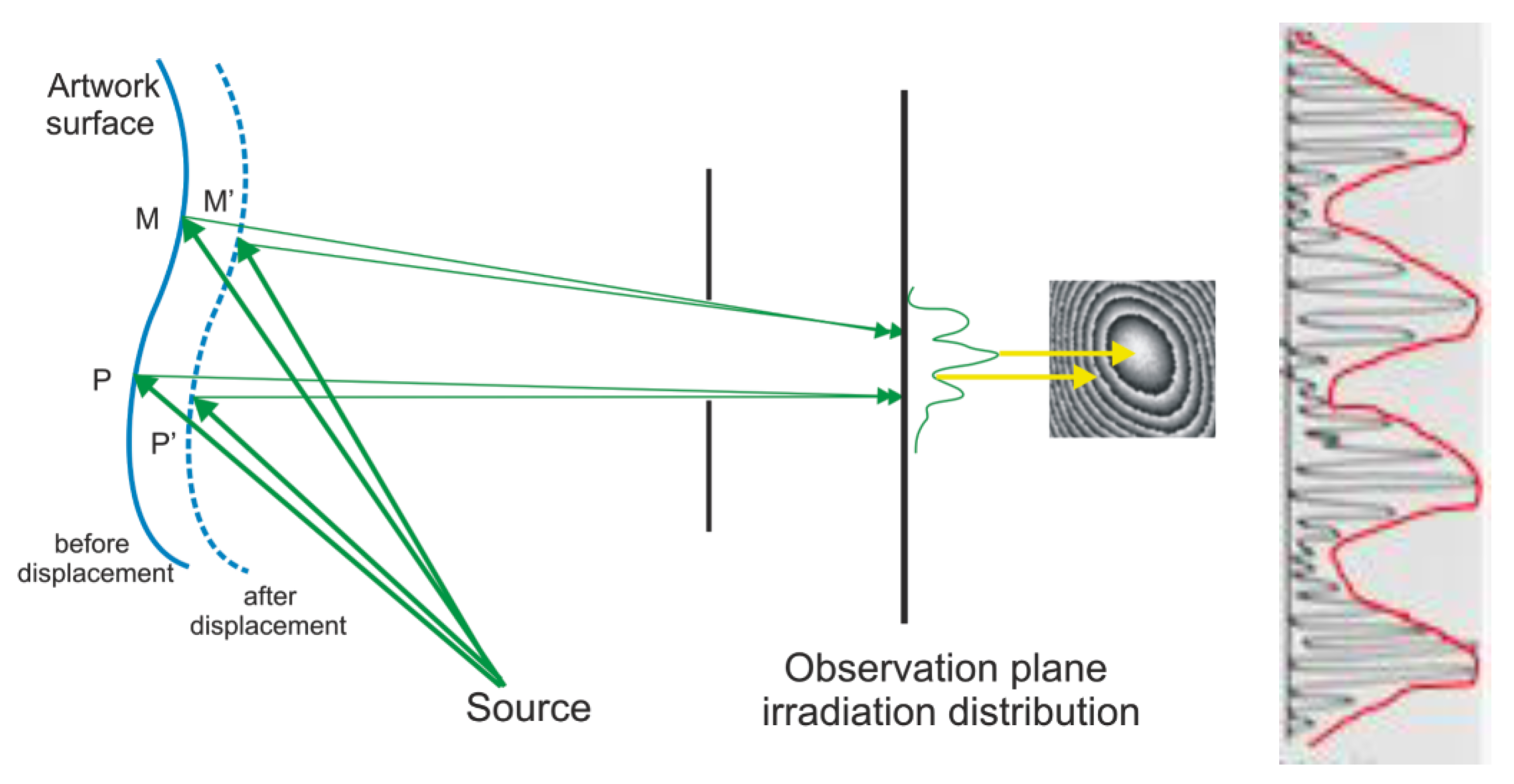
Figure 1. The interferometric comparison of two wavefronts scattered from a surface at initial and displaced positions. In insert the difference between speckle and interferometry fringes (M, P points before -M′P′ after).
Heritage 06 00009 g001
Figure 2. Implemented optical geometry of DHSPI system. M mirrors with last M3 carrying the PZT piezoelectric transducer.
Heritage 06 00009 g002
Figure 3. The simulation-monitoring climate chamber and DHSPI workstation. The green colour indicates the laser beam that propagates vertically from DHSPI system, facing the sample positioned on scale. Note on vertical holder the RH data logger while the salt-cases are seen on the bottom of the chamber (exemplary salts).
Heritage 06 00009 g003
Figure 4. (ac). Exemplary interferogram after 60 s of RH change. In (a) the wrapped interferogram, in (b) the unwrapped phase and in (c) the 3D map of surface deformation. Note the red lines showing the exhibited symmetry in characteristic tangential-cut pattern.
Heritage 06 00009 g004
Figure 5. The rate of deformation vs. time for two categories of wood sample, the black line for the most susceptible and the red line for least susceptible to displacement.
Heritage 06 00009 g005
Figure 6. In red the rate of deformation for all 24 h of the cycle, while in blue only the values to which Δd/d > mean value.
Heritage 06 00009 g006
Figure 7. The evolution of the RH and the mass of the wood sample during day 7, note the mass: during drying the evolution is nearly linear followed during rehydration by a slow exponential rising.
Heritage 06 00009 g007
Figure 8. Dynamic sorption isotherm at non-equilibrium.
Heritage 06 00009 g008
Figure 9. Evolution of the RH and the rate of displacement (RoD) during seven hours on day 7.
Heritage 06 00009 g009
Figure 10. Evolution of the RH and the RoD during seven hours (day 2, one point every minutefor the RH, one point every three minutes for the RoD).
Heritage 06 00009 g010
Figure 11. (a) The RoD as a function of the mass and (b) the RoD as a function of the RH (day 7).
Heritage 06 00009 g011
Figure 12. (a,b) Bar plot of values of the RoD (a) during the drying out, (b) during dehydration.
Heritage 06 00009 g012
Disclaimer/Publisher’s Note: The statements, opinions and data contained in all publications are solely those of the individual author(s) and contributor(s) and not of MDPI and/or the editor(s). MDPI and/or the editor(s) disclaim responsibility for any injury to people or property resulting from any ideas, methods, instructions or products referred to in the content.