Article

UNESCO Historic Centre (Chorá) of Patmos Island: Conservation and Reconstruction of a Collapsed Urban House

by
Styliani Papatzani
1,2,*,
Georgios Michail
2,
Georgios Tzamalis
3 and
Georgios Skitsas
4
1
Department of Surveying and Geoinformatics Engineering, School of Engineering, University of West Attica, 28 Ag. Spyridonos Street, 122 43 Aigaleo, Greece
2
Hellenic Ministry of Culture and Sports, Directorate for the Restoration of Byzantine and Post-Byzantine Monuments, 8-10 Tzireon Str, 117 42 Athens, Greece
3
G. Tzamalis & Associates Engineering and Consultancy, 4, Kiprion Ethnomartiron Sq., 113 63 Athens, Greece
4
G. Skitsas & Associates Engineering and Consultancy, 26 Lefkosias, 112 63 Athens, Greece
*
Author to whom correspondence should be addressed.
Heritage 2022, 5(4), 3100-3132; https://doi.org/10.3390/heritage5040161
Submission received: 15 September 2022 / Revised: 7 October 2022 / Accepted: 11 October 2022 / Published: 13 October 2022
(This article belongs to the Special Issue Preservation and Revitalisation of Built Heritage)

Abstract

:
Historic monuments in Greece represent part of the nation’s identity and, as such, they form a crucial part of local communities, not only culturally but also socially and economically. In the current paper, the design process of reconstructing a masonry two-story urban house from the late 19th century located in the historic center (Chorá) of a distant island in the Aegean Sea, Patmos, is discussed through related theories and actual design considerations. Chorá is protected as a UNESCO site; therefore, strict rules for the conservation of any structure enclosed within its boundaries apply. Analysis of the excavation findings and architectural drawings showing the current condition and the conservation proposal, together with the pathology of the building, as well as a structural analysis of the reconstructed structure, are thoroughly discussed in the present paper. These latter can serve as a record for the specific typology of the building and the processes engineers and architects must follow in order to obtain official permission to restore and even reconstruct collapsed parts of such traditional houses, while catering for climate change issues. The maintenance of the originality of the structure is of major importance and is thoroughly discussed, together with the detailed presentation of architectural and structural solutions serving this goal.

1. Introduction

The United Nations Educational, Scientific and Cultural Organization (UNESCO) was established in 1945 in London in the aftermath of the Second World War. The objective of UNESCO is described in its 1945 constitution, which clearly states that it is committed to “the conservation and protection of the world’s cultural heritage and recommending… the necessary international conventions” [1]. According to Rodwell’s table of the chronology of landmark dates [1], following the International Charter for the Conservation and Restoration of Monuments in Venice in 1964, known in brief as the Venice Charter, the International Council of Monuments and Sites (ICOMOS) was established in Paris in 1965. The first UNESCO Convention Concerning the Protection of the World Cultural and Natural Heritage (World Heritage Convention) was held in 1972, and Greece ratified the convention in 1981 [2]. Greece includes 18 monuments listed in the literature and the Historic Centre (Chorá), along with the Monastery of Saint John the Theologian and the Cave of the Apocalypse, on the Island of Patmos were added in 1999, holding position number 16 [2].
Patmos is a small island belonging to the island complex of Dodecanese near the eastern coastline of Greece (Figure 1).
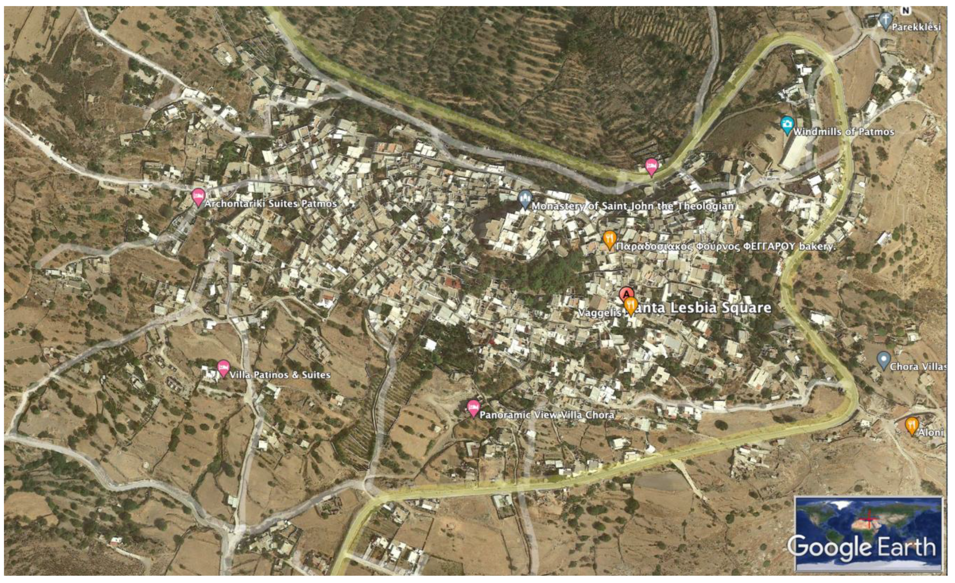
The island has significant religious value, as it is believed that Saint John the Theologian wrote both his Gospel and the Apocalypse there and, as a result, a synonymous monastery dedicated to the disciple was founded in 1088 and has been a place of pilgrimage ever since (Figure 2). Right below the monastery, which sits on top of a hill, the old settlement of Chorá associated with it encloses many religious and urban buildings. According to UNESCO’s website, “it is one of the best preserved and oldest of the Aegean Chorá”. Below the monastery lies Santa Lesbia Square, which is close to the urban house presented in the case study in this paper.
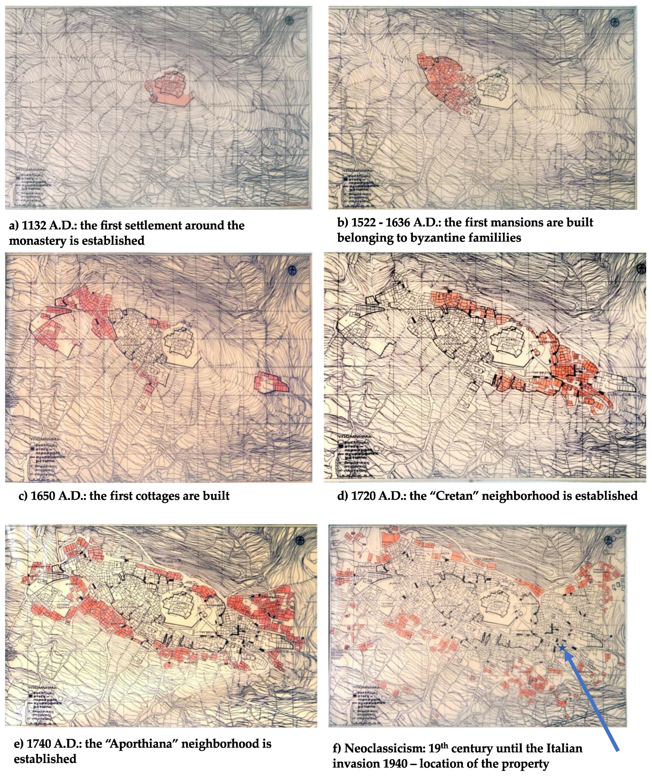
The Outstanding Universal Value of this UNESCO entry is also based on the fact that it comprises one of the few settlements in Greece that have evolved uninterruptedly since the 12th century. According to research carried out by Iakovidis [3] and presented in a self-published book that is out-of-print and can only be found in the National Library, the following historical events have shaped the patrimonial heritage of the entirety of Chorá:
  • In AD 1132, the first settlement around the monastery was established in a formation that favored the protection of the population (Figure 3a);
  • After the destruction of the Byzantine Empire by the Turks in AD 1453, 100 Byzantine families established the settlement Alotina and, between AD 1522 and AD 1636, the first mansions were also built (Figure 3b);
  • In AD 1650, the first cottages were built (Figure 3c);
  • In AD 1720, the Cretan neighborhood was established by Cretan refugees after the fall of Handakas Port (in current Heraklion) to the Turks (Figure 3d);
  • In AD 1740, the Aporthiana neighborhood was established, signaling a significant change in Chorá, since a northern triangular area was created. Notably, “Aporthiana” etymologically means “outside of the doors” (Figure 3e);
  • During the 19th century, the settlement expanded in the South (Figure 3f).
Given that there are only a few other places in the world where religious ceremonies that date back to early Christian times are still practiced unchanged, its value for Orthodox Christianity is inestimable.
Chorá is protected by the provisions of Archaeological Law 3028/2002 “On the Protection of Antiquities and Cultural Heritage in General” and by a number of ministerial decrees published in the Official Government Gazette. All restoration proposals for governmental or privately owned properties must be submitted at the regional service (Ephorate of Antiquities of the Dodecanese). After thorough checks, the entire study is transmitted to the Directorate for the Restoration of Byzantine and Post-Byzantine Monuments for further checks and, finally, it is introduced to the Central Archaeological Council of Greece (CAC). The Council’s history, composition and role are described elsewhere [2]; however, it is crucial for the approval of any proposal in UNESCO protected areas.
Greek legislation regarding conservation strategies in such protected areas—and especially, remote islands—takes into consideration the fact that these areas are inhabited by people and been throughout their history. Time, wars and financial difficulties have certainly left their mark on buildings, but, nevertheless, permanent residents of these islands are encouraged to stay to avoid abandonment and further deterioration on an urban scale. At the same time, due to the high historical value of particular settlements, only conservative approaches are allowed, even in privately owned properties, and the Central Archaeological Council of Greece safeguards related policies and laws.
Moreover, heritage buildings have always been and will continue to be subject to interactions with their natural environment. Climate change is an additional potential threat, as it exacerbates the expected rates of decay and contributes to the acceleration of the deterioration process. Over the second half of the 20th century, climate change has greatly affected conservation strategies and the need to adapt to climate change has become increasingly apparent, a fact that has affected design considerations in this study.

2. Approaches to Heritage Conservation and Current Research

2.1. Environmental and Climatic Considerations for the Conservation of Patmian Urban Houses

Sustainability concerns have had a central role over the last 50 years and, indeed, have positioned themselves at the center of the debate regarding conservation methodology. In the global context of increasing pollution, climate change, and the growth of the tourism industry, the above concerns are becoming even more important, as their negative effects can be felt and seen on monuments even by ordinary people and even on remote Greek islands in the Aegean Sea.
UNESCO’s Recommendation on the Historic Urban Landscape reflects the global concern to reach an equilibrium that takes into consideration historical, cultural, ecological, and social aspects. Therefore, legislation adopted by Greek governments aims at avoiding the transformation of cities and cultural centers into “open air museums” and ensuring that the living sustainable “historic center” approach prevails.
In the above context, climate change has proven to be an increasingly difficult challenge while planning building conservation on small Greek islands. Heritage buildings in this region generally suffer from accelerated deterioration due to changing weather patterns, in addition to destructive forces such as earthquakes, which used to represent the sole enemy of cultural heritage architecture in the past.
On the island of Patmos, monuments suffer from various natural factors; for example:
  • Intense winter winds;
  • Strong summer sunlight exposure;
  • Fluctuations in temperature and heating–cooling cycles with temperature differences ranging way over 15 °C in 24 h in autumn;
  • Salt crystallization cycles and increased relative humidity;
  • Electrochemical factors;
  • Biological factors;
  • Seismic activity.
All of the above result in accelerated effects on masonry of the type found in Patmos, especially when clay-based mortars are used.

2.2. Reuse versus Adaptive Reuse for the Conservation of Patmian Urban Houses

Internationally, reuse of heritage buildings is regarded as a sustainable option offering a twofold advantage: (i) the production of demolition waste is avoided and the use of new materials is limited, and there are also reductions in transport, energy consumption and pollution since the lifespans of structures are prolonged [4]; and (ii) the preservation of collapsed or ruined buildings instead of their restoration/reconstruction can potentially lead to the formation of abandoned areas resembling open air museums. Reuse of heritage buildings offers significant environmental benefits in terms of energy savings, lowering the carbon footprint of structures and reducing life-cycle costs, as substantial amounts of building materials can be reused in an effort to maintain the originality of the structure. At the same time, it offers social and economic advantages [5] and fosters the achievement of circular economy goals [6]. Studies on various components of sustainable development with regard to the reuse of historic structures have identified four key elements; social, economic, environmental and political–institutional elements [5]. The economic and environmental advantages have already been discussed. With respect to the latter, while Greek legislation forbids the construction of new buildings on empty land plots, it does in fact encourage the restoration of existing ones, no matter their architectural preservation status. Restoration is undertaken by means of both conservation of non-collapsed parts of buildings and reconstruction of the remaining collapsed parts, so that a closed shell is created and the building can be inhabited, used and protected while, at the same time, architectural form is controlled and preserved on the larger urban scale.
With respect to the social advantages, this approach also holds strong anthropocentric value, since the urbanization of remote islands (instead of the accumulation of large populations in the capital, Athens, and other major Greek cities) is encouraged for individuals who own property, even if it is in a partially collapsed state. Along with tangible values, intangible values are also enriched, since the social aspect is enhanced by bringing more inhabitants back to the remote islands. Urban regeneration and increased attractiveness are key issues in the social and economic prosperity of remote islands.
Reuse of historic structures and areas is directed by a number of different strategies in the field of urban preservation in an effort to control overtourism, which brings excessive pressure to historic areas and undoubtedly governs the main economic activities in the respective historic centers [7,8,9]. A number of successful and less successful (due to lack of infield research) examples of large reuse projects can be found in literature [10].
Some researchers also suggest “adaptive reuse” for even more pronounced social benefits. The term can be broadly defined as “any building work and intervention to change its capacity, function or performance to adjust, reuse or upgrade a building to suit new conditions or requirements” [11]. This approach is rooted in the 1800s, with Eugene Emmanuel Viollet-le-Duc (1814–1879) recognizing it functions as a way to preserve historic structures. Significant scientific arguments have been presented since the 1800s, with some scholars objecting to the main principles and others expanding on various theoretical approaches [12,13]. A thorough discussion of the key 19th and 20th century conservation theories on contemporary adaptive reuse of heritage buildings has been published by Mehr [14] and various opposing theories have also been presented [10]; however, these lie beyond the scope of the present paper.
A significant number of examples of adaptive reuse can be found in the literature. Typically, adaptive reuse case studies particularly stick to changes in uses. Two of the following examples are UNESCO-related, whereas the third example refers to an area near an ancient Greek city:
  • In Hong Kong, the Bethanie Chapel built in 1875 as a sanatorium by the Paris Foreign Missions Society has been transformed into the Academy for Performing Arts and reopened in 2006. At the 2008 UNESCO Asia-Pacific Cultural Heritage Awards, the project received an Honourable Mention in recognition of the efforts made for its successful restoration and conservation [5];
  • Again in Hong Kong, the Central Ordinance Munitions Depot, a military facility for storing arms and munitions during the Sino-Japanese War, was built by the British Royal Engineers in 1937 and has been transformed into a clubhouse. This project, which started with the submission of a proposal in 2002, received the Award of Merit by UNESCO in 2007 [5];
  • The small village of Umm Qais in Jordan, near the ruins of the ancient Greek city of Gadara, comprised of urban houses, was acquired by the Ministry of Tourism and Antiquities of Jordan and was converted into a multi-functional village with cafeterias, restaurants, a library, etc. [15].
The list of heritage buildings that have undergone “adaptive reuse” around the globe is indeed very long. In Europe, such projects have been studied from a number of viewpoints, such as the construction challenges of adaptive reuse of the following four structures: (i) the Musee d’Orsay, Paris, 1986; (ii) the Tate Modern Museum, London, 2000; (iii) the Alter Hof, Munich, 2005; and (iv) the Maritim Hotel Erlweinspeicher, Dresden, 2005 [16]. More factors affecting the adaptive reuse of 16 abandoned or disused European heritage structures are discussed in the literature [17].
However, in the case of privately-owned urban houses, the original use of the building can technically be maintained, and, in these cases, the Greek Central Archeological Council [2] favors such an option, advising that, in fact, the restoration designs should aim at maintaining the particular uses of the various spaces of the houses where possible. At the same time, when maintaining the use of a structure, the conflict with the local community that can occur in “adaptive reuse” cases is avoided [18,19], as is the need to determine new urban forms [20] or acquire additional permissions for the new uses [21,22], while the continuity of local community life is encouraged [23]. Lastly, particularly in the case of UNESCO protected areas and structures, only very conservative approaches are allowed by the Greek government. For this reason, we based our design on the “reuse” strategy, which we deploy and explain extensively in the following sections of the paper.
The current paper is structured as follows:
  • The site is presented through the analysis of the typology and morphology of Patmian urban houses in order to assign it to a specific category. A thorough description is offered using a number of architectural drawings, the various construction phases are explained and the documentation of the urban house is presented. Each area of the two floors is individually described in greater detail in order to define the exact uses, which will be maintained in the “proposal” design;
  • The pathology of the structure and deterioration due to environmental attacks are presented through selected photographs and related discussion;
  • A discussion on the reversal of the pathology by merging the architectural, structural and mechanical engineering design requirements together with the strict restoration principles is offered;
  • The proposal for the restoration of the site, using architectural and structural drawings that were submitted to and approved by the Central Archeological Council of Greece, is discussed;
  • Concluding remarks are provided.

3. Current Condition of the Urban House

The building is one of many found today in dilapidated condition in Chorá on the island of Patmos. It is located in the center of the settlement, southeast of the monastery of Saint John the Theologian, and it has a total plan area of 91.84 m2. It should be noted that it is privately owned.
Although the original design has not been extensively altered during the lifespan of the building, many later additions have taken a toll on its original form.

3.1. Typology and Morphology of Patmian Urban Houses

The building materials that were historically used on the island were those that could be locally sourced, excluding timber, which was scarce.
Two stone types are available on the island: granite-based stones and limestone. Granite-based stones were initially used for masonry walls, but they were rarely used in subsequent years as they were difficult to process and cut into preferred shapes, instead being mainly used as corner stones.
The mortars used were mainly pozzolanic. When water-proofing was needed, the formulations typically included volcanic ash, brick dust and local sand mixed with lime and water. For stone mortar and plastering, quartz sand or pumice ash was used instead. Wood was used for doors and windows and timber for flooring members.
Residential buildings on the island of Patmos developed around the rectangular single-room house type. The oblong-shaped space had two functional sub-spaces, one for common house work and living and one that functioned as sleeping quarters. The entrance opened to the internal garden, where a cistern and a kiln could be found.
On the narrow sides, window openings were positioned towards the internal garden to properly light the internal spaces. Openings in the sleeping spaces and the longer sides were not very common.
The further development of the above-mentioned house type gave way to the two-level Patmian house type, a typology that is mostly observed in the Chorá settlement. In its simplest form, the kiln area was covered, leaving the rest of the internal garden exposed, in which a staircase that led to the second level was placed, forming a semi-exposed space above the kiln. The sleeping space was moved to the upper floor, leaving the ground floor to be used as a multi-purpose space or for storage.
The placement of the second level created additional needs for ground floor lighting and ventilation, leading to the creation of the high-positioned traditional windows found in most houses in Chorá.
The openings caused a security concern and, when the shutters were closed, the light and ventilation provided were minimal. The shutters consisted of solid wood and opened towards the interior of the house. Later on, when glass windows were introduced, solid shutters were less often used.
Timber members supporting the roofing were mostly cypress trunks to make covering of long spans feasible. Smaller members were placed above them in the opposite direction, on top of which canes were attached by means of a seaweed and soil/clay mixture.
Floors followed the same construction technique, substituting clay with wooden boards or ceramic tiles.
The garden and the ground floor spaces were covered with ceramic tiles in various sizes (Patmian tiles).

3.2. General Description, Construction Phases and Documentation of the Current Urban House

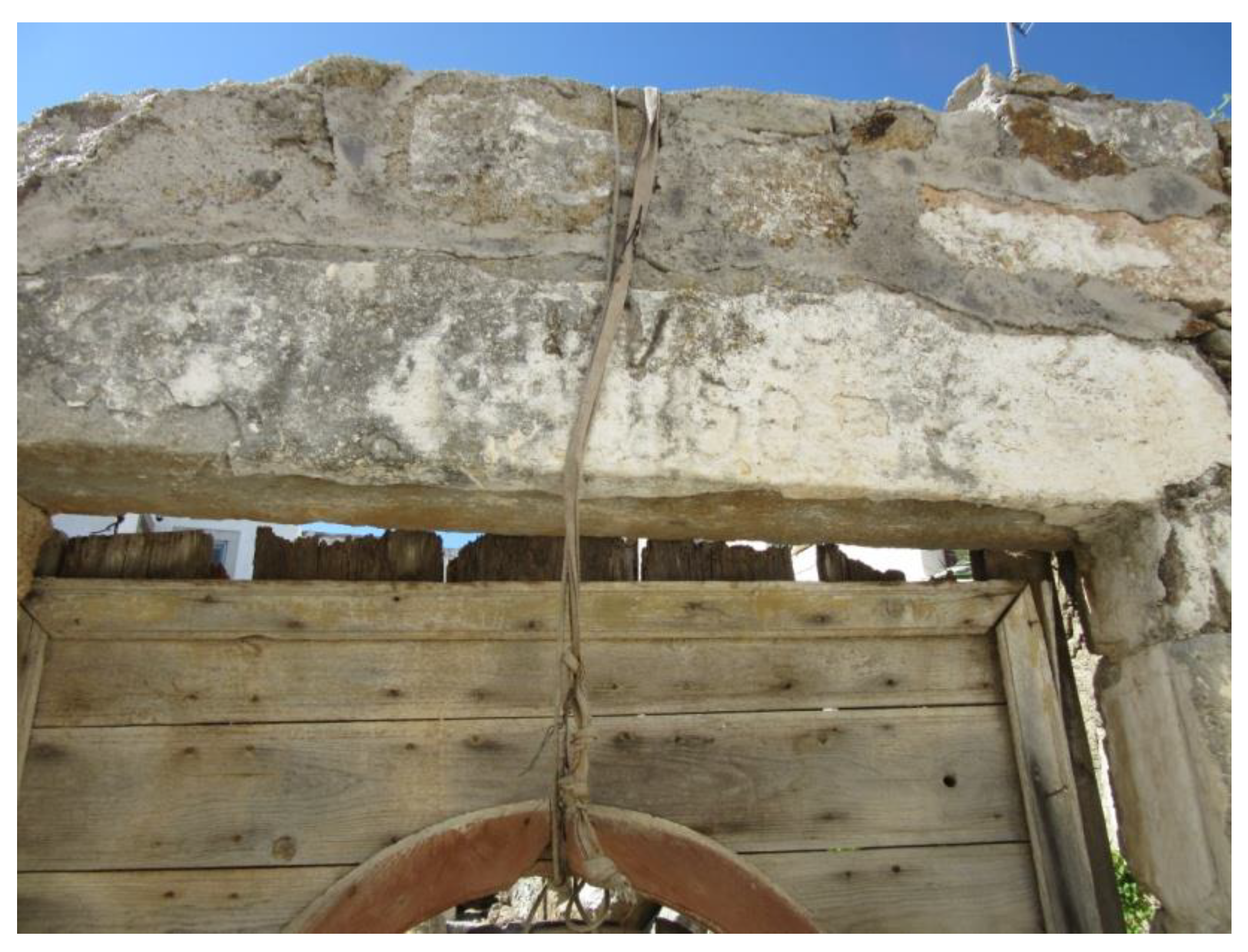
The inscribed date of 1850 (Figure 4) found on the lintel of the main entrance most probably corresponds to the original construction date of the house. The house features some later-dated additions, but there is no evidence of extended reconstruction in the past.
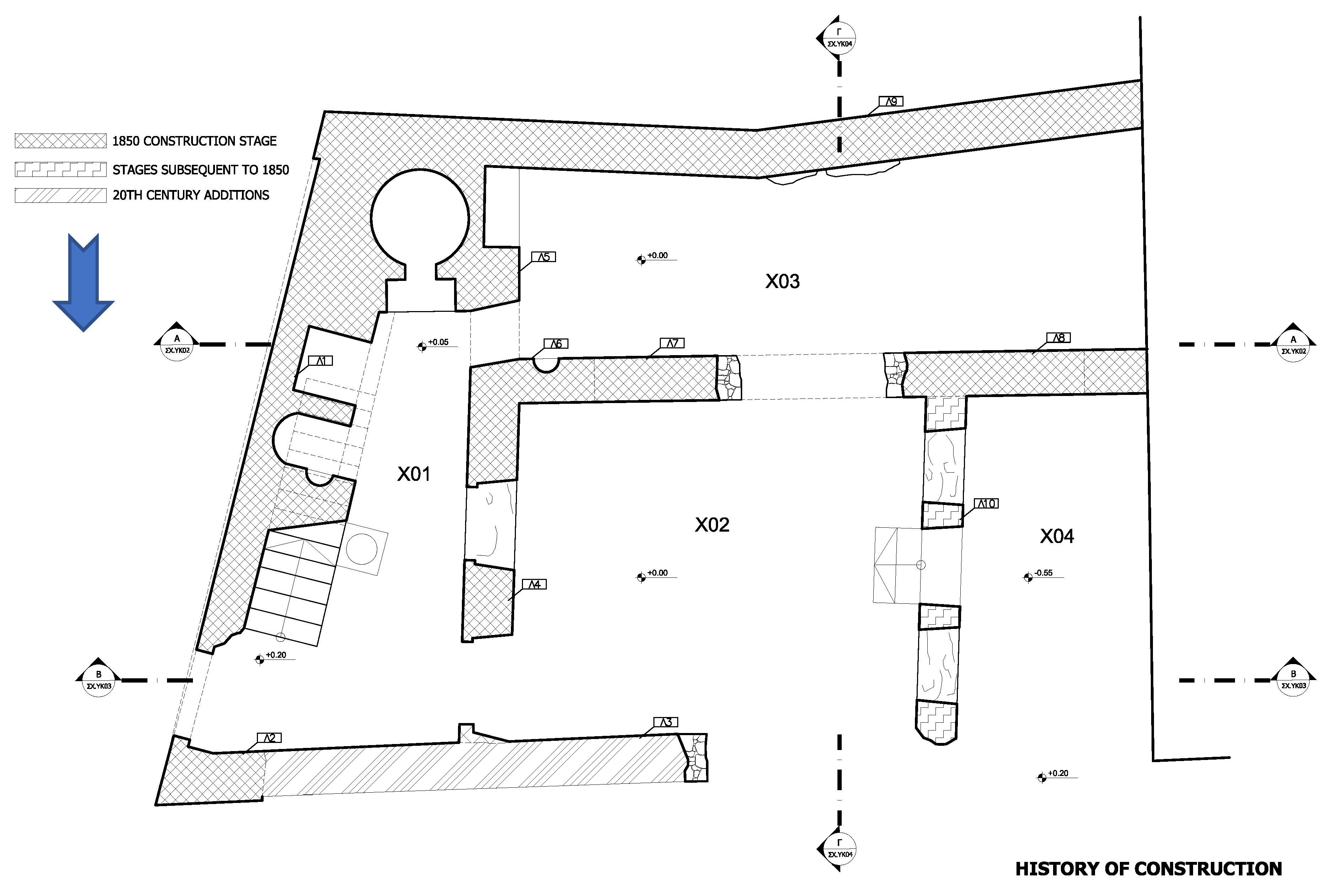
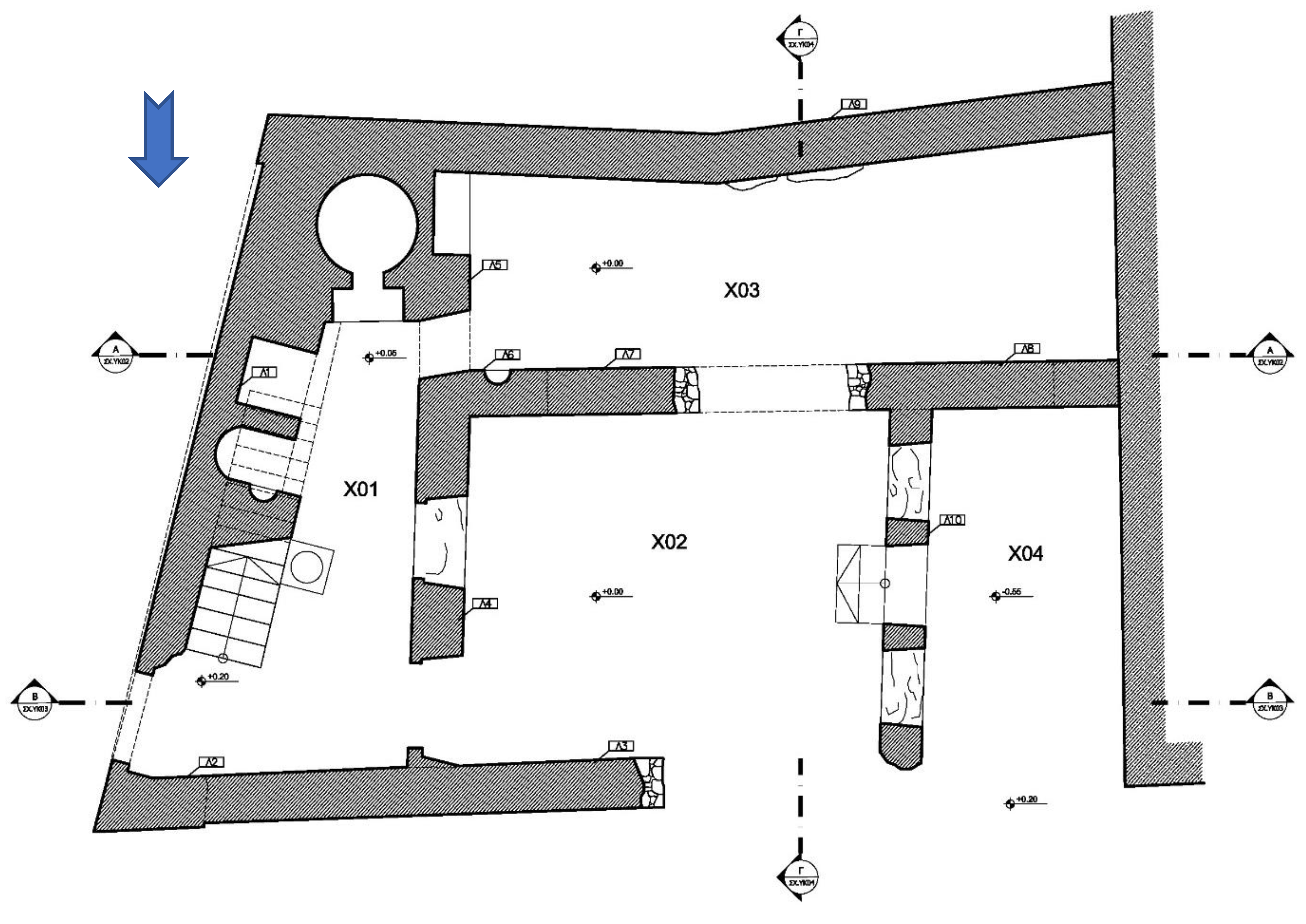
The house belongs to the two-level Patmian house-type architecture, with all its spaces following the hierarchy of this building type. The entrance opens to the internal garden, as shown in Figure 5 (space X01), where a cistern and a staircase that leads to the second level are located. On the eastern side, the covered part of the internal garden can be found, which includes a kiln and a fireplace. An enclosed space that is separated from the rest of the house by an arch can also be found on the lower level (spaces X02 and X04). The living space and the bedroom were located on the upper level. A short opening also connects the kiln area with space X03.
In subsequent years, a separating wall was constructed to create a second internal garden (space X04); the central arch was partially blocked, probably to prevent structural deterioration; and an opening was placed in the middle between spaces X02 and X03 (Figure 5).
All spaces on the ground floor are on the same level, with space X04 being the sole exception. The upper level was 3.15 m higher.
The original mortar used, parts of which can be found all across the building’s masonry, is clay-based. The interior plastering has not survived, except under the external staircase where a sink was probably placed, so the plaster is made of hydraulic lime. The same plaster was used to waterproof the cistern.
External plaster can be found on the eastern elevation and consists of a thin layer of lime.
In November 2018, soil and vegetation were removed and the internal spaces were excavated, bringing to the surface most of the architectural elements that were buried after its collapse. The architectural plan was almost clear and consisted of the areas described below.

3.2.1. Space X01, the Internal Garden

The internal garden is on the eastern side. The entrance opens to the garden, where a cistern and a 14 step staircase that leads to the second level are placed (Figure 6). The covered part of the garden is located further south, which includes a kiln and a fireplace.
The stair is supported by a vault where, judging by the plaster that can be seen today, a sink was probably placed.
The chimneys for both the kiln and the fireplace end up in a common path ending at the eastern elevation.
On the west side, traces of an old, small window opening of 0.92 m in width can be seen opening towards space X02, as well as a narrow, short door opening of 1.60 m on the far south of the same wall, opening towards space X03 and bearing a wooden lintel (Figure 6).
The main entrance on the eastern elevation bears a monolithic stone lintel, which has a width of 1.12 m and a height of 2.16 m and, on the exterior sides, an inscription with the year 1850 is visible (Figure 4), probably the date of the initial construction.
The construction is mostly uncoursed rubble masonry, except the northeastern corner stones, which are rectangular and coursed.
The arch supporting the vault underneath the staircase is made up of nine stones, while, on the arches of the kiln and fireplace, bricks were used. Bricks were also used for local repairs of the masonry.
The northern masonry wall was constructed using rectangular and mostly coursed masonry, with three corbels remaining today 2.11 m above pavement level. They protrude 0.15 m from the masonry and indicate that the second level had a small overhang over the ground floor.
Above the kiln, traces of the timber construction of the second floor are still visible today.

3.2.2. Space X02, the Main Space

This was the main space (Figure 7). On the southern part, a large arch with a span of 6.18 m and a height of 2.7 m was constructed dividing the space into two. Thirty-seven (37) stones make up the arch that supports the loads of the second level. The arch was partially blocked using rubble stones in subsequent years.
On the eastern side, a 0.62 m wide wall was constructed, where traces of two 1.14 m wide window openings and a 1.25 m wide door opening can be found. The wall was a later addition that reduced the area of the main space and introduced a second garden in the west side.
The northern masonry wall of space X02 was constructed with dry rubble masonry in contrast to the rectangular and coursed masonry of the northeastern corner. This part was constructed in recent years to act as a retaining wall for the collapsed building material.
On the west, three steps leading to space X04 can be found.

3.2.3. Space X03

On the northern side of the space, which is located in the south of the building, the above-mentioned arch that separates it from space X02 can be found, while, on the southern side, the masonry is shared with the neighboring collapsed house, though today it retains the soil and stones on the opposite side. Part of the wall is based on a large rock formation (Figure 6). On top of the wall, small square cavities that supported the timber construction can be found.
The narrow door opening towards space X01 is located on the eastern side, while further south the high-positioned 1 m wide traditional window was constructed to act as ventilation shaft connected to the second level window, which also provided natural light to this dark space on the ground level.
On the western side, the reinforced concrete wall of the neighboring contemporary building can be seen today.
On the northeastern side of the space, traces of Patmian ceramic tiles can be found.

3.2.4. Space X04, the Second Garden

The floor level in this space is 0.55 m lower than the rest of the house. It was created in subsequent years after the original construction, following the partial block of the main arch between spaces X01 and X02. It was created through the construction of a wall in space X02. Its purpose was to create a second garden in the western side (Figure 6).
On its west side, the space ends with the reinforced concrete wall of the neighboring contemporary building.

3.2.5. Northern Elevation

The northern elevation has mostly been destroyed. In its place, a masonry wall was recently constructed from dry (without any mortar) rubble masonry, which acts as a retaining wall for the collapsed building material (Figure 7).
The only original part of this elevation is the northeastern corner, constructed using the rectangular and coursed masonry up to a height of 2.70 m, while 2.35 m above pavement level, the three remaining corbels that supported the second level are still in their original positions.

3.2.6. Eastern Elevation

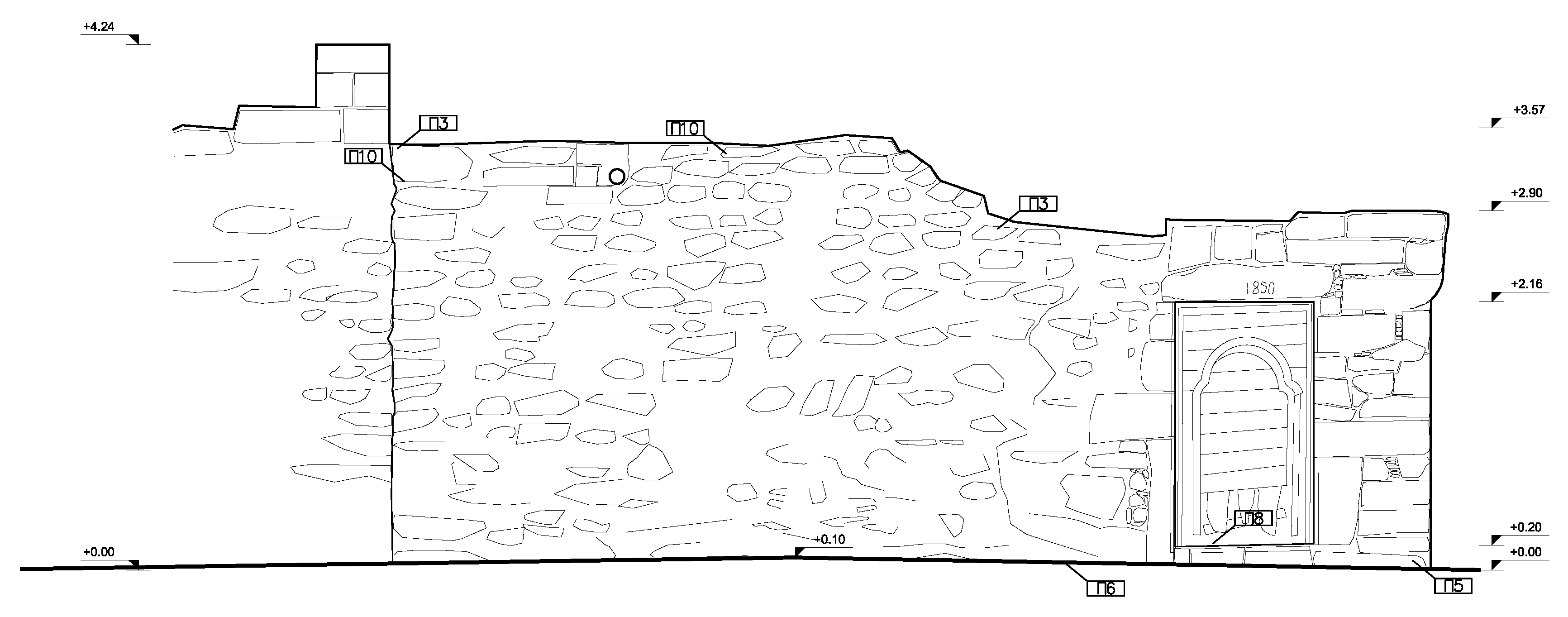
The eastern elevation, in contrast to the northern one, remains mostly intact. It reaches a height of 3.57 m above street level (Figure 8).
The main entrance door opening is located on the northern side of the elevation at a height of 2.16 m. The wooden door is also preserved, although in a deteriorated condition, but its form and design are perfectly visible.
The chimneys of the kiln and the fireplace open onto the elevation, which is constructed using rubble masonry, except for the northeastern corner.

3.3. Pathology of the Structure

The urban house is currently in ruins. The entire second floor has collapsed and, among the external walls, only the eastern (masonry wall labeled Λ1 and Λ2 in Figure 5) and southern (masonry wall labeled Λ9 in Figure 5) ones are the originals, both showing significant permanent deformations and rotations from the vertical positions. Of the internal original walls belonging to the first construction phase of the structure, those labeled Λ3 (also shown in Figure 9a) and Λ4, Λ5, Λ6 and Λ7 (photos of which are shown in Figure 9d) in Figure 5 are also in a very bad condition.
As shown in Figure 9b, the contemporary external masonry wall on the northern side of the house was built dry without mortar to act as a retaining structure for the demolition waste in the interior of the house. In subsequent years after the initial construction, a separating wall was constructed to create a second internal garden (Figure 9c). At the beginning of the 19th century, the central arch was partially blocked (Figure 9d), probably to prevent structural deterioration, and a door opening was placed in the middle.
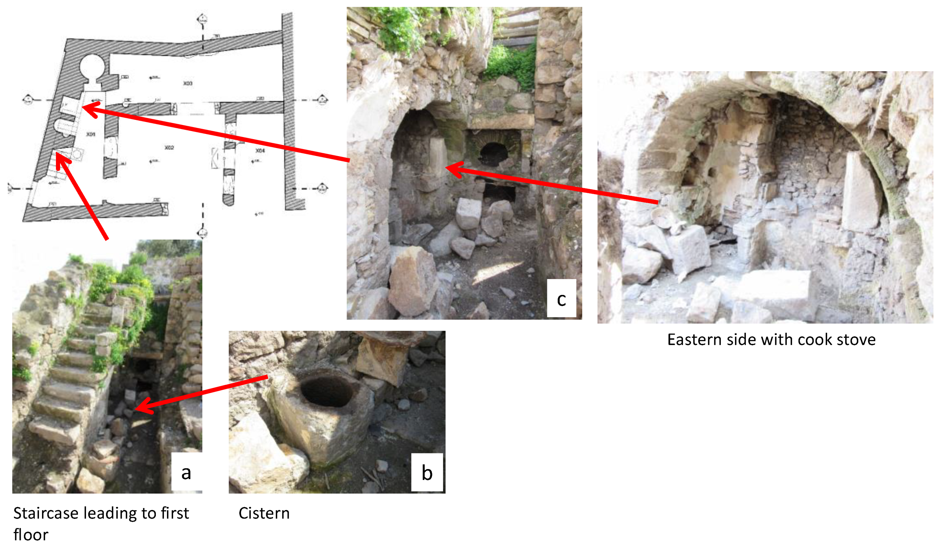
It has already been stated that the building belongs to the two-level Patmian house-type architecture. The entrance opens to the internal garden, where a staircase leading to the second level (Figure 10a) and a cistern (Figure 10b) are placed. The side wall of the staircase has rotated by approximately 10 degrees from its original vertical position.
On the eastern side, a covered internal garden can be found, which includes a kiln and a fireplace (Figure 10c). An enclosed space separated from the rest of the house by an arch can also be found on the lower level. The living space and the bedrooms were located on the upper level.
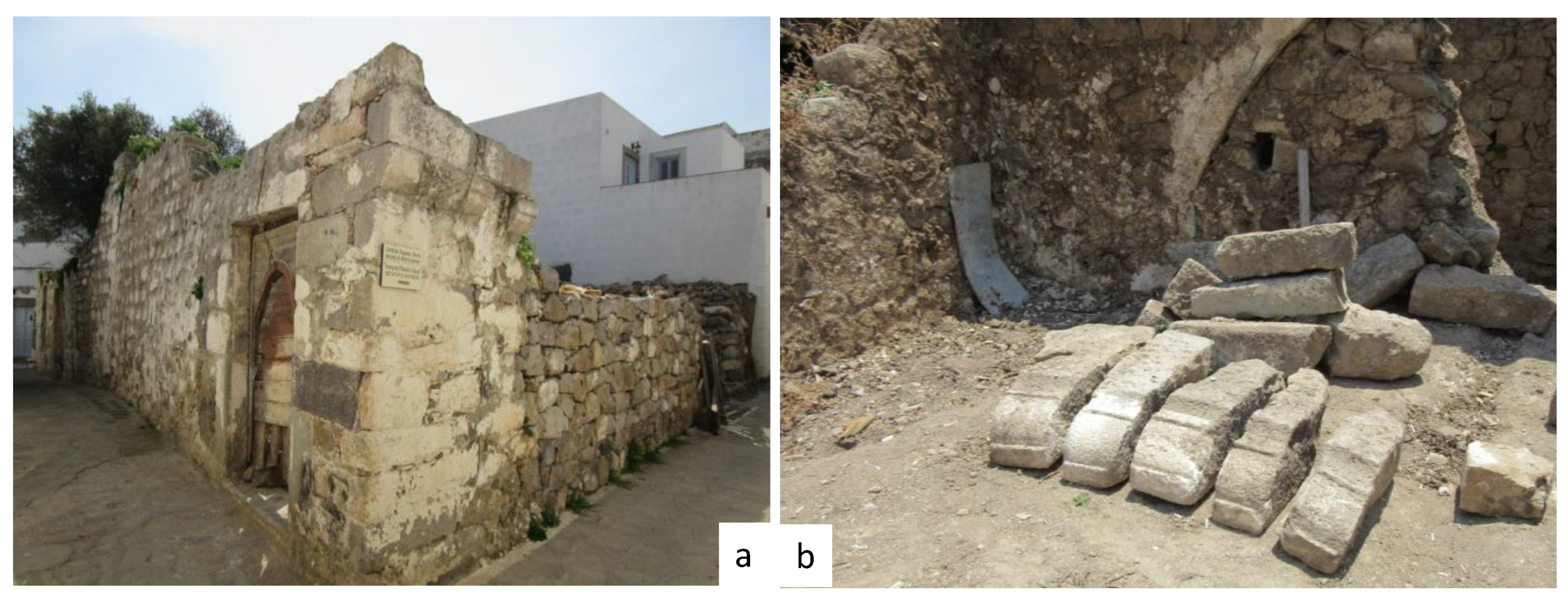
On the northern elevation, three stone corbels can be found (Figure 11a), proof of the long-lost terrace on the upper level. They extend 15 cm from the masonry edges to create a larger space above. During excavations, five more similar corbels were unearthed, in addition to a number of squared and semi-squared corner stones (Figure 11b).
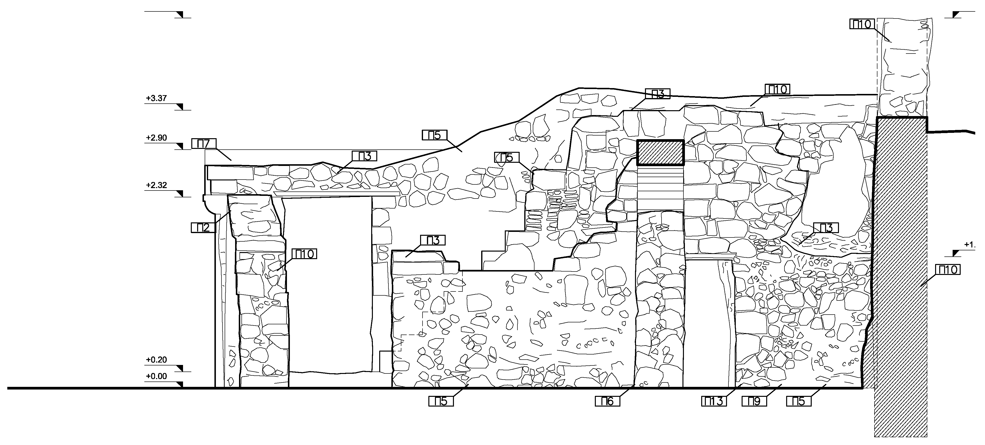
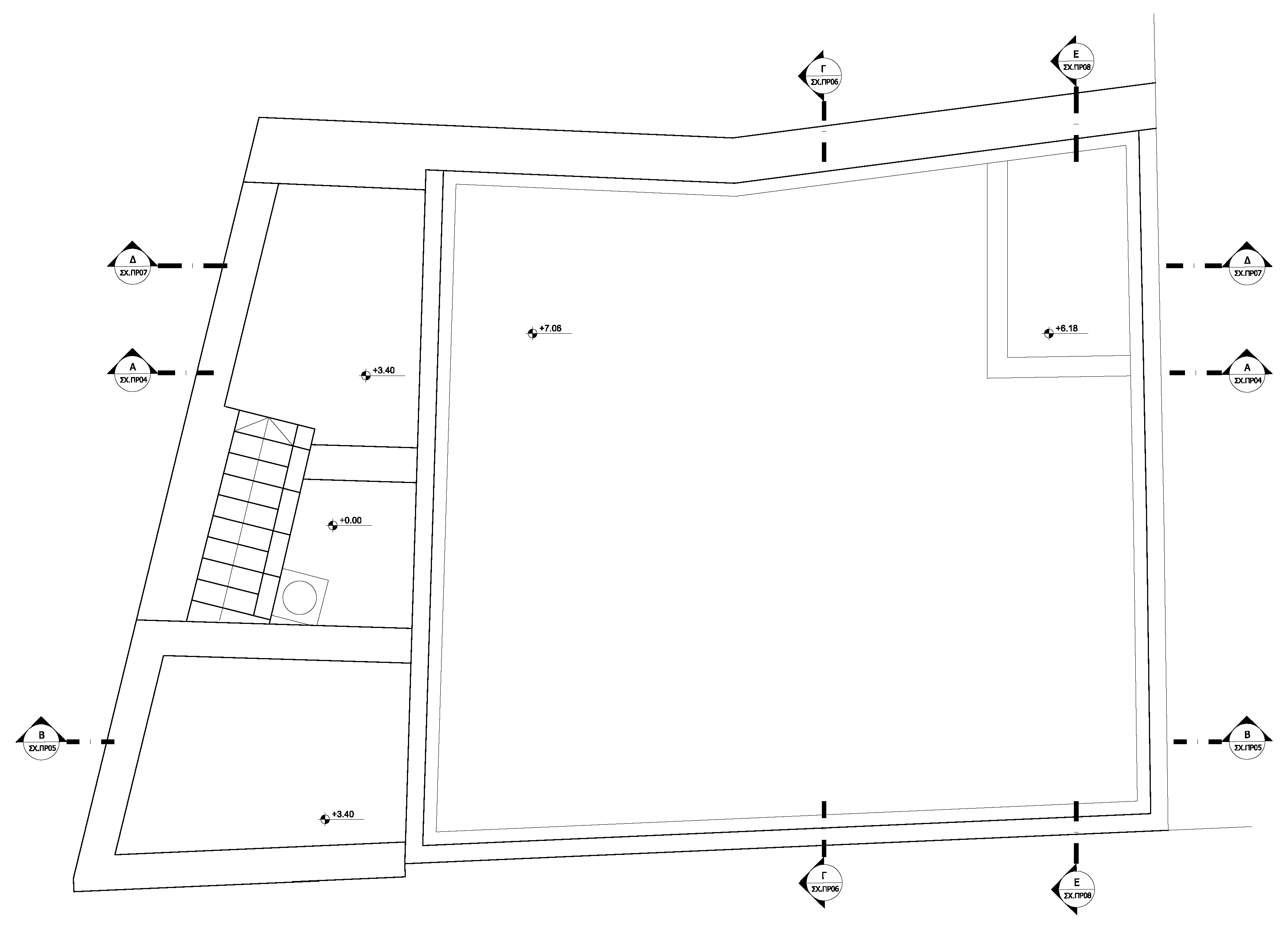
In the two section drawings below, the inclination of the eastern external wall is evident (Figure 12), as well as that of the southern external wall (Figure 13).
As expected, due to the seismic activity in the region, extensive cracking can be witnessed in all remaining exterior and interior masonry walls.

4. Discussion on the Merging of Architectural, Structural and Mechanical Engineering Requirements

Taking into consideration the Venice Charter for the Conservation and Restoration of Monuments and Sites [24], along with all contemporary theories and charters on conservation and restoration of monuments, the basic principles of the design aimed to:
  • Sustain and improve the original historic elements of the building;
  • Utilize traditional building techniques while improving them as required with the use of contemporary materials;
  • Target the highest possible reversibility and the use of high-strength materials that are also compatible with existing materials;
  • Avoid the loss or destruction of original material that holds historic evidence while reusing as much as possible of the original salvaged materials and structural elements;
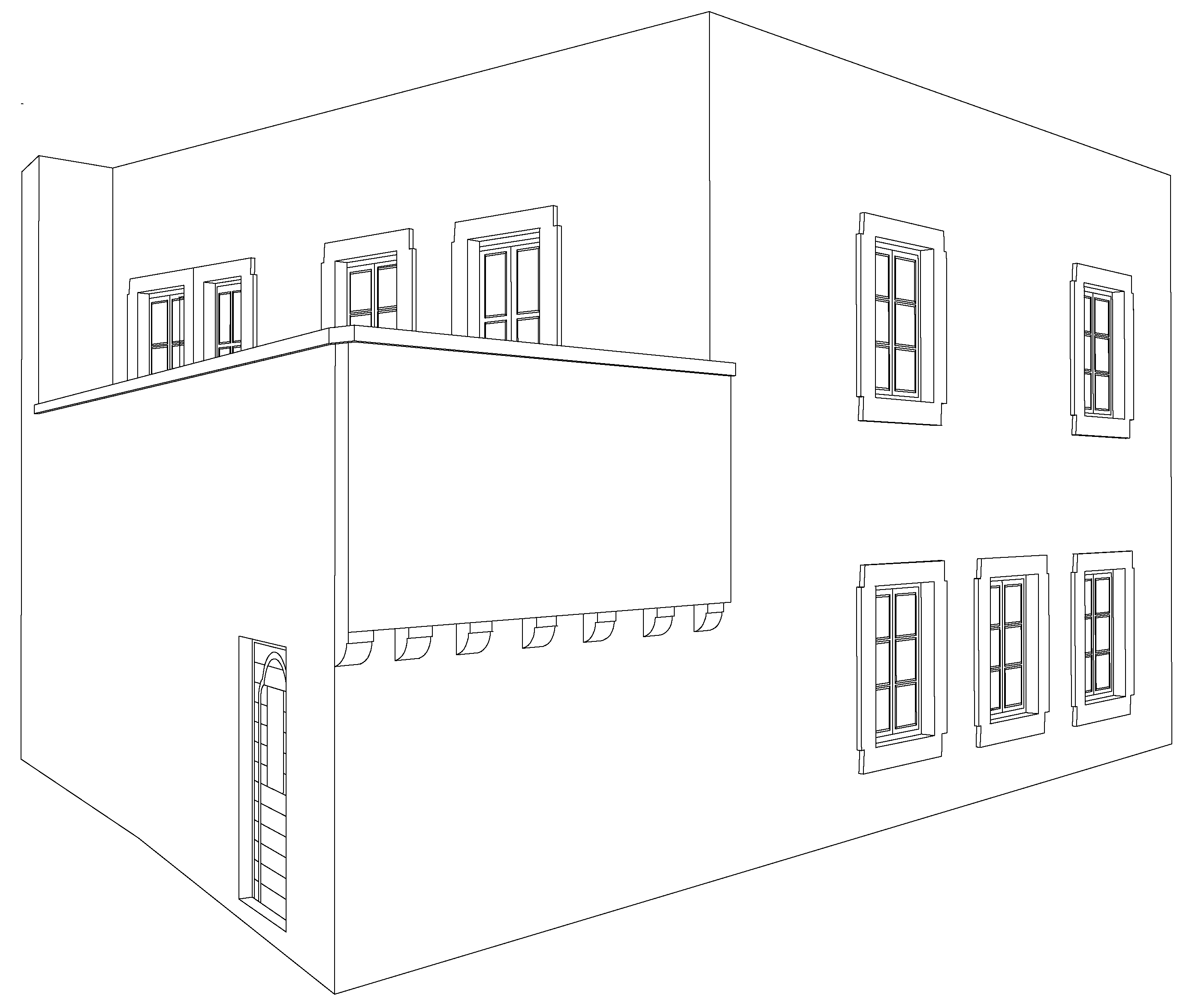
  • Restore the building to its 19th century form (Figure 14), with conservation and restoration of the ground level to its current morphology and reconstruction of the collapsed first level.
The building is recognized as a part of a historic organic unity and plays a significant role as a connecting element and an irreplaceable unit of the historic center of Chorá on Patmos. The shell and layout of the floors can be proven to represent the characteristic typology of the urban houses in Chorá, as extensively discussed in Section 3.1 of this paper.
Following the “triple R” approach for restoration proposals proposed by ICOMOS [24], it was decided that the restoration proposal should be:
  • Recognizable (the reconstruction easily restores original features from the original);
  • Respectful (the reconstruction is as similar as possible to the original);
  • Reversible to the greatest extent possible [25].
In other words, all the interventions were aimed at respecting the morphological, functional and structural characteristics of this type of structure.
Ensuring continuity, integrity and durability with respect to original architectural features was considered imperative in the Amsterdam Meeting in 1998 [26]. Furthermore, the concept of “management of change”, as described in the Charter of Krakow, has been developed into the “management of continuity and change” by scholars and restoration specialists [26], stressing the importance of the preservation of continuity in historical sites and areas [27]. Following this concept, it was decided to maintain the exact uses of each distinct space, as described in Section 3.1. Furthermore, the exact number of openings was also maintained, the exact floor height was adopted and building techniques that would be closer to the traditional techniques were taken into consideration.
However, five specific characteristics limited the available restoration strategies:
  • The very bad condition of the two remaining external walls (Λ1 and Λ9);
  • The collapse of the second floor;
  • The need to design the intermediate level with timber, following the traditional construction techniques;
  • The high seismicity of the island, which has a peak ground acceleration (PGA) of agR = 0.16 g [28];
  • The proximity to a modern house with a reinforced concrete frame to the west.
Restoring the ground floor and reconstructing the first floor with all external walls made of masonry was the first scenario considered. However, preliminary analyses showed that the response of the structure under high seismicity and the low behavior factor (also known as the q-factor) of 1.5 were, according to Eurocode 8 (EC8) [28], inadequate. Indeed, the displacements exceeded the allowable limit and the fact that the west wall of the restored structure would be in contact with an existing reinforced concrete wall of the adjacent property posed additional restrictions on displacements. Therefore, all walls would have to be strengthened if the structure were to pass the current design provisions.
However, following the “triple R” approach to restoration proposals described by ICOMOS [25] and due to the non-reversibility of both the following procedures over the entire area of the walls:
  • fibers or resins for the strengthening of walls were avoided—natural grouts were preferred instead, even though the mechanical properties offered were lower;
  • sprayed concrete (also known as shotcrete) for the strengthening of the walls was forbidden.
Therefore, and in order to make the reconstruction distinctive, the west wall, which would have no openings since it would be in touch with the neighboring building, was proposed to be designed and constructed with reinforced concrete. Tie beams of reinforced concrete running at the top of each floor lever would be connected to the reinforced concrete wall—as well as the roof of the new structure, which would also be built with reinforced concrete—together with the creation of a reinforced concrete raft foundation connected to the masonry foundations of the existing original walls from the first construction phase of the building. In this way, all earthquake design provisions would be satisfied and the new structure could maintain its originality. Moreover, structural members made of contemporary materials (reinforced concrete) would stand out, following the Venice Charter statement that “…any extra work which is indispensable must be distinct from the architectural composition and must bear a contemporary stamp” [24]. Details of the structural design are discussed in the following section.
Last, but not least, in terms of mechanical engineering-related requirements, the introduction of a contemporary heating, ventilation and air conditioning (HVAC) installation was imperative. However, it was desired that the external units, which would be placed best on the roof, should not be visible from street level. Given that it was decided that the roof would be made of reinforced concrete, the conditions would be satisfied by creating a split-level slab on the roof slab only for the area in which the units would be installed. Details on the positioning of the equipment are discussed in the following section.

5. Restoration and Reconstruction Design in Ultimate Preparation for Future Climate Scenarios

5.1. Design Verification Approach

As mentioned above, settlement construction activity in Chorá is controlled and monitored by Greek laws that in fact forbid any new construction, with the only exception being the conservation and restoration of existing buildings. Therefore, there are strict rules for the restoration of any structure enclosed within Chorá.
As most uninhabitable houses in Chorá date back to the 1800s, the majority are in a dilapidated and collapsed condition.
The above entails design solutions that include a combination of conservation of sustainable parts and reconstruction of missing or collapsed parts that should integrate harmoniously with the whole, taking into account the need for the use of modern techniques to improve the inadequate (by today’s standards) traditional ones for conservation and construction. This also includes the need for contemporary mechanical equipment and plumbing (MEP) solutions.

5.1.1. Architecture and Form

The type of the house is clearly identifiable from the remains of its ground floor plan. The external walls form a boundary that clearly indicates the architecture of the ground floor. The plan of the first floor also follows that of the ground floor, while the presence of an external staircase, together with the remaining corbels, gives a good idea of the original form of the split terraces.
The level heights are well-documented, as some of the timber members above the kiln have survived the collapse, giving exact measurements of the clear height of the ground level.
The clear height of the first floor follows that of the ground floor.

5.1.2. Openings

Ground floor opening positions and widths are also clearly identifiable, while the height and proportions can be derived from similar buildings that survive today. The form, position and size of the high-positioned traditional window are also evident.
The doors to the terraces are a logical conclusion, while the windows on the northern side can be derived from similar buildings as well.

5.1.3. Floors

The ground level floor and the intermediate floor were proposed to be placed at the exact level of the original building. The materials used for the restoration were the same as the ones originally used: ceramic tiles for the ground floor and wooden/timber for the intermediate floor. The only improvement was the sound insulation.
The construction of the roof followed a different approach, as it was impossible for the traditional seaweed approach to offer water/thermal insulation of contemporary standards and it would need constant and yearly conservation. A reinforced concrete slab was designed to provide the above while at the same time offering an enhanced structural design for the house.

5.1.4. Walls

Original masonry construction was respected both in dimensions and form, with the only exceptions being the construction of the reinforced concrete wall on the western side due to structural concerns, as discussed below, as well as tie beams. The internal partitioning of the first floor was proposed to be constructed with fully reversible dry walls.

5.2. Conservation Approach

Apart from the basic design principles, which were presented in the previous section, once the materials forming the shell of the structure were chosen, as previously discussed, the restoration proposal was focused on more detailed issues. The conservation work was proposed to included:
  • Deep cleaning of masonry to clear deteriorated grouting;
  • The partial removal of deteriorated masonry in the uppermost parts of the walls, such as masonry Λ9 and Λ1 (original construction-phase walls), and the removal of masonry Λ3 and Λ10, which were built at much later stages (Figure 5);
  • Structural strengthening of the foundation with the use of a reinforced concrete foundation beam;
  • The construction of a drainage system internally around the building to reduce ascending moisture;
  • The reuse of demolished material for conservation purposes for structurally strengthening masonry elements (Figure 15). Cracks will be repaired, depending on size, with grouting, stone stapling or localized removal of surrounding material and cleaning and re-introduction of fresh elements. Masonry will also be strengthened with the use of compatible injection grouting, as discussed in a later section of the paper;
  • The use of dry walls for the first floor plan would result in maximum reversibility while minimizing the weight on the underlying structure;
  • Maintenance of the external stone staircase and restoration to its original form, and an internal timber staircase will be constructed;
  • Construction of the intermediate floor with timber members according to the traditional, though enhanced, methodology. Double rockwool sound insulation will be used. The ground level floor will be made of Patmian ceramic tiles based on a reinforced concrete ground slab. The roof of the first level will consist of a reinforced concrete slab with a nonbearing underlying timber structure similar to the intermediate floor with additional water insulation;
  • The reconstruction of wooden windows and doors.

5.3. Detailed Description of Restoration Works

5.3.1. General Layout of Living Spaces

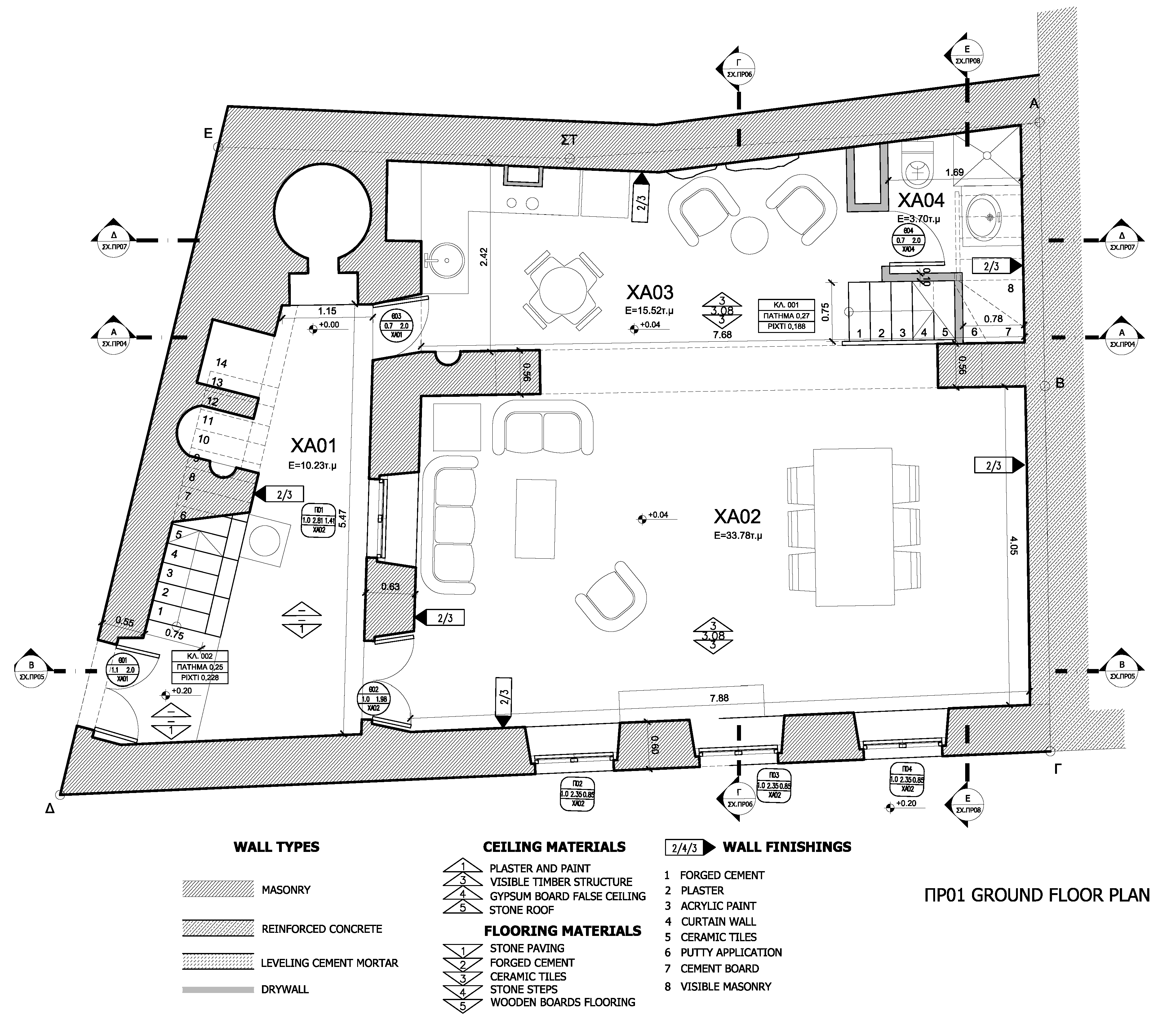
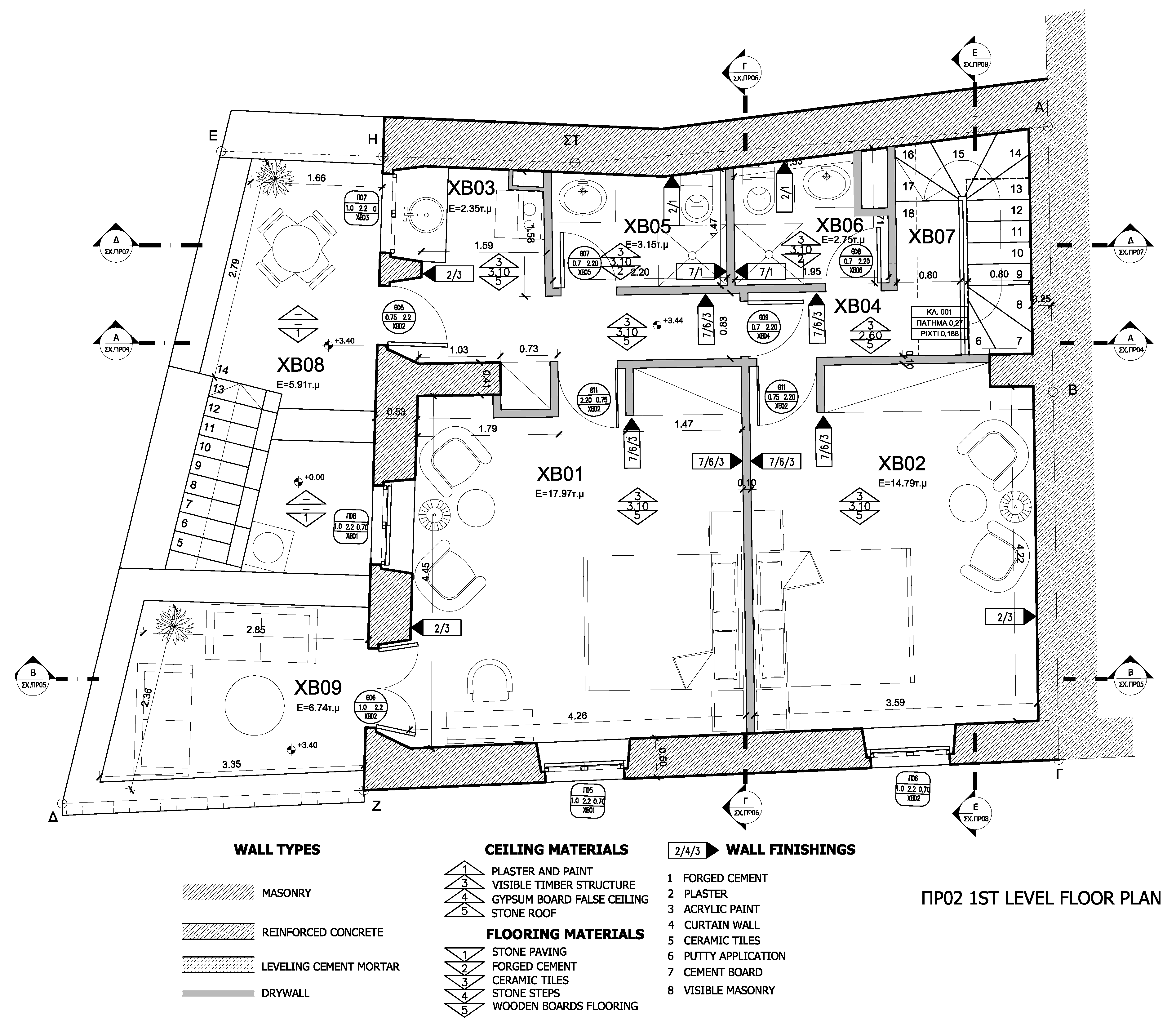
In Figure 16, all areas of the ground floor are denoted by the letters “XA” followed by a number, whereas, in Figure 15, all areas of the first floor are denoted by the letters “XB”, again followed by a number.
The original eastern entrance would be used again, leading to the internal garden (XA01 in Figure 16). The stone staircase, the kiln and the small arch will be restored. Stone replacement will take place only when absolutely needed, while priority will be given to existing fallen material. The stone staircase will be restored by removing the deviated members and restoring/replacing them as needed.
The living and dining room will be placed in space XA02 (Figure 16). Masonry part Λ3, which was constructed without mortar in recent years to act as a retaining wall for the collapsed building material, will be removed. Masonry part Λ2 (Figure 5), which is an extension of Λ3, belongs to the original construction phase and will be retained.
The contemporary kitchen will be located in the eastern part of space XA03 (Figure 16), while, in the western part, a timber staircase leading to the first level will be constructed. The stones that form the central arch will be numbered, dismembered and reconstructed with the exact same morphology using a temporary wooden frame.
The removal of the contemporary masonry Λ10 (Figure 5), perpendicular to the central arch, is justified, as it is a requirement for the arch’s morphological restoration, which also requires the clearing of the stones within the arch itself that block it.
Masonry Λ9 (Figure 5) constitutes the most deteriorated part of the building. It has severely deviated from straightness in all axes. Taking into consideration its current and future height and the loads it needs to sustain, which will also increase in the future as the masonry is shared between this house and the house next to it, the restoration of its geometry is essential. This will be implemented through the removal of the topmost stones to the degree needed, and the material removed will be reused/replaced accordingly. Strengthening of the masonry will follow with injection grouting/deep grouting. The structural strengthening of the foundation through the use of a reinforced concrete foundation level beam will have to be implemented prior to the restoration of the masonry walls.
On the first floor, two basic sleeping spaces will be created, XB01 and XB02 (Figure 17). Each space will have its own bathroom. Access to the first space will be provided by the external stone staircase in the internal garden through XB08, while access to the second will be provided by the internal timber staircase. A small kitchenette will also be placed in proximity to space XB01 to serve its needs.
As mentioned above, all internal partitions separating the various spaces on the first-floor level will be made of light plasterboard dividers with intermediate insulation with stone wool in order to maintain the reversibility of the intervention and minimize the deadloads imposed on the intermediate floor.

5.3.2. Construction Details for Floors and Roof

The construction details, including all materials used, can be seen in Figure 17. In detail, the architectural proposal included the following:
Intermediate floor
The intermediate floor will be based on 10 × 18 cm timber joists covered with 2 cm Swedish-type wooden boards. Double stonewool sound-proofing will be placed on top of the boards with intermediate wooden frames. Two-centimeter plywood will cover the frame and act as a base for the finished two-centimeter oak floorboards.
Ground level floor
The ground level floor will be covered with Patmian ceramic tiles on a 15 cm reinforced concrete ground floor slab lying on top of a 25–30 cm thick crushed stone layer. The crushed stone layer will be divided from the natural ground with the use of a thick nylon sheet.
First level roof
The roof of the first level will consist of a reinforced concrete slab with a nonbearing underlying timber structure similar to the intermediate floor, with additional 5 cm water insulation. In between the timber and concrete structure, a 4 cm thermal insulation layer will be placed.

5.3.3. Plastering and Coloring

The interior will be plastered with the use of cement-free lime-based pressed mortar. The exterior will be coated with water-based white emulsion paint (Figure 16).

5.3.4. Doors and Windows

New wooden windows and doors will be added. Double-glazed windows will be used while blue-gray colored shutters will be placed on the outer side (Figure 16).

5.3.5. Drainage

An internal drainage system will be constructed around the building to reduce ascending moisture. The trench will be covered initially with geotextile. A perimetric perforated PVC tube will be placed inside and the trench filled with gravel. Finally, a second layer of geotextile will protect the gravel, followed by the ground slab.

5.4. Structural Design—Material Considerations and Restrictions

The design aims to resolve the building’s severe structural problems by combining traditional and contemporary techniques. The existing structural system of retaining walls will be enhanced, and not replaced, by strengthening of the foundation, the partial removal of deteriorated, deviated and off-tolerance masonry and, finally, their strengthening with similar and compatible stones and application of deep (injection) grouting.

5.4.1. Masonry Walls and Other Elements

A large number of stones found inside the house during the excavation and cleaning works have been collected, as shown in Figure 15. The proposal envisages the re-use of this material after sorting for the construction of the damaged parts and those which are in poor condition. The format will be similar to that of the existing sections. Mortar will be used as a binder, compatible with the existing binder and according to the static study.
The maintenance of the existing stone structures will be carried out through the restoration of local damage, and their bearing capacity will be increased by repairing damage and cracks locally where they appear in the pathology plans using deep jointing and stone stapling. This will also be performed for local collapse, additions and reconstructions where it is considered necessary by the supervising engineer.
Walls will be reinforced with grout based on white Portland cement and hydraulic lime. The external masonry staircase will be restored and grouted as well.
Following EC-6 §3.6.1.2 [29], the characteristic compressive strength was taken as:
f k = K · f b 0.7 · f m 0.3
where K is a constant depending on the quality of masonry stones (EC6, table 3-3).
f m 20 N / m m 2     o r   2 f b
fb is given in EC-6 §3.1.2.
Regarding the shear strength:
f v k = f v k 0 + 0.40 · σ d
where fvk0 is the characteristic initial shear strength under zero compressive stress [29], and σ d is the design compressive stress perpendicular to the shear in the member at the level under consideration, obtained by using the appropriate load combination based on the average vertical stress over the compressed part of the wall providing shear resistance.
From the literature [30], fvk0 = 0.20 N/mm2 (ΜPa).

5.4.2. Reinforced Concrete Elements, Tie Beams and Top Floor Roof Slab and Foundations

The proximity of the building to a contemporary neighboring house made of reinforced concrete in the west added additional challenges in retaining the building’s structural system. This led to the solution of constructing a reinforced concrete wall with a separating joint to avoid problems in the case of seismic movements.
Concealed and reinforced concrete tie beams will be constructed at the top of each floor lever. The beams will be anchored to the masonry using Φ12 anchors and they will also be connected to the reinforced concrete west wall. The perimetric beam in the top floor will be monolithically connected to the reinforced concrete top floor roof slab.
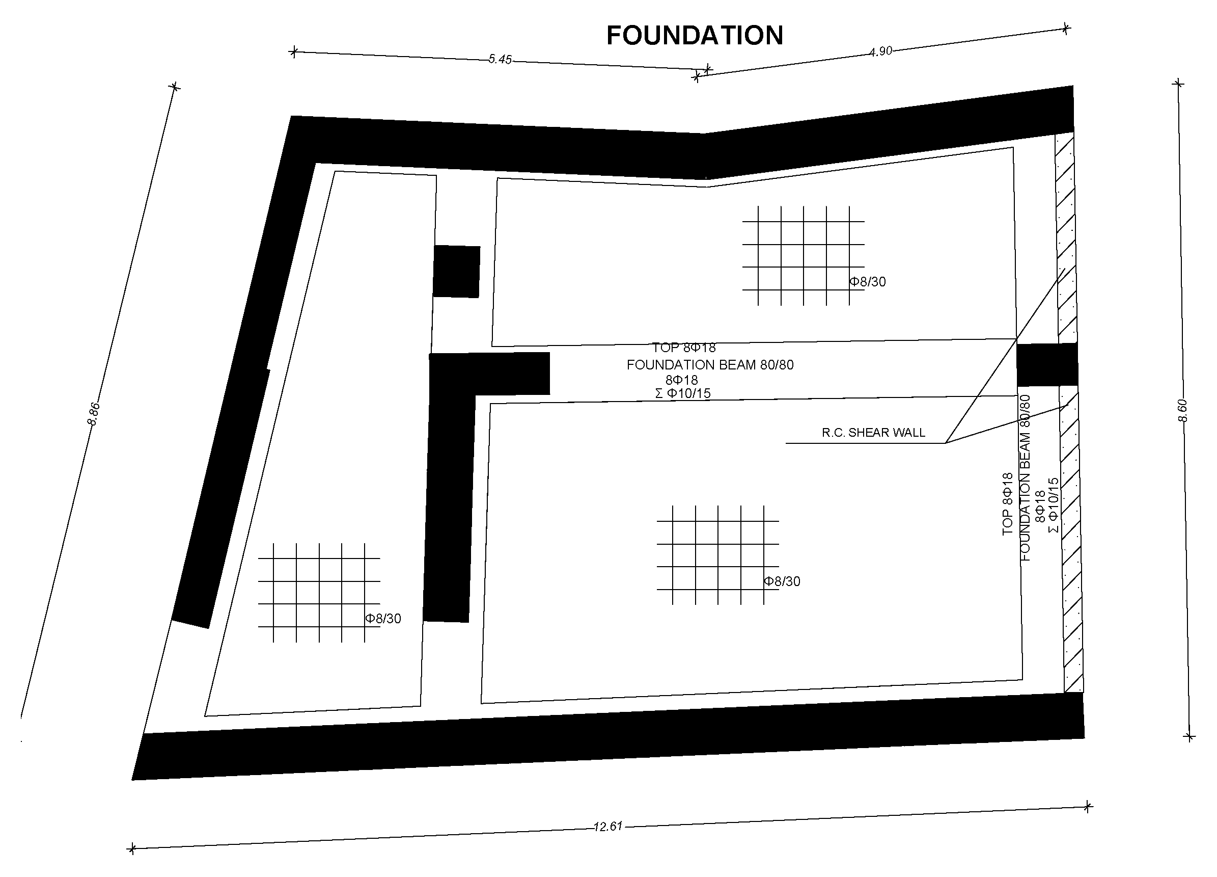
The structural strengthening of the foundation will be achieved with the use of a perimetric reinforced concrete raft foundation (Figure 18 and Figure 19).

5.4.3. Description of the Structural Model

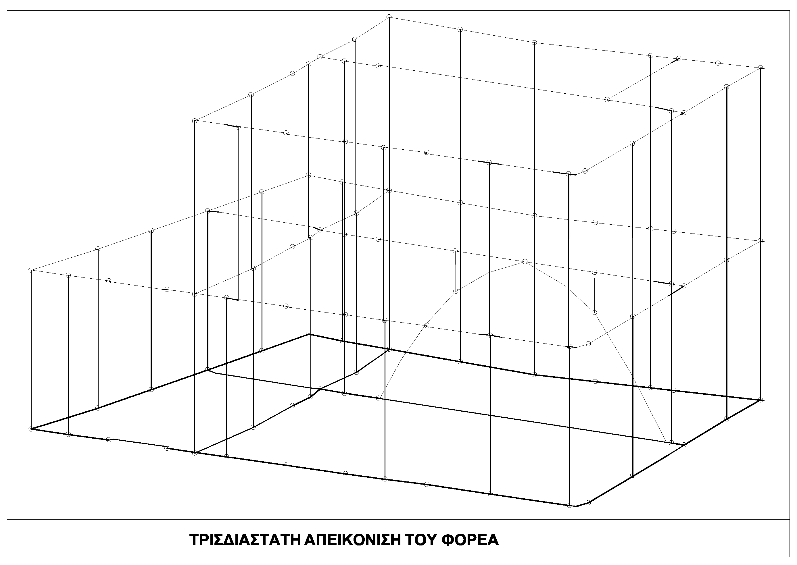
The structure was simulated with a 3D model comprised of linear elements (Figure 20) in the commercial structural analysis software FESPA, developed by the longest-running structural software firm in Greece, LH logismiki [31]. Eurocode 8 [28] and Eurocode 2 [32] were employed for the design. The authors are aware that more advanced models and analyses exist for masonry structures, such as equivalent frame modeling of masonry [33,34] or even discrete element analysis [35]; however, for a small-size urban house that also needs tie beams and other reinforced concrete elements, FESPA software was preferred, as it is time-saving, user-friendly and reliable.
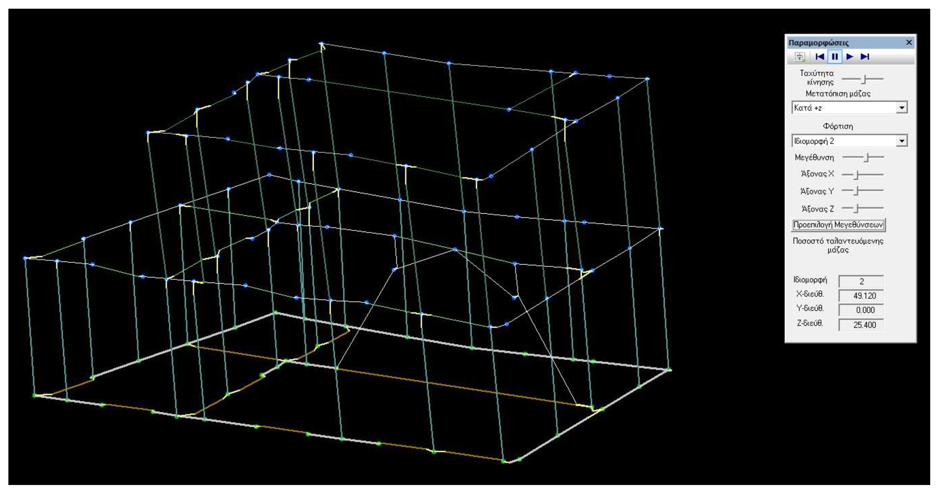
All material properties considered are given in Table 1. Dynamic response spectrum analysis with mass transfer was performed according to §4.3.3.3.1 of EC8. The center of mass of each floor was taken as displaced by the random eccentricity eai = 0.05 × Li, where Li is the dimension of the building perpendicular to the considered seismic direction. In this way, four independent models were available for analysis, in accordance with EC8-1 §4.3.2. The four models had mass eccentricity of +x, −x, +z and −z. Moreover, the seismic combination, as shown in Table 2, ran in the direction of 0° and 90°. Hence, a total of eight models were analyzed. Then, the calculation of the simultaneous values (with maximums) of the bending moments and shear and axial forces was undertaken with Gupta’s Absence [36], as described in EC8-1 §4.3.3.5.1(2)c.
The various live loads Q, QA, QB, QC, QD and QE are explained in EC2-1-1 §5.1.3(1)A(a) and shown in Figure 21.

5.4.4. Results of the Analysis

The eigenperiods shown in Table 3 were calculated for a mass transfer at +X.
Similar results were obtained for the other seven models with a mass eccentricity of −x, +z and −z at 0° and 90°. An example of the various eigenmodes is given in Figure 22.
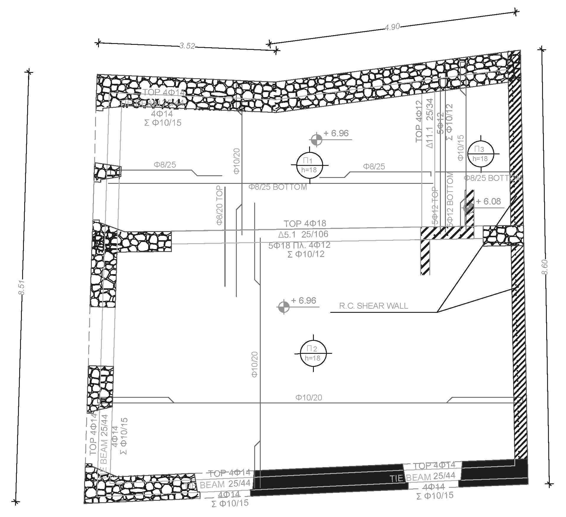
Finally, the software output the reinforcing details for all the reinforced concrete elements, as shown in Figure 23, Figure 24 and Figure 25.

5.5. Other Design Restrictions

The introduction of a contemporary heating, ventilation and air conditioning (HVAC) installation was deemed necessary. However, it was desired that the external units should not be visible and compromise the esthetics of the external shell of the structure. It was decided that the external units should be placed on the terrace, and the need to conceal any mechanical systems on the roof was satisfied by creating a split-level slab on the flat roof slab above the internal staircase. The area of the split-level slab was lowered by 0.88 m in order to encase it and render it invisible (Figure 26) from the street level. The drawings of the roof plan view indicate the exact position and show the lower part of the slab (Figure 27). The internal angle of the southwestern corner of the terrace was judged as optimal.

5.6. Budget Estimation

Table 4 provides a budget estimation for the restoration and reconstruction work. Although the last two years have witnessed significant fluctuations in the prices of construction materials, the authors still felt that it would be of some interest to present a revised budget based on the costs of work on such remote islands as a reference for other architectural conservationists.

5.7. Preparing for Future Climate Scenarios

The design solutions presented above also cater to future climate scenarios in the following senses:
  • Ingress of flood waters will be prevented by stabilizing the foundations with deep grouting and constructing an internal drainage system around the building to reduce ascending moisture;
  • The collection of rain water from all levels and its storage in the original cistern offer a sustainable water-supply system, and the water can then be used for non-drinking purposes (e.g., cleaning, flushing the toilets, etc.).
Moreover, reducing the carbon footprint of the building will be achieved by using both passive and active means:
  • By restoring the grouting and applying rendering to masonry, in combination with the large wall thickness, thermal insulation will be increased, thus reducing the total energy consumption for both heating in the winter and cooling in the summer;
  • By using efficient thermal insulation on the roof level, total energy consumption will be reduced;
  • By using double-glazed wooden doors/windows, the thermal insulation will also be increased and thermal infiltration reduced;
  • By using contemporary and energy-efficient HVAC systems, energy efficiency will be improved by means of level separation, as the house can be divided and used partially, thus reducing total energy consumption.

6. Conclusions

In the present paper, a rare case study of the conservation of an urban house constructed in 1850 in a current UNESCO protected area, the historic center (Chorá) of the island of Patmos, was discussed. To begin with, a brief analysis of the historical evolution of the boundaries of the Chorá settlement from AD 1132 until the 19th century was presented. Climatic deterioration factors applying to the area were listed, explaining the very poor maintenance condition of the structure. A debate on the reuse and “adaptive reuse” strategies for UNESCO protected monuments was employed as a medium leading to the design choice in this case study, that of reuse.
Following a discussion of the theoretical approaches, the next section was devoted to the description of the current condition of the urban house. The typology and morphology were analytically portrayed, the construction phases up to the period of the abandonment of the house were presented and a space-by-space analysis was provided, as the various spaces revealed by the excavation work was discussed. This particular diagnostic step was very significant as, in the restoration proposal, all established uses were maintained in the design process. Following that, the pathology of the structure was defined so that it could be reversed in the restoration proposal.
The merging of the architectural, structural and mechanical requirements was discussed through the lens of preparing for future climate scenarios. Following that, the restoration proposal was unfolded, including a design verification discussion, a full analysis of the conservation approach and a detailed description of the restoration work, which comprised:
  • The general layout of the living spaces;
  • Construction details for the floors and roof;
  • Details of the plastering and colorings;
  • Details of the doors and windows;
  • Details of the drainage system;
  • A complete analysis of the structural design considerations and restrictions;
  • Details of masonry walls and other elements;
  • Details of the reinforced concrete elements;
  • A description of the structural model;
  • A budget estimation;
  • A description of the key elements that will render the restored urban house ready for future climate scenarios.
The current paper offers solutions in cases in which a significant part of a structure has collapsed, but there exist proofs of how the original structure stood.
This paper constitutes an example of a real-life conservation project. The authors aimed to vividly demonstrate all the design aspects of such projects as the main contribution of the current paper, hoping that it can be used as a reference for other architectural conservationists around the world.

Author Contributions

Conceptualization and methodology, S.P.; historical data and pathology, S.P. and G.M.; surveying plots and architectural drawings, G.M. and G.S.; discussion of architectural proposal, G.M. and S.P.; structural analysis and discussion, S.P. and G.T.; writing—original draft preparation, S.P. and G.M.; writing—review and editing, S.P. and G.M. All authors have read and agreed to the published version of the manuscript.

Funding

This research received no external funding.

Data Availability Statement

Not applicable.

Acknowledgments

The authors wish to thank the journal Heritage for the invitation to contribute an article and for waiving the Article Processing Charge (APC).

Conflicts of Interest

The authors declare no conflict of interest.

References

  1. Rodwell, D. The Unesco World Heritage Convention, 1972–2012: Reflections and Directions. Hist. Environ. Policy Pract. 2012, 3, 64–85. [Google Scholar] [CrossRef]
  2. Papatzani, S.; Pnevmatikos, N.; Dimitroulias, K.; Michail, G.; Sapiridis, G.; Flentzouris, V. Mount Athos: Restoration of an almost Extinct Type of 18th–19th C. UNESCO Masonry OX Stable. Heritage 2021, 4, 1284–1303. [Google Scholar] [CrossRef]
  3. Iakovidis, C. Chora Patmou 1088–1912; Self-Published: Athens, Greece, 1978. (In Greek) [Google Scholar]
  4. Djebbour, I.; Biara, R.W. The challenge of adaptive reuse towards the sustainability of heritage buildings. Int. J. Conserv. Sci. 2020, 11, 519–530. [Google Scholar]
  5. Yung, E.H.K.; Chan, E.H.W. Implementation challenges to the adaptive reuse of heritage buildings: Towards the goals of sustainable, low carbon cities. Habitat Int. 2012, 36, 352–361. [Google Scholar] [CrossRef]
  6. Foster, G. Circular economy strategies for adaptive reuse of cultural heritage buildings to reduce environmental impacts. Resour. Conserv. Recycl. 2020, 152, 104507. [Google Scholar] [CrossRef]
  7. de la Calle-Vaquero, M.; García-Hernández, M.; de Miguel, S. Urban Planning Regulations for Tourism in the Context of Overtourism. Applications in Historic Centres. Sustainability 2021, 13, 70. [Google Scholar] [CrossRef]
  8. Uzqueda, A.; Garcia-Almirall, P.; Cornadó, C.; Vima-Grau, S. Critical Review of Public Policies for the Rehabilitation of Housing Stock: The Case of Barcelona. Buildings 2021, 11, 108. [Google Scholar] [CrossRef]
  9. Pedersen, A. Managing Tourism at World Heritage Sites: A Practical Manual for World Heritage Site Managers; UNESCO World Heritage Centre: Paris, France, 2002. [Google Scholar]
  10. Giannakopoulos, D.; Karekou, Z.; Menegaki, E.; Tsilimantou, E.; Ioannidis, C.; Maistrou, E.; Giannikouris, A.; Moropoulou, A. Reuse of Historic Buildings in the Medieval City of Rhodes to Comply with the Needs of Sustainable Urban Development. Land 2022, 11, 1214. [Google Scholar] [CrossRef]
  11. Douglas, J. Building Adaptation, 2nd ed.; Butterworth-Heinemann: Edinburgh, UK, 2006; ISBN 978-0750666671. [Google Scholar]
  12. Gravagnuolo, A.; De Angelis, R.; Iodice, S. Circular Economy Strategies in the Historic Built Environment: Cultural Heritage Adaptive Reuse. In Proceedings of the 18th Annual STS Conference Graz, Graz, Austria, 6–7 May 2019. Critical Issues in Science, Technology and Society Studies. [Google Scholar]
  13. International Council on Monuments and Sites (ICOMOS). International Charters for Conservation and Restoration; ICOMOS: Paris, France, 2001. [Google Scholar]
  14. Yazdani Mehr, S. Analysis of 19th and 20th Century Conservation Key Theories in Relation to Contemporary Adaptive Reuse of Heritage Buildings. Heritage 2019, 2, 920–937. [Google Scholar] [CrossRef] [Green Version]
  15. Tarrad, M.; Husban, S.M. The creation of guidelines for adaptive reuse of heritage buildings in Jordan-case study palace of the Ali Alkaid Basha (Jordan). Archit. Mod. Inf. Technol. 2021, 3, 64–78. [Google Scholar]
  16. Hein, M.F.; Houck, K.D. Construction Challenges of Adaptive Reuse of Historical Buildings in Europe. Int. J. Constr. Educ. Res. 2008, 4, 115–131. [Google Scholar] [CrossRef]
  17. Mısırlısoy, D.; Günçe, K. Adaptive reuse strategies for heritage buildings: A holistic approach. Sustain. Cities Soc. 2016, 26, 91–98. [Google Scholar] [CrossRef]
  18. Fernandes, A.; Figueira de Sousa, J.; Costa, J.P.; Neves, B. Mapping stakeholder perception on the challenges of brownfield sites’ redevelopment in waterfronts: The Tagus Estuary. Eur. Plan. Stud. 2020, 28, 2447–2464. [Google Scholar] [CrossRef]
  19. Yung, E.H.K.; Chan, E.H.W. Problem issues of public participation in built-heritage conservation: Two controversial cases in Hong Kong. Habitat Int. 2011, 35, 457–466. [Google Scholar] [CrossRef]
  20. Bourne, L.S. Reurbanization, Uneven Urban Development, and the Debate on New Urban Forms. Urban Geogr. 1996, 17, 690–713. [Google Scholar] [CrossRef]
  21. Remøy, H.; van der Voordt, T. Adaptive reuse of office buildings into housing: Opportunities and risks. Build. Res. Inf. 2014, 42, 381–390. [Google Scholar] [CrossRef]
  22. Dyson, K.; Matthews, J.; Love, P.E.D. Critical success factors of adapting heritage buildings: An exploratory study. Built Environ. Proj. Asset Manag. 2016, 6, 44–57. [Google Scholar] [CrossRef]
  23. Vrusho, B.; Pashako, F. Adaptive Reuse of Underused Industrial Sites, Case Study: The Superphosphate of Laç. In Proceedings of the INTBAU 2017: Putting Tradition into Practice: Heritage, Place and Design; Amoruso, G., Ed.; Springer International Publishing: Cham, Switzerland, 2018; pp. 1097–1112. [Google Scholar]
  24. International Council on Monuments and Sites (ICOMOS). International Charter for the Conservation and Restoration of Monuments and Sites: The Venice Charter; ICOMOS: Paris, France, 1964. [Google Scholar]
  25. Sassu, M.; Zarins, J.; Giresini, L.; Newton, L. The ‘Triple R’ Approach on the Restoration of Archaeological Dry Stone City Walls: Procedures and Application to a UNESCO World Heritage Site in Oman. Conserv. Manag. Archaeol. Sites 2017, 19, 106–125. [Google Scholar] [CrossRef]
  26. Khalaf, R.W. The Implementation of the UNESCO World Heritage Convention: Continuity and Compatibility as Qualifying Conditions of Integrity. Heritage 2020, 3, 384–401. [Google Scholar] [CrossRef]
  27. Khalaf, R.W. Authenticity or Continuity in the Implementation of the UNESCO World Heritage Convention? Scrutinizing Statements of Outstanding Universal Value, 1978–2019. Heritage 2020, 3, 243–274. [Google Scholar] [CrossRef] [Green Version]
  28. ENV 1998-1-4:1996; Eurocode 8: Design Provisions for Earthquake Resistance of Structures. British Standards Institution: London, UK, 1996.
  29. BS EN 1996-1-1:2005; Eurocode 6. Design of Masonry Structures. General Rules for Reinforced and Unreinforced Masonry Structures. CEN: Brussels, Belgium, 2005; p. 128.
  30. Spyrakos, C. Κατασκευές από Τοιχοποιία. Aποτίμηση και επεμβάσεις για σεισμικά φορτία (In Greek: Masonry Structures. Verification and Interventions for Seismic Loads); Εργoνόμος ΙΚΕ (in Greek Ergonomos IKE): Athens, Greece, 2019; ISBN 9786180012569. [Google Scholar]
  31. LH Logismiki Fespa Structural Analysis Software, LH Logismiki: Athens, Greece.
  32. EN 1992-1-1:2004; Eurocode 2: Design of Concrete Structures. Part 1-1: General Rules and Rules of Building. BSI: London, UK, 2004.
  33. Formisano, A.; Florio, G.; Landolfo, R.; Mazzolani, F.M. Numerical calibration of an easy method for seismic behaviour assessment on large scale of masonry building aggregates. Adv. Eng. Softw. 2015, 80, 116–138. [Google Scholar] [CrossRef] [Green Version]
  34. Lagomarsino, S.; Penna, A.; Galasco, A.; Cattari, S. TREMURI program: An equivalent frame model for the nonlinear seismic analysis of masonry buildings. Eng. Struct. 2013, 56, 1787–1799. [Google Scholar] [CrossRef]
  35. Pantò, B.; Cannizzaro, F.; Caddemi, S.; Caliò, I. 3D macro-element modelling approach for seismic assessment of historical masonry churches. Adv. Eng. Softw. 2016, 97, 40–59. [Google Scholar] [CrossRef]
  36. Gupta, A.K. Response Spectrum Method in Seismic Analysis and Design of Structures (New Directions in Civil Engineering), 1st ed.; Routledge: London, UK; CRC Press: Boca Raton, FL, USA, 2017; ISBN 978-0849386282. [Google Scholar]
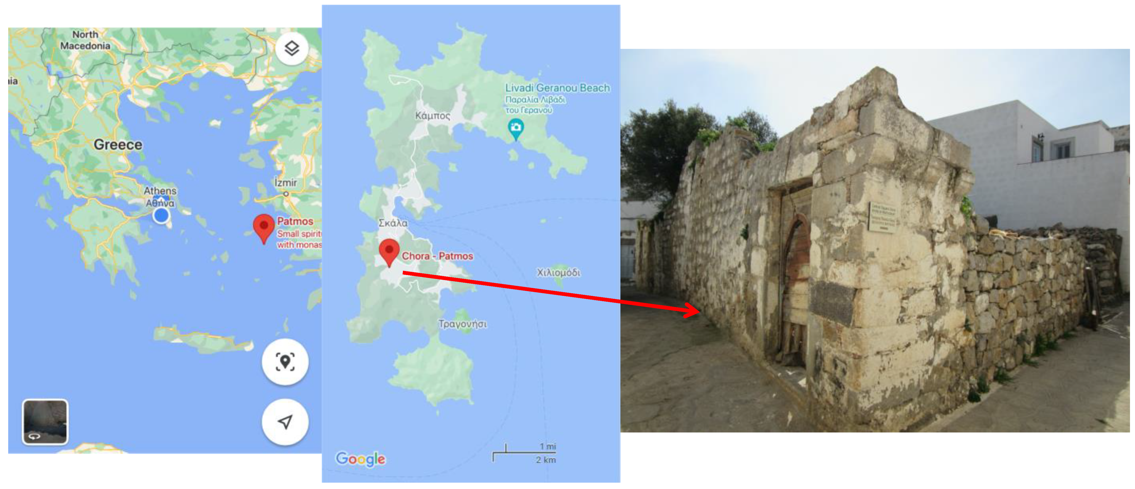
Figure 1. Patmos on the map, Chorá’s boundaries and the location of the urban house (Google maps).
Heritage 05 00161 g001
Figure 2. The monastery of Saint John the Theologian and Santa Lesbia Square (Google Earth).
Heritage 05 00161 g002
Figure 3. The evolution of Chorá since AD 1132 [3].
Heritage 05 00161 g003
Figure 4. Engraving of the construction date (1850) of the building.
Heritage 05 00161 g004
Figure 5. Construction phases of the building.
Heritage 05 00161 g005
Figure 6. Ground floor plan of the building.
Heritage 05 00161 g006
Figure 7. Northern view of the building.
Heritage 05 00161 g007
Figure 8. Eastern view of the building.
Heritage 05 00161 g008
Figure 9. Characteristic pathology of the building: (a,c) internal walls, (b) northern external wall, and (d) arch.
Heritage 05 00161 g009
Figure 10. Characteristic pathology of the building in space X01, (a) staircase leading to first floor, (b) the cistern and (c) the cook stove.
Heritage 05 00161 g010
Figure 11. Characteristic pathology of the building: (a) northeastern corner of the property and (b) stone elements revealed in excavations.
Heritage 05 00161 g011
Figure 12. Section A-A—characteristic pathology of the building.
Heritage 05 00161 g012
Figure 13. Section Γ-Γ—characteristic pathology of the building.
Heritage 05 00161 g013
Figure 14. Three-dimensional (3D) representation of the proposal for the restoration of the building.
Heritage 05 00161 g014
Figure 15. Salvaged stones and monolithic stone lintels of the building to be reused.
Heritage 05 00161 g015
Figure 16. Ground floor plan of the proposal for the restoration of the building.
Heritage 05 00161 g016
Figure 17. First floor plan in the proposal for the restoration of the building.
Heritage 05 00161 g017
Figure 18. Section BB of the proposal for the restoration of the building.
Heritage 05 00161 g018
Figure 19. Eastern elevation in the proposal for the restoration of the building.
Heritage 05 00161 g019
Figure 20. Three-dimensional (3D) representation of the structural model.
Heritage 05 00161 g020
Figure 21. Loads Q, QA, QB, QC, QD and QE.
Heritage 05 00161 g021
Figure 22. Mass eccentricity +Z at 0°, exciting 49.12% of the total mass in the x-direction and 25.4% of the total mass in the z-direction.
Heritage 05 00161 g022
Figure 23. Steel reinforcement of members at the foundation level.
Heritage 05 00161 g023
Figure 24. Steel reinforcement of members at the ground floor (reflected ceiling) level.
Heritage 05 00161 g024
Figure 25. Steel reinforcement of members at the first floor (reflected ceiling) level.
Heritage 05 00161 g025
Figure 26. Section AA of the proposal for the restoration of the building.
Heritage 05 00161 g026
Figure 27. Roof plan in the proposal for the restoration of the building.
Heritage 05 00161 g027
Table 1. Material properties.
MaterialClass
ConcreteC25/30
Reinforcing steelB500C
TimberC24
Table 2. Loading combinations for the response spectrum analysis.
Load Combinations
G + 1.05Q
1.35G + 1.05QA
1.35G + 1.05QB
1.35G + 1.05QC
1.35G + 1.05QD
1.35G + 1.05QE
1.15G + 1.50Q
1.15G + 1.50QA
1.15G + 1.50QB
1.15G + 1.50QC
1.15G + 1.50QD
1.15G + 1.50QE
1.00G + 1.00Q
1.00 [G + ψ2xQ]
1.00 × G + ψ2 × Q ± 1.00{E[x] + E[z]}
Table 3. Loading combinations for the response spectrum analysis.
Eigenmode (#)Eigenperiod (sec)X-Direction (%)Z-Direction (%)
10.105621.15528.414
20.074349.39426.527
30.050111.35431.194
40.04420.0808.942
50.036213.2831.750
60.02653.2470.335
70.02420.7920.124
80.02200.0000.236
90.01870.3990.000
Table 4. Budget for work.
WorkCost (EUR)
Excavations4000.00
Backfilling2000.00
Demolitions3000.00
Reinforced concrete15,000.00
Masonry walls30,000.00
Masonry restoration/injections and grouting20,000.00
Roof/floor construction15,000.00
Dry walls10,000.00
Rendering4000.00
Doors/windows8000.00
Wood work2500.00
Insulation2000.00
Stairs4000.00
Paint3000.00
MEP and HVAC10,000.00
Total132,500.00
Publisher’s Note: MDPI stays neutral with regard to jurisdictional claims in published maps and institutional affiliations.