Abstract
For preservation efforts and stability assessment of historic structures it is imperative to understand the extent of existing damages and possible modes for how they could have occurred. The aim of this work is to illustrate the importance of integrating documentation, non-destructive testing, and numerical modeling for damage assessment of heritage structures. In particular, this work explores the synthesis of these techniques on a plastered masonry wall in Palazzo Vecchio. Laser scanning was used to capture the geometry of the wall while terrestrial photogrammetry and high-resolution images were used to document the magnitude of cracking in the plaster layer. High resolution thermal images were used to document the distribution of stones and additional cracks not visible through the plaster layer. The results of documentation and non-destructive testing were used to generate an as-built model for structural analysis. Finite distinct element modeling was used to simulate the response of the wall to a series of loading conditions. By comparing the results of simulation to existing crack patterns, theories for how the damage occurred were generated.
1. Introduction
Adaptive reuse, rehabilitation, and renovation of existing buildings have recently had a resurgence of interest due to changing economic conditions, concern for historic preservation, space shortages, emphasis on low-carbon impact projects, etc. [1,2,3,4]. However, accurate damage assessment of existing buildings is required before any improvements can be carried out. Damage assessment is a process aimed at providing accurate information about structural condition and is generally used to plan maintenance and structural updating activities as well as monitor safety [5]. Damage assessment combines characterization of damages on an existing structure and comprehending how damages originated; this can later be used in structural health assessment to understand how damages could evolve and affect the stability of a structure.
Previous works have carried out preliminary damage assessment of structures using solely surface documentation techniques [6,7,8]. A preliminary assessment, as defined by ISO 13822, encompasses studying existing documents about a site, preliminary inspection, preliminary check, and recommendations for a detailed assessment. Preliminary documentation techniques, such as photogrammetry and laser scanning, can provide accuracy 3D geometry with millimeter accuracy [9,10,11]. However, both of these techniques are line-of-sight techniques; this means that the device only records measurements from the first surface it sees and nothing beyond that.
Methodologies for using these surface level techniques for preliminary assessment have been outlined by Olsen et al. (2003), Pesci et al. (2011), and Pesci et al. (2012). Olsen et al. (2003) discussed a method for in situ change analysis and monitoring of public infrastructure using terrestrial laser scanning while Pesci et al. (2011) and Pesci et al. (2012) specifically focused on applications of laser scanning to historic structures [6,7,8]. In those works, the laser scan data was compared to reference fit planes to establish preliminary hypotheses about how the structures had changed over time. Similarly, Bonali et al. (2014) used terrestrial laser scanning to understand damages on a historic structure after an earthquake [12]. In that work, the deformation of the structure was inferred from the terrestrial laser scans that had been made before and after the earthquake. Napolitano et al. (2019) combined photogrammetry, laser scanning, and distinct element modeling to elucidate the causes of damage on a masonry foundation wall [13]. That work illustrated, on both experimental and case study masonry walls, that this combination of line-of-sight documentation with numerical methods could differentiate crack patterns induced by different settlement conditions.
Using these methods, documentation of damage is limited to changes in visible material or geometric properties of a structural system such as boundary conditions, connections, and missing elements. However not all damages on a building are apparent with the naked eye. For this reason, it is critical to integrate additional methods of sub-surface investigation, such as thermal imaging with documentation methods, such as photogrammetry and laser scanning, for a more detailed assessment. Additionally, while an understanding of how damages can affect a building can be qualitatively predicted, to ensure the safety and serviceability of a structure, numerical modeling is also needed.
As defined by ISO 13822, detailed assessment involves a detailed inspection, material testing, and structural analysis [14]. For an example of a detailed assessment, Carpinteri et al. (2005) combined nondestructive evaluation with non-linear numerical modeling to assess damages on a historical masonry tower in Alba, Italy [15]. That work found that by combining geometrical surveys, flat-jack tests, and thermography with non-linear finite element modeling, they were able to provide a more comprehensive and detailed stability assessment. Additionally, Meola et al. (2005) and Kilic (2015) both outlined how to combine infrared thermography and geophysical methods for defect detection and health assessment of historic structures [16,17]. Examples of in situ buildings were included to illustrate the applicability of the method. Lastly, Costanzo et al. (2014) illustrated the benefits of combining terrestrial laser scanning and infrared thermography [18]. In this work, the combined method was outlined and applied to a monumental compound in Italy to illustrate the benefits of applying it to historic structures. This approach can be found quite frequently in the literature [19,20,21,22,23].
While these works illustrated the capabilities of an assessment which utilized multiple levels of documentation and analysis, the benefits of multi-level integration are explicitly discussed in Laefer et al. (2010) [24]. In this work, the reliability of crack detection methods for baseline condition assessments was tested on various levels of documentation. It was found that in comparison to LiDAR, inspection of images is faster and detects more cracks; however, more information about the geometry of the structure can be gleaned from the LiDAR data. Therefore, both types of documentation should be integrated together for defect detection. Similarly, Binda et al. (2011) and Shrestha et al. (2017) illustrated the benefits of multi-level and interdisciplinary documentation for diagnosing damages. Binda et al. (2011) combined structural surveying with sonic pulse velocity, radar, thermogrpahic, single and double flat jack, and dynamic investigation tests to document a historic fort damaged in an earthquake [25]; Shrestha et al. (2017) combined photogrammetry, laser scanning, and ground penetrating radar to document a historic temple damaged in an earthquake [26]. Both studies stated that in future workflows for preventative conservation, numerical simulations should be integrated.
While previous works have shown the success of combining documentation, non-destructive evaluation, and numerical modeling for a myriad of structural purposes, in all cases the most probable cause of the damage was known. The aim of the present work is to provide further insights into the importance of integrating non-destructive testing, laser scanning, and numerical modeling for damage assessment to elucidate unknown origins of damage. This is presented through a case study of a wall in the Room of the Elements in Palazzo Vecchio in Florence, Italy. A qualitative crack map of the existing damages was made using a combination of documentation methods. Subsequently, a three-dimensional model was generated for numerical simulation. Additionally, whereas Carpinteri et al. (2005) uses a single, known input load [15], this work, given the existing crack pattern, evaluates several load combinations and yields the most probable loading scenario which caused the existing damage. Using finite-distinct element modeling, the wall was simulated under a variety of loading conditions including dead load and settlement. The results of the simulations were directly compared to the existing crack patterns to understand how they could have originated. By understanding the extent and origins of the damage, a more comprehensive assessment of a structure’s health can be made. Additionally, a second study was carried out examining the impacts of different materials used as infill. This investigation into how different initial assumptions can alter the results of damage assessment is used as evidence for the need of integrated documentation using not only laser scanning and thermal imaging, but also ground penetrating radar (GPR).
2. Case Study
Palazzo Vecchio (Figure 1), the center of Florentine power since the 14th century, still serves as the city hall in Florence [27]. The front façade of Palazzo Vecchio, constructed in 1298, is predated by the surrounding medieval buildings which have been joined over time to create the Southeast corner of the Palazzo. One room in particular, Sala degli Elementi (or Room of the Elements), has been studied to diagnose the potential causes of observed cracking. The formation of Palazzo Vecchio over many years consisted of the “assemblage” of existing structures into one larger building, which resulted in their extremely complicated structural interactions.
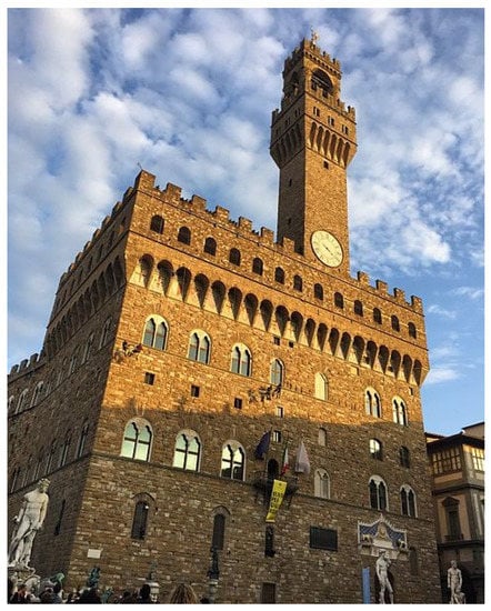
Figure 1.
Palazzo Vecchio’s western façade
As a result of this combination process, there were many connection points, materials (with different properties), and different types of workmanship utilized; therefore, comprehensive archival research was required. This was carried out specifically for the Room of the Elements, which is located on the top floor of Palazzo Vecchio in the Southeast corner of the building in accordance with the “knowledge process” outlined in “Valutazione e riduzione del rischio sismico del patrimonio culturale con riferimento alle Norme techniche per le construzioni di cui al D.M.” [28]. Observed damages have been a cause of concern for some time, beginning as early as 1558, and are still being studied today [29]. The Room of the Elements exemplifies one of the largest difficulties when attempting to remedy damages in historical constructions: the structure and the art are interwoven; all four walls of the room are decorated in frescoes. These artworks are bonded to the structure and any interventions should be as minimally intrusive as possible; therefore, non-destructive techniques were crucial to the success of this work. Previously, LiDAR scans were carried out for the Room of the Elements [30]. Crack mapping of this wall was based on not only information gathered in on-site inspection, but also on this previous work. Following the guidelines for the knowledge process outlined in “Valutazione e riduzione del rischio sismico del patrimonio culturale con riferimento alle Norme techniche per le construzioni di cui al D.M.”, a comprehensive documentation process including archival research, geometrical surveys, non-destructive testing, was completed prior to structural analysis.
3. Line-Of-Sight Methods for Documentation
Terrestrial laser scanning (TLS) best practice [31] was used to form a comprehensive geometric record of the Room of the Elements using a Faro Focus 3D x130 laser scanner with 1–2 mm resolution; six scans were used to document the rectangular room. the scans were aligned using FARO Scene with cloud-to-cloud alignment; the mean error was 1–2 mm. In addition to documenting this room, the surrounding rooms, staircase, balcony, and exterior walls were also documented using laser scanning at a coarser resolution of 5–7 mm.
Terrestrial photogrammetry was used to augment the laser scan point cloud data. Using a Canon 5D DSLR camera, 200 images were taken in the Room of the Elements; best practices were utilized [32,33,34,35,36]. A 3D model was generated from the photogrammetry data and aligned to the TLS data; the raw images from photogrammmetry were used to texture the TLS model [37]. High-resolution photographs were acquired using two Panasonic LUMIX GF-1 cameras in stereo to document the network of cracks apparent through the frescoes (Figure 2).
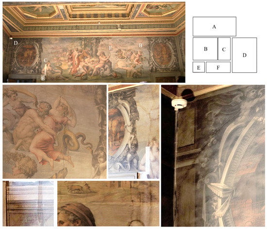
Figure 2.
High resolution images of cracks in the Room of the Elements: (A) full illustration of western wall, (B–F) images of specific cracks on the western wall.
This imaging augments the data from TLS which was not always able to capture the locations of these fine cracks. Figure 2A depicts the entirety of the western wall with specific cracks (Figure 2B–F) labeled on it. Figure 2B shows cracking which goes through the woman’s arm, face, and right leg as well as through the serpent. Figure 2C illustrates cracking where sections have been recently intervened on (white rectangle); this crack starts in two parts on the ceiling, joins above the woman’s head, continues through her right shoulder and then splits in two cracks near the door which can be seen in Figure 2E. Figure 2D shows a diagonal crack on the top left corner of the west wall. Figure 2F shows cracking in the middle of the western wall. As stated above however, these methods only provide information about the surface of the fresco.
4. Non-Destructive Evaluation
Thermography is a well-established method for non-destructive evaluation of frescoes [38,39,40]. Additionally, while thermography has been used to find cracks in masonry walls [16], it has also been particularly successful in identifying the locations of cracks in masonry walls covered in plaster [41]. For this reason, high-resolution thermal images were captured (Figure 3). 72 images were captured using a FLIR A615 camera; best practices for setup and acquisition were carried out according to the ASTM C1153-10 standard [42]. While some cracks were more obvious in the thermal image, others were apparent using both methods. The cracks in regions G and H of the thermal image were visible prior to thermal imaging and can be seen in Figure 2D,C respectively. While the upper sections of region J were apparent using visible methods, lower sections of the crack were exposed using thermal imaging. Additionally, many of the cracks in region I were not visible except the one depicted in Figure 2F. Lastly, the crack in region K was not visible at all until thermal imaging was used.
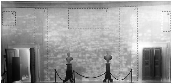
Figure 3.
Thermal image with outlines in highlighting cracks in regions of interest.
Since the emissivity (e) varies between limestone (e = 0.96 [43]) and mortar/concrete infill (e = 0.87–0.94 and e = 0.92 respectively [43]), the thermal images could be used to understand the basics of the structure’s geometry under the fresco layer without damaging the art. However, since the emissivity ranges of brick (e = 0.81–0.94 [43]) and mortar / concrete infill overlap, specific identification of these materials was not possible using the techniques available. This limitation is addressed in subsequent sections.
The thermal images were registered to laser scan data (Figure 4) to enable inspection of details in both the visible and infrared range while maintaining an understanding of the structure as a whole. The method outlined in Hess et al. (2015) was utilized for this registration [29]. Using this method, it was evident that cracks which permeated the plaster layer extended into the stone wall. Additionally, it depicted several cracks that had not yet propagated through the fresco.
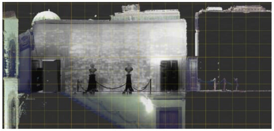
Figure 4.
Image showing the laser scan model with the thermal image mosaic draped over it.
5. Mapping Existing Crack Patterns
Using a combination of information from laser scanning, photogrammetry, thermography, as well as previous crack maps, a new map of the existing cracks and their relative sizes can be found in Figure 5. Since the cracks are not all visible with line-of-sight methods, the magnitudes of the cracks are approximate. In this plot, red lines denote cracks with the width on the order of 1 cm or larger, yellow denotes those on the scale of 1 mm, and orange denotes those between these limits. As can be seen in Figure 5, the widest cracks on the wall occur in the vicinity of the door jams. The widest cracks originate there and then reduce in magnitude as they continue to propagate through the wall’s height. Smaller cracks can be seen at the corners of the room as well as some in the top-middle section of the wall.
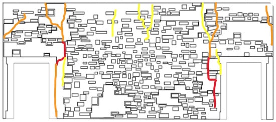
Figure 5.
Map of existing cracks on the foundation wall. Red indicates cracking over 1 cm; yellow indicates cracking on the order of 1 mm; orange indicates cracking in between these two limits.
6. Numerical Modeling
6.1. Levels of Modeling and Analysis
Often masonry projects utilize simplified micro-models for structural analysis [44,45,46]). In a simplified micro-model of a masonry wall, the mortar joints are not explicitly modeled and bricks are fictitiously expanded to compensate for the missing geometry. In this case, the bricks are the individual elements and a fictitious interfacial element located inside the mortar is used as the contact point of two blocks to govern their relative motion. Another approach that has been used is detailed micro-modeling where the geometry of the joints is explicitly modeled [13]. Here, the bricks are represented as individual elements, the mortar is represented as a continuous, single element and the interface is defined between the brick and mortar. Based on existing conditions, detailed micro-modeling was used to capture damages occurring not only at the interfaces of blocks, but also within bricks, stones, mortar, and infill.
“Valutazione e riduzione del rischio sismico del patrimonio culturale con riferimento alle Norme techniche per le construzioni di cui al D.M.” outlines levels for analyzing structural behavior of masonry construction [28]. While this document addresses seismic analysis, an analogy can be made between the levels outlined in that document and the loading mechanisms addressed here. LV1 (level 1) includes only preliminary evaluation and analysis, LV2 includes analysis in conjunction with local interventions, and LV3 includes evaluations in conjunction with widespread interventions [28]. Using these definitions, the present work falls within the category of LV1 where preliminary analysis has been made to understand the structural system, but is not in conjunction with any specific preservation or intervention plans. A complete geometric survey of the damaged area including a map of the existing cracks has been included.
6.2. Theory and Background for Numerical Modeling
Distinct element modeling (DEM) is a method of discontinuous structural analysis which enables large displacements and rotations between discrete bodies in a system. The governing equation for displacement and rotation of individual blocks can be expressed as Equations (1) and (2) respectively [47]. For more on theory behind the numerical modeling, refer to [47].
where
- i = block number
- = acceleration of the block centroid
- = velocity of the block centroid
- = the viscous (mass-proportional) damping constant
- = sum of forces acting on the block
- m = block mass
- gravitational acceleration vector, and
- = angular acceleration about the principal axis
- = angular velocity about the principal axis
- = principal moment of inertia
- I = total torque
Previously, this method has been applied successfully to model the behavior of historic masonry structures [44,48]. In these works, a simplified micro-modeling approach was used where only masonry units (bricks, stones) were explicitly modeled (not mortar) to visualize displacements of individual stones/bricks under specific loading conditions. The combination of DEM and simplified micro-modeling was acceptable for these studies since any cracks or movement was expected/reported to be at the interface of masonry units; therefore movement and stresses within the mortar were not required. However for the present study, cracks have been found to occur in regions of infill and mortar joints. To capture failure within these regions (not limited to interfaces of stones) detailed micro-modeling was used. Additionally since cracks were seen to form in infill and mortar, a numerical method which could capture stresses developing in these deformable materials was desirable. For this reason, finite-distinct element modeling (FDEM) of a detailed micro-model was selected as the appropriate approach. The main difference between DEM and FDEM is the deformability of the blocks. While in DEM, the geometry of individual blocks is rigid, in FDEM, the blocks themselves can deform under loading and stresses are allowed to develop. In FDEM, individual blocks are discretized into finite-difference tetrahedral elements and the equation of motion for each grid point (i, j) in the tetrahedral can be defined as Equation (3) [47].
where
- s = surface enclosing the mass, m, which is concentrated at the grid point
- = zone stress tensor
- = unit outward normal from the surface
FDEM has been successfully applied to historic structures previously. Pulatsu et al. (2018) highlighted the use of FDEM for analyzing masonry-soil interactions for bridges [49] and Napolitano et al. (2019) preliminarily outlined the use of FDEM to model mortar-stone interaction [13]. Additionally, the approach of comparing crack patterns in FDEM/DEM simulations and existing cracks in masonry walls to ascertain unknown damage conditions has been used in Napolitano et al. (2019) [13] as well as proven against experimental testing of masonry walls in Napolitano et al. (2018) [50]. In the present work, FDEM will be applied to detailed micro-models of the masonry wall in the Room of the Elements to understand what could have caused the present damage.
6.3. Model Parameters
Using FDEM, the computations required are too heavy to run the analysis for the entirety of the structure. It is accepted in the literature to make simplifications to the structure or only examine a select part due to computational limitations [46,51,52,53]. However, to analyze a single wall of a complex building, proper inspection and proper assumptions about the boundary conditions should be established. Therefore, linear FEM of the whole structure was used to establish boundary conditions specific to this wall section [54]. The loads from the parts of upper parts of the structure and the roof incident upon the selected wall section were calculated as a distributed load. The distributed load was then applied to the FDEM model as a boundary condition. By taking into account the loads of the larger, more complex structure, a more rigorous analysis of this wall section is possible.
In addition to calculating the boundary conditions at the top of the wall, the boundary conditions along the sides of the wall were also calculated. The volume of the masonry walls in the adjacent rooms was calculated based on the results of TLS. In lieu of modeling both adjacent wall sections, a slender block the height of the wall was placed on either side of the wall section. The density of these simulated slender blocks was directly related to the density and volume of the adjacent wall sections and inversely related to its own volume as Equation (4) gives.
where
- = density of the simulated slender block
- = volume of the simulated slender block
- = density of the true, adjacent masonry wall
- = volume of the true, adjacent masonry wall
Using the boundary conditions from linear FEM of the larger, more complex structure, FDEM models of the wall were created. This approach enables accurate assumptions about the boundary conditions of this wall while still enabling more detailed computational analysis.
To ensure the accuracy of the numerical model’s geometry, the locations and sizes of the stones, mortar, and infill are directly derived from a combination of the laser scan, photogrammetry, and thermal imaging data (Figure 3B). This case study is a prime example of the importance of combing different types of data to understand the health of a building since the geometry of the stones cannot be seen through the frescoes. Additionally, there are no historical records which indicate the construction patterns. Therefore, the locations of the stones were only evident when a thermal camera was used.
Even with the use of both TLS and thermal imaging, unknowns about the configuration of the masonry were still present. As discussed above, in the thermal images it was not clear whether some sections of the wall were composed of brick or concrete infill. If GPR was performed on the walls, it would also have augmented this process; however, GPR data was not available. ISO 13822 indicates that uncertainties should be accounted for during assessment [14]. Therefore, two different numerical models were considered when trying to understand the evolution of the current crack pattern: (1) one with brick infill (Figure 6A) and (2) one with concrete infill (Figure 6B). In Figure 6, the blue sections are brick, the green sections are stones, the pink sections are concrete infill, and the white sections in the wall are mortar. These two materials were used due to archival research about construction materials in other parts of the building. When generating the geometry, the stones, bricks, and concrete are modeled as individual ‘blocks’ the thickness of the wall (0.64 m). As the wall is above-ground, the thickness can be garnered from the laser scan data of the entire complex. ‘Blocks’ will be used when referring to an element in the simulation which can move independently of other sections. The mortar was generated as the difference of the stones, infill (concrete and brick), and the total wall geometry; therefore it is all connected. Thus, the mortar is also modeled as an individual concave block. The discrete blocks of the model were then converted into a triangular meshes with edge lengths between 0.3m and 0.5m; these lengths were sufficient for a balance of accuracy and computational efficiency. Thus, the stones and bricks were modeled as individual deformable meshes while the sections of infill and the mortar were modeled as continuous deformable material.
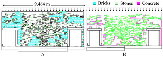
Figure 6.
Input geometry for numerical modeling. (A) wall with brick infill and middle settlement configuration (B) wall with concrete infill and left side settlement configuration.
The structural response of the resulting 3D geometry was simulated using 3DEC, a finite-distinct element modeling (FDEM) software. The constitutive model used was a Mohr-Coulomb model as this showed good performance in previous works [44]. As material testing was not possible for the present scenario, the values were derived from the literature and can be found in Table 1 and Table 2. Previous studies have used values from the literature when experimental testing is not possible and have had success with this method [55]. Additionally, without destructive testing an approximation was made where the joint materials have been assumed to be the same for the different interactions.

Table 1.
Material properties of blocks in the masonry wall.

Table 2.
Material properties of joints in the masonry wall.
6.4. Loading Conditions for the Numerical Model
The wall of the Room of the Elements was simulated under several loading combinations, the first of which was the dead load (self-weight) of the superstructure. Additionally, settlement loading was considered due to apparent floor deformations. Figure 7 was generated by comparing the laser scan data with a flat reference plane and illustrates these deformations. The wall with a high degree of cracking being considered in the present study is the west wall.
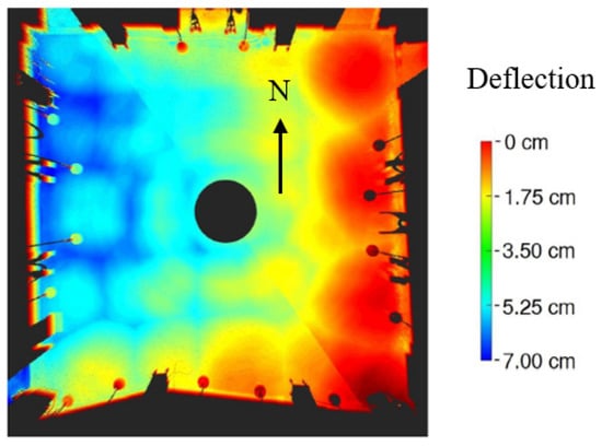
Figure 7.
Settlement of the floor in the Room of the Elements; the west wall was analyzed in this work due to cracking.
Three different settlement types with different magnitudes were considered. They are called “L”, “R” and “M” standing for settlement of the left side of the wall as described by the base in Figure 6B, right side as described by the inverse of the base in Figure 6B, and middle as described by the base in Figure 6A respectively. These three were chosen as they represent comprehensively the span of the possible settlement space in a computationally efficient way (i.e., there are infinite combinations of settlement). L and R represent possible types of settlement on each side of the room, whereas M represents possible settlements between those extremes. 0.05 m was selected for the settlement depth as it was within the middle range of values found in Figure 7. During analysis stages, it became apparent that middle settlement was the most probable cause of existing damage. Thus, 0.1 m settlement was also included to understand how variations in the magnitude of settlement depth could alter the magnitudes and locations of resulting cracks.
7. Diagnosing Crack Patterns
Figure 8 is a plot of the displacement magnitudes for each block under the different loading situations. The magnitude of displacement was dominated by the vertical displacement term (in the plane of gravity) as there was limited out-of-plane or horizontal movement; this agrees with what was expected from the selected loading conditions. The text to the left of the figures indicates the loading condition imposed to generate the results. In the case of settlement, the number indicates the depth of settlement while the letter refers to the section which is settled as described above. The results of simulation for both the brick and the concrete infill for each loading condition are displayed. The blocks colored in red indicate a large degree of displacement while the blue indicates little to no movement occurring. The scale for the visualization was set the same across all simulations to enable comparison. This scale was chosen to maximize what could be viewed in the cases with the least displacement (dead load) as well as the cases with the most displacement (0.1 m M); however this does make it harder to see larger movements which occur for the 0.1 m M case.
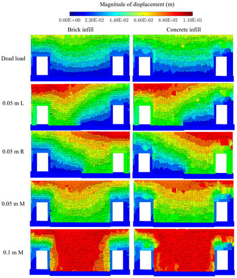
Figure 8.
Displacement magnitudes of the existing geometry under combinations of dead load and settlement for brick infill and concrete infill; text value (m) indicates magnitude of settlement, while L, R, and M indicate settlement of left, right, and middle part of the wall, respectively.
As can be seen in Figure 8 the displacement of the blocks followed expected patterns of movement for each loading scenario. In the case where there was only dead load of the superstructure and the wall itself applied, there are relatively small displacements which terminate over the doors and gradually decrease over the height of the wall. This same displacement pattern can be seen for both types of infill with variations just based on geometry. Comparing the displacement magnitudes across dead load, 0.05 m M, and 0.1 m M the displacement magnitudes increase as expected with the increase in settlement depth. The middle section of the wall which experiences the settlement moves, while the sections directly above the door frames move less. Lastly, in the case where the left and right sides are settled, the expected movement on the left and right side respectively occurs.
Additionally it should be noted that the patterns of displacement for the settlement load cases closely align with each other and, on this scale, appear independent of infill material. While the plots of displacement can be utilized to evaluate if the results of simulation match with expectation, they are not easy to compare with the existing conditions of the wall. On the wall, the cracks are the most explicit form of damage which are correlated with both the mechanism caused them as well as the severity of that mechanism was. For this reason, it is helpful to plot separations between the blocks, or crack widths, rather than the displacements.
Figure 9 is a plot of the crack widths incurred in the different loading simulations for both the wall with brick infill and the wall with concrete infill. A crack is defined at the interface as relative displacement between two blocks during the simulation. Similar to above, the text to the left of the figures indicates the loading condition imposed to generate the results, the number indicates the depth of settlement, and the letter refers to the section which is settled. Again, the results of simulation for both the brick and the concrete infill for each loading condition are displayed. The red lines indicate cracking magnitudes larger than 2 cm while the blue lines indicate cracking magnitudes below 1 mm.
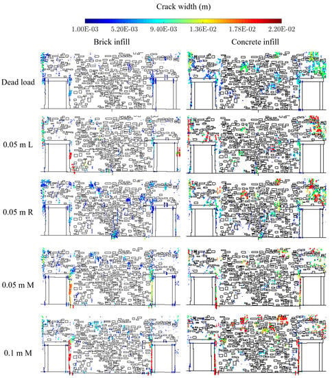
Figure 9.
Crack widths of the existing geometry under combinations of dead load and settlement for brick infill and concrete infill; text value (m) indicates magnitude of settlement, while L, R, and M indicate settlement of left, right, and middle part of the wall, respectively.
Considering just the simulations where the infill is brick, cracking can be seen to occur consistently along the joint with the door frame. This cracking pattern is similar with the qualitative plot of cracks in Figure 5. Aside from the case where there is 0.05 m of settlement of the right side, overall the results are similar in terms of location but very different in terms of magnitude. For instance, in the simulation where there is only dead load versus where there is settlement at the middle 0.1 m, the magnitude of the cracking on the doorway changes from 0.009 m to 0.02 m. Therefore, there is enough difference to qualitatively understand which load cases could have caused the existing crack patterns and which load cases could not have. Comparing the cases where the wall has bricks for infill against the crack map in Figure 5, it can be seen that the simulation with only dead load does not produce cracking of the correct magnitude along the door jams; additionally, the case where there is 0.05 m of settlement on the right side produces too many cracks in the center of the wall’s base which is not evident on the existing wall. Lastly, the cracks in the middle settlement cases match the cracks more than the case where there is settlement of the left side; in the case of the left settlement, cracking does not occur on the right door frame. Therefore, qualitatively considering only the cases where there is brick infill, settlement at the middle of the wall is the most likely reason for the cracks.
With this established, an understanding of how the magnitude of settlement depth could alter the magnitude and location of resulting cracks was desired. Therefore, the wall was settled in the middle section 0.1 m. As can be seen in Figure 9 this does alter the magnitude of the resulting cracks as expected; the 0.05 m M case has less than 1.78 cm of cracking along the leftmost doorway, while the 0.1 m M case has over 2.2 cm. However, it is important to note that while the magnitudes change, most of the locations do not. This illustrates that accurate information about the magnitude of existing cracks is important for understanding the extent of damage mechanism while information about crack location is more important for determining the mechanism itself.
As can be seen from Figure 9, the magnitude and the location of the cracking vary not only with settlement type and magnitude, but also with the material of the infill. Despite the fact that the plots of displacement magnitude were did not show stark differences between the types of infill, it can be seen that the plots of the cracks are sensitive enough to pick that up. The magnitude of the cracking increases with the change in infill material from brick to concrete. One example of this is the case with 0.1 m of settlement in the middle of the wall. With the concrete infill, there is much larger cracking occurring in the middle of the wall’s top section (on the order of 2 cm). On the wall with the brick infill, this cracking was only seen to raise to the order of 0.009 m and additionally on the existing wall, these cracks are very minor. The cracks are able to propagate through the concrete infill much easier than the brick because of the difference in energy required to cause the crack to open. Considering both sets of simulations and the map of existing cracks, it can be qualitatively deduced that the infill material is brick and that the cause of the cracking is settlement of the middle section. An overlay of the results of the simulation and the crack map can be found in Figure 10.
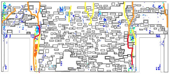
Figure 10.
The results of simulation superimposed on the existing crack pattern.
In pursuing verification for the outcomes of structural analysis according to ISO 13822 [14], it was found that these results make sense in conjunction with the knowledge that a support column under the middle of this wall was removed in 1975 [30]. During removal, it was believed that this column was not load bearing, however the cracks which have become evident suggest otherwise. By understanding the origins of the cracks, a more comprehensive and accurate damage assessment can be made.
8. Conclusions
This study illustrated the importance of integrating non-destructive testing, such as thermal imaging, laser scanning, with numerical modeling for damage assessment through a case study of the Room of Elements. The procedures and techniques described previously have been formalized into a integrative workflow for understanding how existing damages could have originated on a heritage structure (Figure 11). Line-of-sight documentation methods were used to comprehensively document visible aspects of the wall. Laser scanning was used to capture the geometry and boundary conditions of the wall; photogrammetry was used to texture the model and provide deeper insights into the existing crack pattern. High-resolution images were used to augment this information and provide a more detailed view of hair-line cracks not visible in the model. As the wall is covered in a fresco, the exact geometry of the stones as well as any cracks which had not propagated through plaster were not visible. Therefore, non-destructive evaluation in the form of thermal imaging was used to identify damages under the fresco and the geometry of the underlying masonry. By combining the line-of-sight and non-destructive evaluation techniques a map of existing geometry and cracks was generated. However, it was not clear from thermal images whether some of the infill material in the wall was made of brick or concrete. Therefore, the wall was numerically modeled under a variety of loading scenarios (n) for both infill types. Both gravity and settlement loads were considered for this structure based on preliminary comparisons of the laser scan data of the room’s floor to reference planes. By comparing the results of simulation to the existing crack pattern, the material of the infill as well as the most probable scenario which caused the damage was elucidated. In addition to positing the origins of existing damages, this study also highlighted the importance of combining different methods of documentation and numerical simulation for damage assessment.
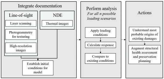
Figure 11.
Workflow for integrating line-of-site documentation, non-destructive evaluation, and numerical modeling for understanding the extent and origins of existing crack patterns.
Author Contributions
Conceptualization, R.N. and M.H.; Data curation, M.H.; Formal analysis, R.N.; Investigation, R.N.; Methodology, R.N.; Resources, M.H.; Supervision, B.G.; Writing—original draft, R.N.; Writing—review & editing, R.N., M.H. and B.G.
Funding
This work was supported by the Department of Civil and Environmental Engineering, the Council on Science and Technology, the Dean’s Fund for Innovation, and the School of Engineering and Applied Sciences at Princeton. Additional support was provided by the Kinsella Fund, the Qualcomm Institute at UC San Diego, the Friends of CISA3, and the World Cultural Heritage Society. This material is based upon work supported by the National Science Foundation Graduate Research Fellowship Program under Grants No. DGE-1656466 and No. DGE-0966375, ‘Training, Research and Education in Engineering for Cultural Heritage Diagnostics’, and award No. CNS-1338192, ‘MRI: Development of Advanced Visualization Instrumentation for the Collaborative Exploration of Big Data’. Any opinions, findings and conclusions or recommendations expressed in this material are those of the authors and do not necessarily reflect the views of the National Science Foundation. Opinions, findings, and conclusions from this study are those of the authors and do not necessarily reflect the opinions of the research sponsors.
Acknowledgments
This work was completed as part of the Itasca Educational Partnership under the mentorship of Jim Hazzard without whose guidance, this paper would not have been possible. Additionally, we are thankful for fruitful conversations with Anna Blyth and Wesley Reinhart.
Conflicts of Interest
The authors declare no conflict of interest.
References
- Baskaran, B. Guideline for Structural Condition Assessment of Existing Buildings; American Society of Civil Engineers: Reston, VA, USA, 1999. [Google Scholar]
- Yung, E.H.; Chan, E.H. Implementation challenges to the adaptive reuse of heritage buildings: Towards the goals of sustainable, low carbon cities. Habitat Int. 2012, 36, 352–361. [Google Scholar] [CrossRef]
- Bullen, P.A. Adaptive reuse and sustainability of commercial buildings. Facilities 2007, 25, 20–31. [Google Scholar] [CrossRef]
- Shipley, R.; Utz, S.; Parsons, M. Does adaptive reuse pay? A study of the business of building renovation in Ontario, Canada. Int. J. Herit. Stud. 2006, 12, 505–520. [Google Scholar] [CrossRef]
- Glisic, B.; Inaudi, D. Fibre Optic Methods for Structural Health Monitoring; John Wiley & Sons: Hoboken, NJ, USA, 2008. [Google Scholar]
- Olsen, M.J. In situ change analysis and monitoring through terrestrial laser scanning. J. Comput. Civ. Eng. 2013, 29, 04014040. [Google Scholar] [CrossRef]
- Pesci, A.; Bonali, E.; Galli, C.; Boschi, E. Laser scanning and digital imaging for the investigation of an ancient building: Palazzo d’Accursio study case (Bologna, Italy). J. Cult. Herit. 2012, 13, 215–220. [Google Scholar] [CrossRef]
- Pesci, A.; Casula, G.; Boschi, E. Laser scanning the Garisenda and Asinelli towers in Bologna (Italy): Detailed deformation patterns of two ancient leaning buildings. J. Cult. Herit. 2011, 12, 117–127. [Google Scholar] [CrossRef]
- Letellier, R.; Eppich, R. Recording, Documentation and Information Management for the Conservation of Heritage Places; Routledge: Abingdon, UK, 2015. [Google Scholar]
- Kadobayashi, R.; Kochi, N.; Otani, H.; Furukawa, R. Comparison and evaluation of laser scanning and photogrammetry and their combined use for digital recording of cultural heritage. Int. Arch. Photogramm. Remote Sens. Spat. Inf. Sci. 2004, 35, 401–406. [Google Scholar]
- Georgopoulos, A.; Ioannidis, C. Photogrammetric and surveying methods for the geometric recording of archaeological monuments. In Proceedings of the FIG Working Week, Athens, Greece, 22–27 May 2004; pp. 22–27. [Google Scholar]
- Bonali, E.; Pesci, A.; Casula, G.; Boschi, E. Deformation of Ancient Buildings inferred by Terrestrial Laser Scanning methodology: The Cantalovo church case study (Northern I taly). Archaeometry 2014, 56, 703–716. [Google Scholar] [CrossRef]
- Napolitano, R.; Hess, M.; Coe-Scharff, R.; Glisic, B. Numerical Modeling of Crack Propagation in Masonry Structures. In Structural Analysis of Historical Constructions; Springer: Berlin, Germany, 2019; pp. 826–834. [Google Scholar]
- International Organization for Standardization. 13822 Bases for Design of Structures-Assessment of Existing Structures; CEN Brussels: Bruxelles, Belgium, 2005. [Google Scholar]
- Carpinteri, A.; Invernizzi, S.; Lacidogna, G. In situ damage assessment and nonlinear modelling of a historical masonry tower. Eng. Struct. 2005, 27, 387–395. [Google Scholar] [CrossRef]
- Meola, C.; Di Maio, R.; Roberti, N.; Carlomagno, G.M. Application of infrared thermography and geophysical methods for defect detection in architectural structures. Eng. Fail. Anal. 2005, 12, 875–892. [Google Scholar] [CrossRef]
- Kilic, G. Using advanced NDT for historic buildings: Towards an integrated multidisciplinary health assessment strategy. J. Cult. Herit. 2015, 16, 526–535. [Google Scholar] [CrossRef]
- Costanzo, A.; Minasi, M.; Casula, G.; Musacchio, M.; Buongiorno, M.F. Combined use of terrestrial laser scanning and IR thermography applied to a historical building. Sensors 2014, 15, 194–213. [Google Scholar] [CrossRef] [PubMed]
- Scaioni, M.; Rosina, E.; L’Erario, A.; Dìaz-Vilariño, L. Integration of infrared thermography and photogrammetric surveying of built landscape. Int. Arch. Photogramm. Remote Sens. Spat. Inf. Sci. 2017, 42, 153–160. [Google Scholar] [CrossRef]
- Wang, C.P.; Huang, Y.; Hsu, S.C.; Hong, J.J. Identifying the Defects Presented on the Exterior Layers of a Structure by Employing 3D Point Clouds and Thermography. In Civil Infrastructures Confronting Severe Weathers and Climate Changes Conference; Springer: Berlin, Germany, 2018; pp. 101–108. [Google Scholar]
- Fais, S.; Cuccuru, F.; Ligas, P.; Casula, G.; Bianchi, M.G. Integrated ultrasonic, laser scanning and petrographical characterisation of carbonate building materials on an architectural structure of a historic building. Bull. Eng. Geol. Environ. 2017, 76, 71–84. [Google Scholar] [CrossRef]
- Lagüela, S.; Solla, M.; Puente, I.; Prego, F.J. Joint use of GPR, IRT and TLS techniques for the integral damage detection in paving. Construct. Build. Mater. 2018, 174, 749–760. [Google Scholar] [CrossRef]
- Huang, Y.; Chiang, C.H.; Hsu, K.T. Combining the 3D model generated from point clouds and thermography to identify the defects presented on the facades of a building. In Nondestructive Characterization and Monitoring of Advanced Materials, Aerospace, Civil Infrastructure, and Transportation XII; SPIE: Denver, CO, USA, 2018; Volume 10599. [Google Scholar]
- Laefer, D.F.; Gannon, J.; Deely, E. Reliability of crack detection methods for baseline condition assessments. J. Infrastruct. Syst. 2010, 16, 129–137. [Google Scholar] [CrossRef]
- Binda, L.; Modena, C.; Casarin, F.; Lorenzoni, F.; Cantini, L.; Munda, S. Emergency actions and investigations on cultural heritage after the L’Aquila earthquake: The case of the Spanish Fortress. Bull. Earthq. Eng. 2011, 9, 105–138. [Google Scholar] [CrossRef]
- Shrestha, S.; Reina Ortiz, M.; Gutland, M.; Napolitano, R.; Morris, I.; Santana Quintero, M.; Erochko, J.; Kawan, S.; Shrestha, R.; Awal, P.; et al. Digital recording and non-destructive techniques for the understanding of structural performance for rehabilitating historic structures at the kathmandu valley after gorkha earthquake 2015. In Proceedings of the ISPRS Annals of the Photogrammetry, Remote Sensing and Spatial Information Sciences, 2017 26th International CIPA Symposium, Ottawa, ON, Canada, 28 August–1 September 2017; Volume IV-2/W2. [Google Scholar] [CrossRef]
- Braganti, F. Florence–Palazzo Vecchio with the Firemen. Available online: https://commons.wikimedia.org/wiki/File:Florence_-_Palazzo_Vecchio_with_the_firemen_2016-11-04.jpg (accessed on 15 August 2017).
- Dei Ministri, P.D.C. Valutazione e Riduzione del Rischio Sismico del Patrimonio Culturale con Riferimento alle Norme Tecniche per le Costruzioni di cui al DM 14 Gennaio 2008; Direttiva PCM: Rome, Italy, 2011. [Google Scholar]
- Hess, M.; Vanoni, D.; Petrovic, V.; Kuester, F. High-resolution thermal imaging methodology for non-destructive evaluation of historic structures. Infrared Phys. Technol. 2015, 73, 219–225. [Google Scholar] [CrossRef]
- Wood, R.L.; Hutchinson, T.C.; Wittich, C.E.; Kuester, F. Characterizing Cracks in the Frescoes of Sala degli Elementi within Florence’s Palazzo Vecchio. In Proceedings of the Euro-Mediterranean Conference, Limassol, Cyprus, 29 October–3 November 2012; Springer: Berlin, Germany, 2012; pp. 776–783. [Google Scholar]
- Quintero, M.; Genechten, B.; Bruyne, M.; Ronald, P.; Hankar, M.; Barnes, S. Theory and practice on terrestrial laser scanning. In Learning Tools for Advanced Three-Dimensional Surveying in Risk Awareness Project (3DRiskMapping); Ed. UPV Univ. Politecnica de Valencia: Valencia, Spain, 2008. [Google Scholar]
- Sapirstein, P. Accurate measurement with photogrammetry at large sites. J. Archaeol. Sci. 2016, 66, 137–145. [Google Scholar] [CrossRef]
- Napolitano, R.K.; Glisic, B. Minimizing the adverse effects of bias and low repeatability precision in photogrammetry software through statistical analysis. J. Cult. Herit. 2018, 31, 46–52. [Google Scholar] [CrossRef]
- Agisoft LLC. Agisoft PhotoScan User Manual: Professional Edition; Agisoft PhotoScan: St. Petersburg, Russia, 2014. [Google Scholar]
- Remondino, F.; Stylianidis, E. 3D Recording, Documentation and Management of Cultural Heritage; Whittles Publishing: Dunbeath, UK, 2016; Volume 2. [Google Scholar]
- Georgiadis, C.; Tsioukas, V.; Sechidis, L.; Stylianidis, E.; Patias, P. Fast and accurate documentation of archaeological sites using in the field photogrammetric techniques. Int. Arch. Photogramm. Remote Sens. 2000, 33, 28–32. [Google Scholar]
- Pepe, M.; Ackermann, S.; Fregonese, L.; Achille, C. 3D Point cloud model color adjustment by combining terrestrial laser scanner and close range photogrammetry datasets. In Proceedings of the ICDH 2016: 18th International Conference on Digital Heritage, London, UK, 24–25 November 2016; Volume 10, pp. 1942–1948. [Google Scholar]
- Cadelano, G.; Bison, P.; Bortolin, A.; Ferrarini, G.; Peron, F.; Girotto, M.; Volinia, M. Monitoring of historical frescoes by timed infrared imaging analysis. Opto-Electron. Rev. 2015, 23, 102–108. [Google Scholar] [CrossRef]
- Kordatos, E.; Exarchos, D.; Stavrakos, C.; Moropoulou, A.; Matikas, T. Infrared thermographic inspection of murals and characterization of degradation in historic monuments. Construct. Build. Mater. 2013, 48, 1261–1265. [Google Scholar] [CrossRef]
- Cotič, P.; Jagličić, Z.; Bosiljkov, V. Validation of non-destructive characterization of the structure and seismic damage propagation of plaster and texture in multi-leaf stone masonry walls of cultural-artistic value. J. Cult. Herit. 2014, 15, 490–498. [Google Scholar] [CrossRef]
- Carlomagno, G.M.; Meola, C. Comparison between thermographic techniques for frescoes NDT. NDT E Int. 2002, 35, 559–565. [Google Scholar] [CrossRef]
- American Society for Testing and Materials (ASTM International). C1153-10 Standard Practice for Location of Wet Insulation in Roofing Systems Using Infrared Imaging; ASTM International: West Conshohocken, PA, USA, 2010; Volume 13. [Google Scholar] [CrossRef]
- Emissivity Values for Common Materials. Available online: http://www.infrared-thermography.com/material-1.htm (accessed on 2 November 2018).
- Psycharis, I.N.; Lemos, J.; Papastamatiou, D.; Zambas, C.; Papantonopoulos, C. Numerical study of the seismic behaviour of a part of the Parthenon Pronaos. Earthq. Eng. Struct. Dyn. 2003, 32, 2063–2084. [Google Scholar] [CrossRef]
- Fang, D.L.; Napolitano, R.K.; Michiels, T.L.; Adriaenssens, S.M. Assessing the stability of unreinforced masonry arches and vaults: A comparison of analytical and numerical strategies. Int. J. Archit. Herit. 2018, 1–15. [Google Scholar] [CrossRef]
- Kavanaugh, C.; Morris, I.M.; Napolitano, R.; Jorquera-Lucerga, J.J. Validating the use of graphical thrust line analysis for pier buttresses: The case study of amiens cathedral. Int. J. Archit. Herit. 2017, 11, 859–870. [Google Scholar] [CrossRef]
- Cundall, P.; Hart, R. Theory and Background: 3DEC 3 Dimensional Distinct Element Code; Technical Report; Itasca Consulting Group: Minneapolis, MN, USA, 2015. [Google Scholar]
- Bui, T.; Limam, A.; Sarhosis, V.; Hjiaj, M. Discrete element modelling of the in-plane and out-of-plane behaviour of dry-joint masonry wall constructions. Eng. Struct. 2017, 136, 277–294. [Google Scholar] [CrossRef]
- Pulatsu, B.; Erdogmus, E.; Lourenço, P.B. Comparison of in-plane and out-of-plane failure modes of masonry arch bridges using discontinuum analysis. Eng. Struct. 2019, 178, 24–36. [Google Scholar] [CrossRef]
- Napolitano, R.; Glisic, B. Methodology for diagnosing crack patterns in masonry structures using photogrammetry and distinct element modeling. Eng. Struct. 2019, 181, 519–528. [Google Scholar] [CrossRef]
- Roca, P. Considerations on the significance of history for the structural analysis of ancient constructions. In Structural Analysis of Historical Constructions IV; Taylor and Francis Group: Amsterdam, The Netherlands, 2004; pp. 63–73. [Google Scholar]
- Clemente, R. Structural Analysis of Historical Buildings by Localized Cracking Models. Ph.D. Thesis, Universitat Politècnica de Catalunya, Barcelona, Spain, 2006. [Google Scholar]
- Asteris, P.G.; Sarhosis, V.; Mohebkhah, A.; Plevris, V.; Papaloizou, L.; Komodromos, P.; Lemos, J.V. Numerical modeling of historic masonry structures. In Handbook of Research on Seismic Assessment and Rehabilitation of Historic Structures; IGI Global: Hershey, PA, USA, 2015; pp. 213–256. [Google Scholar]
- Hess, M. Diagnostic Structural Health Assessment through Layered Integration of Non-destructive Imaging Data. Ph.D. Thesis, University of California, San Diego, CA, USA, 2018. [Google Scholar]
- DeJong, M.J.; Vibert, C. Seismic response of stone masonry spires: Computational and experimental modeling. Eng. Struct. 2012, 40, 566–574. [Google Scholar] [CrossRef]
- Autodesk. Cut, Rough Granite. Available online: https://www.autodesk.com/ (accessed on 10 August 2017).
- Walker, R. Density of Materials. Available online: https://www.simetric.co.uk/si_materials.htm (accessed on 10 August 2017).
- Napolitano, R.; Lansing, L.; Glisic, B. Understanding the Function of Roman Bonding Courses: A Numerical Approach. In Structural Analysis of Masonry Historical Constructions; Springer: Berlin, Germany, 2019; pp. 1798–1806. [Google Scholar]
- Sarhosis, V.; Garrity, S.; Sheng, Y. Influence of brick–mortar interface on the mechanical behaviour of low bond strength masonry brickwork lintels. Eng. Struct. 2015, 88, 1–11. [Google Scholar] [CrossRef]
- Gotti, E.; Oleson, J.; Bottalico, L.; Brandon, C.; Cucitore, R.; Hohlfelder, R. A comparison of the chemical and engineering characteristics of ancient Roman hydraulic concrete with a modern reproduction of Vitruvian hydraulic concrete. Archaeometry 2008, 50, 576–590. [Google Scholar] [CrossRef]
- Reccia, E.; Cazzani, A.; Cecchi, A. FEM-DEM modeling for out-of-plane loaded masonry panels: A limit analysis approach. Open Civ. Eng. J. 2012, 6, 231–238. [Google Scholar] [CrossRef]
- Brune, P.F.; Perucchio, R.; Ingraffea, A.; Jackson, M. The toughness of imperial roman concrete. In Proceedings of the 7th International Conference on Fracture Mechanics of Concrete and Concrete Structures, Seoul, Korea, 23–28 May 2010. [Google Scholar]
© 2019 by the authors. Licensee MDPI, Basel, Switzerland. This article is an open access article distributed under the terms and conditions of the Creative Commons Attribution (CC BY) license (http://creativecommons.org/licenses/by/4.0/).