1. Introduction
Plants require nutrients, such as nitrogen, phosphorus, and potassium, to supplement their growth. While the latter two are obtained from naturally occurring minerals, nitrogen is mainly available in the air as dinitrogen (N
2), the most abundant element in the atmosphere. However, plants find it difficult to absorb N
2 in this form due to its strong triple bond, which makes it less available for direct use. Therefore, it is necessary to find alternative ways of supplying plants with this essential nutrient, and compounds such as ammonia and nitrate are required [
1].
To meet the increasing demand for food production as the global population grows, maximizing and improving land use has become necessary. Ammonia was introduced to supplement food demand by fertilizing plants [
2]. The first method used to mass-produce this substance was invented in 1905 by Fritz Haber, who fixed atmospheric N
2 using H
2 gas under slightly elevated temperatures (450 °C), high pressure (10 MPa), and with the aid of a catalyst. Soon after, Carl Bosch scaled up the process now known as the Haber–Bosch (HB) process, enabling mass production of ammonia. This discovery earned both Haber and Bosch Nobel Prizes in Chemistry, one in 1918 and the other in 1931 [
3].
Currently, approximately 70% of the world’s ammonia production is used for fertilizers, with the remaining percentage being utilized for industrial applications, such as explosives in the mining sector and the production of acrylonitrile, which is used to manufacture plastics, rubber, and fibers. It is also often used as a refrigerant gas [
1,
4]. Due to its numerous applications, ammonia is considered one of the industry’s top 10 most important chemicals. It is often ranked alongside other significant chemicals, such as sulfuric acid, oxygen, nitrogen, ethylene, and chlorine [
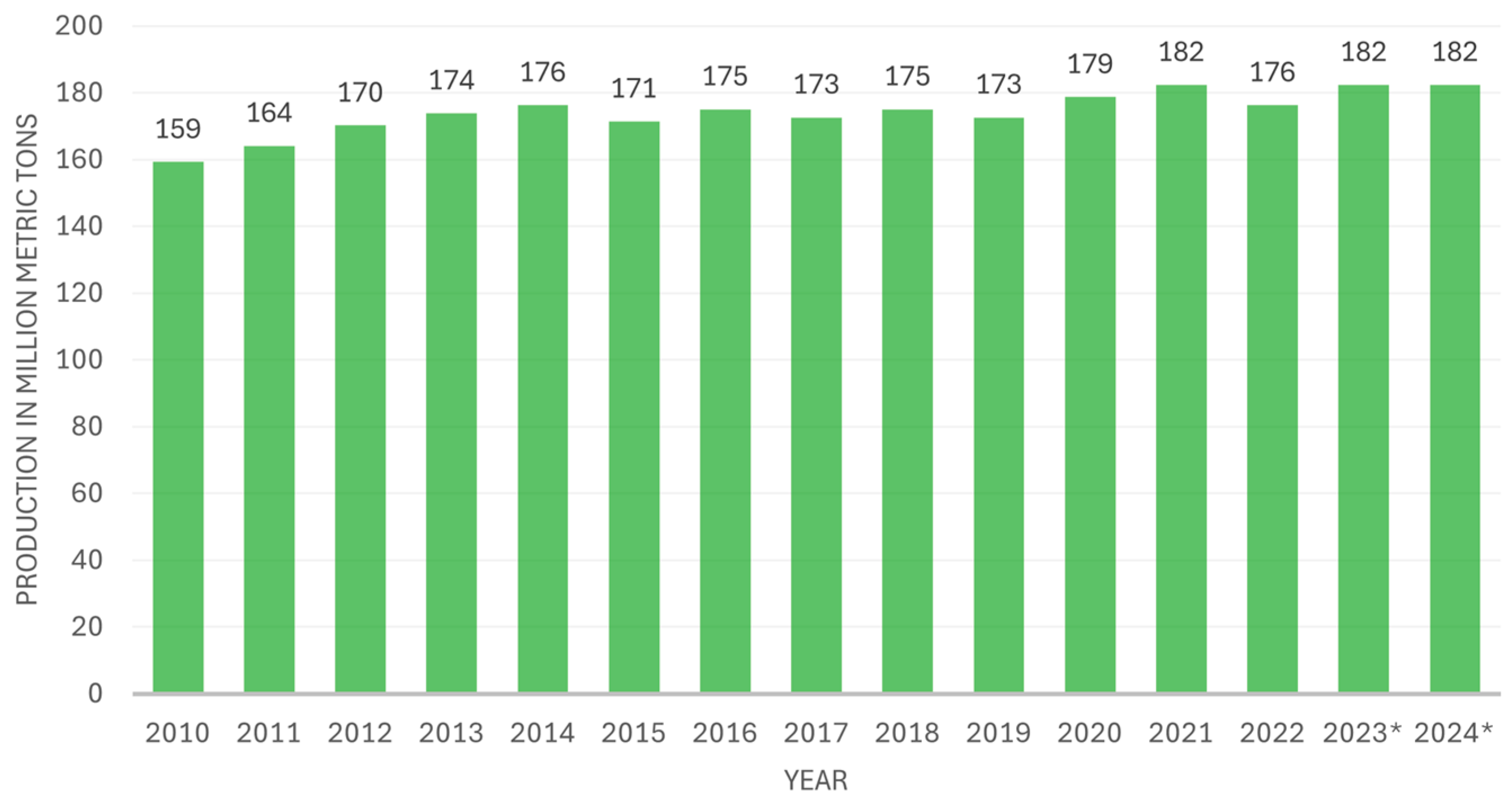
5]. Global ammonia production has remained relatively stable but has experienced overall growth over the last decade, as shown in
Figure 1.
More critical than the volume of ammonia produced is its environmental impact, particularly in terms of greenhouse gas emissions.
Figure 2 presents emissions data from ammonia production alongside other major chemicals for 2015 and 2018, with projections for 2025 and 2030. Notably, in 2015, ammonia production alone generated more emissions than the combined output of methanol and high-value chemicals. Despite this, emissions have been declining and are projected to continue decreasing in the years to come.
Conventional ammonia production relies heavily on fossil fuels and the HB process. In 2021, over 70% of the H
2 used in ammonia synthesis came from natural gas via steam methane reforming (SMR), with the remainder mainly produced through coal gasification, a highly energy- and emissions-intensive process. 2020 global ammonia production accounted for approximately 2% of total final energy consumption and 1.3% of global carbon dioxide (CO
2)-equivalent emissions. China is the largest producer, responsible for around 30% of global output. Other major producers include Russia, the Middle East, the United States, the European Union, and India, each contributing between 8% and 10% [
1].
Ammonia also presents itself as an alternative fuel and energy vector due to its high energy density, adding to the many reasons why we should invest in the green production of ammonia [
8]. It can be used to store energy for further use in electricity generation or as a transport fuel [
9]. Furthermore, a study of Life Cycle Assessment conducted by Bicer and Dincer showed evidence that using ammonia for transportation and power generation can have considerable environmental advantages, mitigating global warming potential [
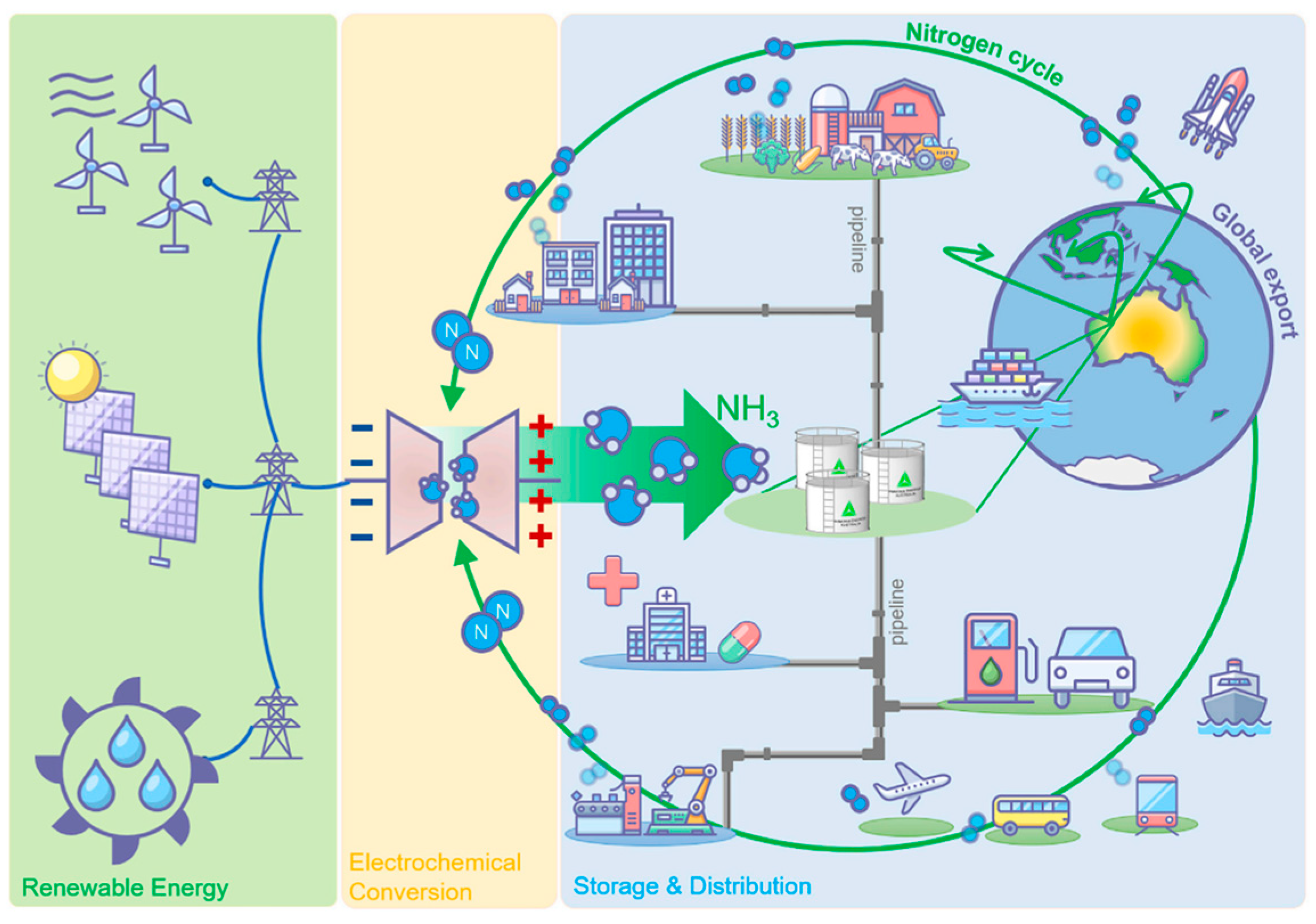
10]. A new ammonia economy has been suggested, given the broad and promising potential of ammonia applications (
Figure 3). This new economy indicates that ammonia is produced solely through electrochemical conversion, utilizing renewable energy sources. It can then be stored, shipped, used as a transportation fuel, utilized for heating purposes, used to produce medication, and applied as a fertilizer.
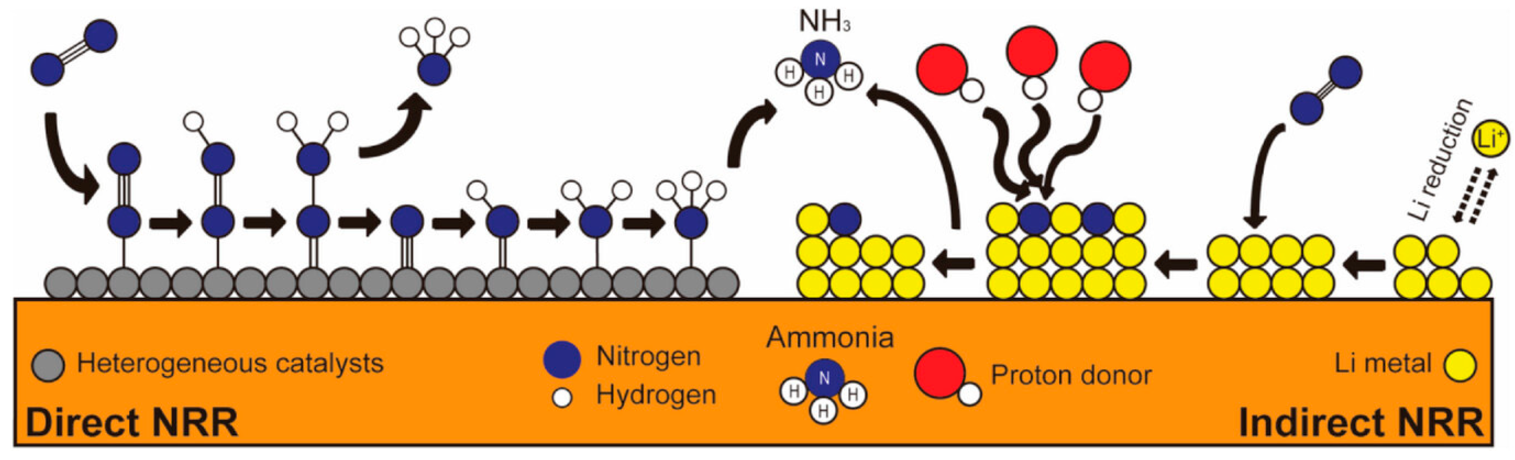
Electrochemical routes for producing ammonia from air and water have been a longstanding scientific challenge. However, they can potentially reduce emissions since they can use electricity generated from renewable sources and do not produce harmful pollutants. These processes are also known as electrochemical nitrogen reduction reactions (eNRRs). They can be separated into direct nitrogen reduction (DNR) and indirect nitrogen reduction (INR), both of which are based on electrochemical processes [
12].
While these methods are being developed and prepared for market entry as competitive technologies, a short-term solution is needed to mitigate climate events and prevent their increasing frequency. The primary emissions issue associated with the HB process is the source of H
2 utilized. Conventional H
2, also known as grey H
2, is produced from fossil fuels, mainly natural gas, through SMR, resulting in significant carbon emissions. To address this issue, a clean source of H
2 is necessary. The growing popularity of H
2 and the projected expansion of its use have established green H
2 production as a viable technology. Green H
2 is generated through the electrolysis of water using renewable electricity. This H
2 can then be utilized in the HB process, resulting in a reduction of up to 88% in emissions, depending on the type of electrolyzer used and the source of electricity. This will also facilitate the integration of locally available renewable energy resources. Water availability is indispensable in this context, as green H
2 production requires high-purity water. This may offer a competitive advantage to countries with abundant water resources compared to those facing arid conditions [
13,
14]. Furthermore, in many developing countries, the demand for fertilizers, particularly nitrogen-based fertilizers, remains high due to growing agricultural needs. Locally produced green ammonia, derived from renewable energy and water, can simultaneously address energy and fertilizer demands, enhancing food security and reducing dependence on imported chemical fertilizers.
This review examines emerging electrochemical methods for ammonia synthesis and compares them to the HB process powered by green H
2, with a focus on techno-economic performance. Following the introduction in
Section 1,
Section 2 outlines the key properties of ammonia and traditional production methods.
Section 3 examines ammonia’s potential role in the future energy landscape.
Section 4 presents the green H
2-based HB process in detail.
Section 5 compares the electrochemical pathways, assessing their operating principles, efficiencies, challenges, and economic viability.
Section 6 discusses future directions and research needs, and
Section 7 concludes with a summary of findings and implications.
2. Ammonia Properties and Production
Ammonia is a colorless gas with a suffocating odor, formed of one nitrogen atom and three hydrogen atoms (NH
3). Its boiling point is −33.4 °C, and its melting point is −77.7 °C at standard pressure and temperature conditions. It is highly irritating at room temperature, alkaline, and corrosive. During transportation, it is typically shipped as a compressed liquid in steel containers [
2,
4]. This is because gaseous ammonia has a lower density than air under atmospheric pressure, facilitating dissipation. Furthermore, the high auto-ignition temperature, approximately 650 °C, also minimizes the risk of explosion in the event of leakage [
15].
Ammonia production requires only two gases: N
2 and H
2. N
2 is collected from the air, whereas H
2 is typically the primary source of the cost and environmental impact of producing ammonia. Equation (1) describes the exothermic reaction for ammonia production, releasing 92.4 kJ mol
−1 [
16].
This reaction can be achieved through several processes, including the Haber–Bosch (HB) process, which is widely recognized for its extensive use. This is the oldest process and a well-established technology that consumes a significant amount of energy, approximately 26 GJ per tonne of ammonia produced. It occurs between 50 and 200 bar and 650 to 750 K in the presence of a catalyst [
17]. Multiple catalysts can be used, the most common being iron with added potassium hydroxide. After leaving the reactor, ammonia is a high-temperature and high-pressure gas that must be liquefied for collection. The N
2 and H
2 that did not react remain as gases at the temperature at which ammonia condenses and can be recycled [
18].
Presently, two critical issues regarding the traditional HB process must be addressed. One is its energy intensity, and the other is the source of H
2 used. As H
2 does not exist alone on Earth, obtaining it requires chemical manipulation. There are several ways to do this. The primary methods are SMR and coal gasification, which generate substantial CO
2 emissions. The SMR process is the most common, producing H
2 from natural gas. It involves two main reactions: a primary reforming reaction, which is endothermic, where methane reacts with steam to produce carbon monoxide (CO) and H
2 (Equation (2)). This reaction is typically followed by the water–gas shift reaction (Equation (3)), where CO reacts with steam to form CO
2 and additional H
2. This exothermic reaction is carried out as a second step to increase the H
2 yield. Thus, the overall reaction for SMR is given by Equation (4), representing the net result of methane reforming followed by the water–gas shift reaction.
Considering a modern, optimized, and highly efficient HB plant fed with methane, its emissions are around 1.5 to 1.6 tonnes of CO
2 equivalent per tonne of ammonia produced (t
CO2 t
NH3−1). The SMR process alone accounts for 1.22 t
CO2 t
NH3−1. The remaining CO
2 emissions relate to the heat supplied to the process, as it is derived from the combustion of a portion of the gas stock. Still, these figures do not even account for the emissions associated with the extraction and transportation of natural gas [
19,
20].
Given the high emissions associated with conventional fossil fuel-based H
2 production methods (i.e., SMR and coal gasification), researchers are increasingly investigating alternative approaches, including the thermocatalytic decomposition of methane. This method has demonstrated the ability to produce H
2 with notably high purity while consuming only half the energy required for SMR. Additionally, it yields solid carbon as a byproduct, thereby eliminating direct CO
2 emissions and providing a more environmentally sustainable pathway. The catalysts used in this process can be metal- or carbon-based; the former are inefficient in the long term due to the rapid loss of activity they undergo, whereas carbon-based solutions have exhibited enhanced stability. Notwithstanding, its potential has not yet been developed on a market scale [
21].
Another thermochemical process is based on chemical looping. In this scenario, direct contact between air and fuel is impeded, thereby preventing the production of CO
2. This looping system transports oxygen via an oxygen carrier between two reactors. The system may comprise more than two reactors, in which reduction and oxidation occur cyclically. These loops can produce H
2 while simultaneously synthesizing ammonia [
22].
Although these methods may offer higher efficiencies, the global shift away from fossil fuel dependence has driven research and development into alternative H
2 production methods, such as water electrolysis, to make them competitive with fossil fuel-based approaches [
23]. This global trend has also extended to ammonia production, where alternative methods and emerging technologies are explored. Ammonia can be categorized into generations or colors, depending on the environmental impact of its production and the type of process used.
Figure 4 illustrates the various types of ammonia, differentiated by color and generation method.
Ammonia produced from the HB process, using H
2 generated from fossil fuels, is classified as grey ammonia. As it is the traditional method of ammonia production, it does not enter the generation classification established for low-carbon ammonia production [
24]. However, if the HB process is coupled with a carbon capture and storage (CCS) system, it is already considered blue ammonia and falls into the 1st generation category. This type of ammonia is regarded as a temporary measure while other technologies are being developed, and the major drawback is the cost of the CCS system [
25]. Green ammonia relies on renewable and sustainable processes, leading to carbon-free ammonia. It can be separated into the 2nd and 3rd generations of ammonia. Second-generation ammonia utilizes the HB process, employing green H
2 instead of H
2 derived from fossil fuels. Some small-scale projects already use this ammonia generation; an example is the case of Siemens, which installed a 20 kW wind turbine to obtain green H
2 using a proton-exchange membrane electrolyzer for subsequent production of green ammonia. This technology has long-term potential but will require significant investments to establish new facilities that involve water electrolysis equipment. It is important to note that this process relies on electricity, and since most renewable energy sources are inherently intermittent, effective energy storage solutions are required [
11,
25].
Third-generation green ammonia involves the electroreduction of the N
2 molecule to ammonia by direct or mediated means. The source of hydrogen is usually water, and the HB process is no longer needed. This generation is still being researched, and multiple options are available, such as the direct electrochemical nitrogen reduction reaction (DNR) and indirect or mediated mechanisms. The first method utilizes an electrocatalyst to promote the direct reduction of the N
2 molecule. The second, also known as the indirect nitrogen reduction (INR) reaction, involves using a mediator, typically a lithium ion, which is first reduced and then utilized to produce ammonia [
11].
3. Ammonia in the Energy Sector
As the world moves towards a green economy, new forms of producing and carrying energy emerge. Liquid ammonia has a high energy density per volume of approximately 15.6 MJ L
−1. This figure represents a 70% increase over the energy density of liquid H
2 (9.1 MJ L
−1 at cryogenic temperatures) and is almost three times higher than that of compressed H
2 (5.6 MJ L
−1 at 70 MPa). On the other hand, energy density per mass is six times lower than that of H
2, which is 142 MJ kg
−1 [
8].
Ammonia is readily liquefied by compression and moderate cooling, making it relatively easy and inexpensive to transport and store, especially when compared with H
2 itself [
8]. With a H
2 content of 17.7% and a higher volumetric density than liquid H
2, ammonia can serve as a compact energy vector. Its high ignition energy also contributes to improved handling safety. These properties make ammonia a compelling candidate as an H
2 carrier.
Building on these intrinsic advantages, ammonia also compares favorably to other H
2 carriers in broader logistical and economic terms. While liquid H
2 has a high gravimetric energy density, its cryogenic storage requirements substantially increase the costs of transport and storage. Liquid organic hydrogen carriers (LOHCs) and synthetic fuels also face economic challenges due to complex processing and high capital and energy costs. In contrast, ammonia is often more cost-effective and logistically feasible, especially at scale. Although H
2 recovery from ammonia cracking requires energy input, this can be mitigated using catalysts such as ruthenium. Green ammonia is often the most economical H
2 carrier for intercontinental transport, delivering energy at a lower cost than LOHCs or synthetic hydrocarbons. It also outperforms liquid H
2 due to reduced infrastructure and liquefaction needs. However, comparative outcomes vary depending on assumptions about energy prices, transport distances, and technology maturity [
26,
27].
Ammonia can be used directly as a fuel in gas turbines, reciprocating engines, and fuel cells. However, these technologies will need to be adapted to this new fuel. This adaptation could be beneficial as it can help reduce emissions, given that ammonia is a carbon-free fuel. It can also enhance the security and reliability of the supply chain because ammonia can be synthesized from elements abundant in nature, nitrogen and hydrogen, and it reduces energy costs due to its ability to serve as an energy storage medium for renewable energy. There are currently few options for energy storage that have achieved commercial maturity. These include compressed air energy storage in underground cavities, pumped hydroelectric storage in dams, and chemical energy storage. The latter has fewer constraints regarding site placement, making chemical storage a viable option for practical energy storage [
8].
Fuel cells have been identified as a potentially viable solution for producing energy through ammonia. The two types of ammonia fuel cells are distinguished as follows: direct ammonia fuel cells are those in which ammonia is used directly in the fuel cell, while indirect ammonia fuel cells are those in which ammonia is decomposed into H
2 before entering the fuel cell. The primary types of fuel cells (FCs) in which ammonia can be utilized to generate electricity, both directly and indirectly, are solid oxide fuel cells, alkaline fuel cells, molten carbonate fuel cells, and proton-exchange membrane fuel cells. These fuel cells have been studied for transportation and small-scale power generation applications. They require further studies to improve performance, cell lifetime, and fuel consumption, which strongly depend on the source of ammonia used. Two of the listed technologies have been demonstrated to be pertinent: the direct ammonia solid oxide fuel cell and the alkaline fuel cell. The operating parameters under consideration are analogous to those of solid oxide electrolysis cells and alkaline water electrolysis. The direct ammonia solid oxide fuel cell can be divided into two categories, depending on the conductive ion: an oxygen ion or a proton. For the transportation sector, it represents a promising solution. A 60.6 L fuel tank of ammonia can provide a driving range of 756 km. This is almost twice the range of the same volume of liquid H
2 (417 km) and three times the range of the same volume of compressed H
2 (254 km) [
8,
28,
29].
Ammonia can be used in internal combustion engines (ICEs); however, due to its low flame speed and high resistance to auto-ignition, it must be blended with other fuels and cannot account for more than 80% of the power produced by a gasoline engine. It can be combined in a combustion engine with other fuels such as gasoline, H
2, and natural gas [
30]. Additionally, the high latent heat of vaporization of ammonia, which is nearly five times greater than gasoline, may lower the temperature, potentially leading to incomplete fuel combustion and a loss of engine efficiency [
16]. A mixture of ammonia with 20% H
2 was trialed in spark engines, resulting in enhanced stability and performance comparable to conventional fuels. The mixture of equal parts of ammonia and natural gas led to an 18–28% reduction in CO
2 emissions compared to using natural gas alone [
31].
In gas turbine technology, ammonia has been tested in a study conducted by Valera-Medina [
32] in combination with methane and H
2. This study showed that stable flames and low emissions can be achieved with both blends [
32]. The utilization of ammonia in combined cycle gas turbines has the potential to represent a pivotal solution for the electricity market. In the context of an expanding renewable energy sector, there is an increasing imperative to incorporate dispatchable green electricity to phase out existing fossil fuel electricity generation facilities. By 2040, the available evidence suggests that this solution will be economically and technically viable. Nevertheless, the viability of this proposal is contingent on several factors, including the cost of electrolyzers for H
2 production (used for green ammonia production), capital costs, and progress in renewable energy [
33]. However, some concerns must be addressed, such as the low chemical reactivity of ammonia and the emissions of NO
x. The same problem of low flame speed and the high minimum ignition energy in combustion in ICEs leads to low efficiency when using ammonia alone [
34].
There are numerous possibilities for utilizing this substance in the energy sector, ranging from fuel to storage solutions. However, when it comes to ammonia combustion, the low-speed flame and NOx emissions are two roadblocks that prevent its use as a standalone fuel. The use of ammonia as an H2 carrier can address the issue of H2 storage, and it is a promising solution for various technologies, including fuel cells.
4. Haber–Bosch Process Using Green Hydrogen
As previously stated, second-generation green ammonia represents a method that employs the conventional production process of ammonia, the Haber–Bosch (HB) process, but with H
2 derived from clean sources. This approach means the optimal solution for expedient adaptation. It entails integrating electrolyzers within the plant, in conjunction with incorporating renewable energy, to ensure that the source of electricity is green and not a mixture, as typically found on the grid.
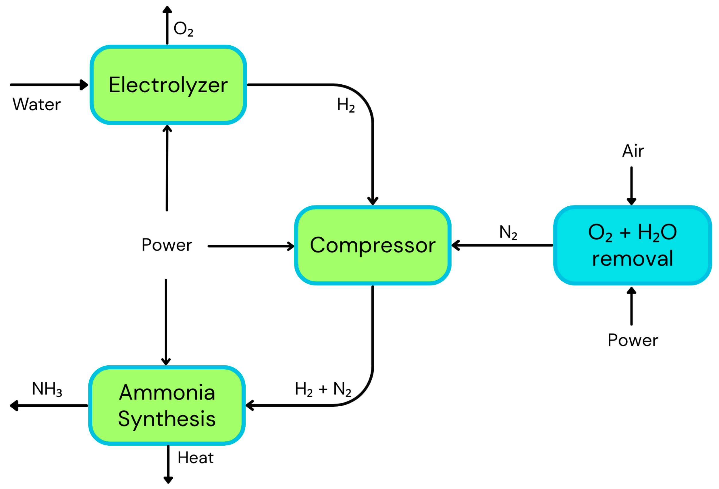
Figure 5 illustrates a simplified schematic of an HB plant for producing green ammonia. The major change to the conventional HB process is the H
2 production method, which is replaced by electrolysis; all other aspects remain the same as with grey ammonia.
Conventional ammonia production infrastructures utilize the heat generated by the SMR process to feed the HB process. However, with the replacement of the SMR infrastructure for electrolyzers, a new heat source is required. Furthermore, the HB process is not particularly flexible, resulting in complications when adjusting operating conditions to maintain a constant H
2 flow rate. It must be acknowledged that the energy sources used to produce H
2 are intermittent. Therefore, there is a need to develop a means of storing energy to maintain a continuous H
2 production process or even to store H
2 itself as a means of compensating for this shortcoming [
35].
Furthermore, this technology is already in its implementation stage. A consortium comprising Madoqua, Power2X, and Copenhagen Infrastructure Partners is developing a project to produce green H
2 and ammonia on the Portuguese coast, specifically in the Sines region. This project will install 1.2 GW of electrolysis capacity, leveraging Portugal’s renewable energy portfolio. In the first phase, 500 MW of capacity will be installed, and the H
2 produced will be utilized either for ammonia production or by other companies within the industrial zone. This capacity will enable the production of 51,000 tonnes of green H
2 and 300,000 tonnes of green ammonia annually. In the second phase, yearly production is expected to increase to 150,000 tonnes of green H
2 and 1,000,000 tonnes of green ammonia. These figures will require a total investment of approximately USD 2.8 billion, creating around 265 direct jobs (and over 6000 indirect jobs) and contributing to Portugal’s National Hydrogen Strategy (EN-H2).
Figure 6 represents the envisioned appearance of the Sines Industrial Zone upon project completion [
36].
4.1. Electrolysis Technologies Coupled with Green Ammonia Production
H
2 production via electrolysis can be achieved using several technologies, with the two main commercial types being the alkaline water electrolyzer (AWE) and the proton-exchange membrane (PEM) electrolyzer. As of 2023, AWE remains the dominant technology, accounting for over half of the global market share. PEM electrolyzers account for approximately 40% of the total and are rapidly gaining ground due to their higher efficiency and better integration with renewable energy sources [
37]. Solid oxide electrolysis cells (SOEC) and anion-exchange membrane (AEM) electrolyzers are also gaining traction, though they still represent a small market share. These four technologies differ significantly in operating temperature, pressure, and the materials used, including electrodes and electrolytes, making it essential to carefully select the appropriate type when designing a production plant.
4.1.1. Alkaline Water Electrolyzer
As the most established H2 production technology, alkaline water electrolysis is widely adopted in industrial applications. Since production costs are low and the materials used as catalysts are non-precious, it makes it an economically viable option for large-scale H2 production. However, the system utilizes corrosive liquid electrolytes, requiring careful handling and maintenance. Traditionally, the separators used asbestos, which poses environmental and health hazards. Due to continuous research, new and better separators are now available. Furthermore, AWE operates at lower current densities and has a slower dynamic response than PEM electrolyzers, making it less efficient for applications with rapid fluctuations.
Alkaline water electrolyzers use an alkaline solution as the electrolyte, either NaOH or KOH. They have two electrodes: the anode, typically made of nickel, cobalt, or iron, and the cathode, usually made of nickel [
38]. The catalysts present one of the advantages of using this type of electrolyzer, as they are very cost-effective [
39].
Figure 7a illustrates a schematic representation of this electrolyzer and the reactions in each compartment.
They work at low temperatures (60–90 °C) and low to medium pressures (1–30 bar). The efficiency of this electrolyzer is approximately 65–70%, and the energy consumption is around 29–46 GJ t
NH3−1. The capital cost of installation is lower than that of PEM electrolyzer, ranging from USD 170,000 to USD 490,000 t
NH3−1, and is expected to decrease to USD 70,000–USD 245,000 t
NH3−1 in the long term. The stack lifetime is similar to that of the PEM electrolyzer, with a range of 60,000 to 90,000 h, and is expected to increase to the same figure as the PEM electrolyzer [
40].
4.1.2. Proton-Exchange Membrane (PEM) Electrolyzer
PEM electrolyzers have a good technology readiness level (TRL) of around 8–9. They work at low temperatures (30–100 °C) and high pressures (10–200 bar). This electrolyzer consists of two electrodes: the anode, typically comprising iridium oxide as an electrocatalyst for the oxygen evolution reaction (OER), and the cathode, containing a platinum-based electrocatalyst for the hydrogen evolution reaction (HER). The electrolyte is typically composed of Nafion, a solid polymer electrolyte membrane that only allows protons to pass through, which is why the electrolyzer is named after it.
Figure 7b illustrates the schematic of an electrolyzer of this type and the reactions occurring at the cathode and anode.
The efficiency of a PEM electrolyzer is approximately 80–90%, and the energy consumption is around 31–46 GJ t
NH3−1. This type of electrolyzer is more adapted to be powered by renewable energy than other electrolyzer types. It features an optimized ohmic drop characterized by a compact design that enables high current densities [
39]. The stack’s lifetime is projected to increase from 30,000 to 90,000 h to 100,000–150,000 h in the long term (beyond 20 years). Assuming the use of PEM electrolyzers for green H
2 production, the installed capital cost per tonne of annual production capacity for green ammonia plants ranged between USD 365,000 and USD 630,000 in 2020, and in the long term, it is expected to decrease to USD 70,000–315,000 [
40].
PEM electrolysis represents a more advanced and responsive technology, allowing for compact, safe, and modular design capable of operating at high current densities and, therefore, having higher efficiency. Despite its advantages, it also faces several key challenges, including reliance on expensive, novel metal catalysts such as platinum and iridium. Additionally, the acidic operating environment limits the range of compatible materials and accelerates membrane degradation.
4.1.3. Solid Oxide Electrolysis Cell
Depending on the type of ion transported within the electrolyte, these electrolyzers can be characterized into oxygen ion-conducting SOEC (O-SOEC) and proton-conducting SOEC (H-SOEC). Since oxygen ions have low ionic conductivity at lower temperatures, O-SOEC operates at high temperatures, ranging from 600 to 1000 °C. The electrolyte is typically yttria-stabilized zirconia (YSZ), a good conductor of oxide ions (O
2−) at high temperatures. The cathode is usually nickel–YSZ, and the anode is composed of lanthanum strontium manganate. It is the most common type of SOEC. Proton-conducting electrolytes require less activation energy and therefore operate at lower temperatures. The H
2 produced through H-SOEC has higher purity [
41,
42].
Figure 7c presents representations of both H-SOEC and O-SOEC.
These technologies are ideal for continuous operation and will be damaged quickly if not operated in this manner, since they have longer startup and shutdown times. The operating pressure is low to medium (1–25 bar) and has an efficiency of 90–100%, making it the most efficient technology. The energy consumption is approximately 25 GJ t
NH3−1. However, due to the high operation temperature, the stack lifetime is also reduced by degradation, with an estimated range of 10,000 to 30,000 h. This figure is expected to increase from 75,000 to 100,000 h in the long term. This degradation rate is critically important, and efforts are underway to reduce it by developing and implementing new materials. Furthermore, it has the highest installed capital cost of all electrolyzer technologies, approximately USD 980,000 to USD 1,960,000 t
NH3−1, with this figure expected to decrease to about USD 175,000 to USD 350,000 t
NH3−1 [
40,
43].
The high temperature in O-SOEC enables the utilization of thermal energy, such as industrial waste heat, which significantly reduces the overall energy input for H
2 production. However, this high temperature also complicates system design, leading to high material costs and an increased risk of thermal degradation, which affects system durability and reliability. This technology must still mature before it can be implemented in industrial applications [
42].
4.1.4. Anion-Exchange Membrane (AEM) Electrolyzer
The AEM electrolyzer combines advantages from both AWE and PEM electrolyzer technologies. However, it remains the least mature of the four and is not commercially available for industrial-scale applications. AEM electrolyzers operate in an alkaline environment maintained by a dilute KOH solution that enables the use of cost-effective catalysts typical of AWE systems, while also achieving high current densities and operational flexibility comparable to PEM electrolyzers [
44].
Operating temperatures for AEM electrolyzers typically range from 30 to 80 °C, with pressures around 30 bar. Current densities can reach up to 500 mA cm−2. Due to the alkaline environment, these systems can employ non-precious metal catalysts on both electrodes. Nickel-based materials are commonly used at the cathode for H2 evolution, while the anode typically utilizes nickel-iron or cobalt-based catalysts for oxygen evolution. AEM electrolyzers have demonstrated lower energy consumption in small-scale and laboratory settings than PEM and AWE systems.
While still in the research and development stage, AEM electrolysis technology faces several challenges, including membrane degradation, voltage losses, and catalyst performance and loading. As an early-stage technology, AEM electrolysis has not been widely studied for ammonia production, and data on its integration remain limited.
Figure 7d presents a schematic representation of this type of electrolyzer [
44].
4.2. Environmental Considerations
Utilizing renewable energy for the electrically driven HB process significantly reduces CO
2 emissions. Considering the value of the carbon footprint associated with wind power generation in the UK, which produces 50 g CO
2eq kWh
−1 for a small wind park installation and 11.2 g CO
2eq kWh
−1 for a large wind park installation. A plant that requires 38.2 GJ t
NH3−1, when operating with wind energy, can produce ammonia with a carbon intensity of 0.12 to 0.53 t
CO2 t
NH3−1, representing a decrease of three to eight times compared to conventional plants using SMR [
19].
The best available technologies for HB using electrolysis have a carbon footprint of around 0.1 t
CO2 t
NH3−1, while the potential of this technology using electrolysis can help eliminate greenhouse gas emissions. On the other hand, grey ammonia has reached its maximum reduction in greenhouse gas emissions. It is impossible to reduce the emissions of the best available technology (1.6 t
CO2 t
NH3−1) unless a CCS system is coupled to the plant. In that case, the best available technology can reduce emissions up to 0.4 t
CO2 t
NH3−1, while the potential of this technology might be able to reduce them to 0.2 t
CO2 t
NH3−1 [
40].
The electrochemical production of ammonia is also not free of emissions, not due to the process itself but rather due to the materials and substances required. For the indirect method, or lithium-mediated pathway, the brine refining to concentrate lithium hydroxide accounts for significant emissions. When combined with electricity emissions, accounting for a weight of fossil fuels in electricity production of 63%, the emissions related to this process can increase to 3.5 t
CO2 t
NH3−1 [
45].
4.3. Energy Considerations
The efficiency of the process increased significantly from the 1970s to the late 1990s; however, since then, progress in efficiency has been minimal. The efficiency of the process can then be compared to that of HB using green H
2, as shown in
Figure 8. The data for the electrically driven process is extrapolated from the methane-fed process, utilizing more efficient compressors and the typical efficiencies for current alkaline and PEM electrolyzers (60%). In addition to the projected availability of efficient PEM electrolyzers (75%) and solid oxide electrolyzers (80%) in the medium term, the data include a hypothetical 90% efficient electrolyzer and a low-pressure (3 bar) HB process with in situ ammonia absorption.
Figure 8 also indicates the TRL of the combination of methods that can be used, focusing on alkaline and PEM electrolysis. Nevertheless, these technologies have the most significant losses associated with the electrolysis process. An HB plant is usually designed to operate 24 h a day, seven days a week, to produce ammonia. The minimum power requirement for this is between 28 and 44 MW. However, if the plant is converted to produce green H
2 with alkaline electrolyzers, the power requirement increases by more than 300 MW. This is necessary to operate the plant for the same number of hours and produce the same amount of ammonia [
35].
Another study indicates that HB using SMR has an energy requirement of 26 GJ t
NH3−1, despite being already optimized to its minimum energy consumption. The best available technology of green ammonia production in 2020 presented a consumption of 33 GJ t
NH3−1, and the potential for 2050 is to reduce this figure to 26 GJ t
NH3−1 using high-temperature electrolysis and 31 GJ t
NH3−1 using low-temperature electrolysis [
40].
4.4. Economic Considerations
Regarding capital expenditure (CAPEX) for a conventional ammonia plant, the figure is approximately USD 183 million. In contrast, for a green H
2 plant of the same type as the one above, the CAPEX increases almost threefold to USD 483 million. This indicates that the CAPEX of producing ammonia with green H
2 is highly dependent on the cost of producing green H
2, which varies according to the type of electrolyzer and electricity prices. However, both the costs of renewable electricity and electrolyzers are decreasing [
35].
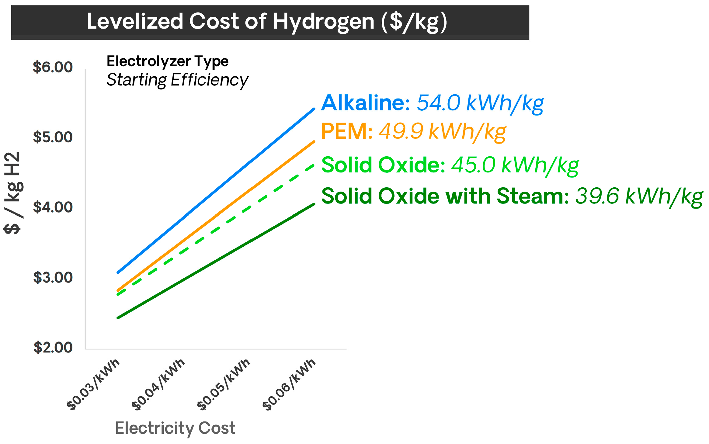
Figure 9 shows that SOECs are the type of electrolyzers that offer a lower levelized cost of hydrogen (LCOH).
A techno-economic analysis of a green ammonia production plant in Chile was conducted in 2023 by Fúnez Guerra et al. [
17]. In their study, a Siemens electrolyzer with a total capacity of 160 MW was considered, along with the transportation of ammonia to Japan. In addition to these considerations, the study also examined other factors, including yearly operating time, investment costs, electricity expenses, staff salaries, gross water usage, land leasing fees, transportation costs, the weighted average cost of capital, inflation rates, and ammonia sales costs. Furthermore, a
ceteris paribus study was conducted, which involved analyzing the Payback Period (PBP) and the Net Present Value (NPV). It was determined that the electricity price must be below a certain threshold for the project to be financially viable. In this case, the threshold was set at USD 27 MWh
−1. The operating hours must also be maximized for the net present value (NPV) to be positive. This threshold was set at 3700 h per year. The capacity of the electrolyzer is something else that should be considered. Following their study, the plant should have a capacity higher than 50 MW to be economically viable. Regarding the PBP, its value is influenced by the ammonia price at the point of delivery. In this case, Japan was the destination. It was evident that, for prices below USD 420 t
NH3−1, the PBP exhibited an exponential increase, making it challenging for companies and investors to make clear decisions. The variation in the PBP based on the HB cycle cost is employed in a sensitivity analysis, given that this equipment and the electrolyzer represent the higher costs.
To achieve a PBP of less than ten years, the ammonia sales price should not exceed USD 430 t
NH3−1, according to
Figure S1, which can be found in the
Supplementary Information. For the same PBP, the cost of the HB process should be lower than USD 660 kW
−1, and the electrolyzer cost should be below USD 650 kW
−1, as shown in
Figures S2 and S3. It should be noted that for electrolyzer costs higher than USD 840 kW
−1, the PBP increased at a higher rate, which should be presented as the maximum cost. The net present value exhibits a positive linear relationship with the ammonia facility size and annual operating hours and a negative linear relationship with electricity costs, as illustrated in
Figures S4–S6, respectively. Following this a priori analysis, optimizing all the results with the appropriate software is possible, thereby providing the company with all the essential information required to make an informed decision.
Hochman et al. estimated the costs of producing ammonia with H
2 from a PEM electrolyzer with a capacity of 50 t
H2 day
−1 and an electricity cost of USD 49 MWh
−1 [
47]. For a large HB plant with a capacity of 2000 t
NH3 day
−1, the total cost was approximately USD 630 t
NH3−1. This value is based on the following factors: electricity to produce H
2, with 80% electrical efficiency; capital cost of the electrolyzer; operation and maintenance expenses of the electrolyzer; electricity for the HB process; capital cost of the HB plant and the air separation unit for N
2 production; and the operation and maintenance expenses for the HB plant. The higher portion of the cost is attributed to the electricity required to produce H
2, once again underscoring that the cost of electricity determines the overall price [
47].
Gomez and Garzon demonstrated that ammonia production using the HB process and PEM electrolysis for H
2 production has an energy consumption of 29.7 MWh t
NH3−1 and an electricity cost of USD 297 t
NH3−1. CAPEX and OPEX were estimated to be USD 627 t
NH3−1 and USD 157 t
NH3−1, respectively, and the final ammonia cost was USD 975 t
NH3−1 [
45].
4.5. Use of Renewable Energy
The primary challenge that will persist is the variability and intermittency of renewable energy. To mitigate the impact of variability, the plant must be adapted, and models and simulations can help predict and identify the optimal behavior for the plant.
Figure 10 illustrates two potential scenarios for ammonia production utilizing solar-driven electrolysis.
In the first scenario, ammonia production is maintained at a constant level, with H
2 production during peak months compensating for the deficit in H
2 production during the low-energy months of the year. This scenario assumes the necessity for seasonal H
2 storage, which would increase capital expenditure. In the second scenario, ammonia production is adjusted in response to H
2 production. This layout will decrease ammonia production during the cold months, denying the need for seasonal storage [
35].
Due to the electrolyzers’ operational conditions, only the PEM electrolyzer is adapted to function under intermittent energy sources. Given this constraint and SOEC’s higher efficiency, some might suggest implementing a PEM electrolyzer combined with SOEC. This would allow the plant to incorporate renewable energy while maintaining a constant H
2 production rate [
46].
6. Future Prospects
Ammonia production will take on a different form to meet the diverse potential applications of the future. The decentralized production of ammonia to meet demand will become a reality. There are already cases of this in practice. In Kenya, near Nairobi, a small fertilizer plant utilizes a solar plant installed on-site to produce green H
2, which is then used to produce approximately one tonne of ammonia per day. This trend is expected to become increasingly prevalent as we move forward [
6].
Regarding the Haber–Bosch process using green H
2, some potential advances are still to be made. Namely, minimizing the costs of green H
2 involves reducing the cost of electrolyzers and electricity, as well as increasing the efficiency of electrolyzers. The HB also consumes a significant amount of energy due to its temperature and pressure requirements, and reducing both would lead to energy savings. This improvement can essentially be achieved by enhancing the performance of catalysts. Modeling and simulating the HB process will also help decentralize the production [
13].
In the context of DNR, it is crucial to reduce the high overpotentials required for activation by enhancing the catalyst’s performance, leading to faster reaction rates. Additionally, the FE should be optimized by suppressing the HER until it reaches 90%, and the overall energy efficiency should be increased to 60%. Another significant improvement will be the solubility of N
2 gas in water, facilitated by advances in electrolyte and gas diffusion electrodes. As ammonia production necessitates continuous operation over extended periods, enhancing the catalyst’s longevity, efficiency, and selectivity is imperative. Recent studies have indicated that the current longevity is less than 100 h, and many often favor HER over eNRR. Manipulating temperature, plasma, and pressure can also enhance reaction rates, FE, and N
2 solubility, respectively. Scaling up both routes of eNRR and integrating them with intermittent renewable energy sources poses technical and economic challenges that will take time to overcome [
13,
55].
In addition to the above factors, government incentives and legislation will facilitate the transition to a green ammonia future. However, to reduce the price of green ammonia, it is essential to reduce the cost of electricity and invest in renewable energy sources, which currently offer the lowest market price for electricity production. Consequently, green ammonia production is anticipated to be driven by the development and implementation of renewable energy sources, such as wind and solar [
56].
The requirement to utilize pure water for electrolyzers hinders arid countries from producing green ammonia at competitive costs. Thus, a fair market must be established between countries to provide all the ammonia necessary for those unable to produce it. The water purification step can also be limiting as the demand increases, and effort should be put into studying water availability and purification [
56].
Furthermore, beyond the viability of available technologies, it is crucial to consider the broader integration and optimization of the ammonia value chain. Transportation is a critical component. Galimova et al. found that importing ammonia from Morocco to Spain via pipelines is currently less economically viable than shipping by sea from Chile or Morocco, or producing it domestically; this suggests that future ammonia trade flows may hinge on maritime access [
57]. However, repurposing existing ammonia pipelines presents a significant opportunity for infrastructure sharing, as it lowers capital investment requirements and accelerates deployment timelines. Renovation of existing pipeline infrastructure could support fertilizer distribution and H
2 transport, enabling a more cohesive energy-fertilizer nexus.
The contemporary energy landscape presents a unique set of challenges and opportunities. Green ammonia represents a promising avenue for decarbonization, with cross-sectoral applications as an H
2 carrier, a fuel for power generation, and an agricultural input. In many developing regions, where fertilizer demand is rising in tandem with population growth, locally produced green ammonia could reduce dependence on imports while promoting energy independence. The synergies between the hydrogen economy, fertilizer systems, and the power sector can be harnessed more effectively through shared production, storage, and distribution infrastructure. Particularly for distributed or on-site production models, retrofitting and adapting existing ammonia transportation and storage systems will be essential [
55,
56]. Coordinated infrastructure planning can thus unlock significant economic and operational efficiencies across the entire ammonia economy industrial chain.
In addition to the ammonia production methods discussed in this work, other emerging approaches utilize both chemical and electrochemical reactions, primarily operating at ambient temperature and pressure. These advances promise to enable decentralized ammonia production, which could complement centralized systems and further enhance the flexibility and resilience of the ammonia economy. For example, a French startup, Swan-H, is developing a chemical/electrochemical method for on-demand ammonia production. Their process is less energy-intensive and features a primary reaction independent of contact with the electrode surface, thereby opening the possibility of higher production rates. The TRL for this project was four in 2023, which was expected to increase [
58].
7. Conclusions
Ammonia production will continue to play a significant role in the future economy. Therefore, it would be prudent to consider ways of adapting production to meet demand and the likely scenario for the foreseeable future.
In a preliminary approach, given the climate emergency scenario we are facing, it is necessary to adapt conventional Haber–Bosch plants to produce clean H2 for use in the process. This transformation will come with the cost of purchasing the electrolyzers and fluctuations in electricity costs. It is possible to bypass this challenge by installing a renewable power plant, such as a solar or wind farm, that produces electricity exclusively for this purpose. However, the Haber–Bosch process lacks flexibility in accommodating variable feedstock supply, which poses a challenge when integrating it with renewable energy sources known for their intermittency. To address this, either energy storage systems must be coupled with the renewable energy plant, or electricity must be supplemented from the grid during periods of low renewable generation. The choice of electrolyzer technology for H2 production in a green ammonia system depends significantly on the nature of the electricity supply. If grid electricity ensures continuous operation, SOECs are the most suitable due to their high efficiency under steady-state conditions. Conversely, PEM electrolyzers are more appropriate if the system is designed to operate primarily on renewable electricity, owing to their superior operational flexibility and fast response to power fluctuations. A hybrid approach—combining SOECs for steady grid-powered operation with PEM electrolyzers to capture intermittent renewable output—may offer an optimal solution, leveraging both high efficiency and flexibility. This shift to green H2 will reduce CO2 emissions from 1.6 tCO2 tNH3−1 to 0.1 tCO2 tNH3−1, while maintaining energy consumption at approximately the same level, using high-temperature electrolyzers. An economic analysis is crucial for optimizing the net present value and the payback period of the project, as well as other important economic factors. For this step, multiple software options are available to simulate various scenarios. Nevertheless, many studies have shown that this transition requires a particular investment, but with sufficiently lower electricity prices, it becomes economically viable.
In a second approach, it may be interesting to examine various technologies. Electrochemical routes for ammonia production are gaining popularity but are still in the early stages of development, and neither has been tested on a large-scale production yet. Direct nitrogen reduction (DNR) still faces challenges, such as the HER competing with the primary reaction. DNR advancements depend on finding suitable and improved catalysts with higher selectivity that will lower the overpotential. On the other hand, indirect nitrogen reduction still needs to overcome one of its limiting factors, which is the potential required for the lithium layer to form on the electrode. However, it is an exciting approach that already has high Faradaic efficiency. The engineer of the SEI layer and the effectiveness in proton delivery will be pivotal to achieving higher overall energy efficiencies. But overall, it is a method that has proven to be economically attractive.
In summary, utilizing green H2 in the Haber–Bosch process represents the initial and most immediate step in transitioning toward sustainable ammonia production. In the long term, as electrochemical nitrogen reduction technologies become economically viable, they will offer a more comprehensive solution, enabling a full transition and nearly complete elimination of greenhouse gas emissions.


