1. Introduction
Different cooking mechanisms are used all over the world and have substantially different mechanisms depending on the user’s preferences [
1]. Within developing countries and other regions with a less advanced infrastructure, many people cook with solid fuels as opposed to gas, oil, or electricity (if available) [
2,
3]. These solid fuels pose issues and health concerns for the people using them. One of the major health concerns is that of volatile pollution from the fuel being used, in most cases biofuels such as wood, crop residue, or in some cases animal dung [
4,
5]. Numerous methods of cooking have been utilized over the years to improve efficiency of the cooking process. Some of these methods include open flame fires, three brick fires (TBF), and eventually cookstoves [
6]. The TBF is an adaptation of the open flame fires—the most basic structure to build around combustion also proves to be most problematic to the users. These TBFs and open flame fires offer little to no directional concentration of heat as cross winds and other environmental aspects can vary the location and temperature of the flame at any given time since it is open to the atmosphere. These cooking mechanisms also yield high quantity of particulate matter, which get released into the environment and can be very harmful to the users [
7]. Another method of cooking is a rocket stove, which is more efficient than the TBF and the open flame fires and has a much lower emission of volatiles [
8]. The major benefit of these early and basic cooking mechanisms is the ease of adding fuel to them [
9]. TBF and open flame fires are open to the environments so that fuel can be quickly placed on the already burning fuel. Rocket stoves offer the fuel input as an opening near the bottom of the stove to insert fuel. Some of the advantages and disadvantages are outlined in
Figure 1.
There are many other types of gasifier cookstoves that have been proposed and used throughout the world [
6]. The cookstove of interest for this design is the top-lit-up-draft (TLUD) stove. TLUD stoves attempt to utilize a more efficient combustion method by burning gasses as opposed to solid fuels via a thermochemical reaction called either pyrolysis or gasification. When the biomass fuel is heated within a limited oxygen environment, the solids break down into carbon-concentrated biochar and their volatile gasses mix with the limited oxygen available creating a combustible syngas typically made of CO and hydrocarbons that is able to be burned for heat [
6]. As this gas mixture burns, it is much cleaner than that of direct combustion of the solid forms of biofuel, which could release the carbon into the air in a solid, aerosol form of particulate matter.
TLUD stoves are one of the more basic cookstoves to be fabricated in the sense that there is no need for forced air via fan or blower to allow for gasification to take place [
10]. Improved cookstove designs suggest changes to airflow that increase heat transfer efficiency, but still utilize only a batch system for initial fuel feeding [
11]. Furthermore, this and similar studies focus on the laboratory testing methodologies rather than the operational elements that will drive acceptance by end users [
12,
13]. Fortunately, TLUD stoves can often be made by indigenous materials, which also can help in material sourcing. Generally, the heat created is more concentrated as opposed to an open fire due to the enclosed cookstove system directing the heat up and out. This offers a more efficient heating method than an open fire or three brick fire since the heat is not being lost in multiple directions and is more controllable.
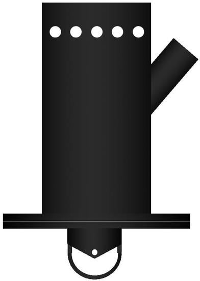
One of the biggest issues with the cookstove, though, is the inability to safely and effectively add fuel to the system once the stove begins firing and having multiple regions to cook at different temperatures [
14]. The right image of
Figure 1 shows a TLUD example where no fuel port is available to continue feeding the combustion process nor an option to move to lower temperature locations. Fuel cannot be added in through the top of the burning stove as it could combust and start the coal-bed on fire and cause a high volume of volatiles and particulate matter to be introduced into the air. The stove cannot be lifted up to place more fuel in the bottom of it either, as this would allow for a spike in oxygen levels within the cookstove causing the smoldering solid fuel to catch fire. The research objective in this paper reports on the design of a continuous-operation natural-updraft gasifier that offers ease in construction from indigenous material, efficient delivery of heat distributed over a cooksurface, and opportunities to add fuel during operation. Additional benefits of the new design include the flexibility to utilize any type of biomass material (with some density restrictions) and the ability to extract remaining biochar from the reaction for use as a soil additive. The details of the design and operation are described in
Section 2 while the experimental results of heat and temperature are reported in
Section 3. Future plans for implementing the design in developing countries and potential uses of the gasifier chamber are summarized in the conclusion.
2. Component Design
Rather than being restrictive with particular constraints on dimensions of fabrication to have perfect chemical conversion and high efficiency, the objective of the design is to be prescriptive by identifying the parameter space within which individuals can build their own device from locally available materials. As end users build cookstoves based on the design parameters, they will obtain a more direct connection to the operation and greater feel for the stove efficiency relative to open fires.
Even with limited capability to hold precision tolerances typical in manufacturing, the components highlighted in
Figure 2 should be replicable to produce a more efficient stove. Each critical feature is described in the same reaction order beginning with gasification of the solid fuel through the combustion and exhaust process. Primary air intake from the natural draft slowly diffuses oxygen into the reaction chamber to sustain the coal-bed that gasifies the solid fuel rather than burns directly. The rising biogas combines with fresh oxygen in the secondary air inlet to create the combustion zone. The hot exhaust gases then vent through the chimney via natural draft, which then draws more air into both the primary and secondary air inlets. In order to maintain the coal-bed location, the biomass fuel—both new and consumed—must be added and extracted, respectively, from the cookstove through airlocks and extraction devices. Details of all components in this design follow.
2.1. Primary Air Intake
In order for pyrolysis to occur, a sufficient quantity of heat must be added to the solid fuel in the absence of oxygen. Gasifier stoves achieve heating of the solid fuel by introducing limited amounts of oxygen into the chamber allowing the solid fuel to smolder without a flame producing incomplete combustion. In laboratory-designed reactions, specific stoichiometric quantities of oxygen are added according to the chemical composition of the fuel, the temperature, and the rate of reaction. In the stove, oxygen is drawn in due to the natural draft of hot gases leaving the stove. By placing the primary air inlet at the bottom, the gas will rise through the already consumed material at a slow enough rate before reaching the hot coals that are releasing syngas. If pellet-based fuels are used, the diffusion between the interstitial spaces of consumed fuel at the bottom of the stove would be sufficient to slowly allow the primary air to move upwards toward the active coals. Other types of fuels that compact more tightly would require an additional set of holes on the outer ring. Control of this type of primary air inlet can be achieved by rotating a band with the same hole pattern over the primary air entry to control the amount of oxygen entering the system.
The unique design feature of allows spent fuel to be collected and removed from the stove along with the air intake. The consumed solid fuel in the form of biochar can be extracted from the bottom of the cookstove without interrupting operation. Augers have been implemented by the initial student design team. A few cranks can carefully control the amount of biochar extracted; otherwise, ideas for a disk or plate to plow through the biochar are also possible. The removal of spent fuel will cause the top of the coal-bed to descend. Then, more material can be added to keep the coal-bed at the same height and allow the cookstove to offer continuous operation, enabling the device to take on other uses for heat energy. Some other uses may include but are not limited to use as a furnace or water heater [
15]. The mechanism for adding fuel to the system is described in a later section.
2.2. Secondary Air Inlet
Due to the updraft of the primary air and lower density of syngas within the chamber, the combustible hydrocarbons naturally rise to the top of the gasifier chamber. Once the combustible gasses are exposed to a sufficient quantity of oxygen and an existing flame the hot gases ignite, as shown in
Figure 3. Smoke emissions from the chimney are almost clear once the initial accelerant (i.e., lighter fluid or kerosene) is consumed indicating that syngas combustion can have significant reduction in particulate matter emissions when compared to burning solid fuels. Other research indicates that visual comparison of smoke emissions can indicate much lower amount of volatiles in this design than a non-optimized stove [
16]. Of course, the exposed top causes the flame position and convective flume to be non-uniform; therefore, some control of how the oxygen is introduced in the secondary air inlet is necessary to concentrate the flame. Simple chimney stoves fabricated from recovered ductwork ranging from 4 to 10 inches and cut to varying lengths were evaluated with one example shown in
Figure 3. The appropriate diameter to height ratio of approximately 0.45 ± 0.03 is found using multiple experiments varying this ratio. Combustion at the top of the chimney is desired without the flame descending deep into the chimney and directly burning the solid materials, which would be undesirable due to the expulsion of particulates into the air.
In this design, the array of holes, seen at the top of
Figure 2, offers the ability to add oxygen uniformly around the circumference of the circle. This flow control will help concentrate the combustion more uniformly around the top of the stove rather than allowing it to be blown around by cross drafts. Most hydrocarbon molecules released during gasification should combust producing water vapor (H
2O) and a combination of carbon monoxide or carbon dioxide with negligible syngas remaining in the exhaust emissions. With careful control of opening sizes and natural draft speed, the amount of time that the fuel is in the combustion zone can adjust the distribution between CO and CO
2, but detailed analysis of the captured exhaust was beyond the experimental laboratory capabilities. The design feature works to accomplish control of secondary air by utilizing a band with a matching hole pattern around the top of the gasifier chamber (light gray band in
Figure 2) to vary the amount of oxygen entering the combustion zone.
2.3. Creating the Cooksurface
The previously discussed design features yield essentially a single burner gasifier that can serve as a mechanism on which to boil water. Unfortunately, there is limited ability to control the flame size since the entire system is operating through a natural draft as opposed to a pressurized gas. Furthermore, if the burning occurs in open atmosphere, then the exit air velocities would be so fast that the quantity of primary air drawn into the reaction may cause direct combustion of the solid fuel rather than the pyrolytic breakdown which again, is undesirable. To slow the gas speeds, a cooking chamber is placed above the stove that redirects the combusted gases radially outward toward a chimney to direct the expelled gasses and the energy they hold in the form of heat away from the cooking chamber. The distributed form is an alternative to specific multipot stove designs where only two temperature options are available [
14].
Conveniently, the thermal energy from the exhaust gas can still be used in some way. As the gas gets further from the combustion zone, the temperature decreases, allowing some temperature control by using other cooktop locations for pans that seek to slowly warm rather than be placed directly over the flame. The cooktop can be constructed of any thermally conductive material that can structurally hold the weight of the cooking pans and food. In this particular demonstration, a 3/16 inch thick plate of low carbon steel is used. Even greater control of cooktop temperatures may be possible by limiting the open area between the combustion zone and the exhaust chimney. The addition of a 2.5 inch deep tray is present in this design offering the ability to allow gas flow between the bottom of the cooksurface and the bottom of the tray. This tray also allows the ability to add different control mechanisms to change the flow path the hot gasses take from the combustion zone to the chimney. Slowing the flow increases residence time of the hot gases and allows for more heat transfer and a higher temperature to occur. Of course, restricting the flow too much would create problems such as: (1) eliminate the natural draft supplying the primary air for gasification; (2) reducing oxygen at the secondary air intake to either stop combustion or cause a dangerous increase in CO produced; (3) create the potential for combustion in the exhaust chimney instead of the secondary air inlet. Future studies will examine the effectiveness of choking this exhaust flow or potentially creating heat sinks to make controlled “hot spots”.
2.4. Adding and Extracting Fuel
One of the critical design requirements for this new stove is to implement continuous operation, much like full-scale energy conversion reactions in power plants. The challenge is trying to insert more fuel onto the coal-bed without causing the solid fuel to ignite in the combustion zone. Furthermore, as new fuel is added, the separation distance from the gasification to the combustion zone needs to be maintained; therefore, some mechanism for pulling out biochar from the bottom is needed. Of course, all of this insertion and extraction of material during operation requires careful control not to expose users to neither fuel (solid or gaseous) that can ignite when mixed with air nor noxious gases produced in gasification, which can cause potential asphyxiation.
The benefit of the updraft system is the space that exists between the coal-bed and the combustion zones. The angled port seen in the upper right hand corner of
Figure 2 is the location where new fuel is added to the stove during operation through a simple air lock. The blast gate nearest the chamber protects the user from the combustible gas that is rising from the gasification and heading toward the secondary air. The cylindrical volume between the two blast gates holds sufficient solid fuel for 10–15 min of operation. Upon closing the second (top) blast gate, the first gate is opened, allowing the loosely packed fuel to fall under the force of gravity onto the coal-bed; of course, packing the refueling volume too tightly may cause granular jamming [
17], which should be avoided in operation. If jamming does occur, the interior blast gate can protect to user when cleaning out the refueling volume. Care must be taken to only open one blast gate at a time; otherwise, oxygen will mix with the combustible gasses causing the fuel input point to ignite. Once the first blast gate is closed after the fuel addition, the top blast gate is opened again allowing for the refueling process to repeat.
As new material is added, the coal-bed will slowly ascend in the reaction chamber. If the biomass fuel level rises high enough, the secondary air inlet at the burner can provide enough oxygen to the solid materials to burn rather than pyrolize. In order to keep the coal-bed at the same vertical position, the spent fuel (biochar) is removed from the primary air inlet at the bottom of the gasification chamber to ensure that there is a sufficient pathway for the primary air to enter. Fortunately, the careful control of quantity removed is not as critical since a controlled amount of fuel can be added at any time. Additionally, once the gasification has occurred, only about 12-16% of the solid mass remains as spent fuel. The spent fuel is inert carbon convenient for direct sequestration in the ground. While biochar itself does not act as a fertilizer, it has the potential to be added to marginal soils for decreasing clay density and/or improving microbial growth to increase plant yield [
18]. Some suggested mechanisms for removal of biochar include screw augers, which is what is hidden in the bottom of
Figure 2. Otherwise, linear plows used on the bottom of the cookstove may be suitable. Conveniently, since the coal-bed is further up in the chamber, the material would only be warm and not glowing embers that would ignite as solid fuel, so storage of these spent fuels can be used without fear of ignition.
2.5. Design Summary
The objective of improving the functionality and continuous operation of a TLUD cookstove through conceptual design is determined to be satisfied. The height-to-diameter ratio for gasification chamber dimensions is provided for scaling and fabrication purposes. To help improve the combustion, secondary air is introduced uniformly around the top of the gasification chamber to control the amount of oxygen being added for flame control. A band with the same pattern is added to provide some control over flame size and concentrated heat location. The air lock and bottom auger features are critical components making the system continuously operational where fuel can safely be added and removed from the cookstove without placing the operator at risk. Other features such as the size of the cooksurface and control of exhaust gas velocity allow individual users to modify the system for their own specific application. The functional design presented above was built to evaluate performance metrics and can be seen in
Figure 4.
3. Experimental Results
The previously discussed cookstove design shown in
Figure 2 was fabricated from 1/8 inch thick (11 gauge) A36 steel rolled to an 8 inch outer diameter and 18 inch gasification chamber height. The fuel feeding pipe has a 2 inch diameter of the same steel for easy mounting of the standard blast gates. All seams for joints between steel parts were welded and holes from a punch-die process. That particular dimensional stove is evaluated in terms of temperature profiles during regular operation when using 0.25 inch wood pellets that satisfy the Pellet Fuels Institute standard for premium biomass fuels [
19] and the subsequent ASTM standards therein. Temperature gradients show heat is concentrated around the combustion zone with a contour of radial decay that can be controlled by restricting the flow of gases through the cooktop chamber. Testing also indicates that the device may be acceptable for indoor use.
3.1. Temperature Measurement and Methodology
To quantify the surface temperature of the cookstove components, an infrared thermometer from Extech, with a resolution uncertainty of ±0.1 degrees Fahrenheit, is used to quickly measure the top cooking surface at thermal equilibrium during high temperature operation—usually 25–30 min after initial start-up to confirm the cookstove is in continuous operation. In order to offer repeatable results during temperature measurements, a grid is etched on the stove top with dimensions of about 3.25 inches in the X direction and about 3.125 inches in the Y direction to evenly split the total stove top into a grid. A dimensional drawing of the baseline stove top can be seen below in
Figure 5 with the grid on the surface and the outline of the temperature contour studied. Since the temperature measurements are taken at the center of the grid markings, a portion of the outside profile of the stove top is not characterized, but this information would be very similar to the measurements taken at the outside of this temperature contour profile. The one-hole cookstove simply has one less hole cut in it since no flame is present below the second cooking pot and enables more position resolution of cooksurface temperature. Water boiling tests are conducted utilizing aspects of both the VITA Protocol 1985 and WBT-3.0 [
6]. The WBT-3.0 was modified with portions from the VITA Protocol in regards to the requirement for testing indoors, but testing is conducted outside with a wind break per the VITA Protocol [
6]. The WBT-3.0 also calls for both cold and hot start testing, but due to the continuous operation feature of this stove, only hot start tests were completed.
3.2. Baseline Stovetop
The baseline stove top is made of 3/16 inch thick carbon steel with two 6.5 inch diameter holes cut in it—one above the combustion zone and one beside it. These holes are cut in an attempt to minimize the thermal resistance between the bottom of the pot or pan and the hot gasses being burned by the gasifier. The exhaust chimney is located in the upper left hand corner of the stove top. As this is a TLUD stove and the chimney is a far distance away from the gasifier, there are chambers with openings welded to the stove top plate in order to direct the hot gasses to the chimney. A drawing of this baseline stove top can be seen in
Figure 6, where the dashed lines represent the walls of the chambers welded to the bottom of the cooksurface. These chambers allow for the exhaust gasses to be pulled out from the gasifier and exit the primary chamber at a high velocity due to the small opening. Once it enters into the second chamber, the gasses slow down and follow an indirect ‘S’ shaped path from the first opening to the second opening and then exhaust out the chimney. Chip Energy, Inc. designed this stove top with this ‘S’ shaped path via trial and error method, eventually settling on an opening size of 5 in
2 [
20]. Sharing their design will hopefully offer better parameter space for others to follow in their experimentation to improve cookstove technology.
This stove top is found to be great for high heat applications as it offers localization of the heat above the gasifier and then radially decays moving outward further away from the gasifier, as shown by the temperature contour plot in
Figure 7. The maximum temperature beneath the pot of water is greater than 900° F, which will produce boiling water. The temperature beneath the second chamber is between 350 and 500° F, which is appropriate for a slower simmer.
According to WBT-3.0, 5 litres of water boil on this two hole stove top with an average time of about 33 min over three trials while running under full power at a hot start. The hot start test is chosen due to the ability of this stove to run continuously. The only control of temperature this setup offers is opening and closing the secondary air holes that reside at the top of the gasifier. The limited control makes simmering difficult, but the addition of the larger cooksurface allows the operator to move the pot around on the surface to get the desired cooking temperature.
3.3. One Hole Stovetop Design
A cooktop with one hole above the combustion zone offers ease of manufacturability for the stove top and reduces the need for additional cookware by the user. This stove top is made of the same thickness steel as the two hole stove top, but does not have chambers welded to the bottom side. Instead, a sliding partition is added to the cookstove tray that holds the stovetop above the gasifier. A diagram of this setup can be seen in
Figure 8 with the large single hole and smaller chimney hole as solid lines and the sliding partitions seen as dashed lines. These sliding partitions are added in order to offer greater control for the operator to adjust the temperature contours of the cooksurface. This setup offers control at the stovetop level as well as at the gasifier level with the control of the secondary air inlet.
It is found that the usage of the open flat plate can be problematic due to the poor exhaust path offered by only pulling the hot gasses out through the sliding partition. This partition offers a poor seal between the cooksurface and the bottom of the tray where exhaust gasses are directed to the chimney. A temperature contour of this surface, seen in
Figure 9, offers insight as to where the gasses are moving under the cooksurface. On the left side of the cookstove, there are vertical contour lines which suggest that the gasses are not making their way through that area of the system. However, on the right side of the stove top there are high temperature areas adjacent to both sides of the combustion zone. These high temperature areas suggest that the majority of the gasses are exiting the system at the stovetop edges as opposed to progressing through the chimney. It is found, though, that there is control over the temperature of the stovetop by moving the sliding partitions, which suggests that there is still some effect from the exhaust path to the chimney.
Centering the sliding partitions offers the shortest path from the combustion zone to the exhaust chimney. Considering
Figure 10, the path of the exhaust gasses can be seen on the contour plot by following the “points” that have tips on the temperature contours from {13,6} to {5,6} at which point the exhaust gasses start heading to the top left corner of the contour plot where the gasses exit out the chimney. The contour paths show that the gasses did indeed exhaust out of the chimney after making their way through the sliding partitions within the 2.5 inch deep tray. It is also seen that there may still be some pre-exhausting occurring near the bottom right side of this contour where a hot spot exists at location {23,1}. For both cases, boiling 5 litres of water was found to not be possible on this surface. This is most likely due to the poor concentration of heat under the pot, which can be noted by the oval shaped temperature decay seen within the combustion zone and the nearly vertical contour lines on the left side of the contour plot in the secondary cooksurface area.
Going further to attempt to remedy the premature exhausting at the cooksurface, removable chambers were fabricated from 3/16 inch steel that are similar to the chambers on the baseline stove top. The original baseline stove top from Chip Energy was very successful in keeping the hot gasses directed with a proper seal between the bottom of the cooksurface and the support tray. The removable chambers of the new design attempt to offer the same seal as the baseline stove top but with the ability to move the “hot zone”. With the ability to choose where the hot zone location prior to firing the stove, the operator has more control over where and how they might cook something if they require different heat zones on the cook top or a different sized hot zone. These chambers help substantially in directing the hot gasses out of the system via the chimney.
Figure 11 and
Figure 12 shows the higher temperature contour cooksurface with adjustable chamber locations due to the sliding partition directing the gasses in a longer path than that of the single centered partition. The exhaust gas path can also be seen on this contour plot moving from the combusting zone {20,6} along an ‘L’ shaped path to the opening at about {15,3} at which point the gasses slow down as they make their way to the chimney in the upper left hand corner. The higher magnitude offers insight as to how the residence time of the exhaust gasses change the temperature contours. The longer the residence time, the hotter the temperature contours become. The adjustable chambers and sliding partitions offer the operator the option to setup their stove in multiple ways prior to starting the stove, and offer greater versatility of the cooksurface while operating. However, the addition of these removable chambers results in cooler temperatures on the secondary cooksurface when attempting to restrict the ‘L’ shape under the cooksurface, similar to the setup in
Figure 12. This decrease in temperature is most likely due to the gasses moving too quickly in a small area to effectively heat the whole section of the cooksurface, but does yield a higher temperature beneath the combustion zone. It is found that open chambers offer higher temperatures under the secondary cooksurface and a more consistent radial temperature contour.
With such a large cooksurface and very different temperatures occurring from one side to the other, another issue arises—a warping of the cooksurface is shown in
Figure 13. Since there are different temperatures on the steel cooksurface, there are different rates of thermal expansion occurring. This warping is found to be greatest near the combustion zone, which makes sense because the surface is getting to the hottest point there and will have the greatest amount of thermal expansion. Warping results in the corresponding temperature contour of the cooksurface in
Figure 14 where an effective ‘Z’ shaped exhaust path was considered. The stove top returns to the flat state after removing the heat, which proves that it is due to thermal expansion. This issue was not seen on the baseline design due to the fact that the walls were welded onto the bottom of the cook top offering a structurally rigidity in regards to warping and thermal expansion. Welding on supports to the bottom of this cooksurface in order to improve the structural integrity of the stove top under heat would be a major benefit.
Figure 14 temperature contours demonstrates similar vertical contours to that of the one-hole surface with no combustion chamber inserts, which again suggests that there is little to no exhaust occurring through the chimney. It is seen in the bottom right hand corner of this contour that there is a hot spot. This hot spot is due to the warped cookstove offering an excellent exhaust point for the gasses within the system. Cook top designs require a flow path to the chimney to protect users from exposure to exhaust gasses.
3.4. Gasification Chamber
In order to study the location of the smoldering fuel as a function of time, four type E thermocouples from Omega Engineering are directly attached to the gasifier by permanently mounting on the exterior of the gasification chamber. Data logging the results are obtained via a multi-channel thermocouple data acquisition module from Measurement Computing, with an uncertainty of ±0.1 degrees Fahrenheit. The evenly spaced sensors provide an estimate for the location of the coal-bed position while it moves up and down with new fuel being added to the system and the old spent fuel exiting the system from the bottom.
Figure 15 shows two scenarios for fuel addition over a 90 min time period when using an initial fill of 15 L of wood chip fuel.
For the case of
Figure 15 (left) after the first 10 min, where the initial accelerant is burned and the coal-bed is formed, the distribution of temperature matches heat transfer and fluid mechanics theory, which is described subsequently in greater detail. Hotter, less dense air rises due to the difference in density in the gasses and the hotter gasses being more buoyant. The hottest temperatures occur at the top of the chamber, just below the combustion zone where secondary air as oxygen is introduced. The pyrolyzing coal-bed is located between the thermocouples at the secondary and primary air locations. Just before 40 min of testing, the steady rise of temperature near the primary air stabilizes due to the addition of sufficient fuel on top of the coal-bed and removal of material from the bottom. However, one notices the drop-off of temperature near the secondary air thermocouple. The experimental operator of the cookstove similarly recognized the changes in burner behavior and then attempted to add too much fuel to the chamber. This resulted in the rapid decline in temperature at the 50 min mark as the coal-bed was almost completely covered by new fuel limiting the gasification process. Despite attempts to recover full operation, the stove was still able to provide simmering temperatures during the remaining operation.
For conditions when too little material is added, the position of the coal-bed continues downward until it reaches the primary air intake where the fuel burns like an open fire. This condition eliminates the benefit of pyrolysis to produce combustible biogasses and useful biochar. If too much material is added, then the coal-bed becomes completely covered diffusing and slowing the flow rate of the primary air upward through the gasification chamber yielding fewer combustible gasses released from pyrolysis. With insufficient combustible gases at the secondary air inlet, there is deficiency of heat from combustion at the secondary air inlet. The heat deficiency results in the system being unable to continue pyrolyzing the coal-bed and snuffing out the system, which will then require a restart.
Further testing results are shown in
Figure 15 (right) where more steady operation was achieved. The fluctuations in temperature were substantially smaller as the operator adjusted the fuel addition—smaller masses added at greater frequency. The steady operation was achieved for more than an hour before the entire test was quenched after 75 min of operation. Of course, moving the coal-bed within the gasification chamber requires some practice as multiple factors can influence the fuel consumption. Some of these factors include but are not limited to the biomass fuel material, the dimensional size, and the external wind acting around the system. The raw materials used for the biomass fuel affects the chemical conversion. Biomass fuels with higher chemical energy density (i.e., wood) take a longer time to release hydrocarbons and transfer heat to the new fuel layer compared to lower energy density biomass fuel materials such as leaves and grasses. Additionally, the physical size of the biomass fuel in regards to the surface-to-volume ratio will affect the rate of conversion. Chopped and stringy material will react much faster than dense pellets or briquettes that must absorb the heat through a larger volume. Finally, the flow rate through the primary air inlet can increase or decrease the rate of gasification of solids by providing more or less oxygen, respectively, to the coal-bed. In some cases, orienting the cookstove air intake parallel to a cross-wind increases the fuel consumption whereas rotating the air intake perpendicular to a cross-wind decreases the fuel consumption rate.
Operator safety for the vent is also a concern, so the temperature as a function of height relative to the chimney is shown in
Figure 16. As the hot exhaust gasses leave the cooktop chamber, there is a linear decay along the chimney height increases. These data show that there is a possibility of placing this system within an enclosed structure without the fear of the structure catching fire. If the chimney is tall enough, insulation can be utilized to shield the structure from damage due to excessive heating around the output of these gasses exterior to the structure. The chimney will offer adequate exhausting of the harmful gasses while still allowing habitation of the structure. Furthermore, it is noted that there is no emission of visible smoke under normal operation at the cooksurface level, again, offering evidence that use within a structure would be permissible. The critical indicator for successful pyrolysis and appropriate emissions is no particulate matter or smoke emanating from the stove during operation [
21,
22]. This is found to be the case with the stove under visual inspection as long as the up drafting of the stove is working properly and the hot gasses are sufficiently exhausted out the chimney.
4. Conclusions
The components of this cookstove offer great insight into design features and their effect on the operation of a cookstove and control of temperature within the cooking surface. All features of this cookstove are optimized to be readily available and manufacturable in most locations in the world to offer greater cooking efficiency with limited construction burden on the operator. The continuous operation offered due to the addition of both the dual blast gates and the auger on the bottom of the stove to remove spent fuel makes this cookstove highly desirable. These features offer the user the ability to control the amount of time the cookstove can operate as well as offering the ability to use the cookstove for other aspects such as heat in colder weather climates. The cookstove has been shown to work non-stop for more than 4 h of continuous cooking whereas a scaled-up version of the gasifier as a furnace has been shown to operate continuously for weeks without fouling the gas emissions or solid fuel exhausts [
15].
The design of the cooksurface was of great interest within this paper and offers insight into the control and direction of the hot gasses as they make their way through the system. Too much restriction in the path of these gasses often results in poor venting and a higher temperature under the combustion zone. Open chambers without constrictions offer a more uniform, radially decaying temperature contour with a hotter secondary heating area of the cooksurface versus the cooler temperatures when exhaust gas flow is directed along narrow pathways to the chimney. As mentioned, warping can be an issue with cooksurfaces but can easily be combated by adding thicker material or walls around the edges of the cooksurface to strengthen it. The addition of a sliding partition offers a level of control over the temperature of the entire cooksurface. Making the hot gasses take a longer path from the combustion zone to the drafting chimney yields a hotter cooksurface since the hot gasses stay within the system for a longer amount of time than a direct path from the combustion zone to the drafting chimney. Cooler cooksurface temperatures are seen with these direct paths due to the quick moving gas exiting the system and not as much heat being transferred for a sufficient duration of time.
The diameter-to-height ratio of the cookstove is also found to be optimized near 0.45 ± 0.03 where visual inspection of the exhaust gasses are clear. Follow the combustion zone, hot gasses are exhausted beneath cooksurfaces to the exhaust chimney where no particulates continue to be observed. The emissions result means that there is a possibility of using this cookstove in interior living spaces. The chimney is also studied and found to have a temperature of about 350 °F when just inches above the surface. With proper insulation around the chimney at this point, it would be a sufficient temperature to allow for the chimney to be exhausted out the roof of most structures without fear of fire or other damage to the building. The new designs offers an increased level of ability for indoor use as no exhaust will be introduced within the living areas.
4.1. Acceptance
Building these cookstoves with the actual users will be very important to ensure complete understanding of the construction process and to determine how they can change certain parameters of the cookstove to meet their individual needs. With the addition of numerous design features that have been added to this cook stove, there will be some additional safety measures that need to be taken to ensure operator safety and understanding of the dangers present. Groups like the Global Cookstove Initiative will be key in offering support and training in developing countries to improve the constituents’ current cooking methods into cleaner and safer mechanisms.
4.2. Future Work
Most uses for cooking and heating are done within an enclosed structure. However, the combustion process yields significant hazards ranging from excessive concentration of CO
2 gas to inhalation of ash particulate matter [
4,
23,
24,
25]. Classification of unburned hydrocarbons and particulate matter of captured emissions of the stove design is required along with long term emissions within enclosed structures to confirm safe operation. Furthermore, studies of the agronomy benefits of the biochar in marginal soils would be an expansion opportunity to use the stove not only for heat, but a sustainable approach for the waste products of the system as well. Long-term tests of the cookstove for over 3 h would enable tracking of masses for both fuel addition and biochar collected: non-organic tracer particles (i.e., steel shot or ceramic granules) may be added to the fuel to determine when the biomass passed through the continuous operation and exited the gasification chamber.


