1. Introduction
Wireless sensing systems, embedded electronics, and distributed monitoring networks are increasingly constrained by how they are powered. In bridges, railway infrastructure, industrial machinery, conveyor systems, and remote structural assets, battery replacement can be expensive, difficult, and, in some cases, operationally impractical. For installations that are difficult to access or deployed at large scale, maintenance may become a more serious limitation than the sensing hardware itself. These constraints have sustained interest in energy harvesting strategies able to transform ambient mechanical energy into usable electrical power for sensing, communication, and low-power electronics as clearly stated in the following comprehensive reviews [
1,
2,
3,
4,
5].
Among the various transduction mechanisms, piezoelectric conversion is an ideal solution for structural environments. Piezoelectric materials transform mechanical deformation into usable electrical output with no internal moving parts and limited maintenance. Surface-bonded or embedded patches can be placed on beams, plates, shells, pavements, rails, and machine members with relatively limited intervention. The electromechanical coupling is a good solution for powering wireless sensors and low-consumption electronics, while the transducer geometry can change from laboratory cantilevers to full-size civil parts while respecting the same operating principle. Because of these properties, piezoelectric harvesters have been examined in multiple configurations. Researchers have looked at shaped cantilevers [
6,
7], coupled bending–torsion beams [
8], optimized cross-sections [
9], frequency up-conversion architectures [
10], multi-degree-of-freedom arrangements [
11,
12], and nonlinear or bistable oscillators [
13,
14,
15,
16,
17,
18]. Impact-driven devices have also proven effective at energy transfer from transient mechanical behavior [
19,
20].
A practically relevant excitation source in many of these systems is the passage of a moving mass over a flexible structural member. In practice, a moving mass passing over a flexible structural member is actually a very common situation. Think of vehicles crossing bridges, wheel sets travelling along rails, pedestrians on walkways, mobile machinery on guide ways, or loads carried by conveyor belts—all of these produce moving dynamic interactions, not just the stationary harmonic excitation often assumed in simpler models. Unlike base vibration, this kind of forcing moves along the beam span as time goes on. It produces transient deformations, localized strain fields, and time varying modal superposition. The results are affected by several factors such as the mass magnitude, crossing speed, acceleration profile, damping, stiffness distribution, and support conditions. This coupling differentiates moving-mass harvesting from the resonant cantilever classic example that dominates much of the piezoelectric harvesting systems.
The mechanics of beams under moving loads and moving masses have been extensively studied. The importance of dynamic amplification, resonance regions, and inertia coupling when the crossing time approaches structural vibration periods is well established. Analytical modal expansions, finite element discretization, and numerical time-integration schemes have been applied to examine damping effects, repeated crossings, track irregularities, and realistic contact conditions. These structural formulations have been recently coupled with piezoelectric transduction. Assadi et al. [
21] presented one of the first experimental and analytical studies of energy harvesting from a simply supported beam traversed by a concentrated mass, reporting good agreement between the measured and predicted voltage. Hamani et al. [
22] extended the treatment to moving harmonic and continuous mass excitations and identified an optimum speed range linked to the first-mode transit-time resonance. Zhang et al. [
23] explored the underlying mechanism of energy generation from beams subjected to moving loads, showing that the harvested output is governed by the interplay between the modal curvature and transit dynamics. Mousavi et al. [
24] examined bridge vibrations under moving vehicles and demonstrated the sensitivity of the harvested power to vehicle speed and bridge span. Karimi et al. [
25] considered consecutive moving loads on a bridge, while Mohaisen and Ntayeesh [
26] provided an experimental and theoretical assessment of a simply supported beam under a single traversing mass, confirming that both dynamic deflection and piezoelectric voltage increase with mass magnitude and transit speed. Collectively, these studies establish that meaningful voltage and power can be extracted from a piezoelectric beam excited by traversing bodies and that modal methods and finite element approaches capture the coupled electromechanical response with acceptable accuracy [
21,
22,
23,
24,
25,
26].
More recently, piezoelectric energy harvesting has also been explored for self-powered machine fault diagnosis and condition monitoring. Qin et al. [
27] proposed a self-powered smart bearing pedestal with fault-locating capability, while Xiao et al. [
28] developed a compact smart bearing combining energy harvesting with defect identification. This illustrates a broader trend toward multifunctional piezoelectric systems combining energy harvesting and structural monitoring.
Although these studies established the feasibility of moving-mass piezoelectric harvesting, most of them were limited to constant velocity, single-patch layouts, and linear beam behavior.
Several parameters govern the harvesting performance of such systems. The mass ratio, defined as the ratio of the traversing mass to the beam mass, and the transit speed together control the dynamic amplification; when the transit time approaches a characteristic vibration period, resonance-like amplification raises the voltage output up to an optimum speed range, beyond which the excitation loses effectiveness [
21,
22,
26]. Beam geometry matters as well; slender members exhibit lower natural frequencies and larger surface strains, while increased thickness raises stiffness and reduces the strain energy available for conversion. On the transducer side, patch length and position along the span determine how much modal curvature the piezoelectric layer intercepts. Pradeesh and Udhayakumar [
29] showed that placing the patch near the region of highest modal curvature consistently improves the output, while Karadag et al. [
30] optimized the beam profile itself for enhanced harvesting efficiency. For bridge and pavement applications, Chen et al. [
31] and Song et al. [
32] designed high-density piezoelectric devices targeting highway and road traffic, respectively. The external load resistance sets effective electrical damping, and an optimal resistance that maximizes average power can be identified for each configuration [
21,
23,
26].
Despite this growing body of work, several limitations cut across the existing literature. First, most published studies vary one parameter at a time, namely, the mass ratio, speed, patch dimensions, or electrical resistance, while holding the others fixed. Although such analyses provide useful sensitivity information, they offer only fragmented insight into a strongly coupled problem where structural dynamics, electromechanical conversion, and traversal conditions interact simultaneously [
21,
22,
23,
24,
25,
26]. Second, constant speed assumptions dominate. Real vehicles and mobile systems frequently accelerate, decelerate, or brake during transit. Such speed changes modify the inertial forcing terms and may alter peak response, voltage generation, and cumulative harvested energy in ways that constant velocity models cannot capture [
22,
24,
33]. Third, most available studies employ a single piezoelectric patch. The strain field induced by a traversing mass, however, evolves continuously along the span. Distributed multi-patch configurations may capture spatially separated energy zones more efficiently than a single localized transducer, particularly when multimodal vibration becomes significant [
29,
34,
35]. In addition, the relative spacing between adjacent patches may influence whether their electrical contributions reinforce or partially cancel each other, yet this parameter has rarely been investigated under moving-mass excitation. Lu et al. [
34] demonstrated the benefits of a two-span beam arrangement, and Zhong et al. [
35] investigated floor structures with multiple transducers, yet systematic multi-patch optimization under moving-mass excitation remains limited. Fourth, geometric nonlinearity is commonly neglected. For slender beams under sufficiently strong transient excitation, moderately large deflections can induce mid-plane stretching and amplitude-dependent stiffness changes, typically represented through von Kármán kinematics. Fatehi et al. [
36] incorporated nonlinear dynamics in functionally graded beams under moving masses and observed non-negligible differences relative to the linear solution. Adoukatl et al. [
37] carried out a high-order nonlinear dynamics investigation of a piezoelectric patched beam under parametric and direct excitations accounting for electromechanical nonlinearities. Firoozy et al. [
38] and Fallahpasand and Dardel [
39] examined large-amplitude behavior in cantilever-based harvesters. Ignoring nonlinear effects may underestimate frequency shifts, modal redistributions, and electrical responses in higher excitation regimes [
14,
18,
37,
38,
39]. Fifth, boundary conditions beyond the simply supported benchmark have received comparatively limited treatment. Practical structural members may be clamped–clamped, clamped–simply supported, elastically restrained, or possess semi-rigid connections. Since boundary conditions influence mode shapes, curvature localization, and strain concentration, they can materially affect harvesting performance [
40,
41]. Damya et al. [
40] showed that clamped–clamped beams with proof masses exhibit distinct frequency and power characteristics relative to the simply supported case. Sixth, several studies emphasize peak voltage rather than deployable energy metrics such as RMS voltage, average power, matched-load output, or cumulative harvested energy under repeated crossings. For practical autonomous systems, these time-averaged measures are often more relevant than instantaneous maxima [
24,
26,
31]. Taken together, these gaps indicate that a unified, parametrically resolved design framework for moving-mass piezoelectric harvesting is still lacking.
The present work is motivated by laboratory-scale and infrastructure-inspired systems in which a moving body repeatedly traverses a beam instrumented with distributed piezoelectric patches. Such a configuration can represent, in simplified form, a wheel crossing a rail segment, a pedestrian load moving over a deck, or a transported mass travelling along a guided support. Experimental validation is important because moving-mass excitation involves contact imperfections, speed fluctuations, damping uncertainties, and local strain redistribution that may not be fully captured by idealized analytical models. The present study addresses these imperfections by developing a reduced-order electromechanical model of a piezoelectric beam under these conditions. The framework links the mass ratio, velocity ratio, patch dimensions, patch placement, and external load resistance to the electrical output. It goes beyond the usual formulations in three ways: (i) it includes the acceleration of the moving mass, so non-uniform transit profiles can be handled; (ii) an arbitrary number of distributed piezoelectric patches can be placed along the beam; and (iii) von Kármán geometric nonlinearity is built in to account for moderately large deflections. The presented formulation can handle different boundary conditions. The governing coupled equations are solved numerically, and the predictions are checked against published results [
21,
22,
23,
24,
25,
26,
36], together with dedicated experimental measurements carried out for this work.
This work contributes on two fronts. From a scientific context, this study clarifies the interaction between moving-mass dynamics, nonlinear beam behavior, and distributed electromechanical coupling within a single reduced-order model. From an engineering perspective, it gives clear trends and practical rules for choosing the host-structure geometry, sizing and positioning the transducers, and matching the electrical load to maximize the average harvested power under expected traffic conditions. These results are aimed at the preliminary design and optimization of piezoelectric harvesting systems in rail-supported structures, walkways, conveyors, and related applications [
31,
32,
42,
43,
44,
45,
46,
47]. The rest of the paper is structured as follows.
Section 2 gives the mechanical formulation of the system and the nonlinear terms.
Section 3 develops the coupled electromechanical equations including the multi-patch formulation. The numerical solution procedure is described in
Section 4, and
Section 5 discusses the parametric study.
Section 6 covers experimental validation, and the main conclusions are summarized in
Section 7.
2. Theoretical Formulation
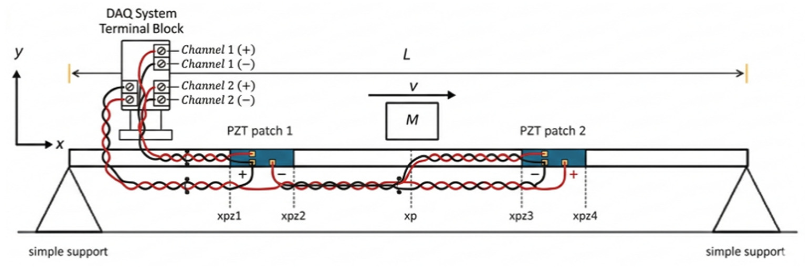
Consider a Euler–Bernoulli beam of length
, subjected to a point mass
traveling along its span (
Figure 1). It is assumed that the mass remains in continuous contact with the beam, such that its transverse displacement at any instant follows the deflection of the beam at its instantaneous position
. Unlike classical formulations assuming constant velocity, the present work considers a generalized motion of the mass, allowing for acceleration effects.
As a result, the inertial interaction between the moving mass and the beam becomes time-dependent and must be explicitly incorporated into the governing equations. The beam dynamics are described in terms of its transverse displacement
, and the governing equation is derived by accounting for the bending stiffness, damping, inertia, and the moving-mass-induced excitation. In addition, geometric nonlinearity associated with mid-plane stretching is included in order to capture amplitude-dependent behavior. The equation of motion of the beam is described as follows:
where
is the beam’s mass per unit length, and
is its bending stiffness. The damping is split into two parts:
is the equivalent strain rate damping coefficient, and
is the viscous air-damping coefficient.
is the Dirac delta distribution. The geometric nonlinearity appears from the axial force
. In classical moving-mass beam problems, the mass is usually assumed to travel along the beam with a constant velocity. Under this assumption, the vertical acceleration of the moving mass results from the beam vibration and the interaction between the beam deformation and the motion of the mass. The instantaneous vertical position of the moving mass is, therefore, Equation (2)
where
represents the position of the mass along the beam axis.
Applying the chain rule, the first-time derivative of
is given as Equation (3)
and the second derivative becomes Equation (4)
where the subscripts denote partial derivatives with respect to space and time.
In the classical formulation where the moving mass travels with constant velocity
, the acceleration term
vanishes and the vertical acceleration reduces to Equation (5)
However, when the motion of the mass includes acceleration
, an additional term appears, leading to Equation (6)
The force applied to the beam by a point mass moving at a given speed with constant acceleration is concentrated at the mass position
and can be written as Equation (7)
where
is the initial position,
is the initial velocity, and
is the constant acceleration of the mass.
In addition to the effects of moving-mass effects, a geometric nonlinearity is introduced by the stretching of the median plane stretching of the beam (Equation (8)). For moderately large transverse deflections, the axial strain is described by the von Kármán relation, which leads to the development of an internal axial force. For a beam with axially immovable ends, this force is given by [
44,
45]
Both beam ends are assumed axially immovable, consistent with the clamped–clamped experimental setup and adopted as a modeling assumption for the simply supported case.
To solve Equation (1) with appropriate initial and boundary conditions, the following modal form is used.
where
stands for the
mode-shape function of the beam and
its corresponding modal amplitude. For uniform beams with simply supported or fixed–fixed boundary conditions, the mass-normalized mode shape
, mode shape
and the amplitude factor
are given in
Table 1.
are the eigenvalues from the transcendental equation .
The natural mode shapes
satisfy the orthogonality conditions (Equation (10)):
where
denotes the Kronecker delta, and
is the undamped natural frequency of the
mode of the beam, as in Equation (11):
Substituting the modal expansion of Equation (9) and the
from Equation (7) into Equation (1), the following equation results:
Multiplying both sides of Equation (12) by
,
, integrated throughout
, and applying the modal orthogonality conditions, one obtains Equation (13)
After rearrangement, the modal governing equation and its associated coefficients are expressed by Equations (14) and (15), respectively.
Substituting Equation (9) into Equation (8) yields the nonlinear term given in Equation (20).
The geometric coupling coefficients are defined as
So that, using Equation (21)
Now, the nonlinear contribution in the governing Equation (14) is
Using the modal expansion
Projecting this term from Equation (24) onto mode
gives
Then, the projected nonlinear term Equation (25) becomes
Substituting the expression of
from Equation (22), the nonlinear
-mode contribution is
Therefore, the nonlinear term appearing in the
-th modal equation is
Substituting Equations (21) and (26) into Equation (29) yields the nonlinear stiffness term.
where
is the modal mechanical damping ratio and
is the natural frequency of the beam. Thus, the damping ratio
involve both viscous air and strain-rate damping effects and can be given as Equation (31)
where
and
.
3. Electromechanical Coupling and Multi-Patch Formulation
This section presents the electrical model associated with the piezoelectric energy harvesting system. The piezoelectric energy harvesting system, illustrated in
Figure 1, is equipped with a piezoceramic patch bounded by the zone
in order to harvest power from the vibrations caused by the moving mass. The aim is to determine the relationship between the surface strain of the beam and the voltage output of the piezoceramic. Equation (1) governs the beam’s behavior, and it is assumed that the piezoelectric energy generation and patch have a negligible impact on the beam vibration. This assumption of negligible mechanical back-coupling from the piezoelectric layer to the host beam follows the modeling approach adopted in [
38]. To derive the governing electromechanical equations, the beam was considered with a single piezoelectric layer connected to the external resistance
. Under one-dimensional strain variations, the electric displacement (Equation (32)) component along the
direction is
and are, respectively, the piezoelectric constant and permittivity constant.
The average shear strain of the piezoelectric layer can be approximated as Equation (29)
Here,
refers to the transverse displacement of the beam, and the distance from the mid-plane is denoted as
. The charge accumulated on the electrode surface is defined by Equation (34)
Assuming the electric field is uniform across the piezoelectric layer, and letting
denote the voltage between its top and bottom faces, the through-thickness field
can be approximated as
Using Equations (34)–(36), one obtains Equation (37), which characterizes the voltage generated across the load resistance by the piezoelectric patch.
where
,
,
,
, and
are the piezoelectric capacitance, the width of the patch, its thickness (Equation (38)), the distance from the mid-plane, and the beam’s thickness, respectively.
Let us consider
piezoelectric patches. When the piezoelectric patches are connected in parallel across a resistive load
, the equivalent electrical capacitance
of the harvesting system is equal to the sum of the individual patch capacitances defined by Equation (39)
The capacitance of the
-th piezoelectric patch is given by Equation (40)
Following the standard electromechanical coupling formulation, the voltage (Equation (41)) associated with the electrical circuit can be written as
For the
-th piezoelectric patch, the coupling coefficient associated with the
-th vibration mode is defined by Equation (42)
where
and
denote the start and end positions of the
-th patch. The equivalent coupling coefficient
(Equation (43)) associated with multiple patches connected in parallel is therefore expressed as
To evaluate the PZT patch voltage, Equations (14) and (41) should be solved. The methodology for solving these equations will be developed in the following section.
4. Numerical Solution
It should be noted that, due to the moving mass, the one-mode analysis may lead to inaccurate results. Multimode formulation and computation with a large number of modes is thus required. The resulting nonlinear state-space system is integrated numerically in MATLAB 2024b using the solver ode45, which is based on an explicit Runge–Kutta scheme with adaptive step-size control. At each integration step, the instantaneous position of the moving mass is updated according to its prescribed motion law, and the corresponding time-dependent coefficients are evaluated. Once the modal coordinates are obtained, the beam displacement field is reconstructed from the modal expansion. The governing nonlinear electromechanical system is solved numerically in the time domain.
Based on the multimode approach, the following nonlinear differential system results.
The off-diagonal terms () in , and are retained and account for the inter-modal coupling induced by the moving mass given by Equations (45)–(48).
The nonlinear stiffness contribution is given by Equation (49)
For more clarity, the formulation can be illustrated for a single mode. The state variables are defined by Equation (50):
In this case, Equations (14) and (45) can be represented as a first-order differential system:
The cubic term
accounts for the von Kármán geometric nonlinearity, whose coefficient takes the explicit form given in Equation (52).
The voltage response is simultaneously obtained from the electromechanical coupling equations. The instantaneous harvested power delivered to the resistive load is given by Equation (53)
The average harvested power is evaluated over the duration of the moving mass passage.
It should be noted that the semi-analytical results are highly dependent on the number of modes used. A convergence analysis was therefore performed, where the modal basis was progressively enlarged until the variations in the predicted displacement, voltage, and harvested power fell below 1% between successive refinements. On this basis, 20 modes were retained for the simply-supported (S-S) case and 10 for the clamped–clamped (C-C) case in all semi-analytical computations.
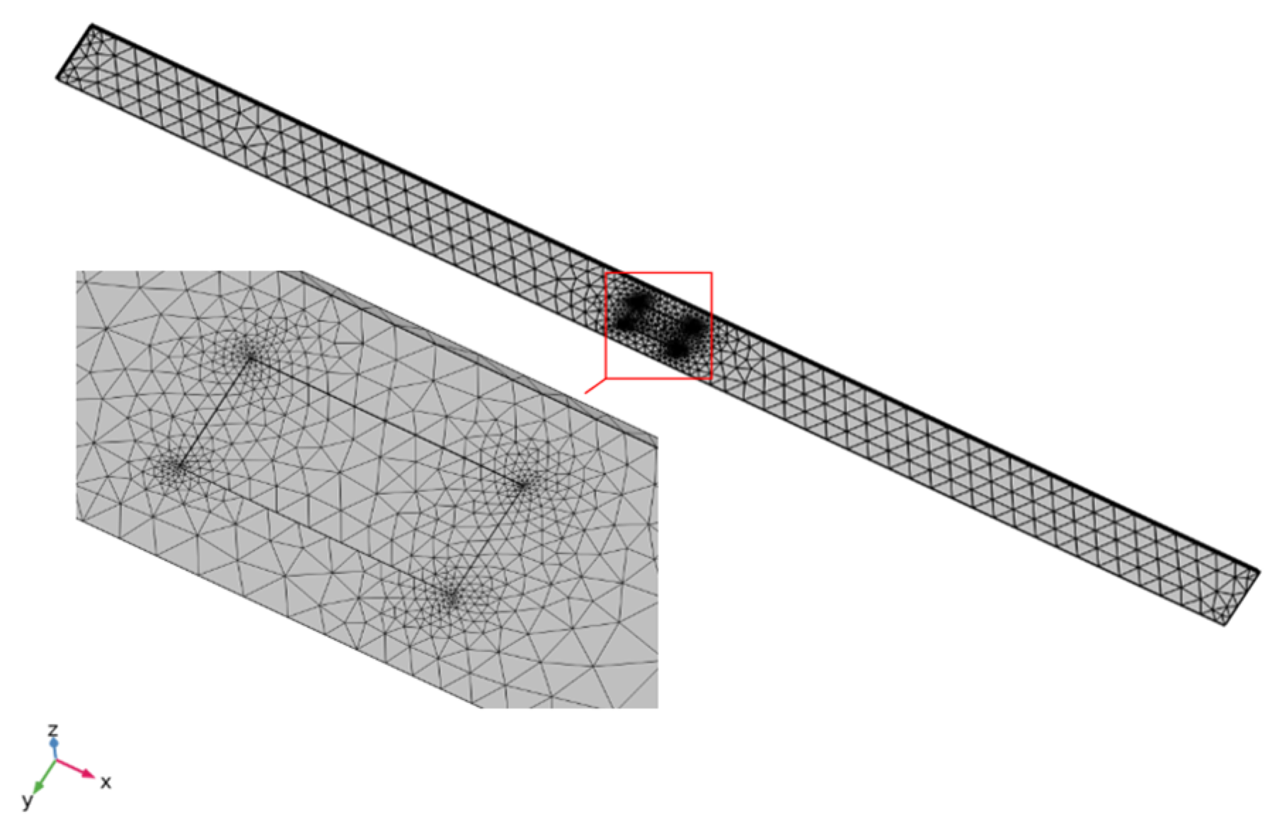
The coupled electromechanical response of the harvester is computed using the finite element software COMSOL 6.2 Multiphysics, in which the piezoceramic patch, the beam and the moving load are discretized together. The model couples the Solid Mechanics and Electrostatics interfaces through the built-in Piezoelectricity Multiphysics coupling, which enforces the linear piezoelectric constitutive relations in stress–charge form. Perfect bonding is assumed at the beam–patch interface, so displacement continuity is imposed across the bonded surface, and the adhesive layer is neglected.
The domain is discretized with 8482 tetrahedral elements. As shown in
Figure 2, a non-uniform mesh is adopted: most of the beam is meshed coarsely to keep the computation time reasonable, while the region around the piezoceramic patch is refined to resolve the steep strain gradients near the patch edges. This combination of a global coarse mesh and a local fine mesh provides a good compromise between accuracy and computational cost. A mesh-convergence study was carried out by progressively refining the discretization and monitoring the peak output voltage until further refinement produced a negligible change.
The moving load does not require a dedicated mesh; it is implemented as a vertical force travelling along the top surface of the beam at a prescribed velocity. For the electrical boundary conditions, the lower electrode of the patch is grounded
, while the upper electrode is defined as a single equipotential terminal connected to an external resistive load R
1 through the electrical circuit interface. Charge conservation is enforced within the patch, and the remaining external surfaces are electrically insulated (zero charge). The BDF scheme was used with a maximum order of 5, a relative tolerance of 0.001 and a scaled absolute tolerance of 0.001, and the resulting systems were solved with the direct MUMPS solver. using a fixed time step of
over the 8482-element mesh. The time step sets the spatial resolution of the load path at the prescribed velocity that the load moves per step, which is small relative to the local element size near the piezoceramic patch, so the load traverses the mesh smoothly without skipping elements. To verify this choice, the simulation was repeated with time steps of 50, 10, 1 and 0.5 ms, and the resulting peak-to-peak output voltage is reported in
Table 2.
The 50 ms step is strongly under-resolved, underestimating the peak-to-peak voltage by about 25% and suppressing the oscillatory content of the response. Reducing the step to 10 ms recovers most of the signal but leaves an error of about 6%, concentrated at the trough. At 1 ms, the response is fully resolved: halving the step to 0.5 ms changes the peak-to-peak voltage by less than 1%. A time step of was therefore adopted for all time-domain analyses, providing a converged response at minimal computational cost.
5. Results and Discussion
The parametric trends presented in this section, namely, the patch length, load resistance, boundary conditions, mass acceleration, and geometric nonlinearity, are established through the semi-analytical model and cross-validated against COMSOL finite element simulations. The effects of the patch number and moving-mass magnitude, presented in
Section 5.3, are further confirmed experimentally in
Section 6.
The dynamic deflection of a simply supported (S-S) and clamped (C-C) beam excited by a moving mass as well as its piezoelectric coupling to a bonded patch are analyzed. When the beam bends, the patch strains and generates a voltage. The two inputs that matter most are the mass of the traveler and its speed, which set the strength and timing of the excitation and therefore the energy output. Using the geometric and material data in
Table 3, the coupled ordinary differential Equations (40) and (44) are solved.
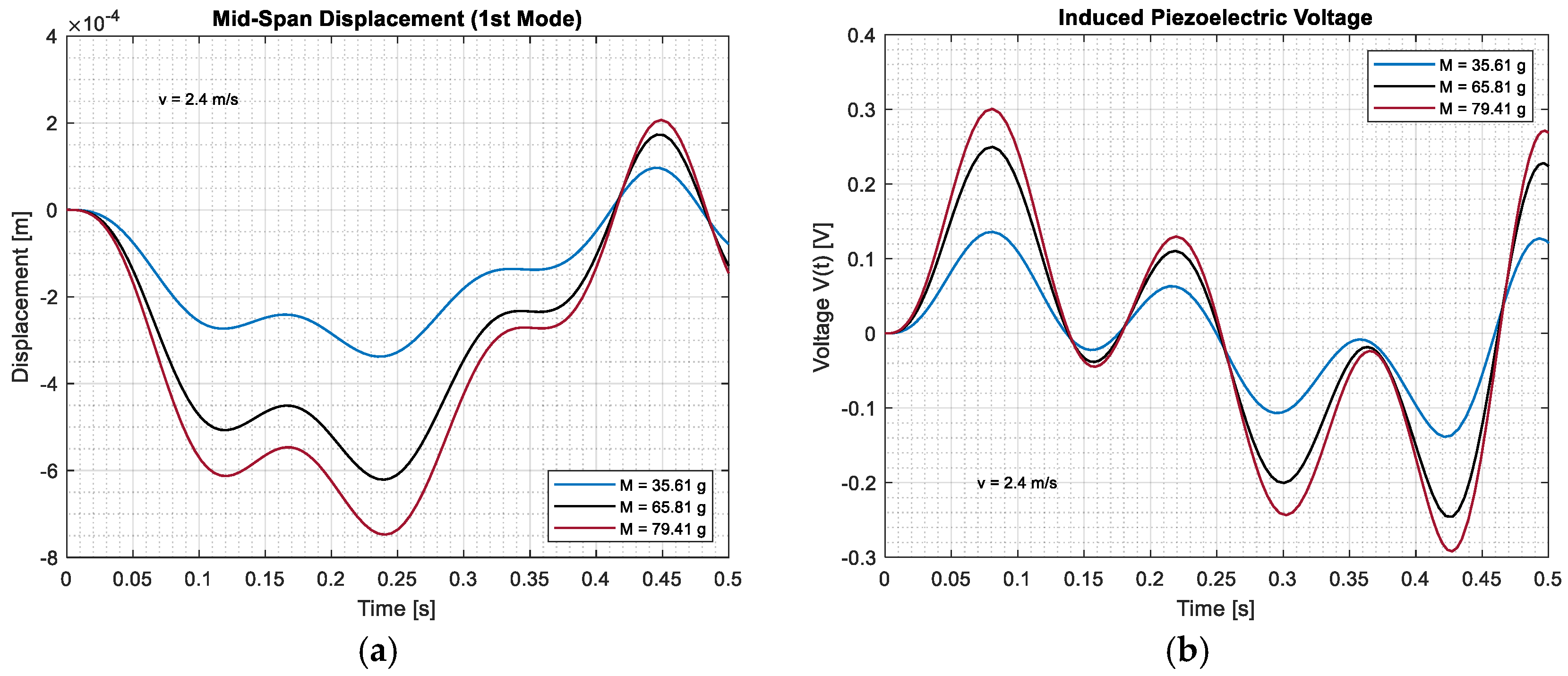
Based on one-mode analysis, the temporal response of the fundamental-mode mid-span displacement and the corresponding induced voltage produced by the vibration of the simply supported (S-S) beam are presented in (
Figure 3a,b). These figures analyzed the sensibility of the electromechanical system to the moving mass, where several mass values are examined to determine their effect on the displacement and induced voltage.
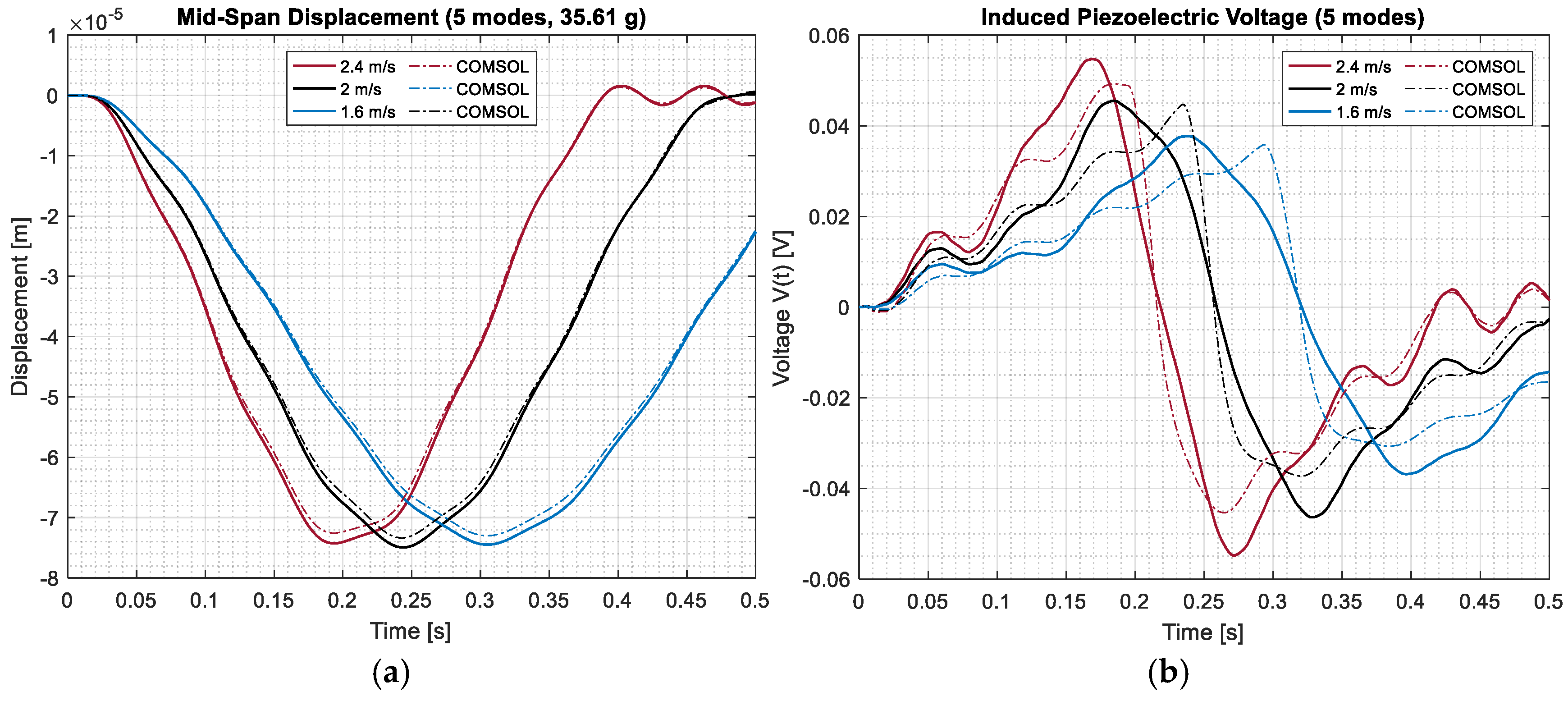
Figure 3 presents the theoretical mid-span response for moving masses of
,
, and
traveling at a fixed speed of
. Increasing the mass increases the structural displacement and the depth of the troughs. The transient response after mass departure is increased in amplitude, but the phase of the oscillation is not changed, as the peaks and troughs occur at the same time. The induced piezoelectric voltage follows the same trend, with heavier masses resulting in larger positive and negative peaks. In practice, the heavier the traversing masses are, the greater the electrical output but the greater the mechanical strains are, which should be verified against design limits.
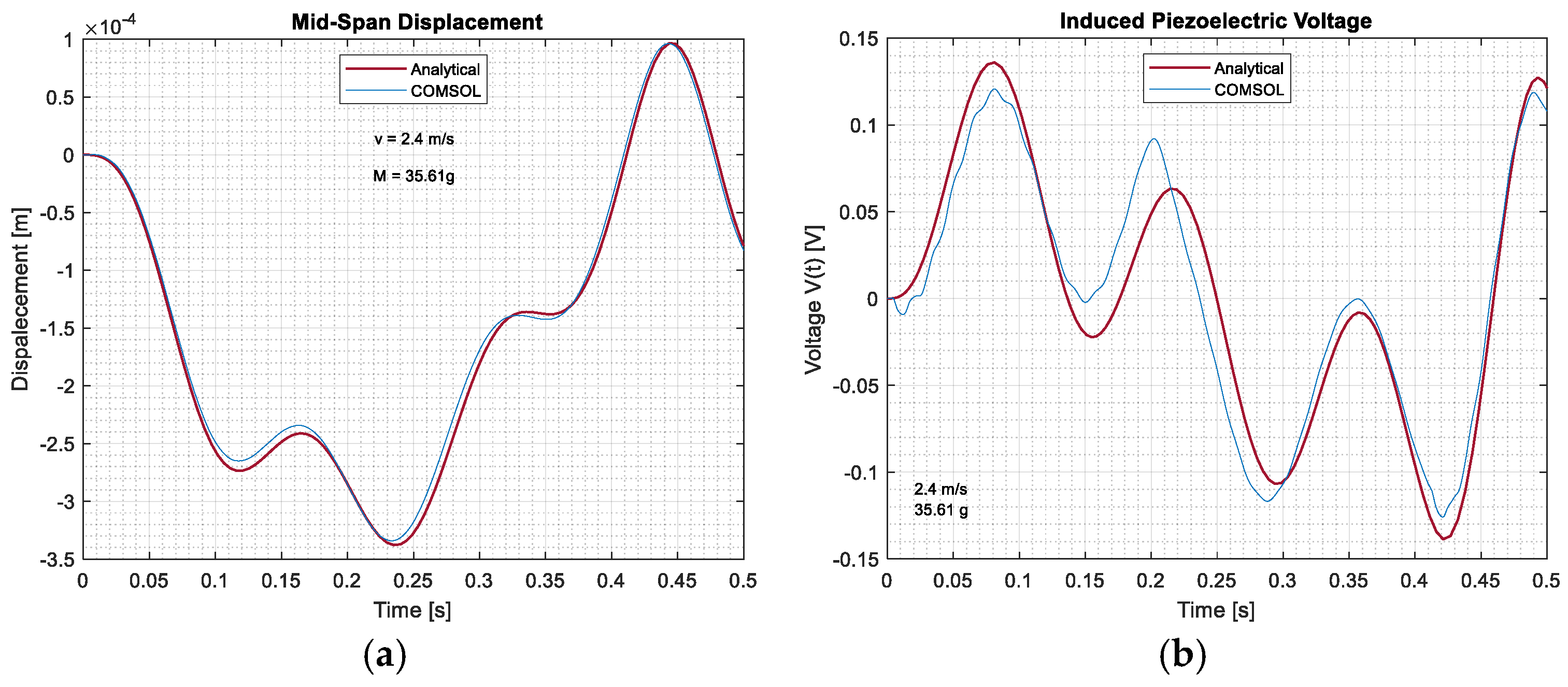
A comparison of the semi-analytical and COMSOL-based simulations for both the mid-span displacement and piezoelectric patch voltage with respect to the travelling mass along the simply supported beam is depicted in
Figure 4. In the displacement plot (
Figure 4a), the two curves overlap nearly completely, which indicates that the governing dynamics of the beam vibration behavior is captured by the reduced model. The voltage plot (
Figure 4b) has the same general timing, but the mismatch is easily noticed there. This is because the response in voltage depends strongly on how the strain is distributed, and a single vibration mode cannot account for all those small variations. By adoption of this single-mode simplification, we naturally omit certain electromechanical details, which explains the slight difference in amplitude observed in COMSOL. Despite this, the simplified model remains satisfactory, even though adding more modes would undoubtedly improve its agreement with the results.
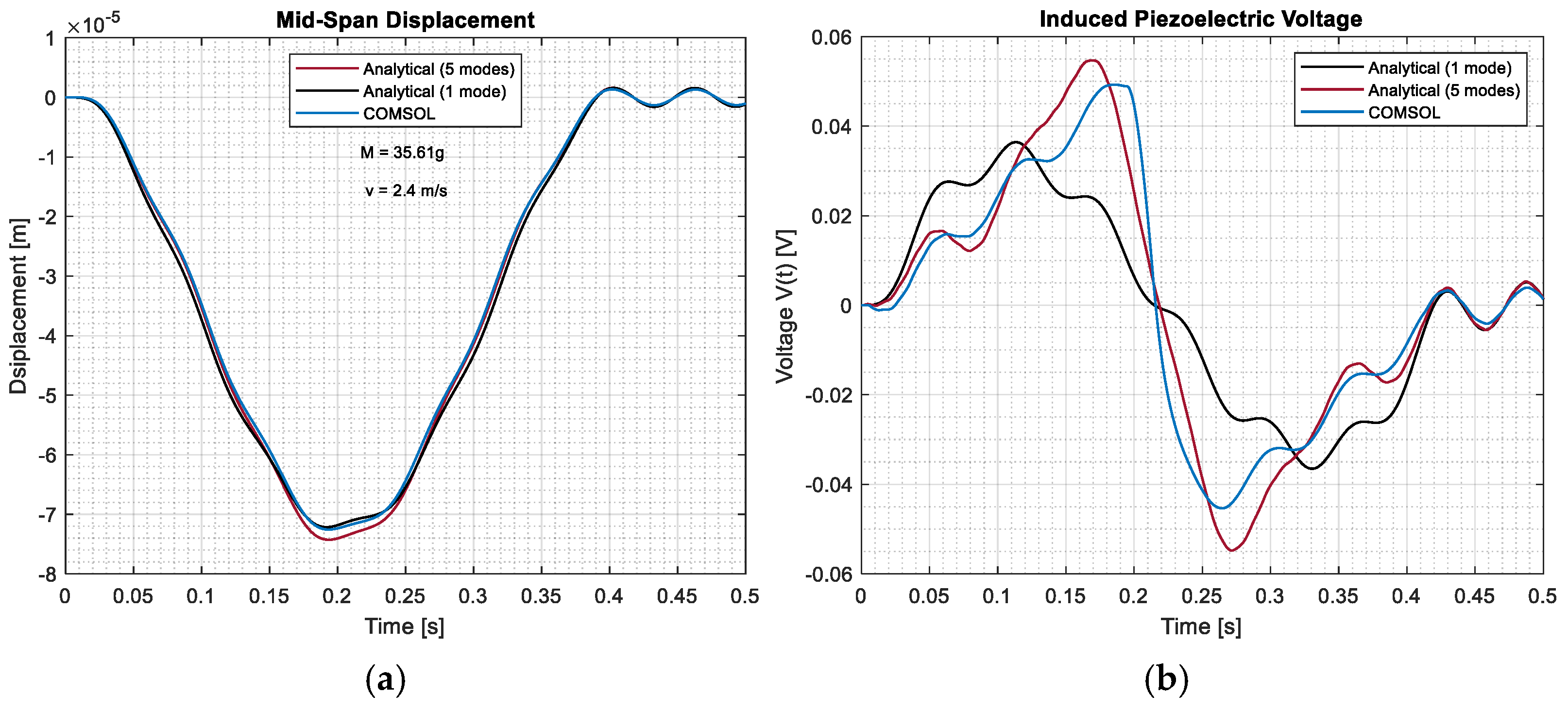
Figure 5 and
Figure 6 show the mid-span displacement and induced voltage of a clamped–clamped beam under a moving mass, comparing COMSOL with semi-analytical models using one and five modes. For the displacement response, the amplitudes are much lower than for a simply supported beam because the fixed ends make the beam more rigid. The five-mode model nearly coincides with the COMSOL results. The voltage graph follows the same pace as the five-mode solution, which matches COMSOL well in phase and amplitude, while the single-mode solution captures the primary rise but drops after
. It can be observed that the clamped–clamped response depends on the number of modes deployed, particularly for voltage, which depends on the curvature, and that adding just a few modes is enough to reach good agreement with the numerical results.
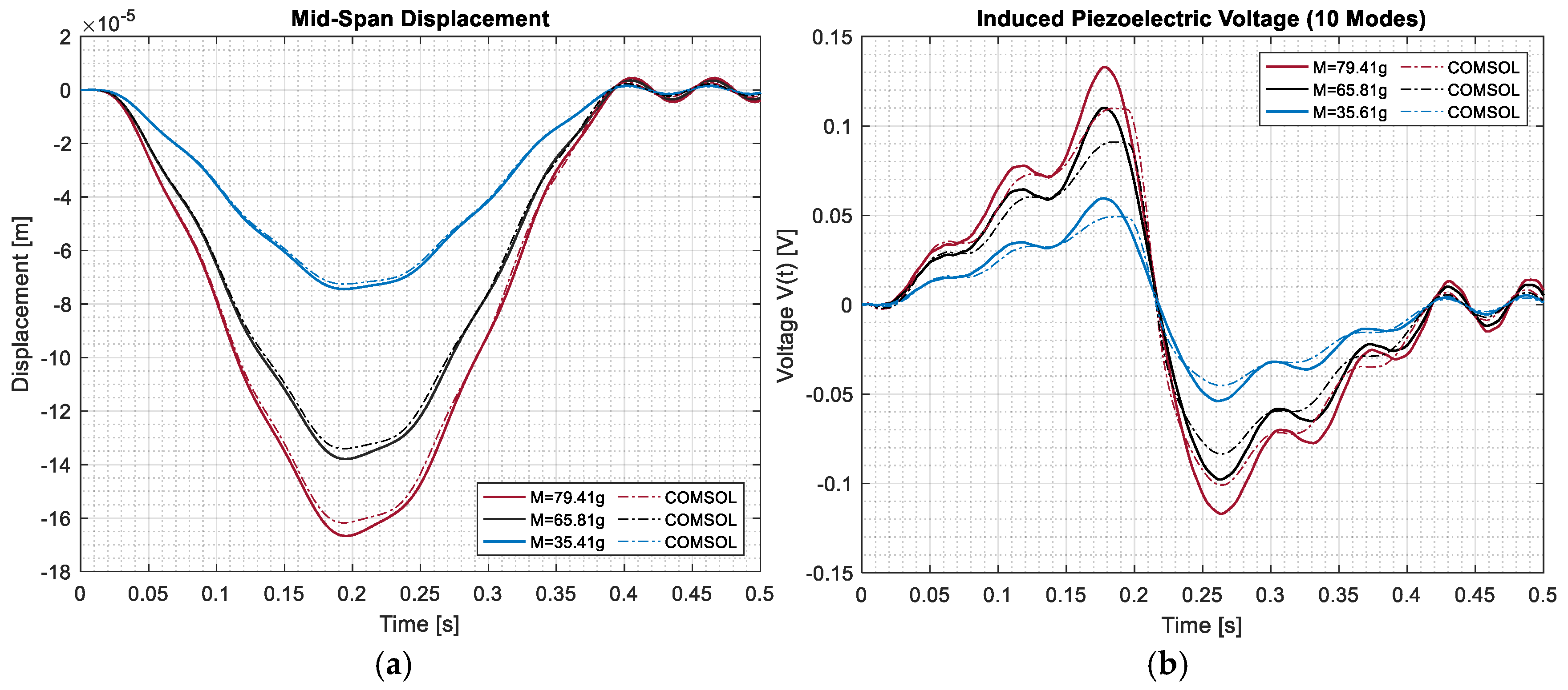
As shown in
Figure 7, increasing the moving-mass value leads to a stronger dynamic excitation of the clamped–clamped beam. This causes a larger mid-span displacement amplitude, with the maximum deflection increasing progressively as the mass rises from
to
. The same trend is observed in the induced voltage response, where heavier moving masses generate higher voltage peaks as a result of the increased strain developed in the beam. While the overall shape and timing of the responses remain similar for all mass values, the amplitudes are clearly amplified as the moving mass increases. The semi-analytical predictions remain in close agreement with the COMSOL results for both the displacement and voltage responses.
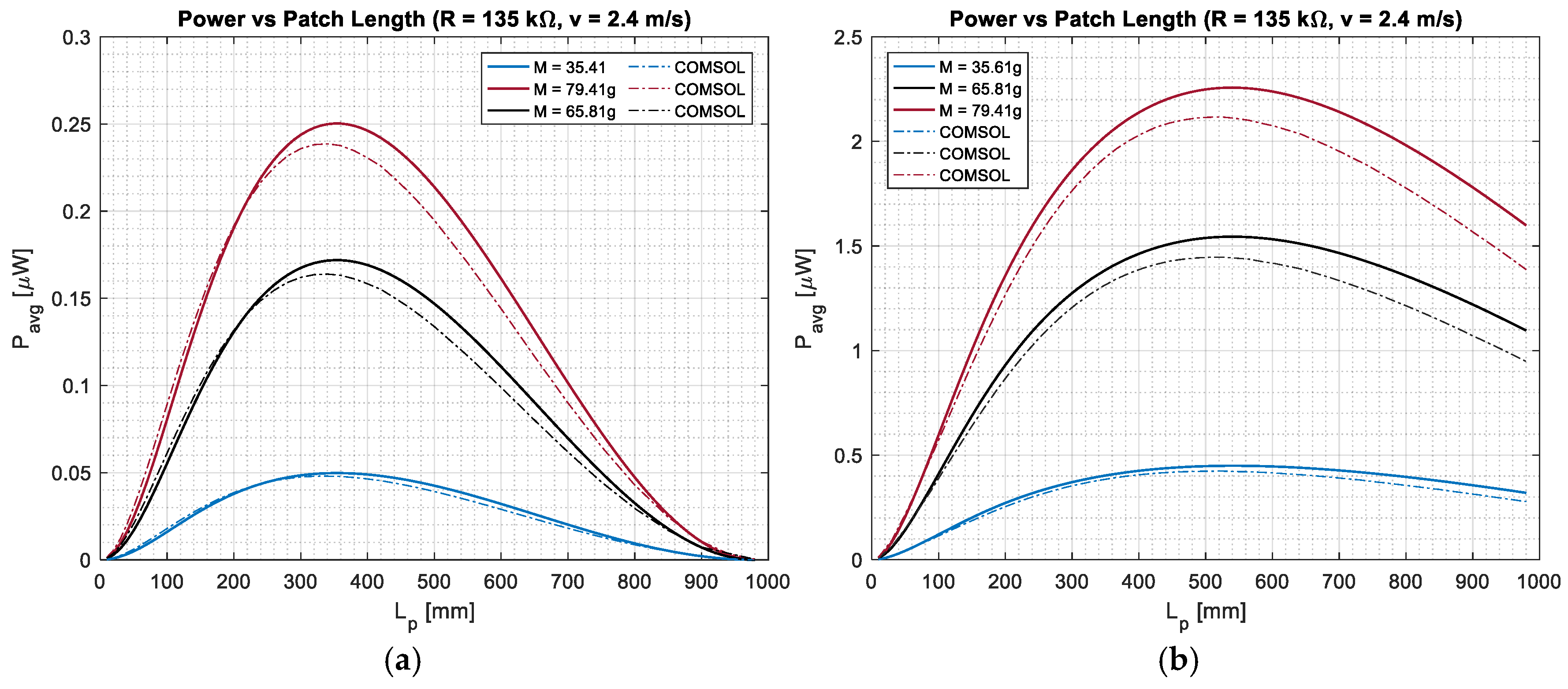
Figure 8 presents the variation in the average harvested power with respect to the piezoelectric patch length
for both simply supported and clamped–clamped beam configurations with various moving-mass values
. The results are calculated with external resistance
and
. In both configurations (C−C and S−S beam), the harvested power increases with the patch length, reaches a clear optimum, and then decreases as the patch extends toward the beam ends. Increasing the moving mass raises the overall power output in all cases. At the same time, the simply supported beam produces considerably higher power levels than the clamped–clamped beam, confirming its more favorable strain distribution for energy harvesting. In addition, the optimal patch length clearly depends on the boundary conditions: it occurs at larger fractions of the span (
) for the simply supported beam, while it is shifted toward shorter lengths (
) in the clamped–clamped case. This shift reflects the more localized curvature in the clamped–clamped beam, which limits the effective region contributing to energy conversion.
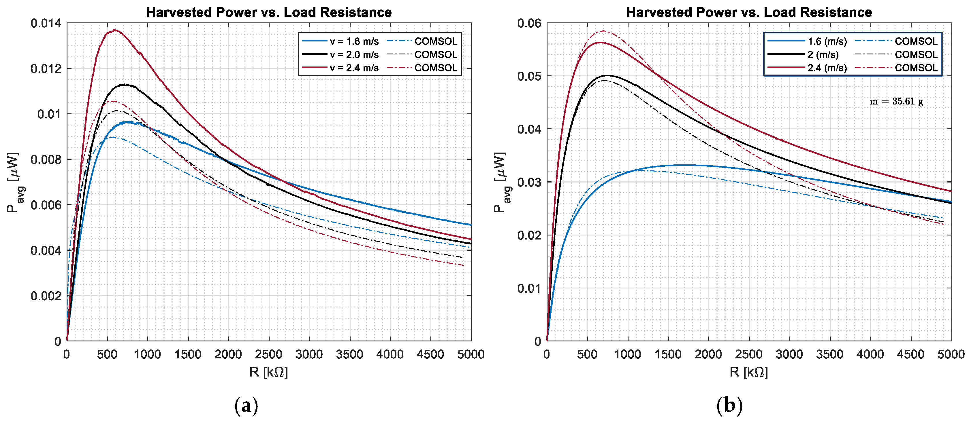
Figure 9 compares the average harvested power as a function of the load resistance
for both simply supported and clamped–clamped beam configurations, at a fixed moving mass of
and for three speeds
. In both configurations, the harvested power follows the classical trend: it is low near short-circuit conditions, increases to a maximum at an optimal resistance, and then decreases as the resistance approaches open-circuit conditions. However, the simply supported beam consistently delivers higher power levels than the clamped–clamped beam across all speeds, due to its larger deformation and strain distribution. The peak power increases with speed in both cases but remains significantly higher for the simply supported configuration. Additionally, the optimal load resistance differs between the two cases, being located at higher values (
) for the simply supported beam and at lower values for the clamped–clamped beam, reflecting differences in the effective electromechanical coupling and system impedance.
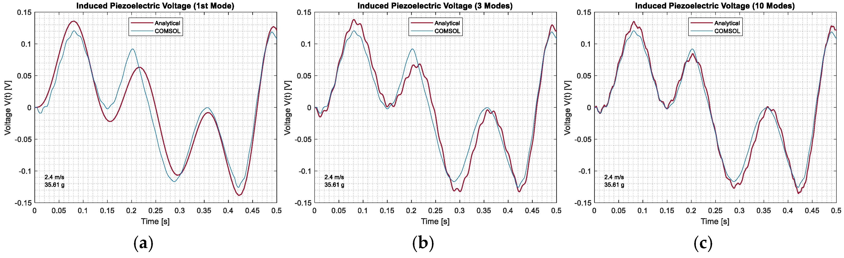
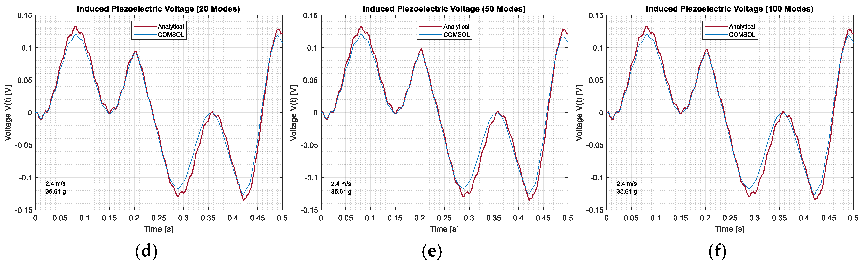
Figure 10 illustrates the convergence of the semi-analytical voltage response with respect to the number of retained modes. With a single mode, the semi-analytical response captures the general phase and sign of the voltage signal, but differences remain in the amplitude, together with a slight phase shift in the regions with sharp variations. As the number of modes is increased from 3 up to 10, the semi-analytical results move progressively closer to the COMSOL results, and both the amplitude and the phase agreement improve noticeably. With 20 modes, the two curves are practically indistinguishable. The induced voltage is directly related to the strain and curvature, and it is therefore more sensitive than the displacement to the higher-mode contributions. A sufficient number of modes must be retained if the electromechanical response is to be captured accurately.
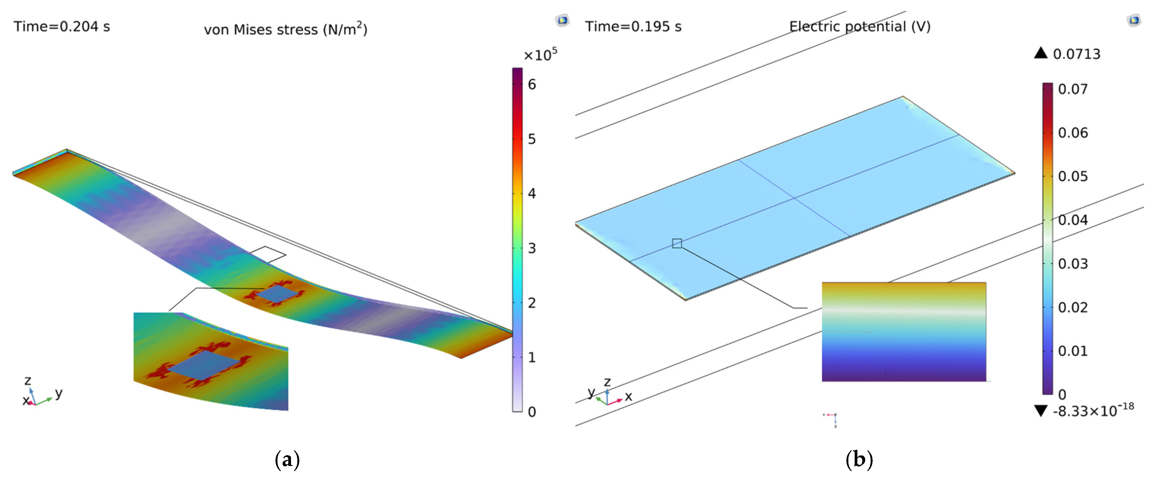
Figure 11 presents the instantaneous mechanical and electrical response of the clamped–clamped piezoelectric beam under a moving mass of
travelling at
. The von Mises stress field shows a symmetric bending shape. This shape is expected when both ends of the beam are clamped. The stress is highest at the two fixed ends and right under the mass. The electric potential on the piezoelectric layer is almost the same everywhere on the patch. This makes sense because the mass is near the middle of the beam at this moment. The strain on the piezoelectric is almost symmetric, so the potential is almost the same too.
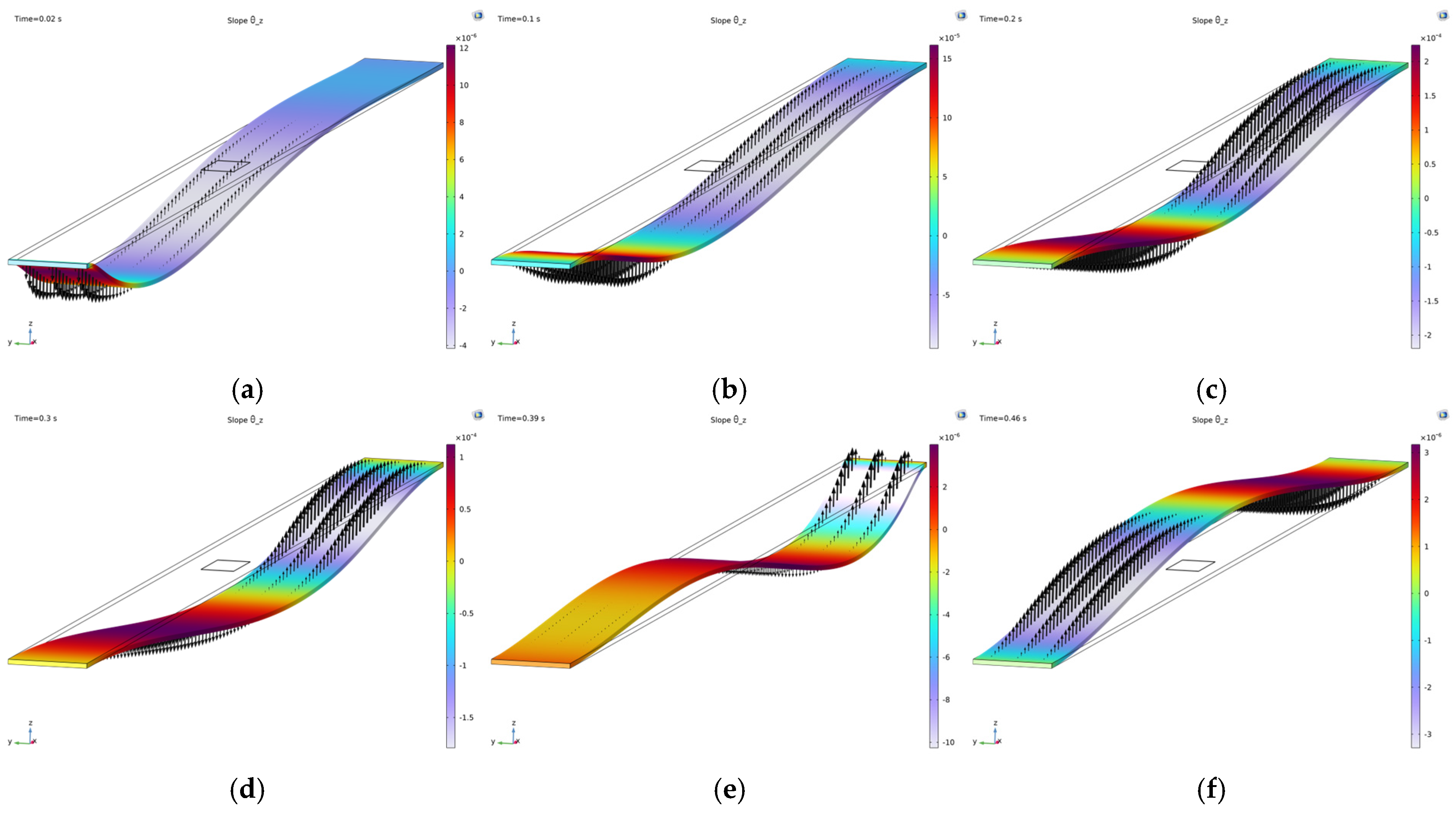
Figure 12 shows the slope field of the beam at six different positions of the moving mass along the span. The arrows indicate the local rotation of the beam cross-section, and the location of the maximum deflection also shifts during the whole motion of the mass, illustrating the time varying nature of the loading. This observation guides the positioning of the piezoelectric patch: since the electrical output of a piezoelectric transducer is directly related to the mechanical strain it experiences, the active material must be bonded to the area where the slope varies the most.
5.1. Acceleration Effect
This subsection reveals the impact of the moving-mass acceleration on the energy harvesting efficiency. In contrast to the constant speed assumption, commonly adopted in classical moving-mass problems, in real cases, it can speed up, slow down, or brake. So, acceleration modifies the instantaneous crossing velocity, and it adds an extra inertial term to the contact between the mass and the beam. This changes the impact on both the structural vibrations of the beam and the electrical energy output. To assess this behavior, several acceleration levels are considered while all other parameters remain constant.
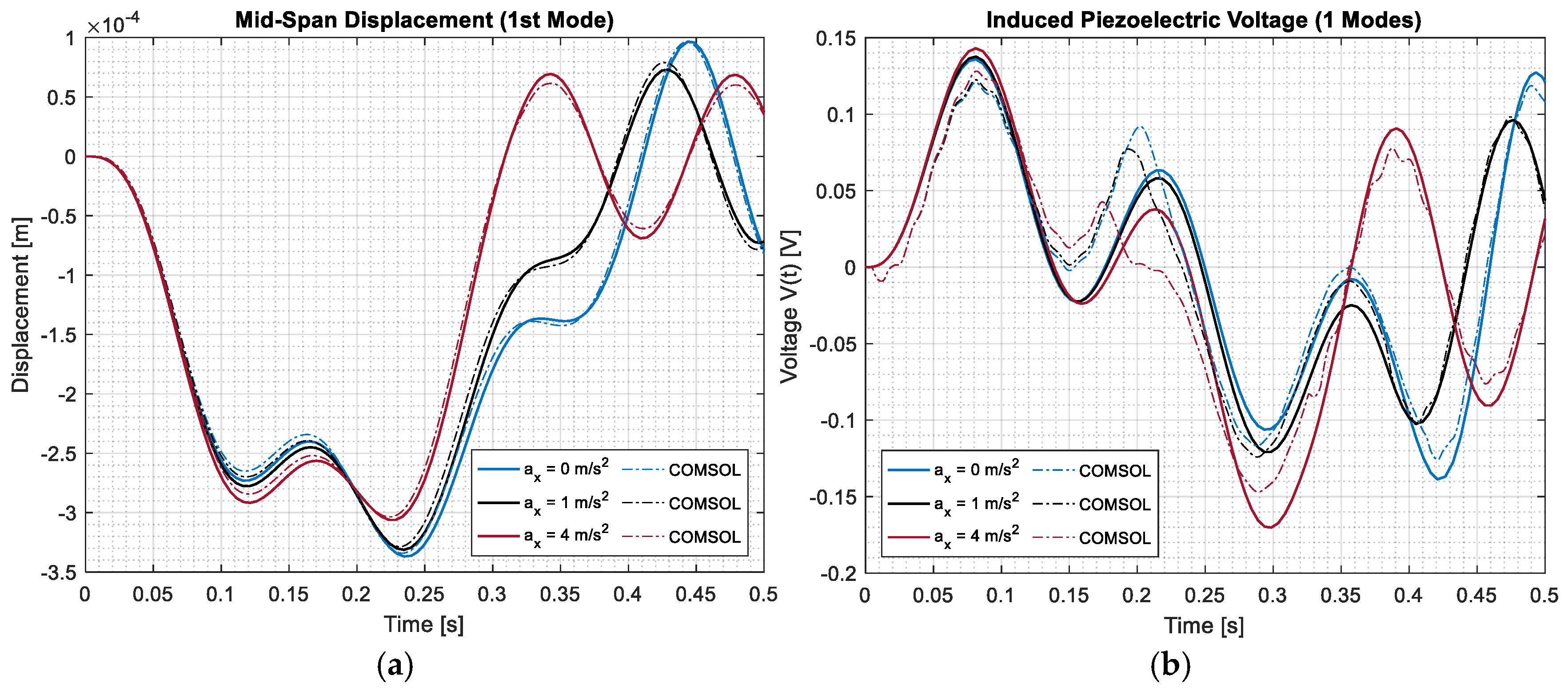
As shown in
Figure 13, including the acceleration of the moving mass leads to a stronger inertial excitation of the beam. This results in slightly higher displacement and voltage amplitudes, along with small phase shifts in the response. The displacement response of the beam is well captured using only the first mode, and it is in good agreement with that of the COMSOL simulation. However, the voltage shows more noticeable differences, especially in amplitude and near the sharp variations. This is because the voltage depends on the strain and the curvature, which are more sensitive to higher modes that are not included here. Even so, the semi-analytical model still captures the overall trend and timing of the response while highlighting the limitations of using only one mode.
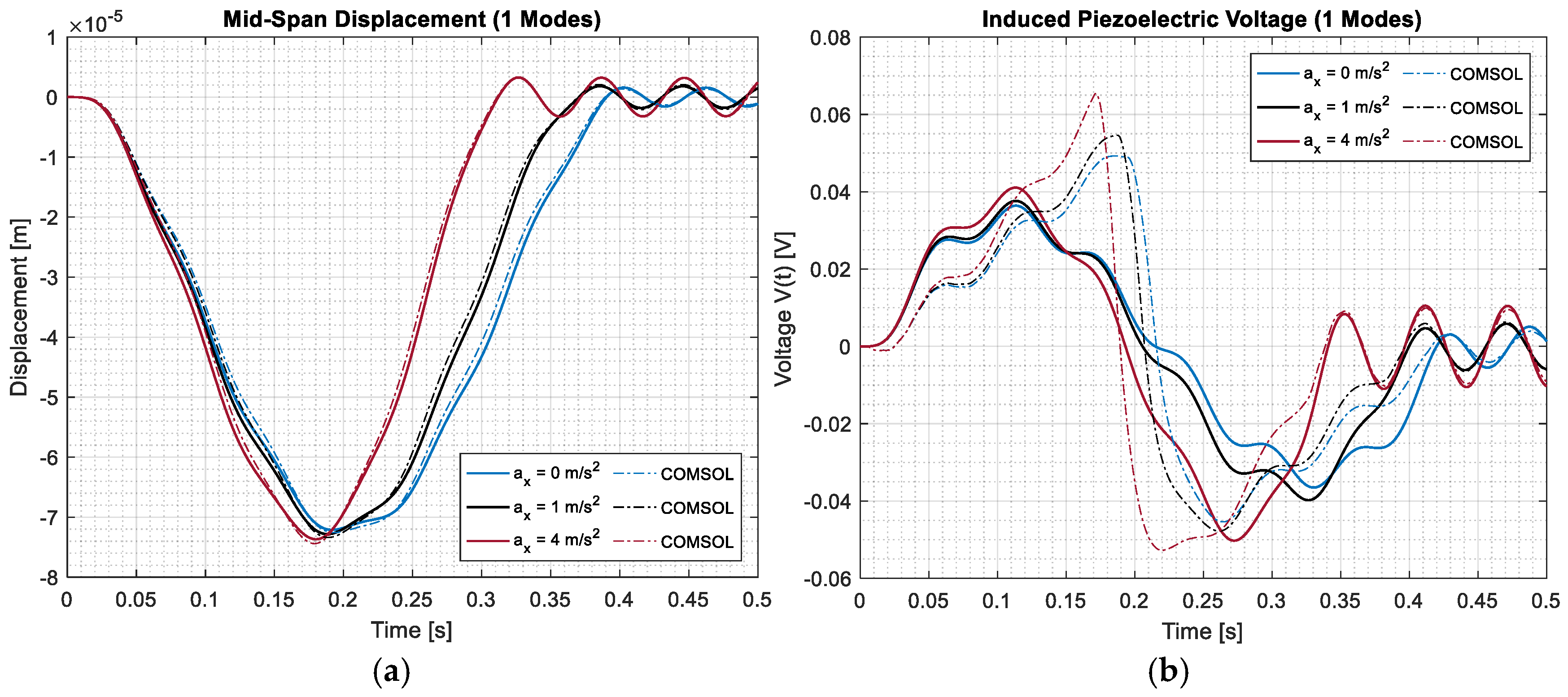
From
Figure 14, the effect of acceleration on the displacement and piezoelectric voltage responses of the C−C beam is observed. As depicted in this figure, increasing the acceleration of the moving mass leads to larger displacement amplitudes and noticeable phase shifts in the response. The voltage signal undergoes the same effect, where higher acceleration generates more sharp peaks. The displacement is still well captured by the first mode, and the semi-analytical model matches COMSOL well. As in the simply supported case, the gap is important, mostly around the sharp parts of the signal. This is mainly because the voltage depends on the strain and curvature, and these need higher modes that are not included in the single-mode model. The semi-analytical model captures the main effect of acceleration on both the mechanical and electrical responses while highlighting the limitations of using only one mode. The next section will explore the role of higher modes and their impact on the energy harvesting performance.
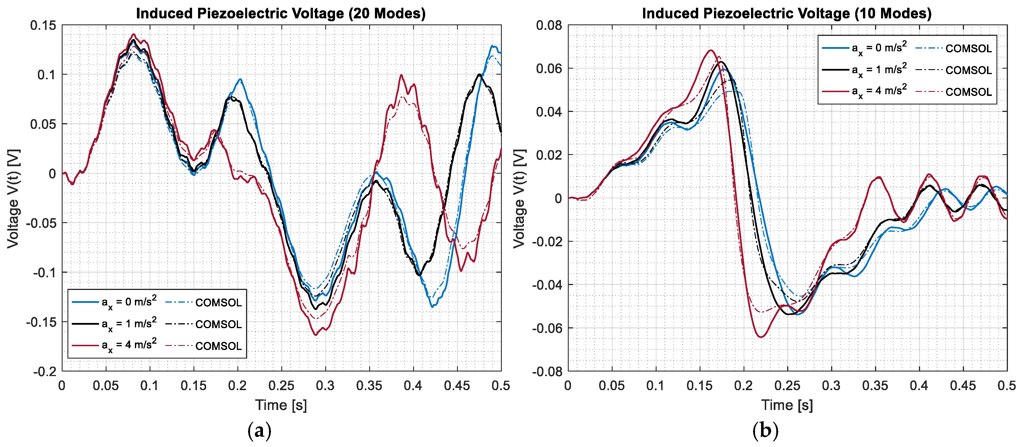
As shown in
Figure 15, when a sufficient number of modes is included (10 and 20 modes), the semi-analytical voltage response closely follows the COMSOL results for both configurations. Increasing the acceleration leads to higher voltage amplitudes and noticeable phase shifts, with the effect becoming more pronounced as the acceleration increases. Compared to the single-mode case, the inclusion of higher modes significantly improves the agreement, especially around regions with sharp variations where the voltage is more sensitive to local curvature effects. The good agreement between the semi-analytical model and the COMSOL simulation results confirms that accurately capturing the voltage response under moving-mass acceleration requires accounting for higher-mode contributions. It also shows that the accelerated mass significantly modifies the strain field in both configurations.
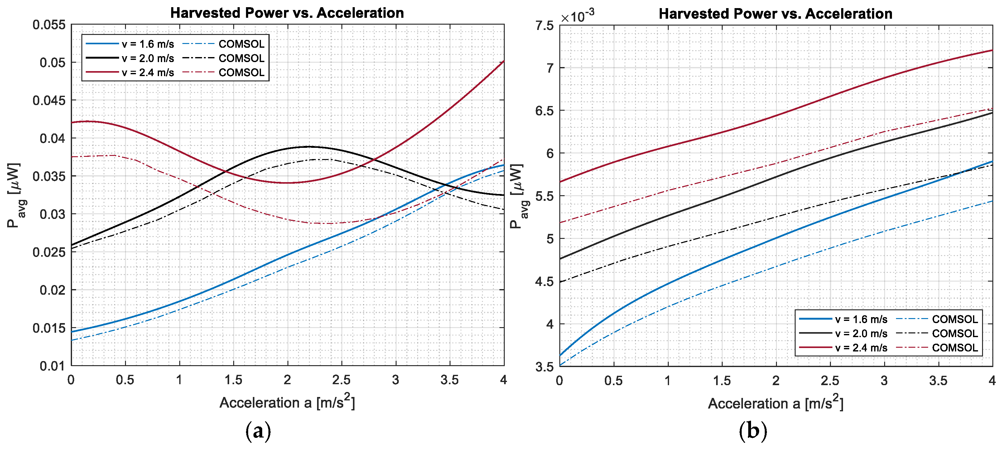
The average harvested power was also computed as a function of acceleration for three moving-mass speeds and compared with the COMSOL results (
Figure 16). For the clamped–clamped beam, it increases monotonically with acceleration at all speeds. For the simply supported beam, the trend is non-monotonic and speed-dependent, with the curves for different speeds crossing one another within the explored range.
5.2. Effect of Geometric Nonlinearity
In the previous subsection, geometric nonlinearities were intentionally neglected, allowing the beam response to be described using the classical linear Euler–Bernoulli formulation. The present subsection incorporates the geometric nonlinearity of von Kármán type in order to improve the displacement and voltage predictions. In this study, a simply supported beam (S−S) exposed to a moving mass is considered. The same axially immovable assumption applies here. The semi-analytical study uses 150 modes.
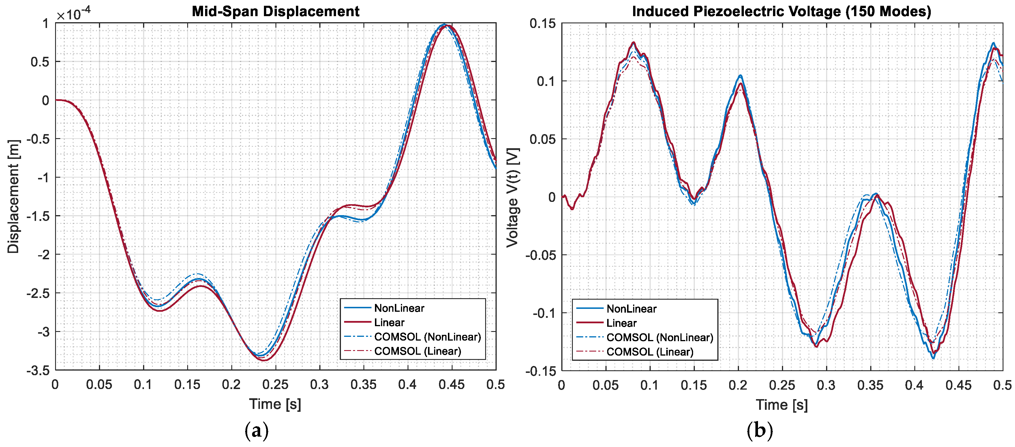
As shown in
Figure 17, the effect of geometric nonlinearity on the displacement remains relatively small, with the nonlinear and linear responses almost overlapping over the entire time range. Only slight differences can be observed around the peaks, indicating that the global motion is not strongly affected under the considered conditions. In contrast, the voltage response shows more noticeable differences between the linear and nonlinear cases, particularly near regions with higher curvature. This is expected since the induced voltage depends directly on the strain and curvature, which are more sensitive to nonlinear effects. Despite these differences, both the semi-analytical predictions remain in good agreement with the COMSOL results, confirming that the proposed model is able to reveal the influence of geometric nonlinearity on the electromechanical response.
Quantitatively, the relative error between the linear and nonlinear responses remains around 1.6% (peak) and 2.6% (RMS) for the mid-span displacement. For the induced voltage, the peak relative error reaches about 3.3%, with an RMS error of 4.6% over the full-time response, and locally, the largest discrepancy of about 6.8% is observed near t ≈ 0.20 s, consistent with the higher sensitivity of the voltage response to curvature-driven nonlinear effects.
5.3. Multi-Patch Effect
The result of using two piezoelectric patches separated by a gap distance is explored in this subsection. In the comparison with a single-patch configuration, the two-patch arrangement allows the active material to be placed over different regions of the beam. Since the bending strain is not uniform along the span, the gap distance has an important role in quantifying the amount of strain energy captured by each patch. The equivalent capacitance and the general electromechanical coupling are also changed by the connection type between the two patches. Several values of are therefore considered while all remaining parameters are kept unchanged.
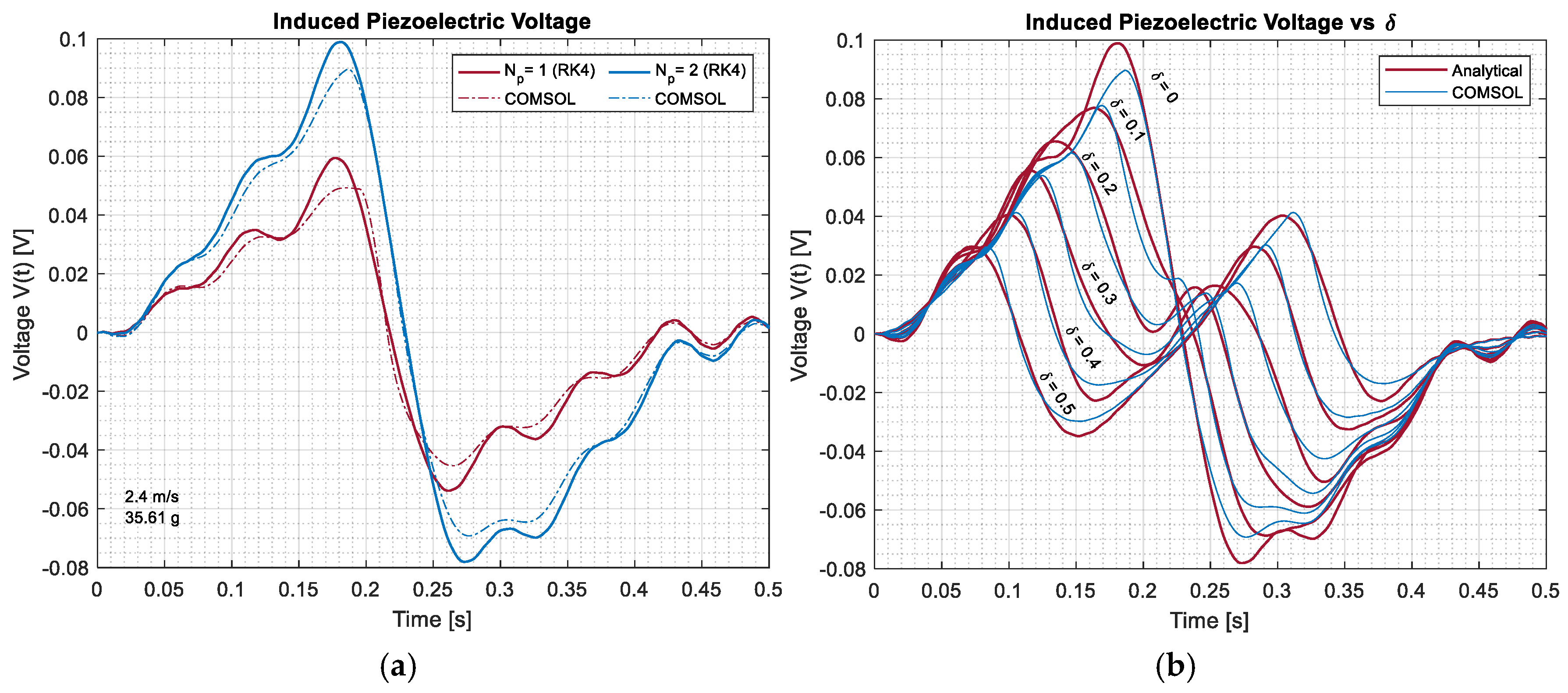
In
Figure 18, an example of the induced piezoelectric voltage in a beam subjected to a moving-mass excitation is given, where different configurations and spatial distributions are provided. In the first plot, we can see the voltage response for a single-patch and a dual-patch case, where the addition of a second patch enhances the harvested voltage and modifies the temporal response due to changes in the electromechanical coupling and modal contribution induced by the moving load. The second plot examines the influence of the inter-patch distance
, showing that varying
significantly affects both the amplitude and phase of the voltage signal, reflecting the interaction between the moving-mass position and the spatial sensitivity of the piezoelectric layers.
6. Experimental Setup
The experimental validation is carried out on the same physical system as the one modeled analytically and numerically in
Section 2,
Section 3,
Section 4 and
Section 5. The beam geometry, material and piezoelectric properties correspond exactly to the parameters listed in
Table 3. The clamped–clamped configuration with
and
is used as the common reference case against which the semi-analytical, COMSOL and experimental responses are quantitatively compared. A second, heavier mass of
is additionally considered only in the final energy-storage stage, in order to illustrate the influence of the moving-mass magnitude on the accumulated DC energy; it is not used for model validation.
This section presents the experimental setup and validation of the semi-analytical and numerical results obtained for a clamped–clamped beam equipped with piezoelectric patches and subjected to a moving-mass excitation. Real-time experiments were carried out on a laboratory-scale prototype controlled by a Texas Instruments TMS320F28335 DSP board interfaced with MATLAB/Simulink R2024b.
The experimental campaign was organized in two stages. A reference test was performed with a single piezoelectric patch bonded near mid-span, in order to validate the model in the conventional single-patch configuration. A second series of tests was then carried out with two patches bonded on the same beam and separated by a longitudinal distance defined as the spacing between the centers of the two transducers. By varying , the influence of the relative position of the patches on the induced voltage and on the harvested electrical energy is systematically assessed.
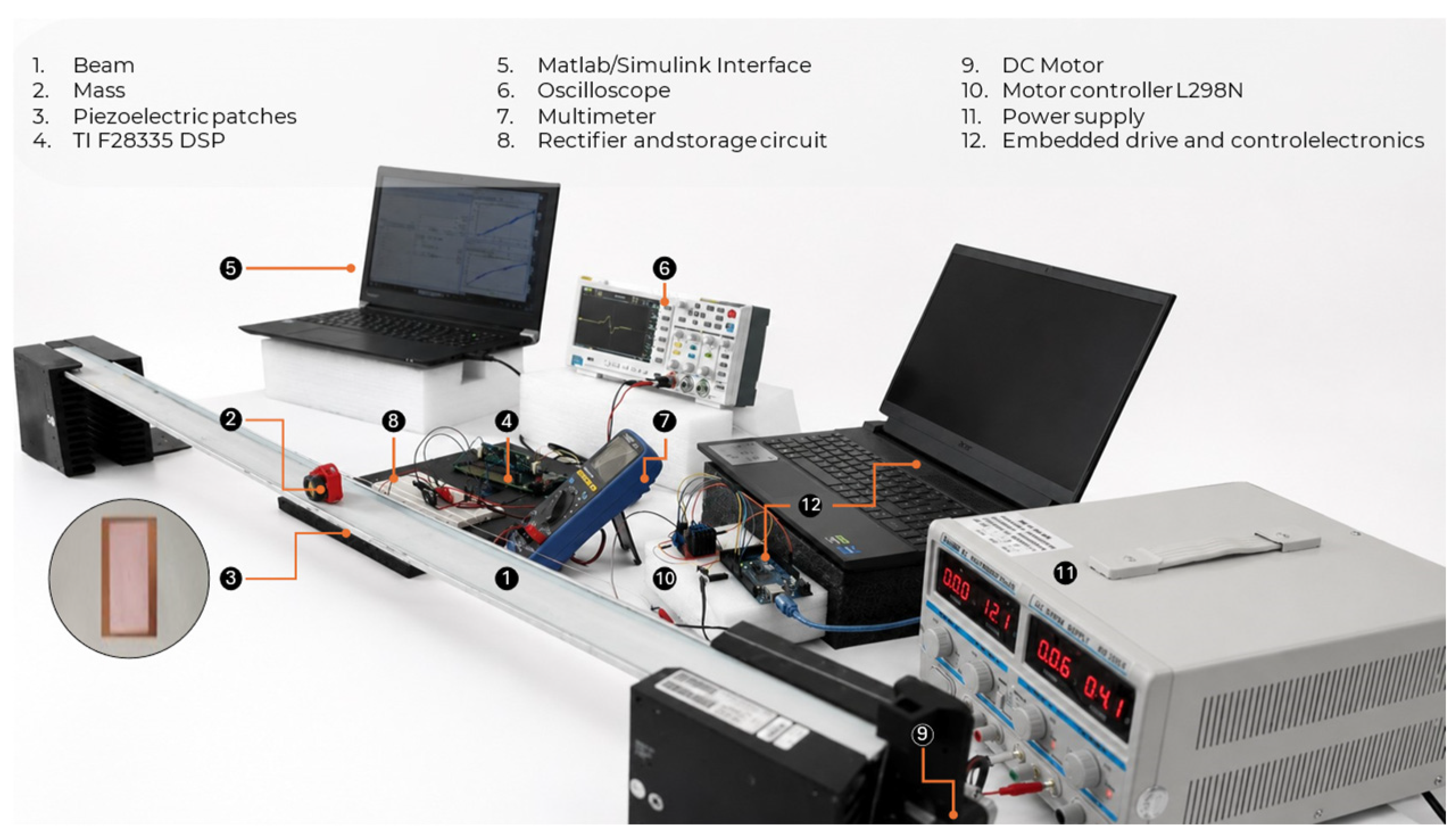
The complete experimental device, illustrated in
Figure 19, is organized into three coupled subsystems:
The mechanical subsystem, including the beam, the moving mass and the piezoelectric patches.
The moving-mass drive subsystem, including a DC motor, a motor driver, a regulated DC power supply and the associated control electronics, which together ensure a controlled translation of the mass along the beam.
The cylindrical moving mass rests directly on the upper surface of the beam, in continuous sliding contact with it; both surfaces are smooth, resulting in a near-negligible friction force during transit. The mass is pulled along the beam by a thin wire wound around a pulley mounted on the motor shaft. As the motor rotates, the wire is reeled in or paid out, translating the mass along the beam axis, and the lateral alignment is maintained by the wire tension, which keeps the trajectory along the beam. The motor is driven through an L298N motor driver, allowing either a fixed or a variable transit speed to be prescribed. The two ends of the beam are clamped to the test bench by directly screwing them into a rigid, massive support, providing the clamped–clamped boundary condition assumed in the semi-analytical and numerical models.
The acquisition and measurement subsystem, made up of a host computer, a digital oscilloscope, the rectification and storage circuit and the DSP board, used to record the voltages and currents generated during each test.
The experimental test bench is composed of a clamped–clamped beam carrying a moving mass and instrumented with one or two rectangular PZT piezoelectric patches bonded to its lower surface. The patches are placed in the high-curvature zone close to mid-span where the modal strain induced by the traversing mass is largest. For the two-patch tests, several values of were considered in order to investigate the effect of the inter-patch spacing on the electromechanical response of the system.
The beam is connected to a moving-mass drive system including a DC motor, a regulated DC power supply and embedded drive and control electronics. The motion of the mass is controlled in real time through a Texas Instruments TMS320F28335 DSP board interfaced with MATLAB/Simulink, which simultaneously records the electrical response generated by the piezoelectric patches during the experiments.
6.1. Experimental Results
The measured voltage is compared with the semi-analytical and COMSOL results for the same case: a clamped–clamped beam with
, the same load resistance
, and the parameters given in
Table 2. The compared quantity is the AC voltage across the load resistance, which corresponds to Equation (37).
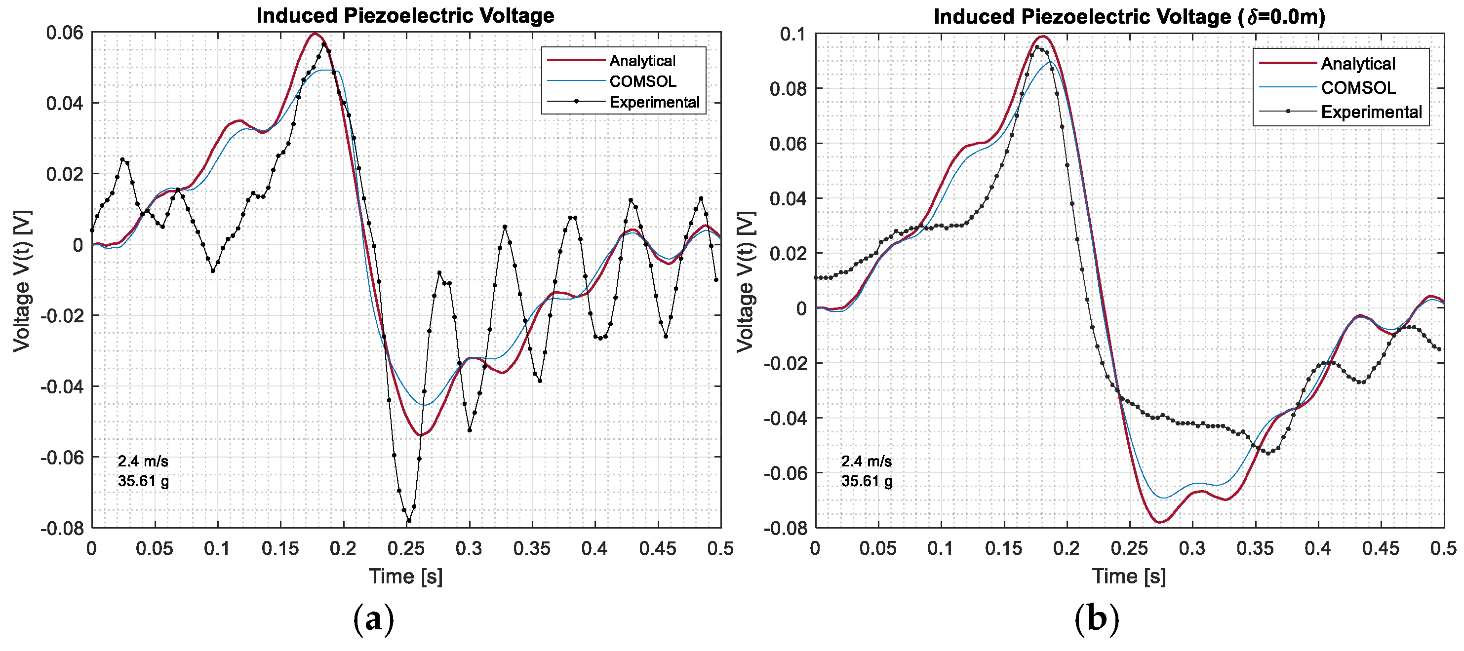
Figure 20 compares the semi-analytical results, the COMSOL simulations and the experimental measurements obtained for the clamped−clamped configuration with one and two patches at
with
. The main features of the voltage signal are well captured by the model, including the timing of the peaks and the overall trend of the response. The experimental signal does carry some noise and small amplitude jumps, but these come from the test setup, not the model, such as parasitic vibrations of the supporting frame, imperfect bonding of the piezoelectric patches, electrical noise on the acquisition chain, the fact that the mass does not move at exactly a constant speed, and local nonlinearities. Despite these disturbances, the model and the experiment agree closely enough and confirm that the proposed model accurately predicts the electromechanical response under realistic operating conditions. So, the model can be used to study the performance of the clamped harvesters.
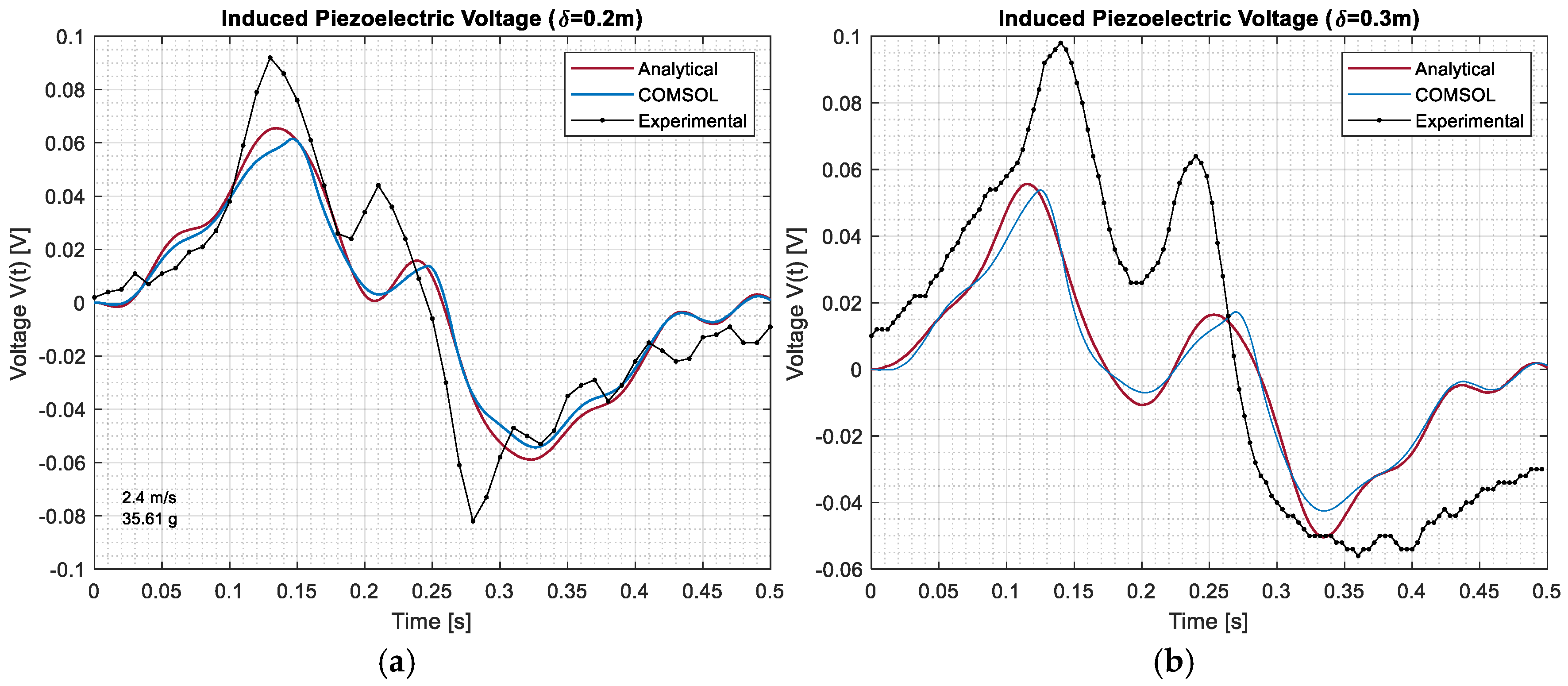
Figure 21 shows the comparison obtained for the two-patch configuration with inter-patch distances of
and
, with
. In all cases, the experimental response follows the same trend of positive and negative peaks as the semi-analytical and COMSOL results, and all three responses agree well enough to confirm that the proposed model captures the influence of the separation gap on the voltage output. The measured peaks are a bit higher than the predicted ones, which suggests that the actual strain field in the beam may be locally more intense than the field reproduced by the semi-analytical model. The trends are consistent, and the formulation is validated. The results also clearly show that the gap between the patches has a strong effect on both the size of the voltage and its shape over time;
can therefore be assessed as a key design parameter for the optimization of multi-patch piezoelectric energy harvesters.
The relative error in the peak voltage amplitude, which is the quantity for which the disagreement between the analytical, numerical, and experimental results is most pronounced, was estimated for each tested configuration, and the results are summarized in
Table 4. This discrepancy is mainly attributed to the stronger oscillatory behavior and residual vibrations observed in the experimental response, which are not fully captured by the reduced-order semi-analytical model.
In all tested cases, the semi-analytical, numerical, and experimental responses exhibit good agreement regarding the occurrence of the main voltage peaks, indicating a negligible phase shift between the predicted and measured responses.
Measurement uncertainty is expected to arise mainly from sensor noise, data acquisition resolution, and variations in the moving-mass trajectory between passages. The repeated tests conducted in this study provide a first qualitative assessment of this variability, which remained within the noise level visible in
Figure 20 and
Figure 21.
6.2. Electronic Energy Harvesting Circuit
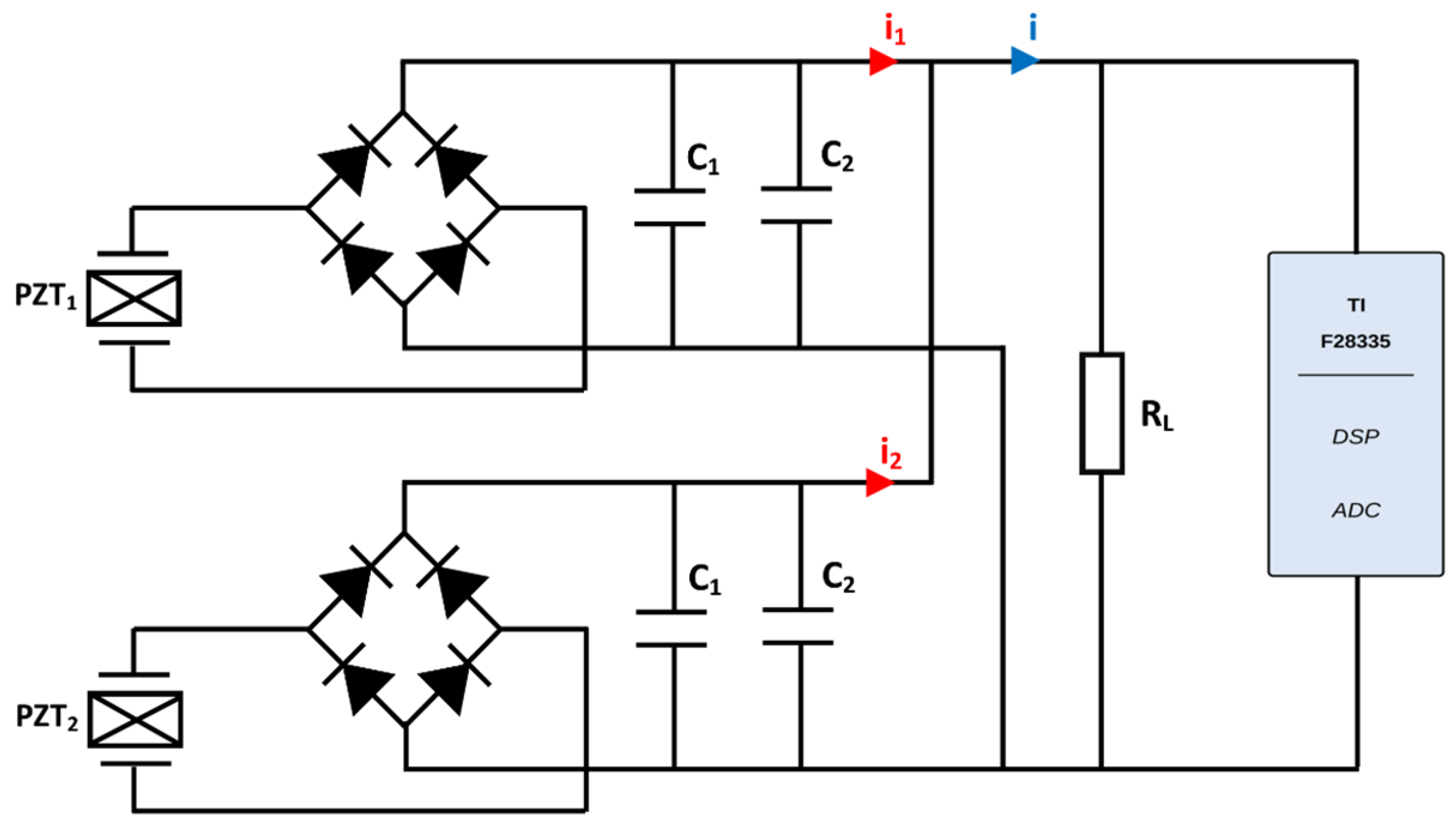
The electronic circuit converts the alternating voltage delivered by the piezoelectric patches into a stabilized DC voltage stored across the load. Its topology is depicted in
Figure 22. Each piezoelectric patch (PZT1 and PZT2) is connected to its own full-wave rectifier bridge built from four 1N5711 Schottky diodes. Schottky diodes were preferred to standard silicon rectifiers because of their low forward voltage drop
, which limits the rectification losses that are particularly detrimental at the small voltage amplitudes typical of piezoelectric harvesters and therefore improves the overall conversion efficiency.
At the output of each bridge, the rectified signal feeds a local storage stage made of an electrolytic capacitor
in parallel with a ceramic capacitor
. The electrolytic capacitor accumulates the harvested charge and constitutes the energy reservoir of the channel, while the ceramic capacitor suppresses the high-frequency components and reduces the residual voltage ripple of the rectified signal. Independent storage stages are used per channel to prevent reverse current flow between branches when the two rectified voltages are unequal. The two channels’ DC outputs are then combined in parallel, so that the load current is
The resistive load is connected across the combined DC bus and represents the equivalent input impedance of the targeted low-power electronic load. The voltage across is digitized by the analog-to-digital converter of the TMS320F28335 DSP board and streamed in real time to MATLAB/Simulink for further analysis.
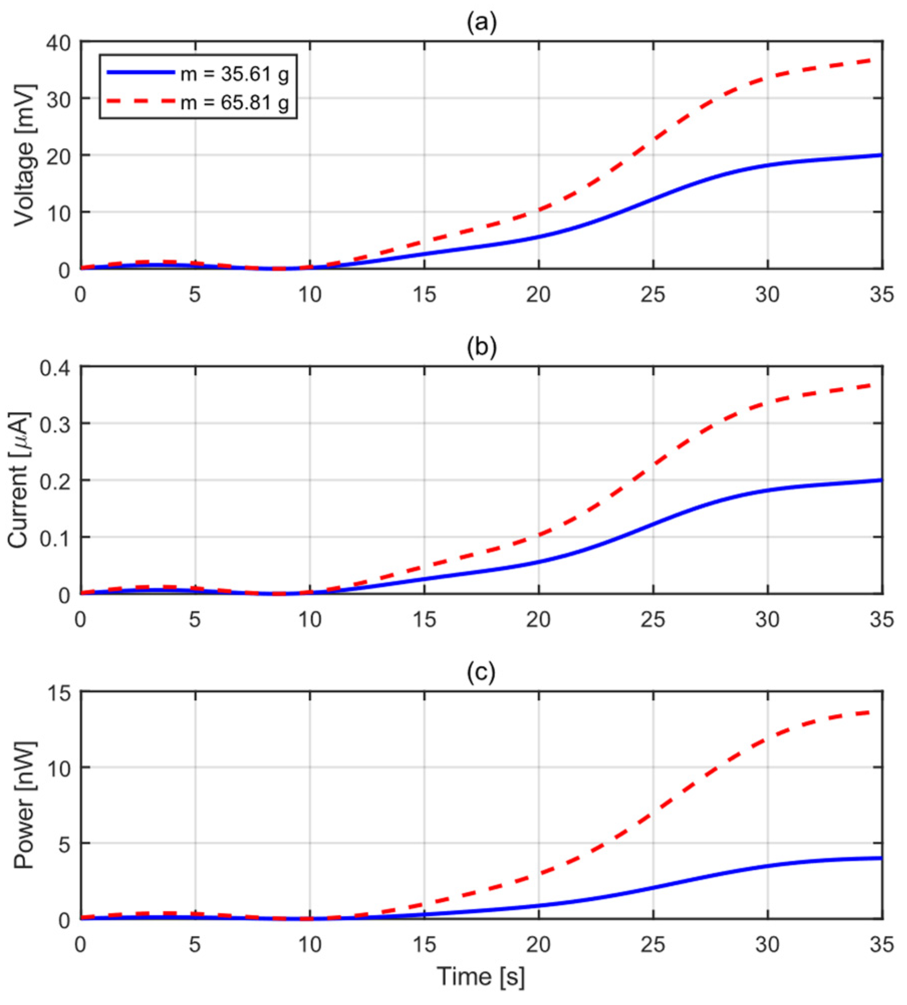
Figure 23 shows the voltage, current, and stored power across the resistive load
during a
charging period for each of the two mass values
operating at one back-and-forth pass per second. The voltage across
reflects the charge accumulated in the storage capacitor
of a single active patch. For both masses, this voltage climbs steadily over time, which indicates that the energy generated by the piezoelectric patch is effectively rectified and accumulated at each passage of the mass. The heavier mass produces a higher strain level in the beam and leads to a larger generated voltage and a faster charging rate. At
, the voltage across
reaches approximately
for
and
for
, while the harvested power reaches about
and
, respectively, confirming that the heavier mass produces nearly twice the stored voltage and more than three times the harvested power. The current and the instantaneous power follow the same trend, gradually rising before approaching a slower growth rate as the voltage across
approaches its steady-state value. This behavior confirms the capability of the proposed harvesting system to convert the repetitive mechanical excitation generated by the moving mass into usable electrical energy and demonstrates that the recovered energy can be stored for later use, such as powering small electronics, for example, a wireless sensor node for structural health monitoring.
7. Conclusions
In this paper, a vibration energy harvester based on beams with piezoelectric patches was elaborated and investigated using semi-analytical, numerical based on COMSOL and experimental approaches. A generalized electromechanical model for piezoelectric energy harvesting is elaborated for beams subjected to a moving mass. The model accounts for several key physical effects that are often neglected in conventional formulations. The model incorporates the influence of moving-mass acceleration, multiple piezoelectric patches, different boundary conditions, and geometric nonlinearity. The governing equations were derived using a modal decomposition approach, leading to a reduced-order nonlinear system that captures the coupled dynamics between the beam and the electrical circuit. The inclusion of geometric nonlinearity introduces amplitude-dependent stiffness through cubic modal coupling, while the acceleration of the moving mass modifies the transient excitation and alters the beam response. The semi-analytical results showed that the number of retained modes plays an important role for accurately predicting the voltage response, especially in the regions where higher curvature effects are important. An experimental test-bench has been set up using a motor-driven moving mass. The experimental validation performed on the clamped–clamped beam confirms the ability of the proposed model to predict both the transient voltage response and the effect of patch spacing. Good agreement between semi-analytical and numerical predictions with measured responses was observed. Therefore, the proposed framework provides a more comprehensive basis for the analysis and design of piezoelectric energy harvesters subjected to moving masses.
The main findings are as follows. The harvested electrical output is mainly governed by the boundary conditions, the patch configuration, and the motion properties of the moving mass. The clamped–clamped configuration significantly alters the strain distribution along the beam, and multiple patches, when properly distributed, improve energy extraction. The number of retained modes was found to be critical for accurately predicting the voltage response, particularly in regions where higher-curvature effects dominate, since the induced voltage is more sensitive to higher modes than the displacement.
On the other hand, the present model does not capture the contact effect of the moving mass on the patch, nonlinear piezoelectric behavior, nonlinear electromechanical coupling, or patch cracking and debonding. These effects are the focus of future work.