1. Introduction
With the rapid development of the Internet of Things and wireless sensor networks, self-powered technology has become a key approach to addressing the energy demands of microelectronic devices [
1,
2,
3,
4]. Among the four common mechanisms for mechanical-to-electrical energy conversion—electrostatic [
5], electromagnetic [
6], piezoelectric [
7,
8,
9,
10], and triboelectric [
11]—the piezoelectric mechanism stands out as a particularly promising power solution. This is due to its high power density, low cost, minimal energy loss, and ease of assembly, making it especially attractive [
12].
As the core component of piezoelectric energy harvesting, cantilever beam structures have been extensively studied due to their efficient mechanical coupling characteristics and environmental vibration adaptability. Research has progressed from the development of composite materials such as lead zirconate titanate (PZT) to polyvinylidene fluoride (PVDF) [
13,
14,
15,
16], to structural optimization designs including variable-cross-section beams [
17], multi-segment structures [
18], and bending–torsion coupling designs [
19]. Compared with piezoelectric material development, structural optimization design has become a more efficient approach for performance enhancement, offering lower cost, shorter development cycles, and greater design freedom. This makes it particularly suitable for engineering applications and research requiring rapid iteration.
Recently, some researchers have introduced auxetic structures to improve the efficiency of energy harvesters [
20,
21,
22,
23,
24,
25,
26,
27]. These structures are characterized by a negative Poisson’s ratio, meaning they expand laterally under extension and contract laterally under compression. Due to this unique property, auxetic structures have been studied for sensing [
28], actuation [
29], and impact absorption [
30]. However, their complex geometries combined with current limitations in cost and precision of three-dimensional (3D) printing technology in China present manufacturing challenges. Hajhossseini and Rafeeyan [
31] employed the generalized differential quadrature rule (GDQR) method to investigate a bimorph piezoelectric cantilever beam with periodically variable cross-sections. Their work strategically leveraged the concept of phononic crystals to create band gaps, effectively broadening the operational frequency bandwidth for vibration energy harvesting. While this approach successfully achieved a higher output voltage over a broader frequency range compared to uniform beams, it necessitates precision machining techniques such as laser cutting or micro-milling, which inevitably increase manufacturing costs by 30–50%. To address the direction sensitivity of conventional harvesters, Ren et al. [
32] proposed a multi-directional device comprising a lower arc-shaped beam and an upper L-shaped beam. The synergistic interaction between these beams enabled energy harvesting from various vibration directions. A key feature of their design was utilizing the L-shaped beam also as a proof mass to lower the resonant frequency. However, this innovative configuration amplifies stress concentrations at the beam’s root, making the structure more susceptible to fatigue failure, which poses a significant challenge for long-term reliability. Another effective strategy to enhance performance focuses on actively modulating the neutral axis position. For instance, Wang and Xu [
33] adopted an air-spaced cantilever beam structure to increase the distance between piezoelectric layers and the neutral plane, thereby achieving higher output voltage and conversion efficiency. Similarly, Rami et al. [
34] introduced cavities into the cantilever beam substrate to shift the neutral axis, reporting a remarkable 75% increase in output voltage compared to conventional structures. Their work provided valuable theoretical and experimental insights into how cavity parameters (position and thickness) regulate performance. Nevertheless, creating such precise air gaps or cavities within already thin substrates imposes stringent requirements on machining precision and material integrity, potentially limiting their widespread application and increasing fabrication complexity.
While the aforementioned studies have demonstrated various effective strategies for enhancing the performance of piezoelectric energy harvesters, such as employing auxetic structures [
20,
21,
22,
23,
24,
25,
26,
27], periodic variable cross-sections [
31], multi-directional beams [
32], and air-spaced or cavity designs [
33,
34], they often entail inherent limitations. Specifically, auxetic and complex geometric structures are hampered by manufacturing challenges and high costs associated with current 3D printing technologies. Precision-machined variable cross-sections significantly increase production expenses. Designs incorporating proof masses aggravate stress concentration and fatigue risks. Although cavity designs effectively modulate the neutral axis, they impose stringent requirements on machining precision and material integrity for already thin substrates. In distinct contrast to these approaches, this study proposes a novel, cost-effective, and process-compatible strategy: surface arrayed groove modulation on the substrate of a piezoelectric cantilever beam. The principal novelty of this work is threefold: 1. Systematic Investigation of Groove Coupling Mechanisms: It delves beyond mere neutral axis shift, for the first time explicitly revealing and analyzing the coupling mechanism between stiffness modulation, Local resonance instability phenomenon, and energy conversion in grooved piezoelectric harvesters, which is often overlooked in prior art. 2. Active Suppression of Local resonance instability phenomenon via Arrayed Design: Moving beyond single grooves which easily induce detrimental Local resonance instability phenomenon, we propose an arrayed groove configuration that uniformly distributes stiffness reduction. This design effectively suppresses Local resonance instability phenomenon (maintaining amplitudes below 5% compared to >15% in single grooves), thereby preventing energy dissipation and unlocking greater performance enhancement. 3. Superior Performance with Uncompromised Practicality: The optimized arrayed groove design achieves a significant voltage output improvement (17.3% increase) without inducing narrow-bandwidth effects. Crucially, this is achieved using conventional machining methods (e.g., milling), offering exceptional process compatibility and an estimated 30–45% cost reduction compared to additive manufacturing or precision machining techniques required by other advanced designs. This work provides a practical and highly efficient optimization pathway distinguishable from previous studies.
Therefore, this paper aims to develop a design method based on surface arrayed groove modulation. Through arrayed grooving, the proposed approach effectively suppresses Local resonance instability phenomenon while optimally regulating the neutral axis position. This solution maintains the process compatibility of conventional cantilever beams, reduces technical requirements, and simultaneously enhances energy conversion efficiency. The remaining sections of this paper are organized as follows:
Section 2 presents the design and introduces the basic structure of the piezoelectric cantilever beam, along with the simulation procedures and relevant theoretical foundations.
Section 3 comparatively studies the power generation performance of three groove configurations: upper surface grooving, lower surface grooving, and double-sided grooving on the substrate. Building upon
Section 3,
Section 4 proposes an arrayed groove solution to systematically address Local resonance instability phenomenon issues caused by excessive grooving, while analyzing its energy harvesting characteristics to achieve optimization goals. Finally,
Section 5 summarizes the research findings and elaborates on the main contributions.
2. Structural Design
The baseline configuration proposed in this study is illustrated in
Figure 1. The model consists of an aluminum substrate (120 mm × 10 mm × 2 mm) and piezoelectric patches. Each piezoelectric patch comprises a beryllium bronze layer (60 mm × 10 mm × 0.2 mm) with a centrally positioned PZT-5H layer (40 mm × 10 mm × 0.2 mm), featuring 10 mm beryllium bronze extensions at both ends. The finite element model employs SOLID5 elements with mapped meshing, where the PZT-5H is assigned piezoelectric properties with its bottom surface set as the zero-potential reference. A 12 mm-long section at the model’s left end is designated as the fixed boundary, with piezoelectric patch bonding commencing 1 mm from the fixed end to prevent stress concentration. The right end remains as the free end, and a 1 mm Z-direction displacement excitation applied at the fixed end induces forced vibration in the cantilever beam, thereby achieving mechanical-to-electrical energy conversion through the direct piezoelectric effect.
This study employs ANSYS finite element analysis software (Version 2022 R1) to conduct simulation analysis of the proposed piezoelectric cantilever beam energy harvester. The relevant geometric and material parameters involved in this research are listed in
Table 1 and
Table 2, respectively.
The elastic constant matrix of PZT-5H is expressed as:
The piezoelectric constant matrix of PZT-5H is given by:
The dielectric constant matrix of PZT-5H is defined as:
This research conducts in-depth simulation analysis to investigate how groove processing on the substrate surface of piezoelectric cantilever beams can optimally regulate neutral axis offset and avoid Local resonance instability phenomenon to maximize voltage output performance without affecting bandwidth. Bandwidth refers to the frequency range within which the piezoelectric cantilever beam can maintain effective operation under specific performance indicators (such as output power, voltage sensitivity, or vibration response amplitude). It is typically quantified by the frequency interval between half-power points (the −3 dB points of peak response). The −3 dB point corresponds to the frequency at which the system response amplitude (voltage, power, or displacement) decreases to 0.707 times (70.7%) the peak amplitude.
The bandwidth calculation formula in this study is:
where
f1 and
f2 represent the lower and upper cutoff frequencies when the response amplitude decreases to 70.7% of the peak value. The neutral axis is a hypothetical axis of the beam during bending deformation. In downward bending cases, the portion above the neutral axis experiences tension, while the portion below undergoes compression. Its position depends on the beam’s cross-sectional geometry and material properties (such as elastic modulus). For piezoelectric cantilever beams, the neutral axis typically shifts toward the side with higher stiffness or greater thickness. The power generation capability (output voltage/power) of piezoelectric cantilever beams is closely related to the relative positions of the piezoelectric layer and the neutral axis. When the piezoelectric layer is farther from the neutral axis, the piezoelectric effect strengthens; when closer, the effect weakens. Current common methods for optimizing neutral axis position include: adjusting material stiffness, modifying thickness ratios, and employing multilayer structural designs. This study will investigate the influence of neutral axis position on the power generation performance of piezoelectric cantilever beams through thickness ratio modification and multilayer structural design approaches.
Local resonance instability phenomenon refers to a phenomenon where a specific localized region of the piezoelectric cantilever beam (such as an added mass, particular structural layer, or defective area) exhibits significantly amplified vibrational response at certain frequencies, while other regions demonstrate weaker vibrations. During energy harvesting, the occurrence of Local resonance instability phenomenon typically leads to energy dissipation and structural fatigue in piezoelectric cantilever beams. Therefore, when performing groove processing on the substrate surface of piezoelectric cantilever beams, the potential emergence of Local resonance instability phenomenon and its prevention constitute critical factors that cannot be neglected.
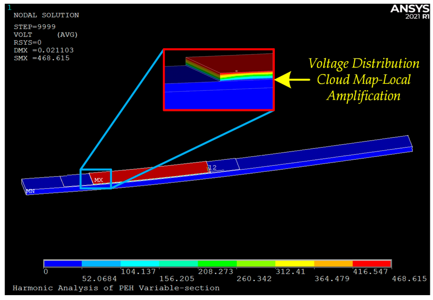
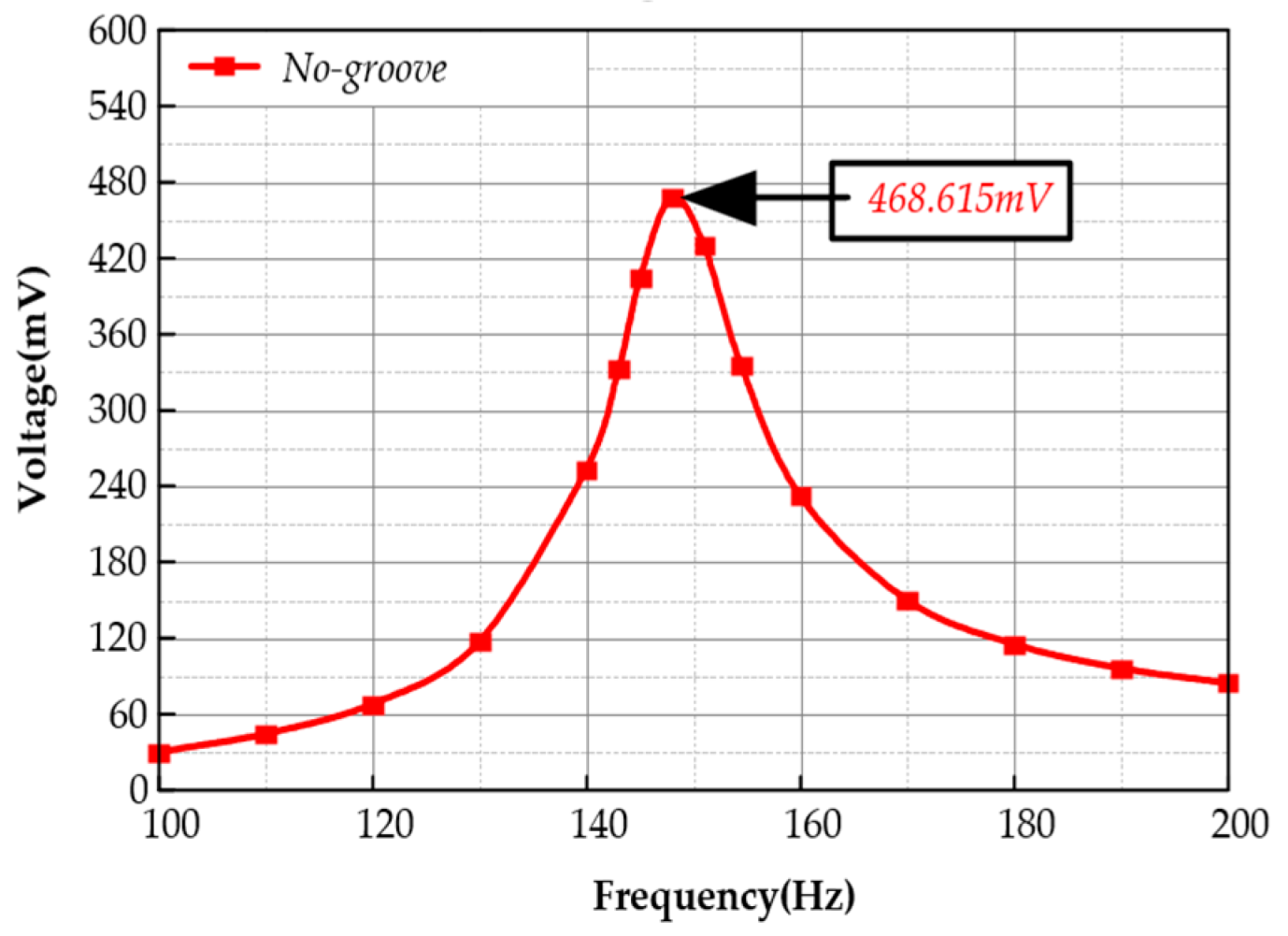
The voltage output contour plot and data results obtained from the simulation of the baseline configuration are shown in
Figure 2 and
Figure 3, respectively. This configuration achieves a peak voltage of 468.615 mV at 147.9 Hz, with a neutral axis offset of 0 and a bandwidth of 11.5 Hz, demonstrating no occurrence of Local resonance instability phenomenon. In subsequent analyses, we will use this model as the reference to perform groove processing on the substrate surface of the piezoelectric cantilever beam, conducting in-depth simulation studies on multiple configurations. The detailed content will be thoroughly presented in the following chapters.
3. Single Groove Configuration
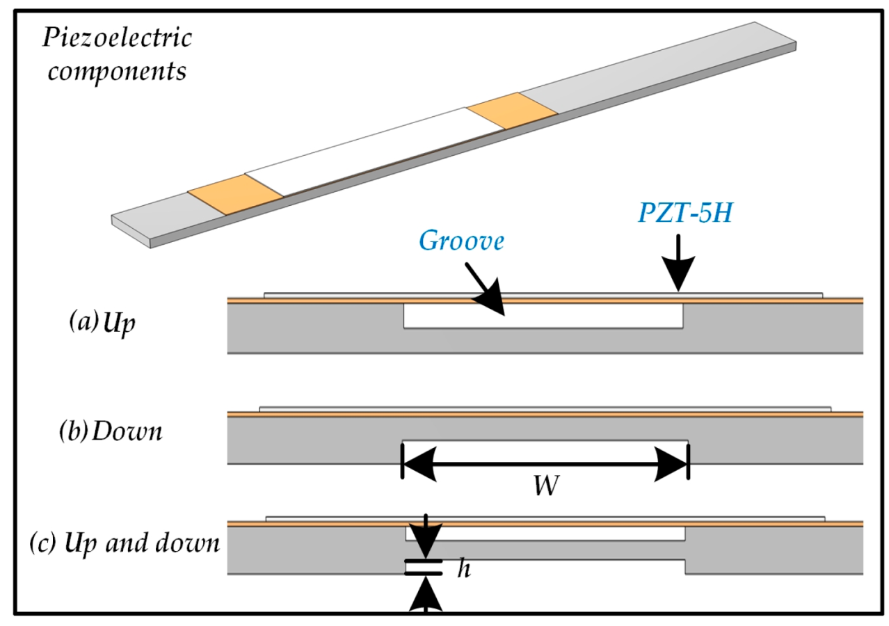
In this section, we investigate the effects of single groove configurations (upper surface, lower surface, and double-sided grooves) at different locations on the substrate surface of piezoelectric cantilever beams on power generation performance. The schematic diagrams of each configuration are shown in
Figure 4. Through parametric analysis methods, we systematically examine the influence patterns of groove width W (10/20/30/40 mm) and groove depth h. The groove depth variation ranges are 0.2–1.8 mm for upper and lower surface grooves, and 0.2–0.8 mm for double-sided grooves, with a 0.2 mm interval between adjacent gradients.
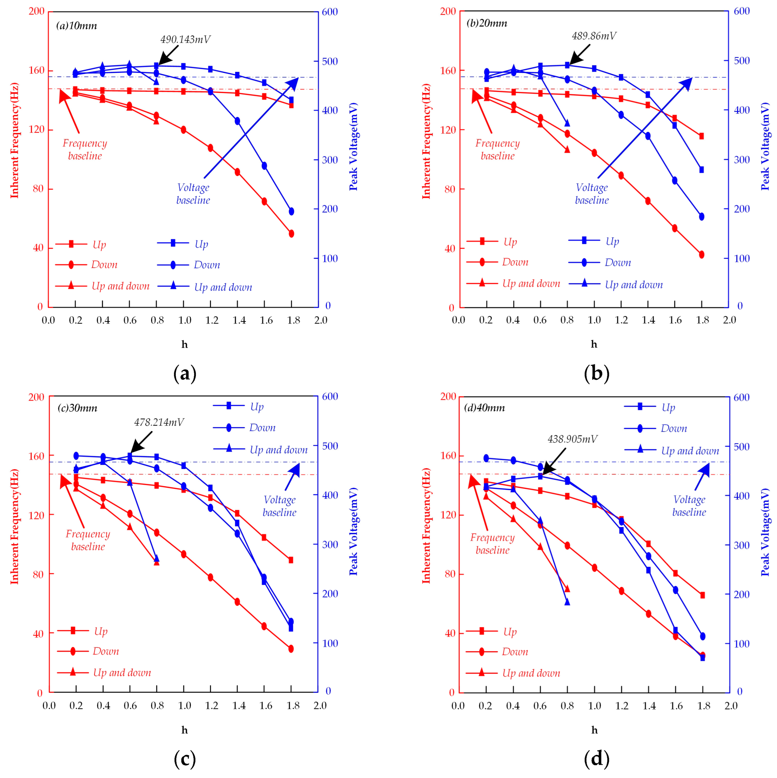
The simulation results are shown in
Figure 5, which records the inherent frequencies and corresponding peak voltages for each configuration under different groove widths W and groove depths h. The output voltage clearly exhibits nonlinear variation with groove depth. Notably, in all four subplots (a, b, c, d), whether for upper surface, lower surface, or double-sided grooves, the output voltage monotonically decreases with increasing groove width at fixed groove depth—a phenomenon that cannot be reasonably explained solely from the perspective of neutral axis position offset.
Focusing on the simulation results for upper surface grooving on the substrate, theoretical analysis of neutral axis behavior suggests that for configurations with grooves on the upper surface, the neutral axis should progressively move away from the piezoelectric patch as groove width and depth increase. Upon reaching a certain critical value, the neutral axis position transitions from moving away from to moving toward the piezoelectric patch. This transition manifests in the voltage output simulation results as gradually diminishing enhancement effects, ultimately exhibiting inhibitory effects (compared to the output voltage of the ungrooved configuration).
However, when the groove depth is 0.8 mm and the groove width increases from 10 mm to 20 mm, the neutral axis position continues to shift away from the piezoelectric patch (which should theoretically increase output voltage), yet the simulation results show the output voltage decreases from 490.143 mV to 489.86 mV. Similarly, at a groove depth of 0.6 mm when the groove width increases from 30 mm to 40 mm, while the neutral axis maintains its movement away from the piezoelectric patch, the output voltage drops from 478.241 mV to 438.905 mV. Both simulation results contradict the neutral axis theory, with the voltage reduction becoming more pronounced as groove width increases. Particularly at 40 mm groove width, though the neutral axis position has shifted farther from the piezoelectric patch compared to the ungrooved configuration, the output voltage measures only 438.905 mV—showing significant suppression relative to the ungrooved configuration’s 468.615 mV. Therefore, we conducted modal analysis on the 40 mm groove width piezoelectric cantilever beam.
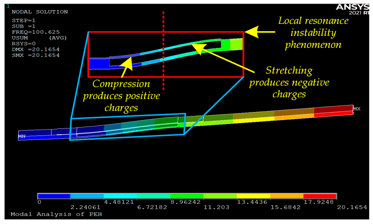
Figure 6 shows the modal shape at the resonant frequency for the beam with a 40-mm-wide groove. It can be observed that the deformation is highly concentrated in the grooved region, while the rest of the beam undergoes much smaller deformation. Moreover, the PZT-5H corresponding to the grooved area shows a phenomenon where the front part is compressed and the rear part is stretched. This phenomenon causes the front part of the PZT-5H to generate positive charges and the rear part to generate negative charges, resulting in mutual neutralization of positive and negative charges. This is the fundamental reason for the low energy conversion efficiency and also explains the voltage suppression observed in
Figure 5d. In this context, ‘Local resonance instability phenomenon’ refers to the phenomenon where, under the global resonant mode, a specific region (e.g., the grooved area) exhibits disproportionately large vibrational amplitude and strain concentration compared to the rest of the structure, leading to the PZT-5H simultaneously experiencing both compression and stretching states. This results in the generation of positive and negative charges that neutralize each other, ultimately causing low energy conversion efficiency.
The simulation results (
Figure 6) reveal localized resonance phenomena occurring precisely in the grooved regions. This provides a physical explanation for the observed phenomena: the progressive voltage reduction from 10 mm to 40 mm groove widths correlates directly with intensifying Local resonance instability phenomenon effects. As groove width increases, local stiffness continuously decreases, amplifying Local resonance instability phenomenon and consequently exacerbating energy dissipation—ultimately manifesting as output suppression.
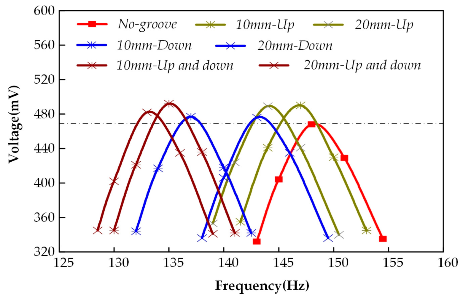
Subsequently, we conducted a comparative study on the bandwidth of single-groove configurations. Considering the significant Local resonance instability phenomenon phenomena observed at 30 mm and 40 mm groove widths, the bandwidth comparison was performed only for 10 mm and 20 mm groove widths. For each width, we selected the configuration (among upper surface, lower surface, and double-sided grooves) that yielded the maximum voltage output for bandwidth analysis. The comparison results (
Figure 7) demonstrate that surface grooving has negligible impact on bandwidth. With no Local resonance instability phenomenon occurring, the neutral axis theory dominates the output voltage characteristics. While lower surface grooving achieves larger amplitudes through reduced stiffness, the simultaneous movement of the neutral axis closer to the piezoelectric patch results in minimal net voltage enhancement. Double-sided grooving shows little neutral axis displacement, but the data labeled “20 mm-Up and down” in
Figure 7 indicates that increasing groove width and depth advances the critical point for Local resonance instability phenomenon onset, which adversely affects voltage output improvement.
Therefore, we conclude that upper surface grooving (on the side closest to the piezoelectric patch) yields optimal results. However, selecting smaller grooves to avoid Local resonance instability phenomenon leads to minimal changes in overall substrate stiffness and neutral axis offset, resulting in insignificant voltage output enhancement. Further optimization design is still required. These phenomena reveal the coupled mechanism of stiffness modulation-Local resonance instability phenomenon-energy conversion in groove design. Specific optimization methods will be addressed in subsequent sections through an arrayed grooving strategy.
4. Arrayed Groove Configuration
To achieve the objectives of reducing stiffness in the piezoelectric cantilever beam, increasing neutral axis offset, and preventing Local resonance instability phenomenon, this section conducts a comparative study implementing arrayed groove processing on the upper surface. The study defines: Number of grooves: N; Groove width: W
1; Spacer width: W
2, and introduces a new parameter α = groove width/spacer width (α = W
1/W
2). This chapter is divided into two parts for discussion. The first part keeps the number of grooves N = 3 constant, selecting α = 1 with W
1 = 8 mm, α = 2 with W
1 = 10 mm, and α = 6 with W
1 = 12 mm to investigate their power generation performance. The second part keeps α = 2 constant, selecting N = 7 with W
1 = 4 mm, N = 3 with W
1 = 10 mm, and N = 2 with W
1 = 16 mm to investigate their power generation performance. All groove depths (h) are set in gradients (0.2–1.8 mm, with 0.2 mm intervals) to maintain consistency with previous research. The schematic diagram of the basic configuration energy harvester is shown in
Figure 8.
4.1. Performance Analysis with Constant Groove Count (N = 3)
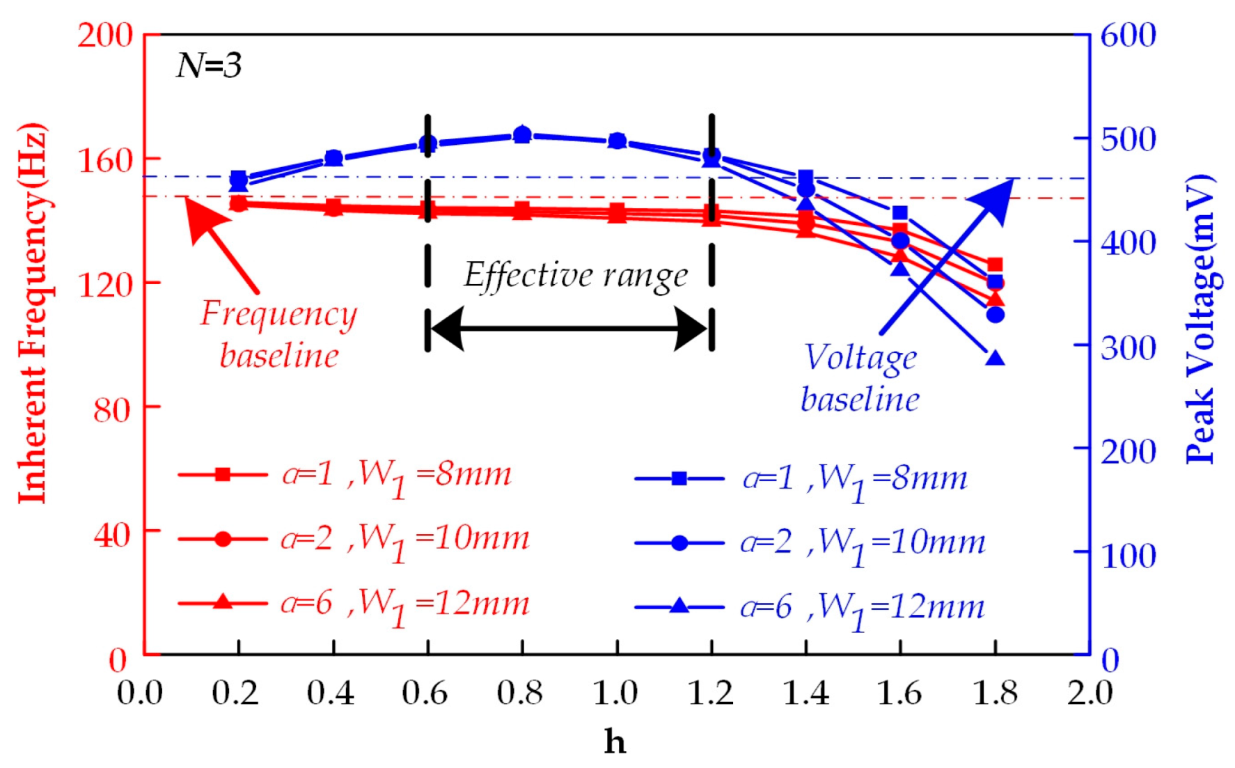
Figure 9 presents the simulation results for array-grooved upper substrate surfaces (N = 3). Compared to the non-grooved structure, the optimized design demonstrates improved power generation performance. All configurations achieve maximum voltage output at a groove depth (h) of 0.8 mm, peaking at 503.5 mV (a 7.4% increase over the non-grooved structure). However, groove processing still exhibits suppressive effects on voltage output at specific depths: At h = 0.2 mm: Neutral axis offset away from the piezoelectric layer is insufficient to compensate for local stress reduction caused by grooving, resulting in output suppression. Within h = 0.4–1.2 mm range: Continuous neutral axis displacement from the piezoelectric layer enhances output voltage across all tested configurations. When h > 1.2 mm: Neutral axis regression coupled with intensified Local resonance instability phenomenon (amplitude > 15%) causes power output attenuation.
Therefore, we conclude that within the effective range (h = 0.4–1.2 mm), the power generation performance exhibits insensitivity to the groove-width-to-spacer-width ratio (α), with voltage differences among the three α configurations being <2.3%. This indicates that when N = 3, groove distribution compactness is not a critical influencing factor.
4.2. Performance Analysis with Fixed Groove-Width-to-Separation Ratio (α = 2)
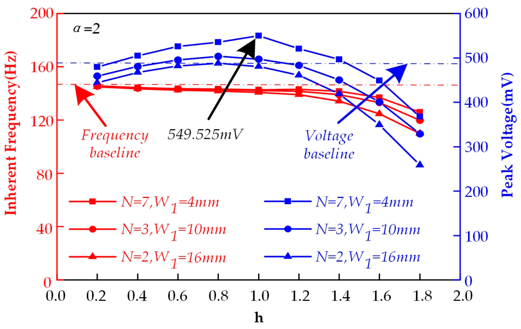
The simulation results of this part are shown in
Figure 10, comparing the power generation performance of three groove widths (W
1 = 4 mm, 10 mm, 16 mm) under fixed α = 2 condition.
It was found that for W1 = 10 mm and W1 = 16 mm configurations, due to relatively sparse groove distribution, the maximum output voltages of 503.5 mV and 487.769 mV were significantly lower than those of the W1 = 4 mm configuration. The W1 = 4 mm arrayed groove configuration demonstrated optimal performance, maintaining output voltages above 500 mV throughout the groove depth range of h = 0.4–1.2 mm, and achieving a peak voltage of 549.525 mV at h = 1 mm (representing a 17.3% improvement compared to the non-grooved structure). Additionally, the W1 = 4 mm configuration exhibited excellent stability with output voltage fluctuations less than 2% at h = 0.8 mm depth.
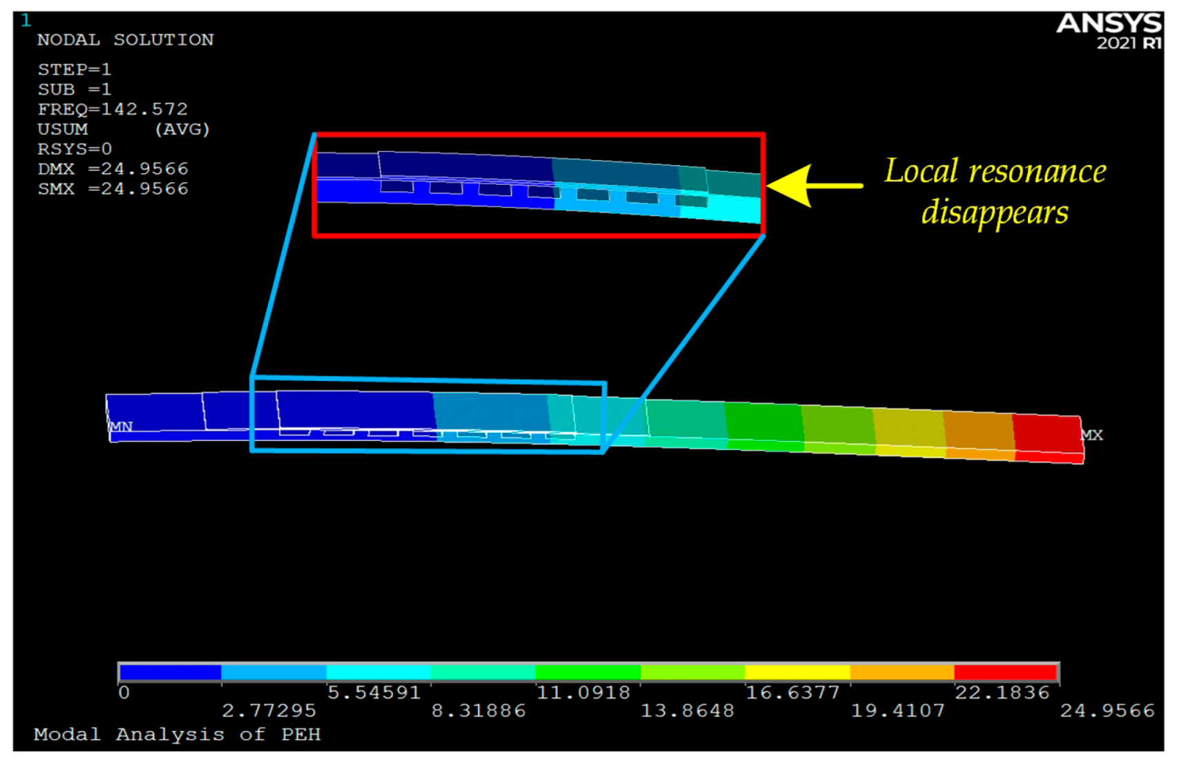
Compared with single-groove configurations, the arrayed groove design avoids abrupt local stiffness reduction through uniform groove distribution. As shown in
Figure 11, the Local resonance instability phenomenon amplitude in the W
1 = 4 mm, h = 1 mm configuration remains below 5%, significantly lower than that of single-groove designs (amplitude > 15%).
Therefore, we conclude that the 7-groove array configuration (W
1 = 4 mm, h = 1 mm) on the upper substrate surface (closest to the piezoelectric patch side) demonstrates optimal voltage output performance. The increased groove count (N = 7) enables more uniform neutral axis displacement. Although individual groove width is smaller, the overall stiffness reduction remains moderate, resulting in superior stability in voltage output characteristics. The peak voltage reaches 549.525 mV, representing a 17.3% increase compared to the non-grooved configuration. Notably, no bandwidth narrowing occurs due to the grooving process, confirming that the frequency response range remains unaffected. The corresponding voltage output contour plots and comparative data results are shown in
Figure 12 and
Figure 13, respectively.
5. Discussion and Future Work
While the present study primarily relies on a well-validated finite element model to investigate the underlying mechanisms of arrayed groove modulation, the simulation approach offers several advantages for initial design and optimization. The use of ANSYS software with high-fidelity SOLID5 elements and mapped meshing ensures computational accuracy. The material properties and boundary conditions are set to closely mimic realistic scenarios, as detailed in
Section 2.
The main limitations of the current work lie in the lack of physical prototype testing to directly measure the output voltage and frequency response under controlled excitation. Potential discrepancies between simulation and experiment could arise from factors such as minor imperfections in material properties, the idealized bonding layer assumption between the PZT and substrate, and damping effects from the surrounding environment which were not fully accounted for in the model.
Meanwhile, the introduction of grooves creates geometric discontinuities, which act as stress concentration points. Under long-term cyclic loading, these areas are potential initiation sites for fatigue cracks, ultimately potentially leading to structural failure. Future designs could mitigate this risk by incorporating rounded fillets at groove corners instead of sharp edges to reduce stress concentration factors, and by selecting fatigue-resistant materials—such as beryllium copper or high-strength aluminum alloys—for the grooved substrate.
The performance of the arrayed groove design, particularly its effectiveness in suppressing Local resonance instability phenomenon, is highly sensitive to geometric precision. Variations in groove depth, width, or surface finish during manufacturing (e.g., through milling or wire cutting) may deviate from the optimized simulation model, potentially resulting in performance degradation or unexpected resonant behavior. Close collaboration with manufacturing engineers and post-process metrology (e.g., using optical profilometers) are essential to ensure compliance with design specifications.
The long-term reliability of the energy harvester involves factors beyond the substrate itself. The integrity of the bonding layer between the piezoelectric patch and the grooved substrate is critical. Differential strain and potential debonding over time may reduce energy transfer efficiency. Furthermore, environmental factors such as temperature fluctuations, humidity, and dust intrusion can affect material properties and damping characteristics. Hermetic sealing or protective coatings may be necessary for operation in harsh environments.
Despite these limitations, the comprehensive parametric study and the clear, consistent trends observed in the simulation results provide strong theoretical evidence for the effectiveness of the proposed arrayed groove design.
The fundamental principle of this study is to suppress Local resonance instability phenomenon through distributed stiffness modulation while optimizing neutral axis offset, thereby endowing it with universal potential applicable across a broader design spectrum. The arrayed groove strategy can be adapted to other resonant structures, such as bridge-type, diaphragm-type, or cymbal-type energy harvesters. In these structures, controlling stress distribution and avoiding local modes are equally critical. Design parameters (number of grooves N, ratio α) serve as a flexible framework for adjusting the resonant frequency and strain energy distribution in such geometries.
Although an aluminum substrate was adopted in this study, the method is primarily mechanism-driven rather than material-specific. It can be extended to other common substrate materials, such as stainless steel (for higher fatigue resistance), polymers like PC or PI (for flexible electronics), or even composite materials. The key lies in recalibrating the groove parameters (depth, spacing) based on the Young’s modulus of the new material to achieve an ideal balance between stiffness reduction and structural integrity.
In biomedical sensors (e.g., implantable or wearable devices), a miniaturized version of this design could leverage its improved efficiency and stability to effectively harvest energy from body motion or ambient vibrations. In structural health monitoring (SHM), networks of such harvesters could be deployed on bridges, aircraft, or buildings to power sensor nodes. The arrayed groove design suppresses Local resonance instability phenomenon, providing higher reliability under variable and unpredictable ambient vibrations, thereby ensuring continuous energy generation for persistent monitoring.
Future work will explore these generalization pathways, with particular focus on miniaturization for biomedical applications and integration with SHM sensor networks. Thus, the results of this study can serve as a foundational step toward a more universal, high-performance, and manufacturable design paradigm for vibration energy harvesters.
6. Conclusions
This study systematically investigated the surface grooving configurations of piezoelectric cantilever beams and reached the following conclusions:
The upper surface, lower surface and double-sided slotted configurations with single-type notches have performance limitations. Although slotting can change the neutral axis position and reduce the stiffness of the piezoelectric cantilever beam to increase deformation, there are significant design defects. When the slot width is <20 mm, the maximum voltage increase is only 5.0%; when the slot width is >20 mm, the Local resonance instability phenomenon severely affects the voltage output performance.
The upper surface of the substrate (near the piezoelectric patch side) array slotted configuration under the fixed slot width–spacer ratio (α = 2) condition, with a smaller single slot width (W1 = 4 mm, h = 1 mm) combined with a higher slot number (N = 7), achieves a peak voltage of 549.525 mV, representing a 17.3% voltage output enhancement compared to the non-slotted condition. Through uniformly distributed slots that maximize neutral axis offset, it effectively suppresses the Local resonance instability phenomenon, avoids energy dissipation, and significantly increases output voltage while maintaining unchanged bandwidth. This result provides an important optimization direction for piezoelectric cantilever beam energy harvester design.
The research content of this paper is entirely based on slotting treatment applied to the substrate surface of piezoelectric cantilever beams. Through systematic analysis of the coupling mechanism among stiffness regulation, the Local resonance instability phenomenon, and energy conversion in slotting design, it provides reference and guidance for substrate surface slotting work. Meanwhile, since the piezoelectric element adopts an integrated bonding method using beryllium bronze and PZT-5H, it forms a composite sandwich structure with the aluminum substrate, effectively extending service life. This method demonstrates exceptional process compatibility, requiring only milling or wire cutting processing without additive manufacturing. Compared with toughened structures, this technology can reduce production procedures by 40–60%, while significantly decreasing technology and material costs by approximately 30–45%. It presents an alternative solution addressing current challenges in China where 3D printing technology and precision limitations make the fabrication of piezoelectric cantilever beams with metamaterial structures both costly and difficult.

