1. Introduction
Flow-induced vibration (FIV) is a critical aspect of fluid–structure interaction [
1], often resulting in uncontrolled oscillations that can adversely affect the performance and structural integrity of engineering systems. A wide range of applications is impacted by FIV, including offshore platforms, heat exchangers, aircraft wings, and high-speed trains. Excessive FIV can lead to fatigue, noise, instability, increased maintenance costs, and, in severe cases, structural failure [
2]. The phenomenon becomes increasingly unpredictable when vibrating structures are positioned in close proximity to one another, resulting in a mixed response governed by multiple underlying mechanisms. Thorough investigation is essential, given the sensitivity of the complex FIV phenomenon to structural characteristics, flow conditions, and the geometric arrangement. Accurately predicting the response of structures within an array presents a significant challenge for scientists and engineers striving for safety, performance, and system sustainability.
FIV encompasses various types of oscillations driven by distinct mechanisms, including vortex-induced vibration, buffeting, flutter, galloping, fluid-elastic instability, and acoustic-induced vibration. Vortex-induced vibration (VIV), as reviewed in references [
3,
4,
5,
6,
7], is linked to the process of vortex formation around slender structures. In this phenomenon, pressure variations in the wake generate periodic fluid forces, causing the structure to oscillate. These vibrations become particularly pronounced when the frequency of vortex formation approaches the natural frequency of the oscillating structure, leading to a temporary ‘lock-in’ of the vibration frequency and an increase in displacement amplitudes.
The lock-in condition, in terms of the displacement of structure, typically consists of initial and upper and lower (desynchronization) branches for a rigid structure with one degree of freedom (1DOF). Structures with two degrees of freedom (2DOF) exhibit larger displacement amplitudes than 1DOF structures. For 2DOF structures, the lock-in peak, in terms of the displacement amplitude, consists of initial and super-upper and lower branches, as studied in detail in [
8]. The lock-in phenomenon is also influenced by factors such as mass ratio [
9,
10], damping ratio [
11], Reynolds number (
Re) [
11], aspect ratio [
12], and the structure’s position relative to other submerged objects.
Fundamental differences in the configurations of two structures that affect vortex-induced vibrations are discussed in [
13]. In this study, structural arrangements are categorized into tandem, side-by-side (pair), and staggered arrangements, with the latter representing a combination of cross-flow and in-line spacing between the structures. Staggered and tandem configurations are also associated with wake-induced vibrations (WIVs) [
14], which are experienced by the downstream structure. WIV constitutes a distinct type of flow-induced vibration, arising from the interaction between a bluff body and the wake of an upstream structure. A comprehensive analysis of WIV is presented in [
15], where the distinction between wake-induced vibration and wake-captured vibration (WCV) is emphasized. This experimental work also demonstrates that the 2S vortex shedding mode (in which each cycle a single vortex is shed alternately from each side of the cylinder, producing two single vortices per period) promotes large-amplitude oscillations, whereas the 2P mode (in which each cycle two pairs of vortices are shed, resulting in four discrete vortices per period) generated by the upstream cylinder weakens the downstream shear layer. Additionally, another mapping of tandem cylinder vibrations into five distinct regimes is presented in [
16], based on wind tunnel tests for gap spacing ranging from 0.1
D to 3.2
D (
D is the diameter of the cylinder) and reduced velocity values ranging from 1.5 to 26.
In [
17], the flow over single and tandem cylinders in shallow water at varying levels of immersion is studied experimentally. The gap ratio in this research ranges from 0 to 5. The primary focus is on the vortex formation process, distinguishing between single vortex and vortex pair occurrences based on immersion depth and spacing ratio. The study in [
18] presents a series of experiments involving two flexible cylinders of different diameters, positioned at spacings ranging from 3
D to 8
D, and Reynolds numbers reaching up to 11,328. The experimental data from this study are utilized to develop a new drag coefficient prediction model that surpasses the accuracy of existing models. It is observed that the mean drag coefficients of an upstream large cylinder are comparable to those of a single large cylinder. Impact of the spacing ratio of 1.23, 1.4, 1.5, and 3.52 for a tandem arrangement of two structures is investigated in [
19] for the reduced velocity range from 6 to 72 and for the Reynolds number range from 7.1 × 10
3 to 2.4 × 10
4. The study reports the largest displacement amplitudes observed for the upstream structure.
In [
20], three tandem structures with two degrees of freedom are examined through a series of numerical simulations at a Reynolds number of 150, with spacing ratios ranging from 2 to 5. The study identifies six distinct flow regimes based on the reduced velocity and spacing ratio: single bluff body flow, alternating shear layer reattachment, deflected gap flow, two parallel vortex streets with co-shedding flow, chaotic wake, and 2S wake flow. Notably, the study observes that both the cross-flow and in-line responses of the upstream structure exhibit amplitudes approximately twice as large during the lock-in at a spacing (length-to-diameter) ratio of
L/
D = 2. Additionally, it is found that, for all spacing ratios analyzed, the midstream and downstream cylinders demonstrate larger vibration amplitudes compared to a standalone cylinder.
Three oscillating structures arranged in a triangular configuration are examined in [
21] with varying incidence angles. The study focuses primarily on the WIV of the downstream structures at high reduced velocities and recommends an incidence angle of 45° for energy harvesting purposes in an equilateral triangle arrangement. A numerical investigation in [
22] explores an array of three objects consisting of both moving and fixed structures, with particular emphasis on the diameter ratio. The results indicate that a larger fixed upstream cylinder enhances the energy harvesting efficiency of the downstream tandem cylinders.
A side-by-side arrangement of three and four flexible structures, with a mass ratio of 1.9 and a spacing ratio of 6
D, is investigated in a series of experiments conducted by [
23]. This study demonstrates that the number of structures significantly influences the vibration response. A multimodal response is observed, comprising a combination of standing and traveling waves. The maximum observed cross-flow amplitude reaches 1.96
D for one of the cylinders in the three-cylinder system. The effect of the arrangement on the dominant frequency of vibration is found to be insignificant.
The study conducted by [
24] investigates four cylinders arranged in a square configuration, with a spacing ratio of 5 and a mass ratio of 6, at Reynolds numbers of 80 and 160. The authors perform numerical simulations based on the Navier–Stokes equations and observe wake patterns including 4S, 2P + 2S, and chaotic configurations. The downstream cylinders are found to exhibit greater vibration amplitudes than the upstream ones.
Four structures arranged in a square configuration are examined in [
25] at a Reynolds number of 150 and a mass ratio of 2. The study investigates a range of incidence angles from 0° to 45°, with the maximum vibration amplitude and force coefficients observed for the downstream structure. The numerical analysis reveals vortex elongation, impingement, and amalgamation behind the downstream cylinders at incidence angles of 15° and 30°.
A close staggered (diamond-shaped) formation of four structures is investigated for energy harvesting opportunities in the numerical study [
26]. The study maps FIV regions of synchronization, blocking/encouraged, and recovery in terms of in-line spacing (1.2
D to 10
D) and cross-flow spacing (2
D to 8
D). The results generally reveal that the interference between tandem cylinders is stronger than that between side-by-side cylinders. The maximum average power density is achieved at the smallest considered in-line spacing ratio and a cross-flow spacing of 7
D. Additionally, energy harvesting with four rigid cylinders in a similar diamond arrangement is studied in [
27], with mass ratios ranging from 2.36 to 12.96. The findings confirm a significant impact of mass ratio on the maximum converted power, indicating that a lower mass ratio leads to higher converted power, particularly at higher reduced velocities.
Studies involving four structures also include groups of mixed large and small bodies of various shapes [
28,
29,
30] in both uniform and sheared flows. These investigations highlight the importance of small structures’ precise positions relative to larger subsea equipment and neighboring components. The parabolic flow profile in these cases contributes to increased mean drag, fluctuating drag, and lift coefficients.
A separate set of studies examines multi-body systems, in which a central larger structure is surrounded by control rods designed for passive suppression of VIV [
31]. An experimental investigation in [
32] focuses on a cylinder fitted with four control rods at Reynolds numbers ranging from 2400 to 7600. This study identifies an optimal gap ratio between the main cylinder and the rods, as well as an optimal coverage length of 60% of the structure’s total length, which effectively suppresses VIV.
A comparative study [
33] examines the performance of two, four, and eight control rods with varying diameters across Reynolds numbers from 5000 to 50,000 in a series of experiments. The study reveals a galloping-like response exhibited by one of the configurations with four control cylinders, while the most effective vibration suppression is achieved using eight control cylinders. This study also confirms that vibration characteristics of the central structure are highly sensitive to the size and placement of surrounding cylinders.
Five structures in a V-shaped layout are studied in [
34] for energy harvesting efficiency. The study identifies in-tandem proximity interference, side-by-side proximity interference, and energy recovery areas as key factors influencing the response of the downstream cylinder. Notably, the energy recovery area produces the most substantial gain in the converted power. Additionally, the vibration amplitude of the upstream cylinder in the notch decreases at smaller spacing ratios due to the blockage effect.
Six stationary structures in a uniform and sheared flow are examined in [
35] with a spacing ratio ranging from 2 to 7 and a Reynolds number of 250,000. This study investigates several cross-sectional shapes, revealing that the D-shaped cross-section, with the curved side facing the flow, significantly reduces the mean drag coefficient of the midstream and downstream structures while also narrowing the vortex street behind the array.
The study [
36] examines flow-induced vibrations in three principal configurations of structures: three 1DOF cylinders in tandem, nine cylinders in a 3 × 3 array with three middle 1DOF cylinders, and the same nine-cylinder array with middle cylinders not only vibrating but with unequal diameters. The laminar flow of
Re = 100 is considered, and the spacing ratio varies from 2 to 4. This research finds the lowest vibration amplitudes of moving structures for the spacing ratio of 2 and also observes the pattern that an increase in the spacing ratio leads to larger displacement amplitudes.
The same Reynolds number is considered in [
37] for a cluster of up to 17 structures, arranged with a linear, rectangular, V-notch, triangular, and circular pattern. The upstream cylinder is fixed in all arrangements, while the rest of the structures are 1DOF. Numerical simulations indicate that the majority of cases, including five-structure arrays, converge to a series of linear configurations of cylinders. It is also demonstrated that steady-state positions of 1DOF structures are not necessarily symmetric relative to the upstream fixed structure.
Research into the impact of the cylinder array on a uniform flow field is performed in [
38] for a group of 7 to 133 fixed cylinders. The cylinder array, due to a large number of structures, is quantified in this work with an array diameter and an average void fraction. The simulation results show individual wake patterns for the low void fraction, shear layers on the sides of the array for the intermediate void fraction, and a similarity of the array wake to the solid body wake for the high void fraction.
The literature analysis indicates a lack of research on flow-induced vibrations of five 2DOF structures, particularly concerning the effect of spacing ratio and lock-in characteristics. In contrast, configurations involving two to four structures are relatively well understood. The research on five structures could not only advance the understanding of multi-body flow-induced vibrations but also pave the way for practical engineering applications. The in-depth analysis of vortex-induced and wake-induced vibrations can inform the design of innovative energy harvesters, converting oscillatory motion into electrical power for sustainable, remote, or offshore applications. Furthermore, the insights into optimal cylinder spacing and damping strategies can contribute to more resilient designs for offshore platforms, marine risers, and heat exchangers, ultimately improving safety and reducing maintenance costs.
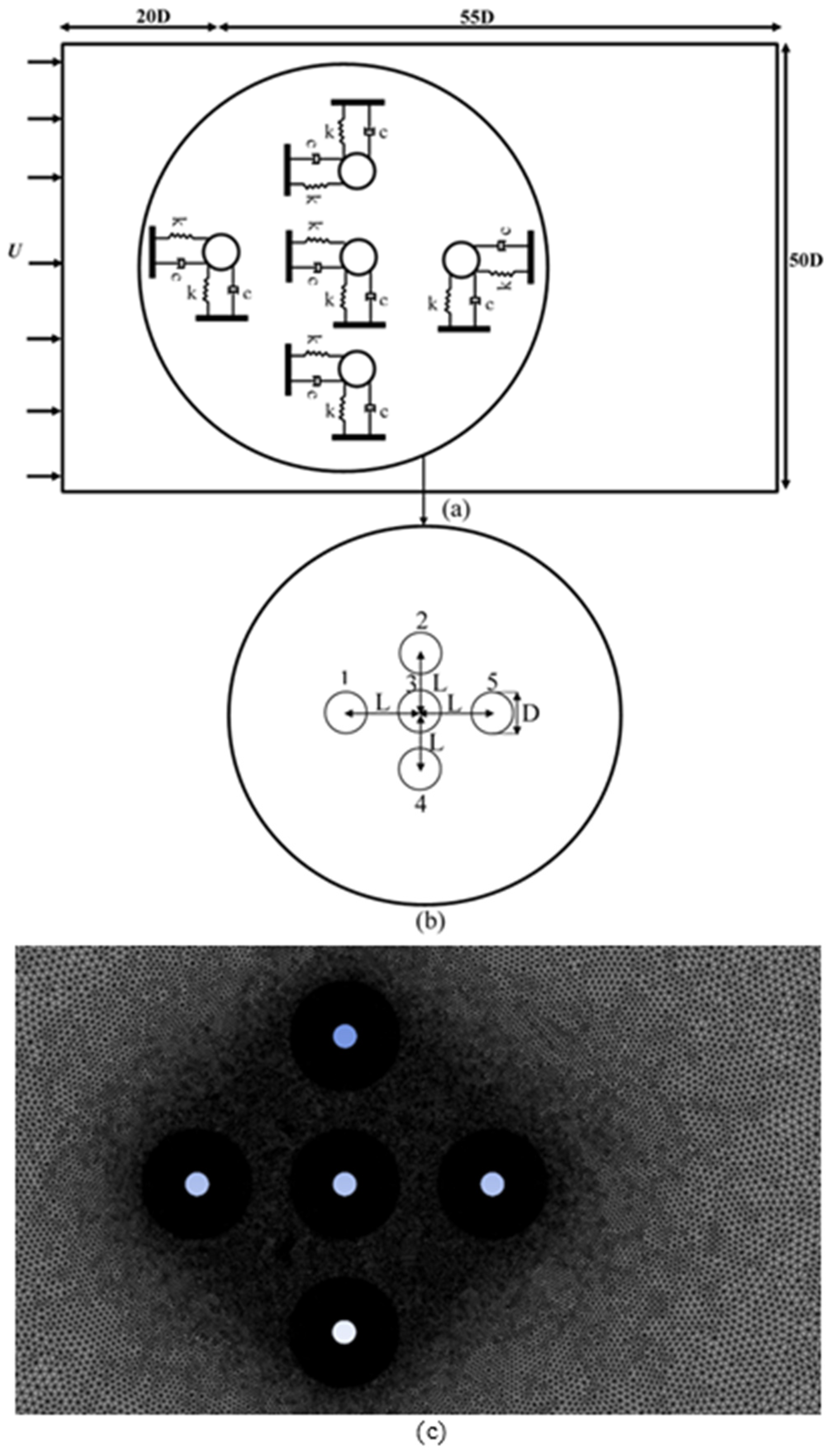
The current study focuses on the FIV behavior of five structures, each with two degrees of freedom, arranged in a cross-shaped configuration subjected to uniform flow. The Reynolds number range considered is between 100 and 600, with a fixed mass ratio of 2 for all structures. The main aim of the research is to quantify the effect of spacing ratio and reduced velocity on the VIV lock-in behavior and wake interference. The objectives of the present study include creating and validating the numerical model, obtaining and analyzing the results for the lock-in characteristics (vibration amplitudes, frequency ratios, time histories, trajectories), and vortex shedding for three spacing ratios. The background of the problem is presented in
Section 1 of this paper. The computational fluid dynamics model used for simulating the specified configuration of structures is detailed in
Section 2. Results are provided in
Section 3, and
Section 4 offers a summary of the key findings.
3. Results and Discussion
This study investigates the flow-induced vibrations of five circular cylinders arranged in a combined tandem and side-by-side configuration, referred to as a ‘cross’ arrangement, for Reynolds numbers in the range 100 < Re < 600. The results are analyzed in terms of displacement, frequency ratios, trajectory behavior, and vorticity contours at various L/D ratios.
3.1. Displacement and Frequency Ratios
Figure 3,
Figure 4,
Figure 5,
Figure 6 and
Figure 7 illustrate the maximum non-dimensional in-line (streamwise)
and cross-flow (transverse)
displacements, along with the corresponding frequency ratios for each of the five cylinders at different
L/
D ratios. Results are compared to those of a standalone (single) structure. The in-line
and transverse
vibration frequencies are obtained via Fast Fourier Transform (FFT) of the displacement signals. The non-dimensional vibration frequencies
and
represent the ratios of the in-line and transverse vibration frequencies to the natural frequency of the structure, respectively.
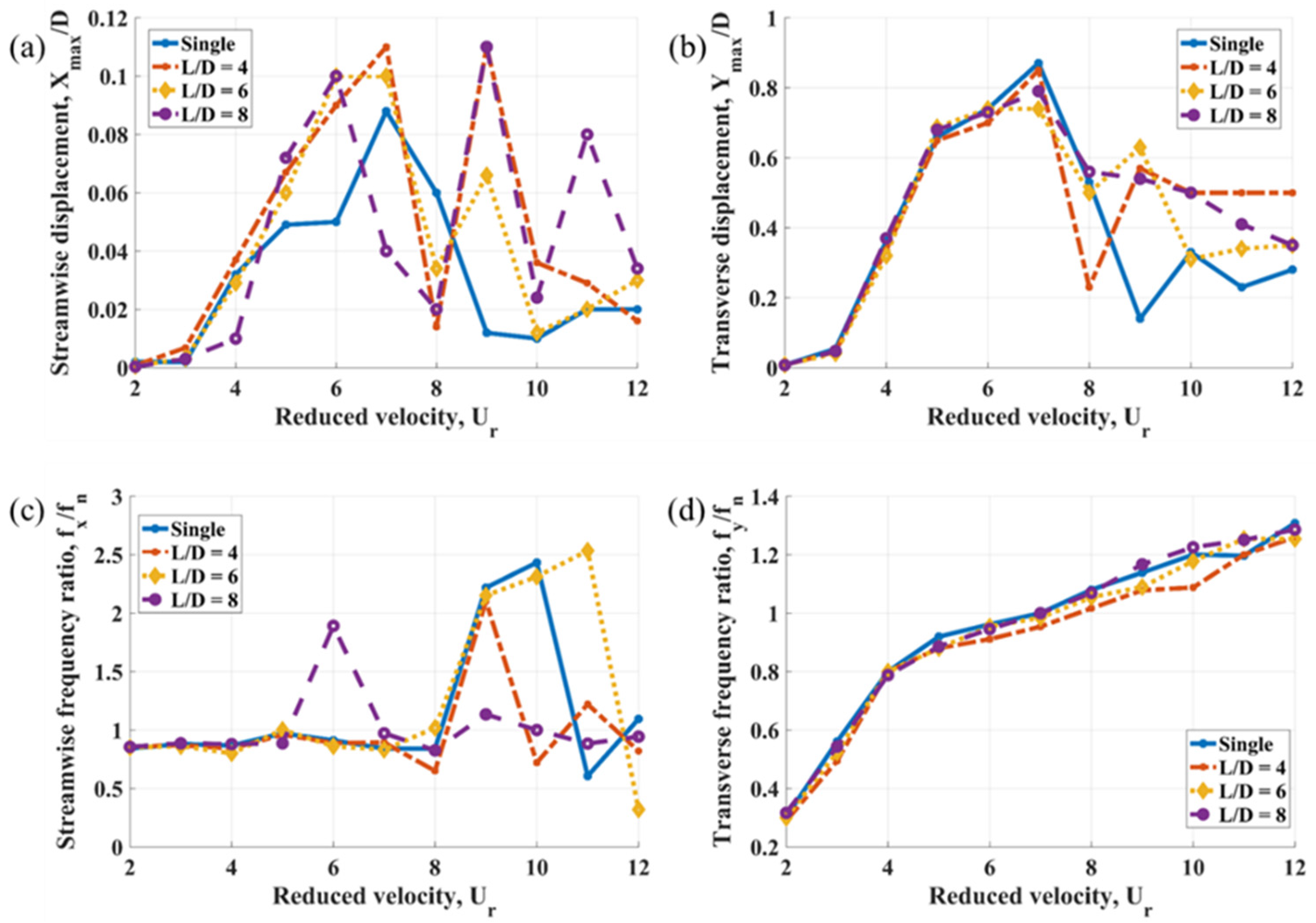
Figure 3a,b shows the lock-in peaks in both streamwise and transverse directions for Cylinder 1, where a significant increase in displacement amplitudes is observed with increasing reduced velocity [
44,
45,
46]. According to
Figure 3b, the variation in
L/
D has minimal influence on the initial branch of the transverse lock-in peak, but it does affect the super-upper branch. Specifically, the presence of downstream structures slightly reduces the maximum displacement amplitude of upstream Cylinder 1. The most pronounced impact of downstream structures on the transverse direction is observed in the lower branch of the lock-in peak, where the displacement amplitude is considerably lower for the standalone structure. This finding is consistent with the results reported in [
20].
The effects of downstream structures on the in-line lock-in peak are more complex, as illustrated in
Figure 3a. First, the presence of downstream structures leads to the appearance of additional peaks at higher reduced velocities. Second, the maximum streamwise displacement amplitude is greater for Cylinder 1 compared to that of the standalone structure. Additional in-line peak values at higher reduced velocities are accompanied by a sharp increase in the in-line frequency ratio, as shown in
Figure 3c, whereas the transverse frequency ratio in
Figure 3d exhibits a smoother trend. These patterns are relatively consistent across the cylinders in the ‘cross’ arrangement. At
L/
D ratios of 4 and 6 for Cylinder 1, the transverse vibration frequency is lower than the natural frequency in the lock-in regime, aligning with the results presented in [
20].
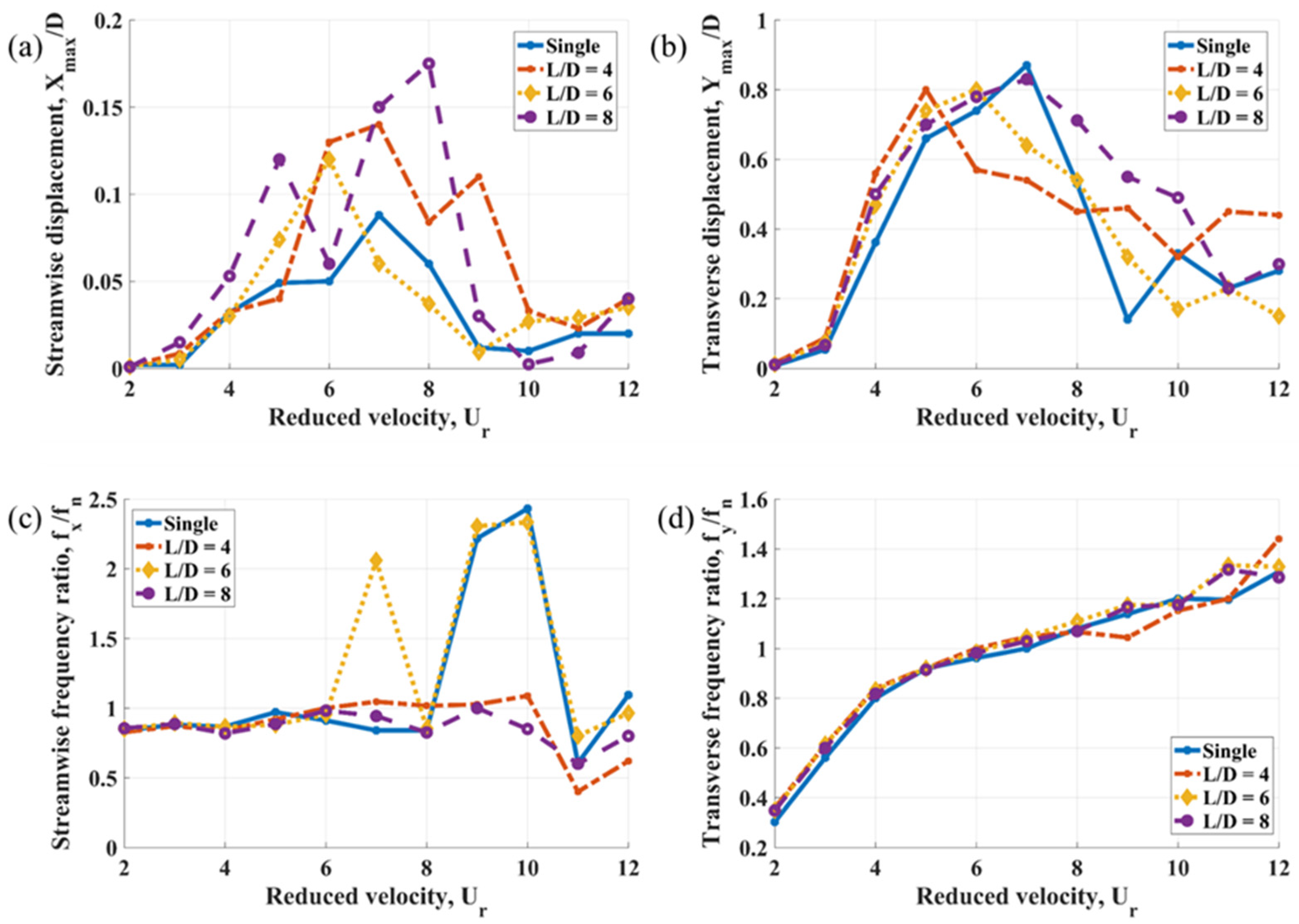
Cylinder 2 is influenced simultaneously by Cylinder 3 and staggered interactions with Cylinders 1 and 5. These interactions cause the highest maximum transverse displacement amplitude to shift to a lower reduced velocity, as illustrated in
Figure 4b. For instance, the peak occurs at a reduced velocity of 5 for
L/
D = 4 and at a reduced velocity of 7 for
L/
D = 8 and the standalone structure. Increasing the
L/
D ratio results in a noticeable widening of the transverse lock-in peak, while
L/
D = 4 yields higher transverse displacement amplitudes at reduced velocities of 11 and 12.
The effect of the spacing ratio on streamwise displacement is illustrated in
Figure 4a. Across all ‘cross’ arrangement cases, the displacement amplitude of Cylinder 2 is greater than that of the standalone structure. As the spacing ratio increases, the maximum streamwise displacement amplitude also rises, reaching approximately twice the maximum amplitude of the single structure at
L/
D = 8.
A more complex wake-induced vibration behavior at higher reduced velocities is observed for Cylinder 3 in both lock-in peaks shown in
Figure 5a,b. The maximum streamwise displacement, similar to that of Cylinder 2, is recorded at a spacing ratio of
L/
D = 8; however, the streamwise displacement amplitude of Cylinder 3 is three times the amplitude of the standalone structure. Two streamwise peaks at
L/
D = 6 illustrate the combined effects of vortex-induced and wake-induced vibrations. The highest transverse displacement amplitudes are noted at
L/
D = 6 and
L/
D = 8, occurring at reduced velocities of 9 and 10, respectively.
The transverse displacement peaks of Cylinder 4 in
Figure 6b closely mirror the trend observed for Cylinder 2, where an increase in spacing ratio results in a widening of the lock-in peak. The maximum transverse displacement amplitude, similar to that shown in
Figure 4b, is associated with the single structure, while the highest lower branch corresponds to a spacing ratio of 4. Additionally, Cylinder 4 exhibits a distinct in-line response, as shown in
Figure 6a, where the highest streamwise displacement amplitude occurs at a spacing ratio of 4 and a reduced velocity of 9.
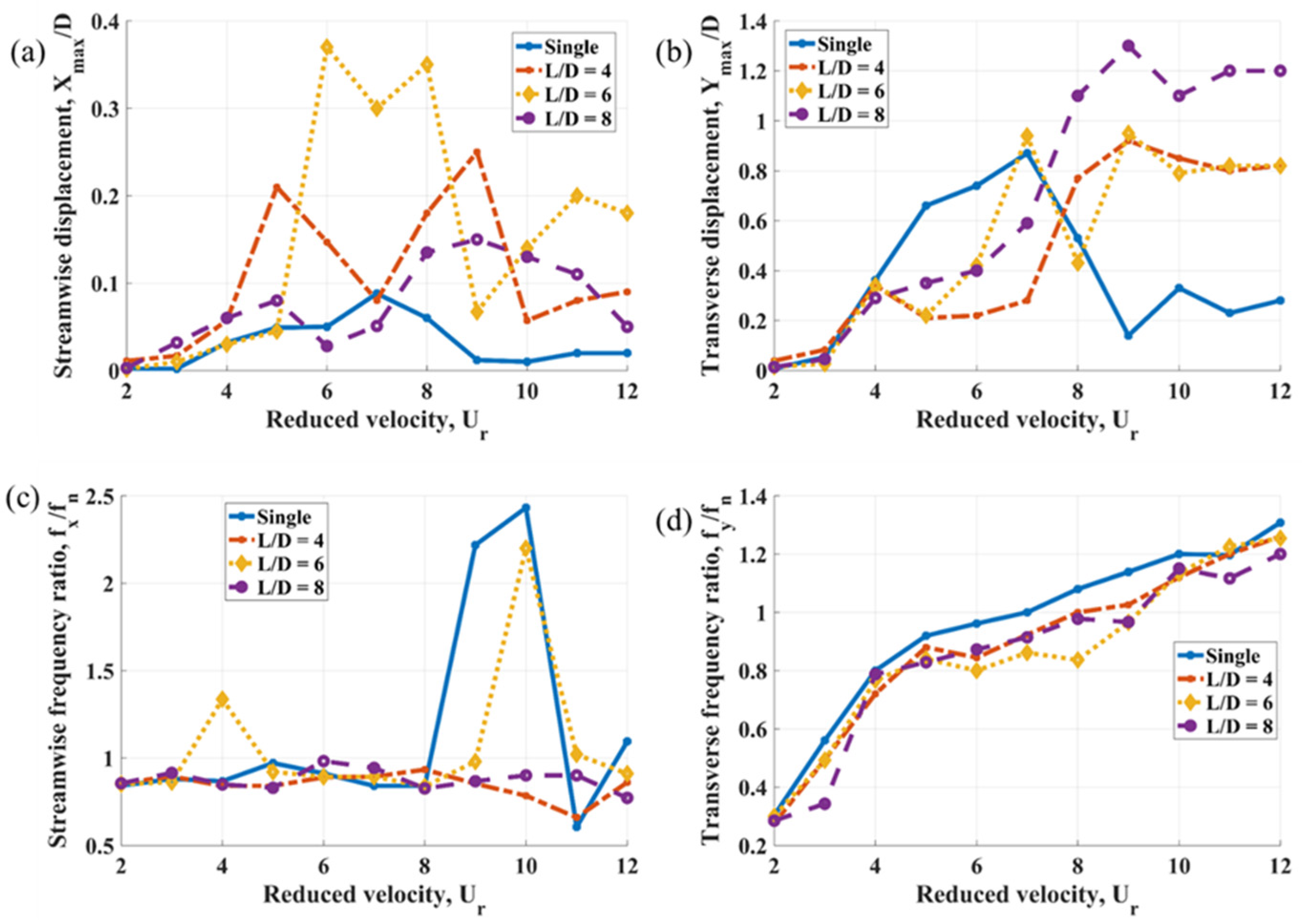
The streamwise displacement peak of Cylinder 5 does not exhibit a consistent pattern with respect to the spacing ratio, as shown in
Figure 7a. The highest and narrowest peak corresponds to a spacing ratio of 6 and is influenced by vortex-induced vibrations, based on the range of reduced velocity.
Figure 7b illustrates significant differences in the transverse displacement between the single structure and Cylinder 5, where the vortex-induced vibration response is characterized by relatively modest displacement amplitudes. Meanwhile, wake-induced vibrations at higher reduced velocities result in a substantial increase in the transverse displacement amplitude, peaking at a spacing ratio of 8.
In summary, the highest streamwise displacement amplitude is observed in
Figure 7a for Cylinder 5, with a spacing ratio of 6 and a reduced velocity of 6, reaching 0.37
D. This value is comparable only to the streamwise displacement amplitude shown in
Figure 5a for Cylinder 3, which reaches 0.3
D at
L/
D = 8 and a reduced velocity of 8. Transverse displacement amplitudes generally remain within 1
D, except for the downstream Cylinder 5, where the maximum amplitude reaches 1.3
D at a spacing ratio of 8 and a reduced velocity of 9. This enhanced response is attributed to wake-induced vibrations, as Cylinder 5 is influenced by all upstream structures. These results are consistent with the findings in references [
20,
47].
For all examined
L/
D ratios, the transverse vibration frequencies of Cylinder 3 (midstream) and Cylinder 4 in the lock-in regime are observed to be lower than the natural frequency. For Cylinders 2 and 5, lock-in occurs at reduced velocities of 6 and 8, respectively, at a spacing ratio of 4. In general, the transverse vibration frequency increases with an increase in reduced velocity. An increasing spacing ratio significantly influences the transverse vibration frequency, particularly for Cylinders 3 and 5. The transverse vibration frequency of a single cylinder, as reported in [
20], is found to be greater than the transverse vibration frequencies of the tandem cylinders, which aligns with the findings of the current study. However, for the side-by-side cylinders (Cylinders 2 and 4), the transverse vibration frequencies exceed those of the single cylinder across all considered spacing ratios in this research.
For 2 ≤ ≤ 6, the streamwise vibration frequency is not significantly affected by L/D ratios of 4 and 8 for all cylinders. However, for Cylinders 3 and 5 within this range of reduced velocity at L/D = 6, a decrease and an increase in the streamwise vibration frequency at a reduced velocity of 4 are observed, respectively. At L/D = 4, the streamwise vibration frequency remains below the natural frequency of the system for all cylinders in the lock-in regime, except for Cylinder 2, where lock-in occurs at a reduced velocity of 6. Significant changes in the streamwise vibration frequency are observed for all cylinders, particularly for the midstream and downstream cylinders at the spacing ratio of L/D = 6, due to the wake interference regime.
The transverse amplitudes of the upstream cylinder exhibit a trend similar to that of a single cylinder. Across most of the examined reduced velocities, midstream and downstream cylinders demonstrate significantly greater streamwise and transverse response amplitudes compared to the upstream cylinder and the two side-by-side cylinders. Notably, the transverse amplitudes of the downstream and midstream cylinders increase within the high reduced velocity range of 8 ≤
≤ 12 at
L/
D = 8, a phenomenon consistent with observations reported in prior studies [
48,
49] for the case of two tandem cylinders. The first feature of the WIV response is that Cylinder 3 in the wake of Cylinder 1 experiences vibration amplitudes higher than Cylinder 1. Similarly, Cylinder 5 in the wake of Cylinder 3 demonstrates displacement amplitudes higher than Cylinder 3. Another indicator of the wake-induced effects is in the higher displacement amplitudes of Cylinders 3 and 5, observed at high reduced velocities. Traditional VIV lock-in develops due to generation of its own vortices by the body and occurs around
= 5. In contrast, WIV is observed at higher reduced velocities, where the lower branch of the lock-in peak is expected with a corresponding reduction in the vibration amplitude. In the present study, for the mentioned structures, an increase in the vibration amplitude, instead of a decrease, is observed. Additional WIV-related phenomena are discussed in
Section 3.2, which covers trajectory analysis.
In the current simulations, some upper branches of the lock-in are split into several peaks, which is observed for both streamwise and transverse directions. For tandem structures Cylinder 3 and Cylinder 5, presence of several peaks in either direction can be explained by the transition from VIV to WIV, corresponding to the shift in the dominant vortex shedding: body’s own vortices during VIV-dominant response to vortices of the upstream structure during the WIV-dominant response. For the other structures, such multiple peaks of the upper branch indicate intermittent synchronization, interrupted by the vortex shedding of neighboring bodies. A particularly notable finding is the streamwise displacement response of the upstream structure Cylinder 1, which is a consequence of the vortex shedding process downstream, even at a large L/D ratio. This streamwise lock-in develops together with an overall deceleration of the flow around the group of structures. At the same time, the cross-flow displacement of Cylinder 1 remains relatively unaffected by the presence of vibrating downstream structures and demonstrates amplitudes close to a single structure.
As the spacing between the cylinders changes, various flow regimes and oscillation characteristics emerge, impacting the cylinders in different ways. For Cylinders 2 and 4, increasing the spacing ratio within the range of 5 ≤ ≤ 8 leads to an increase in the transverse vibration amplitude. However, for Cylinder 4, when the reduced velocity is at 10 ≤ ≤ 12, an increase in the spacing ratio (L/D) results in a decrease in the transverse response amplitude. The maximum transverse amplitude of 0.83D for Cylinder 2 occurs at a reduced velocity of 7 with an L/D ratio of 8, while Cylinder 4 reaches its maximum transverse amplitude of 0.78D at the same reduced velocity, but with L/D = 6.
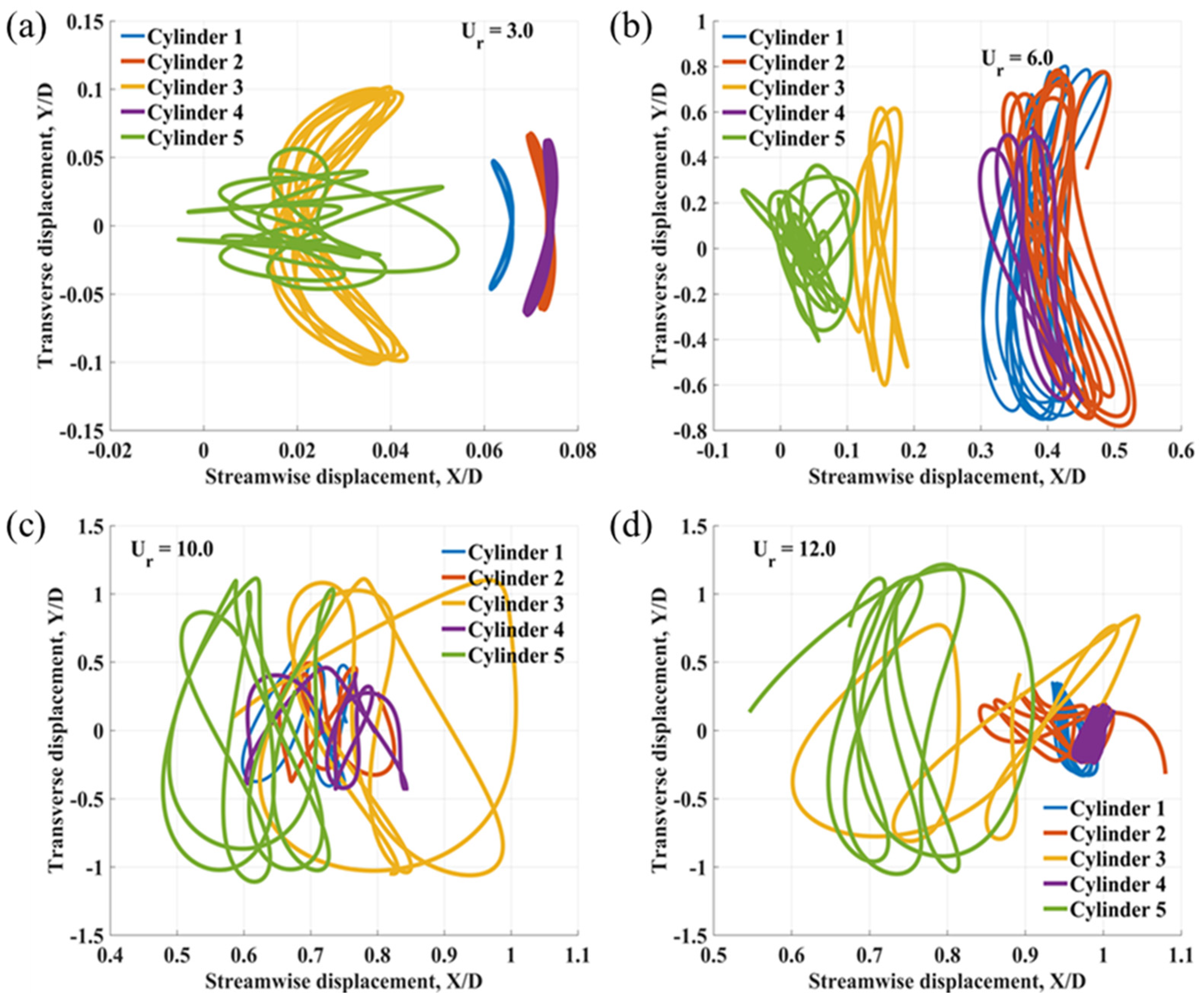
3.2. X–Y Trajectories
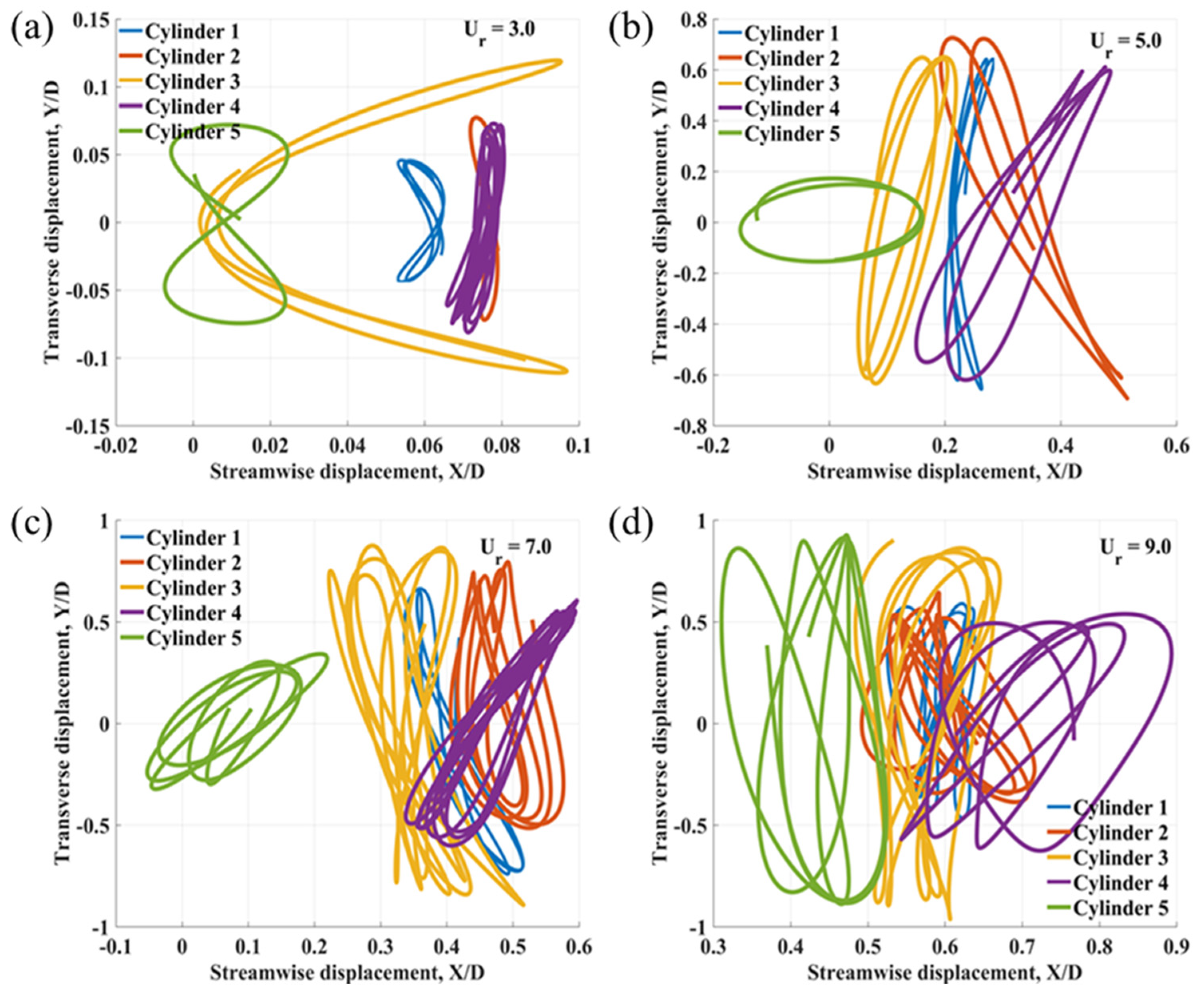
Figure 8,
Figure 9 and
Figure 10 illustrate the motion trajectories of the cylinders for
L/
D ratios of 4, 6, and 8 at various reduced velocities. At the spacing ratio of
L/
D = 4, within the range 2 ≤
≤ 4, the trajectory patterns become more distinct, with some cylinders exhibiting circular or figure-of-eight paths, characteristic of vortex-induced vibrations outside the lock-in regime. For reduced velocities in the range 5 ≤
≤ 9, the trajectories transition from figure-of-eight shapes to enclosed loops in the lock-in regime. As the reduced velocity increases from 10 to 12, the motion becomes more complex, particularly for the midstream and downstream cylinders, resulting in a beating phenomenon and the emergence of multiple vibration frequencies in both the streamwise and transverse directions.
Similar to the case of L/D = 4, at L/D = 6, and within 2 ≤ ≤ 5, the X–Y trajectories of certain cylinders exhibit moon-shaped, circular, and figure-of-eight patterns. As the reduced velocities increase from 6 to 12, the motions become increasingly complex, with some cylinders transitioning to enclosed loop shapes. The midstream and downstream cylinders display particularly intricate trajectories, characterized by irregular shapes and increased vibration amplitudes at higher reduced velocities ( = 10–12) compared to the other cylinders.
As the spacing ratio L/D increases to 8, within the range 2 ≤ ≤ 5, the motion of the downstream cylinder becomes notably complex and irregular in the trajectory shape, while the other cylinders follow figure-of-eight, moon, or C-shape trajectories. As the reduced velocity increases from 6 to 8, the downstream cylinder continues to exhibit complex and irregular motion, whereas the remaining cylinders adopt enclosed loop trajectories, consistent with the lock-in regime. For reduced velocities between 9 and 12, both the midstream and downstream cylinders demonstrate increasingly erratic and irregular trajectories, accompanied by greater vibration amplitudes.
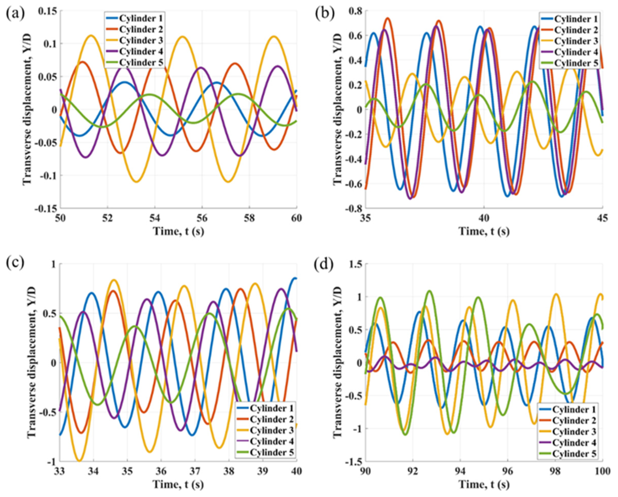
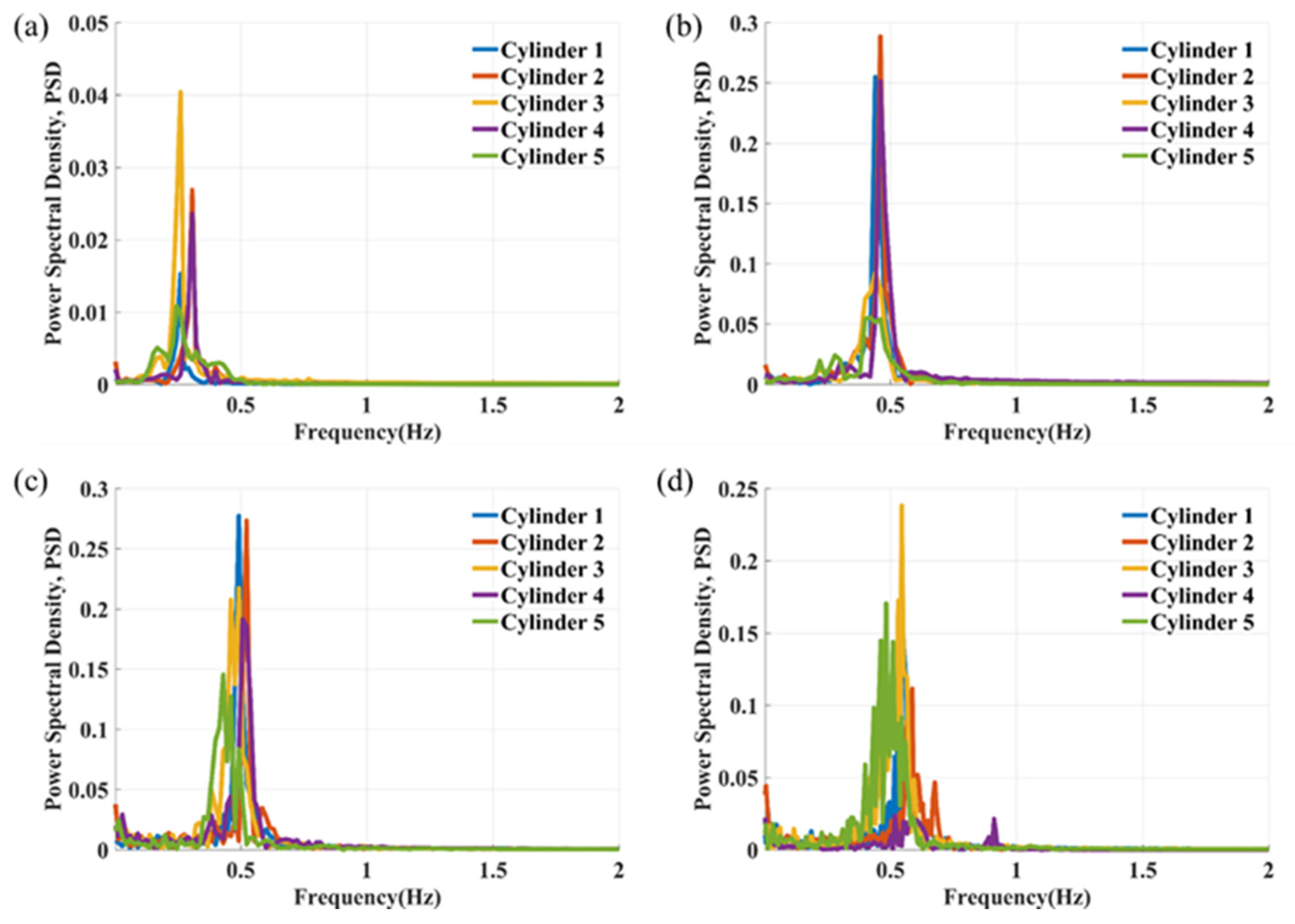
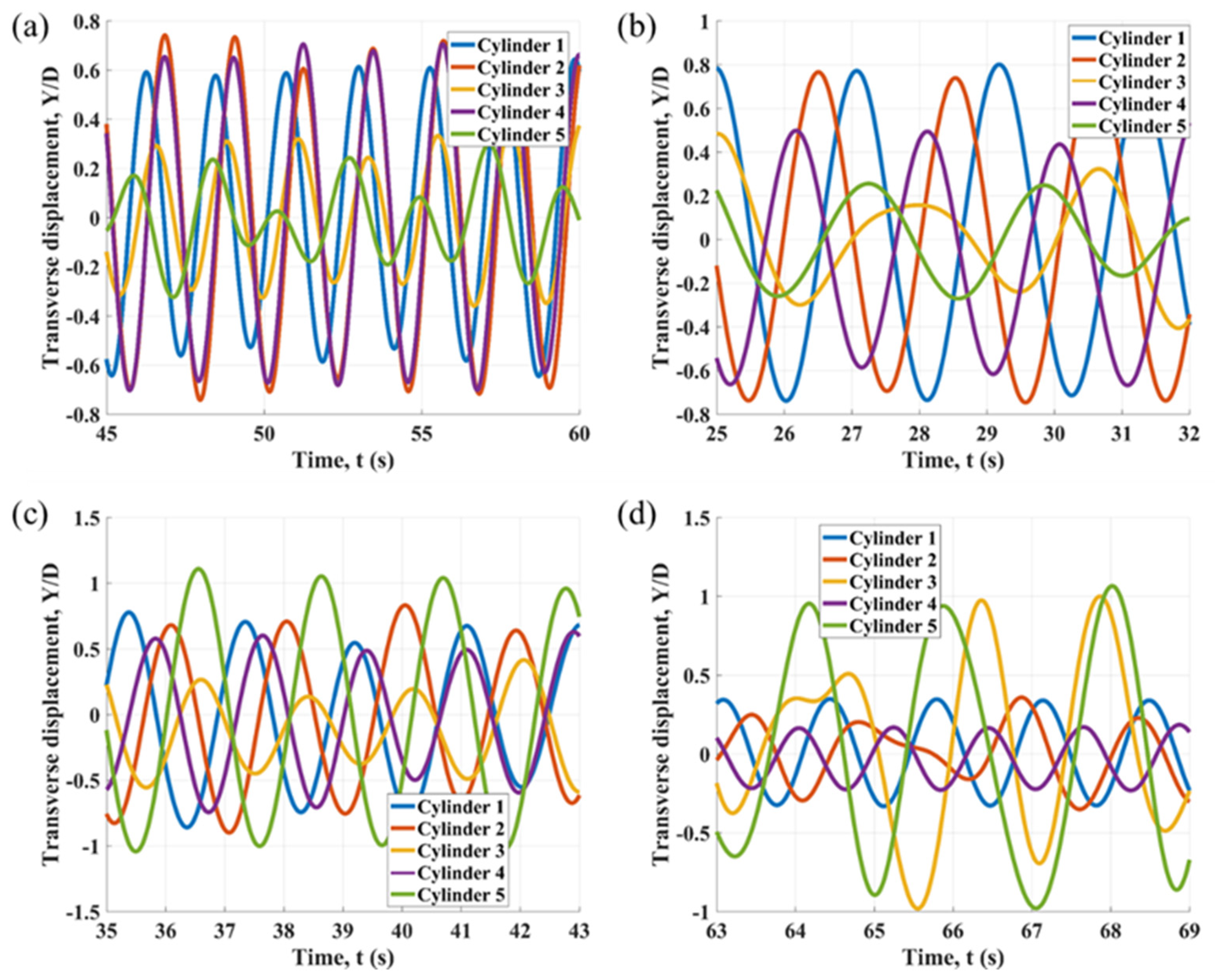
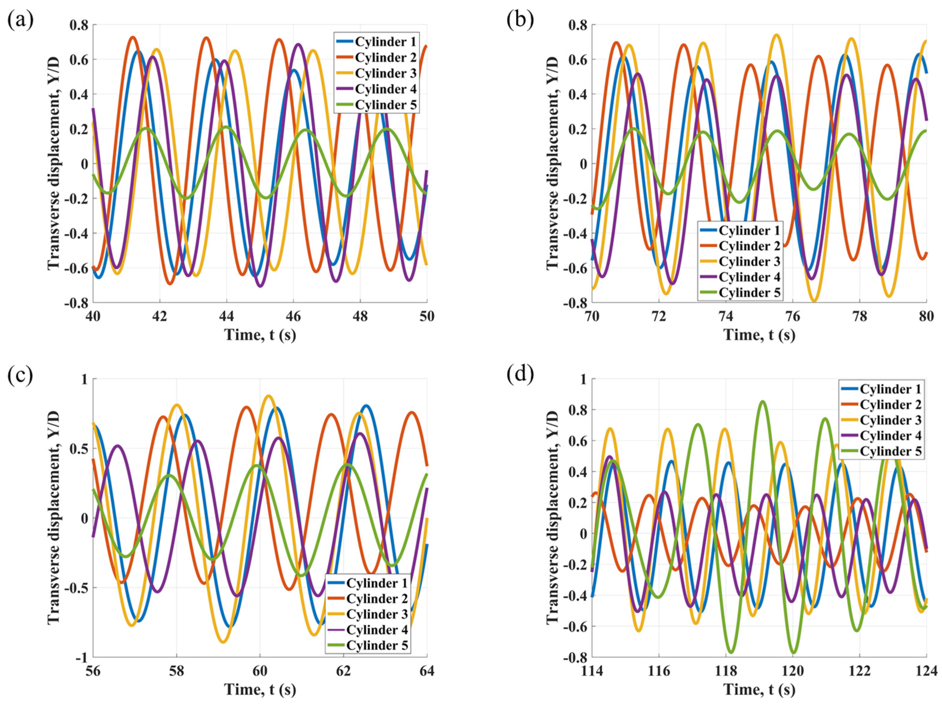
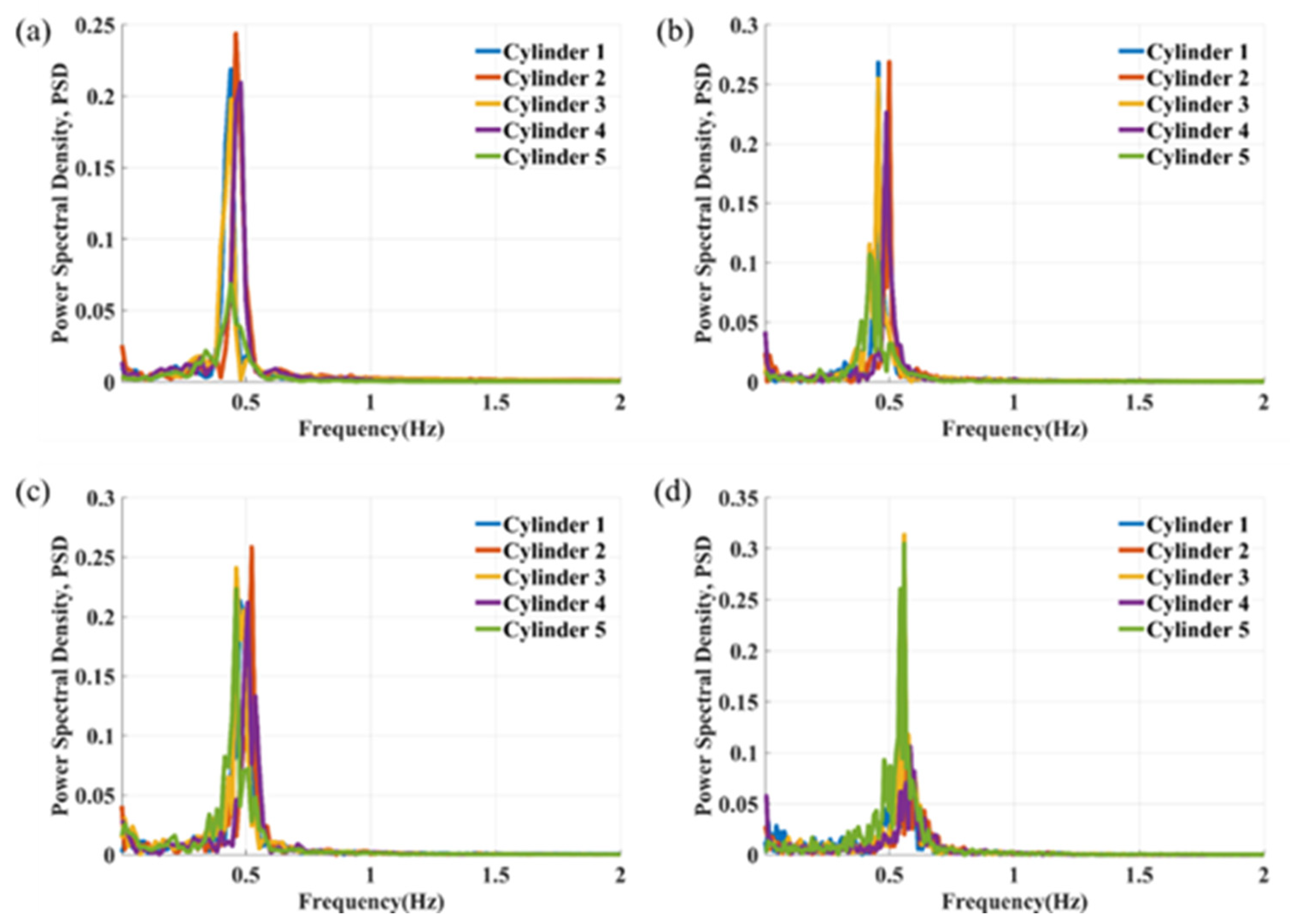
3.3. Time History and Frequency Analysis of Transverse Displacement
Figure 11 and
Figure 12 and
Appendix A illustrate the time histories and spectral characteristics of the transverse displacement of the five cylinders at various reduced velocities for the specified spacing ratios. In
Figure 12, single dominant frequency peaks are observed for Cylinders 1, 2, and 4 across all reduced velocities at
L/
D = 4. In contrast, Cylinders 3 and 5 exhibit several closely spaced frequency components, particularly at a reduced velocity of 10. For Cylinder 5, an increase in the spacing ratio leads to a greater number of competing peaks in the FFT results, as demonstrated in
Figure A2 and
Figure A4, especially at higher reduced velocities. This observation confirms the influence of wake-induced vibrations on the structural response. Concurrently, the dominant frequency of the transverse vibration of Cylinder 5 decreases. Resulting complex signals of Cylinder 5 at high reduced velocities are illustrated in
Figure A1 and
Figure A3. The effect of increasing the spacing ratio on the FFT results is notably less pronounced than effects from WIV.
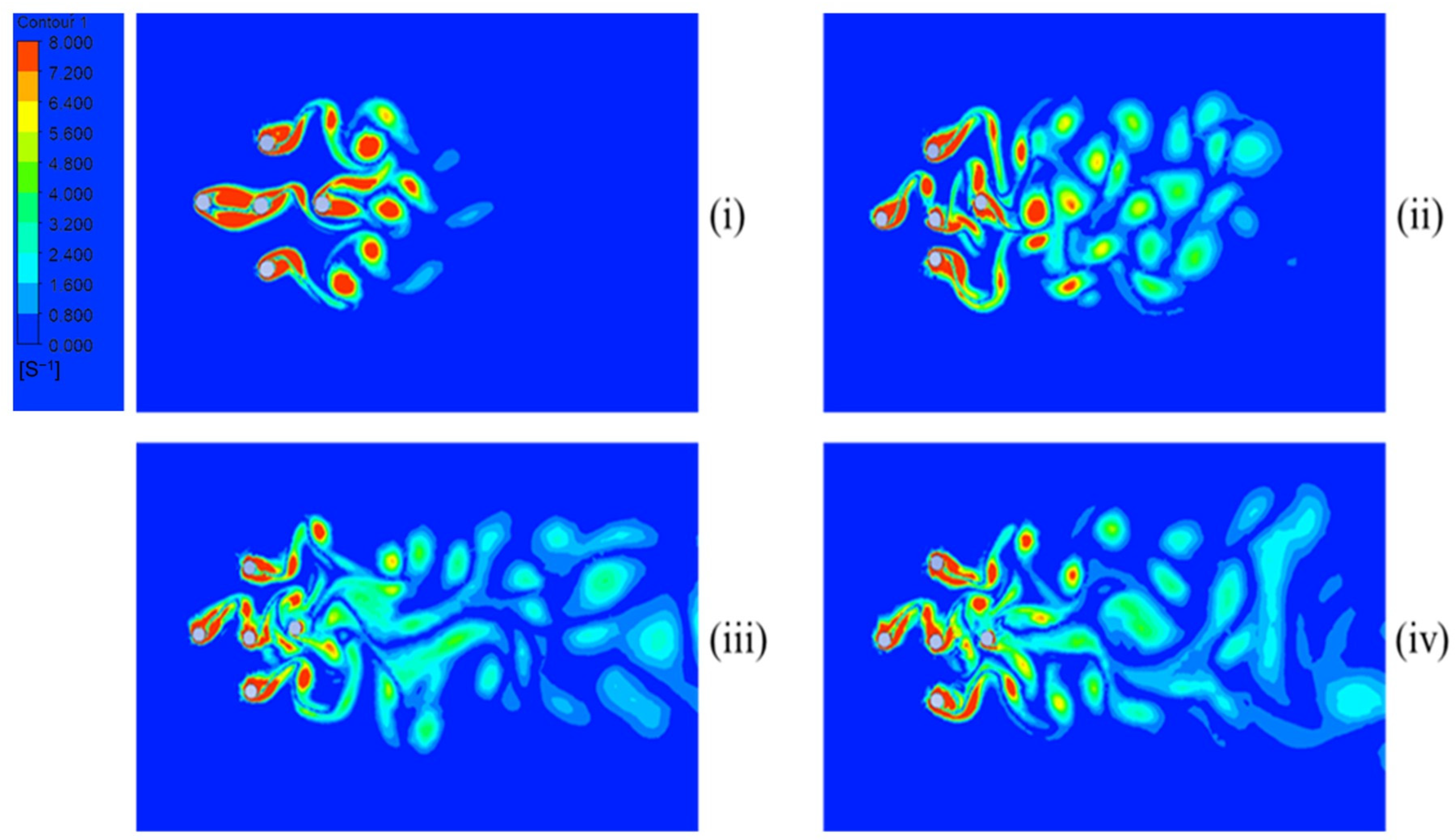
3.4. Vorticity Contours
Figure 13,
Figure 14 and
Figure 15 illustrate vorticity contours at
L/
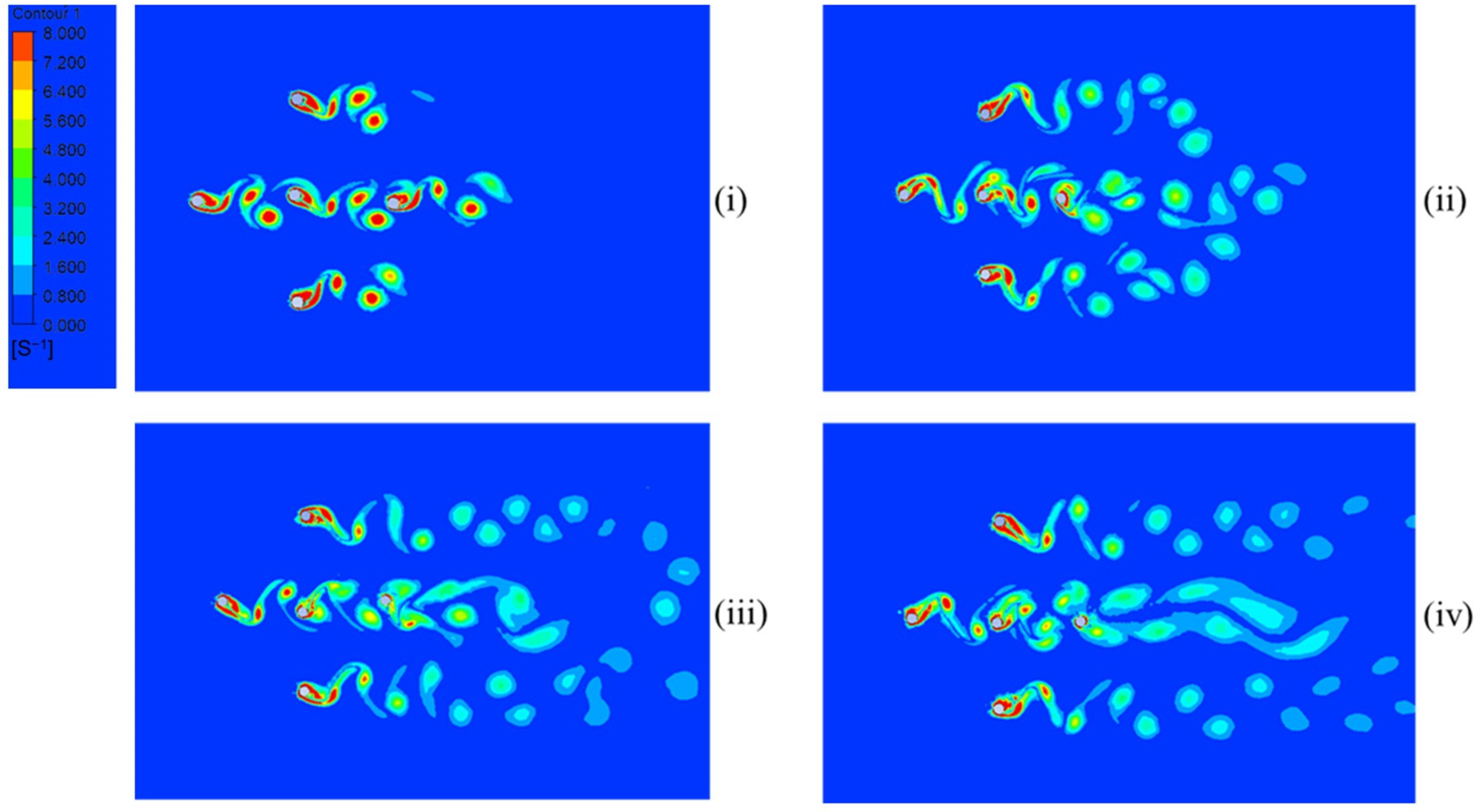
D ratios of 4, 6, and 8 at various time intervals with a reduced velocity of 7. The wake structure exhibits alternating vortex shedding patterns. At later time instances, specifically in
Figure 13iii and
Figure 14iv, vortex merging is observed for
L/
D = 4, resulting in unsteady wake interactions. The presence of multiple cylinders alters the classical von Kármán vortex street, leading to complex wake dynamics. For
L/
D = 6 and 8, at later time frames in
Figure 14iii,iv and
Figure 15iii,iv, a single pair of vortices forms downstream of the trailing cylinder. The dominant vortex shedding mode is the 2S pattern, where one vortex is shed alternately from each side of the cylinder during each oscillation cycle, producing two single vortices per period.
4. Conclusions
This study systematically investigates the flow-induced vibrations of five circular cylinders arranged in both tandem and side-by-side configurations, forming a ‘cross’-shaped layout. By varying the spacing ratio (L/D) and reduced velocity (), this research analyzes displacement, frequency ratios, motion trajectories, power spectral density, and vorticity contours to gain insights into the hydrodynamic interactions among the cylinders.
The results demonstrate that the oscillatory behavior of the cylinders is significantly influenced by the spacing ratio, relative position, and the resulting hydrodynamic wake interference effects. The transverse response amplitudes exhibit a strong dependence on the reduced velocity, characterized by the lock-in phenomenon followed by wake-induced vibrations. The midstream and downstream cylinders display the highest oscillation amplitudes, particularly at elevated reduced velocities, due to wake-induced interactions. The presence of multiple cylinders alters the classical vortex shedding process, leading to complex wake patterns and vorticity structures.
Key findings from this study include:
Influence of Spacing Ratio: Increasing L/D ratio generally amplifies the transverse vibration amplitudes of the midstream and downstream cylinders but has varying effects on the side-by-side cylinders. The wake interference regime significantly influences the vibration response, particularly at L/D = 6.
Trajectories and Oscillation Patterns: Motion trajectories transition from figure-of-eight to enclosed loop patterns within the lock-in regime. At higher reduced velocities, irregular oscillations are observed, especially for the midstream and downstream cylinders.
Power Spectral Density: A dominant vibration frequency, corresponding to the vortex shedding frequency, is observed across all cases. Secondary spectral peaks are most prominent for the downstream cylinder.
Vorticity Dynamics: The wake structures exhibit alternating vortex shedding patterns, with increased vortex merging at lower spacing ratios (L/D = 4). At larger spacing ratios, single vortex pairs form downstream, with the dominant shedding mode identified as 2S.
This study provides a comprehensive analysis of the flow-induced vibration behavior of multiple elastically mounted cylinders, arranged in a complex configuration. The findings offer insights into fundamental wake interference mechanisms and the resulting vibration responses in five-body systems subjected to fluid flow. These insights are particularly relevant to the design and operation of offshore platforms, where marine risers and umbilicals are exposed to fluid–structure interaction phenomena. In such systems, understanding and accurately predicting vibration characteristics are critical for ensuring structural integrity, operational efficiency, and the extended lifespan of structures. The outcomes of this investigation could serve as a reference for future numerical and experimental studies.
Future research could expand upon this work by considering three-dimensional effects and exploring alternative cross-sectional geometries to better understand geometry-induced variations in vibration behavior. Additionally, investigating the layout of five-body systems in different external flow regimes is of interest for evaluating real-world scenarios.


